Thermal Assessment of Selective Solar Troughs


1
ME Department, KFUPM Box 1913, Dhahran 31261, Saudi Arabia
2
K.A.CARE Energy Research & Innovation Center, Dhahran 31261, Saudi Arabia
*
Author to whom correspondence should be addressed.
Energies 2019, 12(16), 3130; https://doi.org/10.3390/en12163130
Submission received: 15 July 2019
/
Revised: 2 August 2019
/
Accepted: 12 August 2019
/
Published: 15 August 2019
Abstract
:A comparative study was carried out incorporating a novel approach for thermal performance evaluations of commonly used parabolic trough collectors, namely the Euro, Sky, and Helio troughs. In the analysis, pressurized water and therminol-VP1 (eutectic mixture of diphenyl oxide (DPO) and biphenyl) fluid were introduced as working fluids, and the governing equation of energy was simulated for various working fluid mass flow rates and inlet temperatures. The thermal performance of the troughs was assessed by incorporating the first- and second-law efficiencies and by using temperature increases and pressure drops of the working fluid. It was found that the first-law efficiency of the troughs increased with the working fluid mass flow rate, while it decreased with an increasing working fluid inlet temperature. The first-law efficiency remained the highest for the Euro trough, followed by the Sky and Helio troughs. The second-law efficiency reduced with an increasing working fluid mass flow rate, while it increased with an increasing working fluid inlet temperature. The second-law efficiency became the highest for the Helio Trough, followed by the Sky and Euro troughs. The temperature increase remained the highest along the length of the receiver for the Helio Trough compared to that corresponding to the Euro and Sky troughs for the same mass flow rate of the working fluid. The pressure drops in the working fluid became high for the Euro Trough, followed by the Sky and Helio troughs. The pressurized water resulted in higher second-law efficiency than the therminol-VP1 fluid did for all of the troughs considered.

1. Introduction
The utilization of renewable energy resources has become a necessity rather than a preference due to the recent changes in the climate. The most abundant renewable energy source is solar energy, which enables us to obtain the concentrated thermal radiation power on surfaces. Various design configurations have been introduced to harvest solar thermal energy for various thermal applications. The parabolic trough is one of the main solar energy concentrators for harvesting solar thermal power. In general, three design configurations of troughs are well known for practical applications. These include the Euro Trough [1], Sky Trough [2], and Helio Trough [3]. On the other hand, many factors affect the performance of solar troughs, some of which include the concentration of solar radiation, wind speed, working fluid type, mass flow rate, and inlet temperature of the working fluid. The thermal performance of troughs and receivers in terms of first- and second-law efficiencies can be improved via the proper selection of operating conditions such as working fluid type, mass flow rate, and the inlet temperature of the working fluid. Although the design configurations of solar troughs and receivers are well established, the proper selection of a solar trough system to maximize its thermal performance has become critical for certain practical applications. The working fluid, such as pressurized water or therminol liquid, at different mass flow rates influences the trough system performance. Hence, thermal analysis of a trough system’s performance in terms of first and second law analysis has become essential to assessing the influence of the working fluid type and its mass flow rate on the system performance.
Considerable studies have been carried out formulating the thermal performance of solar trough systems. A model study of thermal flow systems and the characteristics of carrier fluid remains the center of attention in the assessment of solar collector systems’ performances [4]. A falling-particle solar receiver with a closed cavity arrangement provided improved collector efficiency due to heat recovery from the particles and the minimization of reradiation losses [5,6]. Introducing a gradually varying volumetric solar receiver could also reduce radiation losses from the surface and improve the absorption of solar radiation while enhancing the receiver performance [6]. In some applications, porous structures have been integrated into the solar absorbing media to improve thermal energy exchange with the working fluid [7,8,9]. Incorporating low porous structures improved the working fluid temperature at the solar receiver outlet [8]. In addition, metallic foams have become one of the porous structures used as an absorbing media in the solar harvesting device [10]. However, heat losses from the solar harvesting device play a major role in reducing the device performance. In general, the heat loss from the surface is presented as a percentage of the solar energy harvested, and for certain designs of the solar receiver, a linear correlation is present between the heat loss and the harvested solar energy [11]. The minimization of heat losses became critical when the solar receiver was integrated with an engine such as a sterling engine [12]. The optimal design of a solar trough resulting in improved energy harvesting while minimizing heat losses was necessary for efficient operation of the energy harvesting system [13]. The gradual variation of the receiver volume could reduce the heat loss and improve solar absorption [13]. The geometric configuration in terms of the depth of the device also influenced the heat losses from the solar receiver while lowering device performance in shallow depths [14]. Moreover, thermal absorber tubes remained popular for concentrated solar absorption in thermal power systems [15]. The displacement of the tube in the trough system also influenced the performance of the system, which was more pronounced if the working fluid had a low inlet temperature; however, at high-temperature applications, small misalignments did not significantly lower the device performance [16]. Nevertheless, for high-temperature solar heating applications, the solar collector design should be based on three-dimensional simulations, and the resulting design configuration should be tested for further improvement of the device performance [17]. The use of nanofluids in solar collectors was shown to improve the device performance because of heat transfer enhancement [18]; however, care must be taken for the working fluid’s stability at high temperatures. In the case of experimental investigations, several studies were carried out to examine the solar receiver performance [19,20]. Granular flow via a perforated solar receiver was one of the preferences for the efficient operation of solar thermal systems [19], and tubular pressurized flow systems have also attracted attention for solar thermal applications of gas flow systems [20].
Thermal analyses of solar receivers incorporating parabolic troughs have been studied previously [4], where the main focus was an investigation of the thermal performance of the solar absorbing system in introducing new design configurations of parabolic troughs. However, evaluating the performances of various commonly used troughs in practice was left for future studies. In addition, the influence of the mass flow rate and inlet temperature of various commonly used working fluids on the thermal performance of these devices needed to be presented comparatively. Consequently, in the present study, a performance analysis of the Euro Trough, Helio Trough, and Sky Trough was carried out, and the influence of the mass flow rate and inlet temperature of the working fluid on the first- and second-law efficiencies of the thermal system was assessed. The first- and second-law efficiencies of these troughs were compared after incorporating pressurized water and therminol as the working fluid. The efficiency prediction was validated with that reported in a previous study [21].
2. Materials and Methods
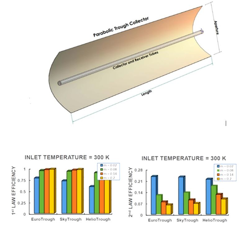
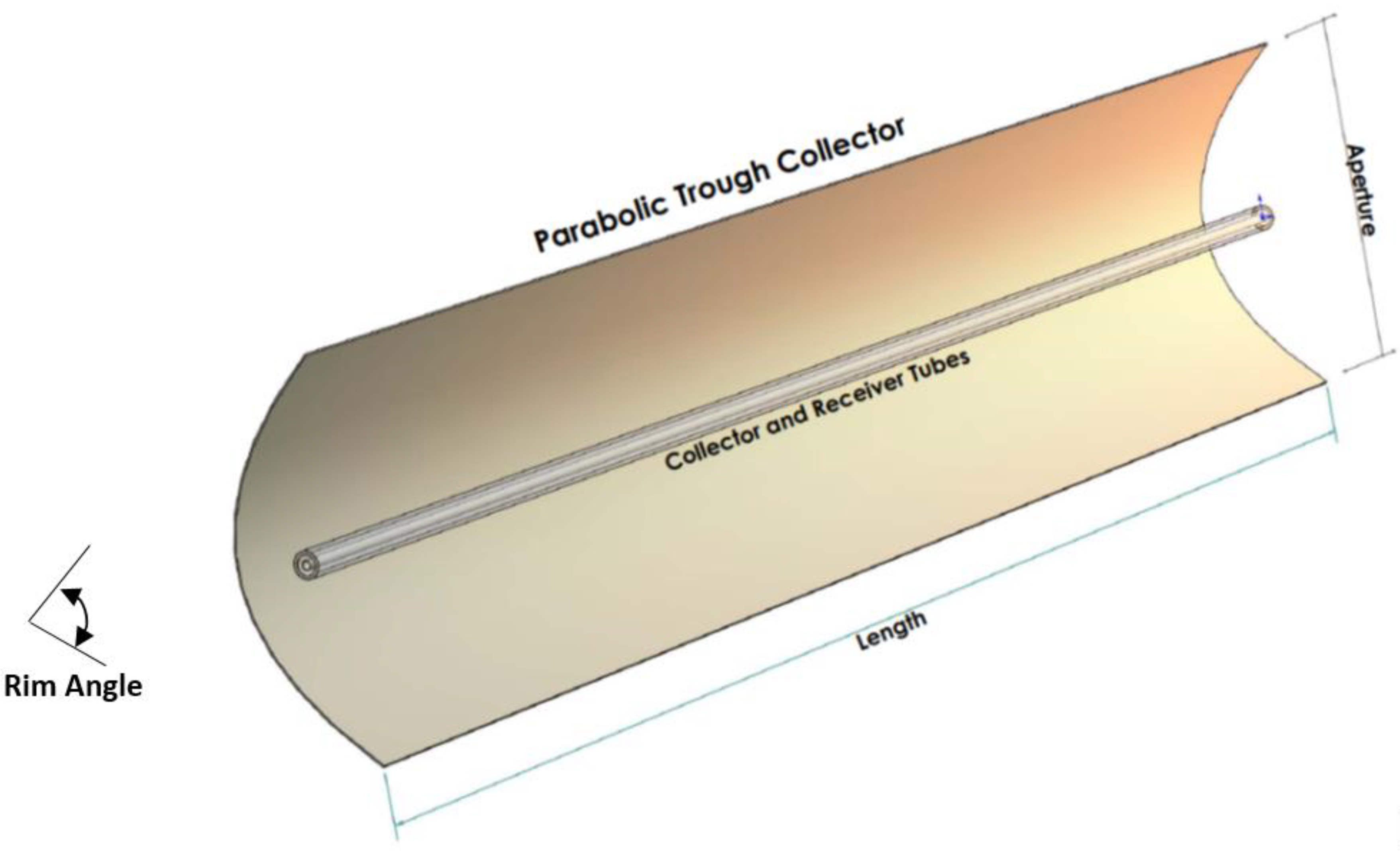
Figure 1 shows a schematic view of a solar parabolic trough collector (PTC), while Table 1 provides PTC data. The first- and second-law efficiencies of the most commonly used troughs, namely the Euro, Sky, and Helio troughs, were formulated.
In a previous study [22], the trough was formulated through lumped analysis with only an inlet and exit. However, in the present study, the total length of each parabolic trough assembly was divided into elements (n = 120) such that the total aperture area was Aa (=). It was considered that the trough receives direct solar irradiation (Gb) while reaching its aperture area (Aa). The total solar irradiation received (Qs), which is available on the collector, is determined from [23]
where .
The solar radiation received is partly transferred to the working fluid while causing temperature increase. The energy transferred to the working fluid is considered to be the useful energy (Qu), which can be formulated after incorporating the energy balance on each fluid element, which yields [24]
where is the working fluid mass flow rate, Cp is the specific heat of the working fluid, Tfout is the working fluid outlet temperature, and Tfin is the working fluid inlet temperature. One of the most important thermal performance indicators for the solar collector is its thermal efficiency (ηth), which can be defined through the ratio of the useful energy (Qu) to the available solar irradiation (Qs). This can be written as
The useful absorbed energy for each element can be determined by incorporating heat transfer inside the absorber tube. Hence, the equation describing the heat convection heat transfer from the hot absorber to the flowing working fluid yields
where , and h is the heat transfer coefficient, which can be determined from the Nusselt number for flow inside tubes, defined as
where Dn is the receiver tube inner diameter, and k is the thermal conductivity of the working fluid. Since the Reynolds number is greater than 2000, the turbulence flow is considered in the analysis. For turbulent pipe flow, the Dittus-Boelter equation [25] can be used to evaluate the Nusselt number, which is
where Re is the Reynolds number, and Pr is the Prandtl number, defined as and .
Thermal losses (Qloss) from the trough are an important part of the energy calculations. In this case, the energy balance across the trough yields [26]
where (ηopt) is the optical efficiency of the collector. The thermal losses can be evaluated by considering the heat transfer in the solar receiver. Hence, it becomes essential to balance the energy exchange between the receiver (absorber) tube, its cover, and the surrounding environment. In a steady-state situation, the thermal energy transfer to the surroundings through the cover is associated with the thermal losses. Hence, after incorporating the thermal radiation losses while neglecting the convection losses, the following equation describes the thermal energy exchange between the absorber and its cover [22]:
where A is the area, , , σ is the Stefan–Boltzmann constant (5.67 × 10⁻⁸ W/m2 K4), ε is the emittance, and T is the temperature.
The absorber cover can exchange thermal energy with its ambient via convection and radiation heat transfer. The thermal energy loss from the absorber cover is formulated using the above equation (Qloss). Here, it is essential to indicate that for the evacuated tubes, the cover temperature is relatively low, and it takes values closer to the ambient temperature than the absorber temperature. Hence, the thermal energy loss from the cover to its ambient yields
where A is the area, , h is the heat transfer coefficient, and T is the temperature.
The exergetic performance of the collector can be evaluated by assessing the irreversibility associated with the thermal system. In this case, exergy analysis provides information about the maximum possible energy that can be harvested from the system. In general, the exergetic output is equal to the subtraction of thermal irreversibility (in terms of entropy generation) from the useful output: that is, it takes the form
where Qu is the useful output, is the entropy generation rate, and T is the temperature. The above equation can be modified to take the form [27]
where Cp is the specific heat, and ΔP is the pressure drop.
The above equation gives the exergetic output of the solar collector, which is equal to the thermal output minus the losses due to temperature and pressure drops in the receiver system. The first term in the losses part of Equation (11) is related to the heat transfer representing the heat losses of the surrounding environment. The second term is associated with the pressure losses along the tube.
Exergy analysis related to solar thermal energy was introduced by Petela [28]. The sun can be considered to be the source for thermal radiation, and hence, the exergy of emitted solar radiation is involved in a complicated formulation. However, the exergy of solar radiation can be simplified by assuming a constant surface temperature of the sun at 5770 K. The exergy of solar radiation was formulated by Petela [28], and the resulting equation yields
The exergetic performance of the solar collector can be defined through second-law efficiency (ηex), which is the ratio of exergetic output over the solar exergy input given by
where Eu is the exergetic output and Es is the solar exergy input.
The pressure drop in the tubing system can be formulated with the consideration of the friction factor (fr). In this case, the pressure drop can be formulated as
where Dri is the tube diameter, L is the tube length, ρ is the working fluid density, and u is the flow mean velocity inside the tube. The friction factor can be written from the Petukhov relation [25]:
The mean velocity of the flow can be determined from the mass flow rate inside the tube, yielding
where is the mass flow rate.
An energy equation solver (EES) code incorporating the above formulation was developed to determine the thermal efficiency (the first-law efficiency), exergetic efficiency (the second-law efficiency), temperature increase along the receiver tube, and pressure drop in the working fluid. In the simulations, the most commonly used Euro [1], Sky [2], and Helio [3] troughs were considered. A comparative study of the thermal performance of each trough is presented incorporating various working fluid mass flow rates and inlet temperatures while considering pressurized water and therminol as the heat transfer fluid.
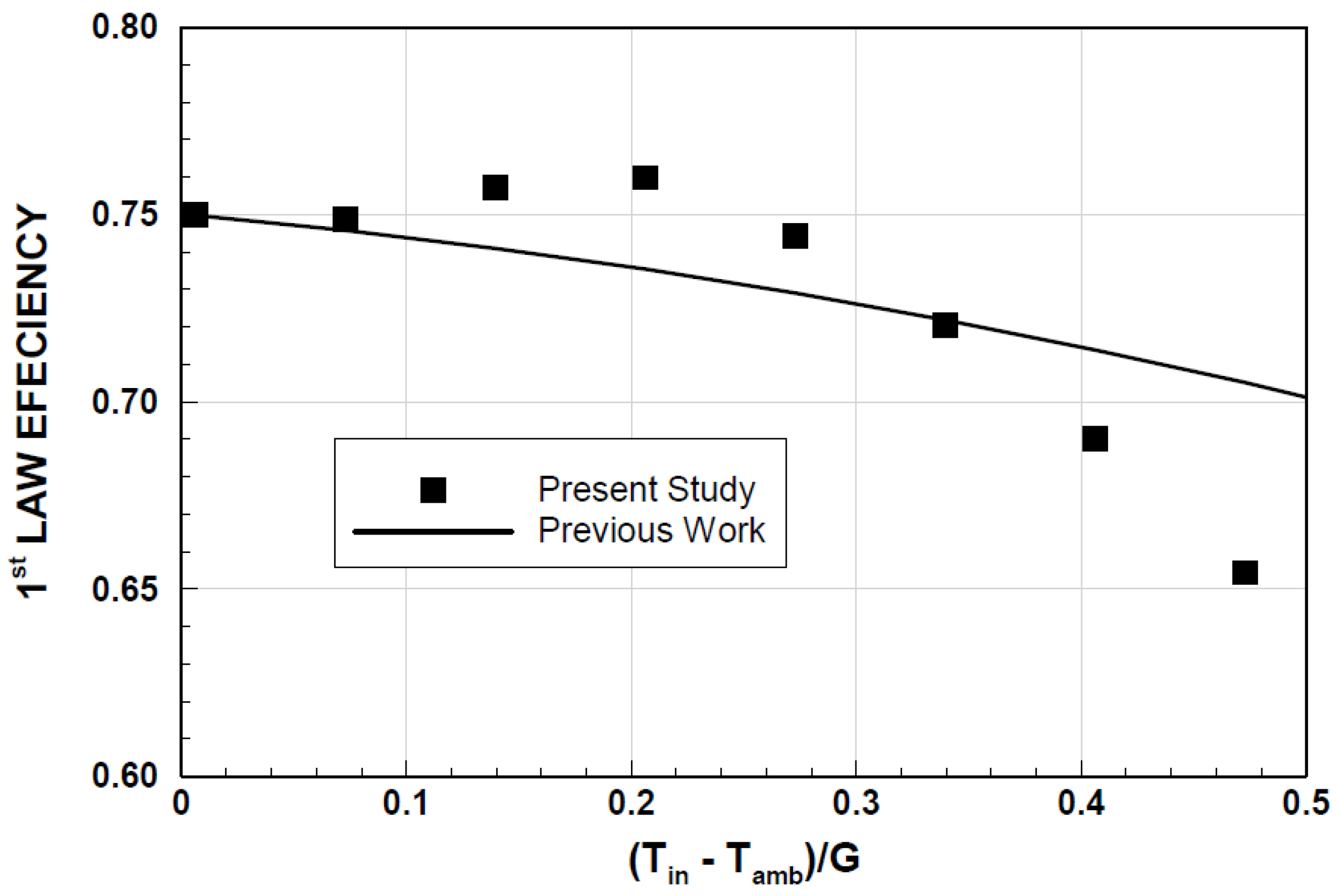
The first-law efficiency predicted by the present formulation was validated through data presented in an earlier study [21] while keeping the same working conditions. Figure 2 shows a comparison between current predictions and the previous study [21] of the first-law efficiency with a normalized temperature difference ((Tin−Tamb)/G, where Tin is the receiver inlet temperature, Tamb is the receiver ambient temperature, and G is the solar irradiation). The findings revealed that both results were in good agreement, and the differences between both results were within an acceptable range. The maximum difference between the experimental data and the predictions was on the order of 8%, which occurred at low solar radiation. The small differences were because of the experimental error, which was on the order of 8%, and the round-off errors in the simulations.
3. Results and Discussion
A thermal analysis of a concentrated solar thermal system was carried out incorporating the parabolic troughs, namely the Euro Trough, Sky Trough, and Helio Trough. The first- and second-law efficiencies were formulated by adopting the configurations of the troughs, and a comparative study was introduced to assess the thermal performance of each trough for various mass flow rates and inlet temperatures of the working fluids.
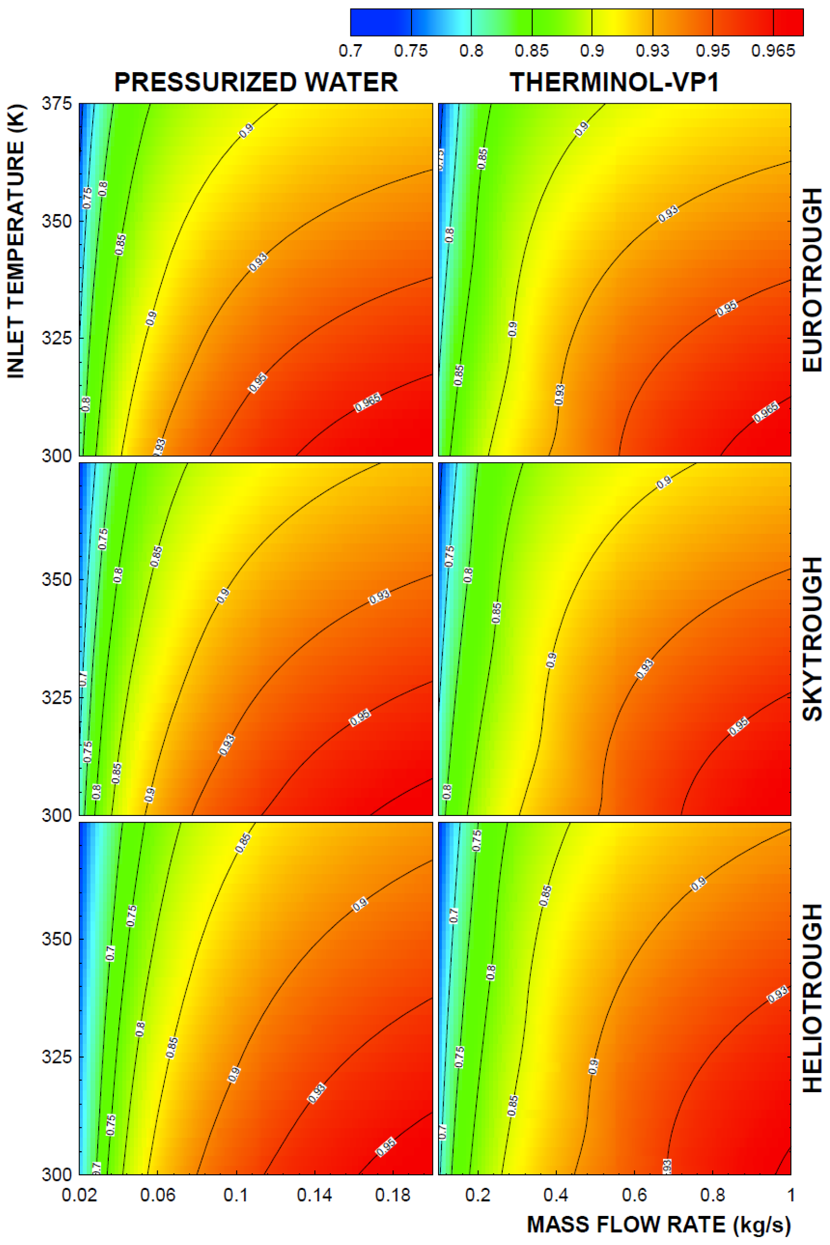
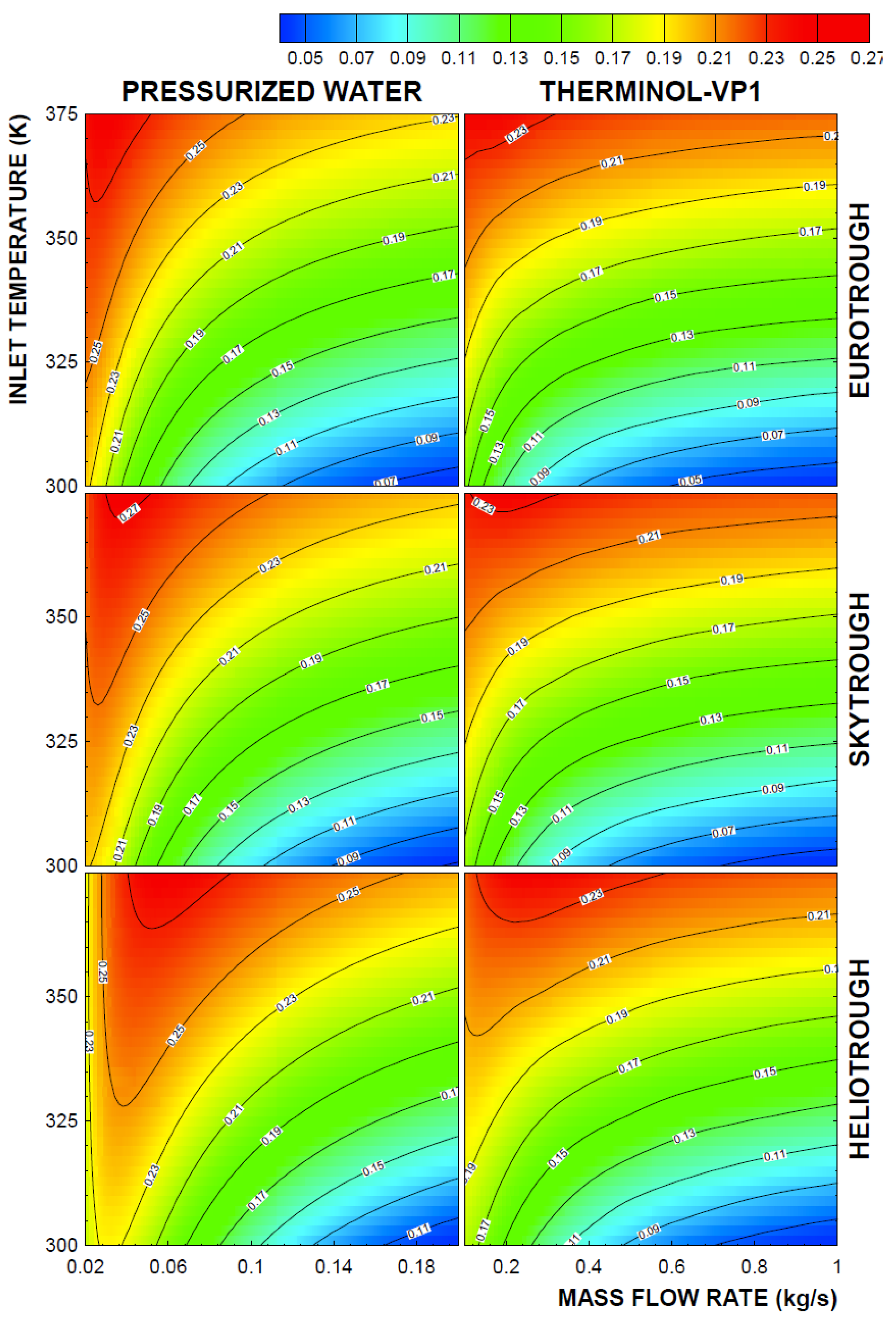
Figure 3 shows the first-law efficiency contours with working fluid inlet temperature and mass flow rate for two different working fluids, namely pressurized water and therminol-VP1. The inlet temperature resembled the conditions when the solar trough was used in the series. In this case, the inlet temperature for the first trough could be 300 K, and the following trough in the series connection was 375 K. In addition, in order to keep similar first-law efficiency behavior at a similar working fluid inlet temperature, the range of the mass flow rate of the working fluid was changed for therminol-VP1. However, the equations used for determining the first-law efficiency were the same for both fluids while incorporating the appropriate thermal properties. In general, an increasing mass flow rate enhances the first-law efficiency of the system, where an increasing mass flow rate in the system improves the energy absorbed from the solar radiation by the working fluid. This was true for the Euro, Sky, and Helio troughs. The range of the inlet temperature of the pressurized water (as the working fluid), sustaining high efficiency, attained higher values than those corresponding to therminol-VP1, i.e., the maximum temperature of the pressurized water sustaining the first-law efficiency within the range of 0.95 was 312 K, while it was almost 305 K for therminol-VP1 in the Helio trough. This situation changed with a change in the trough type. In this case, the Euro and Sky troughs attained similar range of inlet temperatures for an efficiency of 0.95 using the pressurized and therminol-VP1working fluids. After incorporating the same mass flow rate and inlet temperature ranges, the performances of the troughs in terms of the first-law efficiency became higher for the Euro trough, followed by the Sky and Helio troughs. This finding remained the same for both the pressurized and therminol-VP1 working fluids. However, the therminol-VP1 working fluid resulted in slightly higher first-law efficiency than pressurized water did for a given mass flow rate. In addition, an increasing mass flow rate reduced the maximum inlet temperature of the fluid for high values of the first-law efficiency. Consequently, for a fixed high value of mass flow rates and inlet temperatures of the working fluid, the Euro trough resulted in higher first-law efficiency than the Sky and Helio troughs did. On the other hand, in order to obtain large values of the first-law efficiency, the mass flow rate of the working fluid should remain high, while the range of the inlet temperature of the working fluid should remain low. This finding demonstrates that for a series of troughs, the second trough would result in lower first-law efficiency than the first trough in the series would. This finding was true for all of the types of troughs incorporated in the present study.
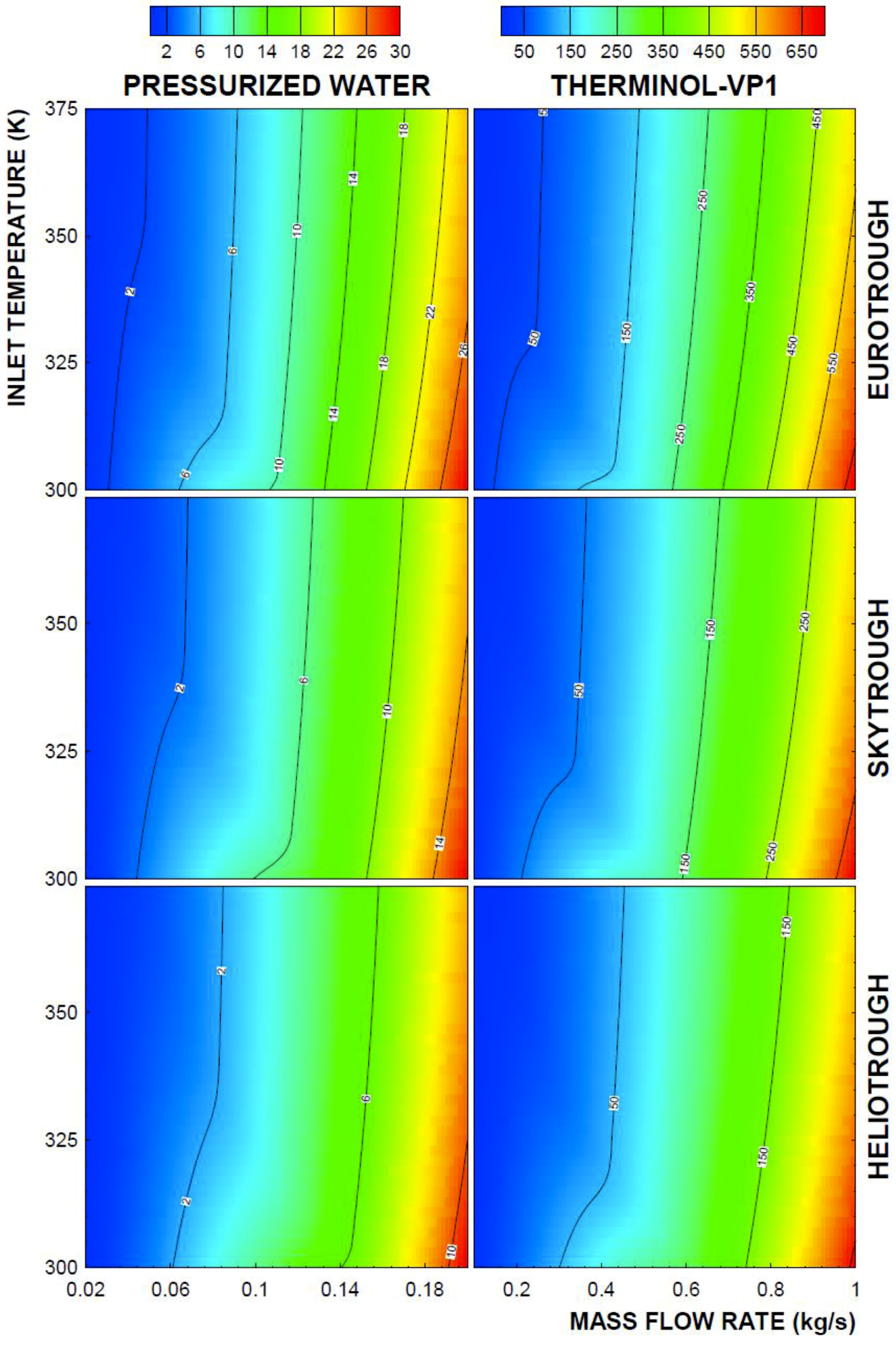
Figure 4 shows the contours of the second-law efficiency of the Euro, Sky, and Helio troughs with inlet temperatures and mass flow rates for two different working fluids, namely pressurized water and therminol-VP1. In general, the second-law efficiency remained low as the mass flow rate increased, while the inlet working fluid temperature reduced, which was almost opposite behavior to that observed for the first-law efficiency. Since the heat transfer to the working fluid increased the entropy generation rate, the second-law efficiency reduced with an increasing mass flow rate, which was true for all troughs used. In addition, increasing fluid inlet temperature reduced the entropy generation rate due to heat transfer: hence, the second-law efficiency increased with increasing working fluid inlet temperatures.
The behavior of the second-law efficiency for different working fluids changed such that pressurized water resulted in slightly higher second-law efficiency than that corresponding to therminol-VP1 for the same range of fluid mass flow rates and inlet temperatures. Moreover, the values of the second-law efficiency remained similar for the Euro and Sky troughs under the same ranges of mass flow rates and inlet temperatures for a given working fluid type.
The second-law efficiency corresponding to the Helio trough remained slightly higher than that of the Euro and Sky troughs for the same range of mass flow rates and inlet fluid temperatures. Consequently, the Helio trough demonstrated improved second-law efficiency despite having a reduced first-law efficiency for the fixed mass flow rate and inlet temperature of the working fluid. The use of pressurized water in the thermal system gave rise to increased second-law efficiency even though the first-law efficiency remained low. In addition, the mass flow rate of pressurized water became smaller, with a thermal performance similar to the therminol-VP1 working fluid in all the troughs used in the simulations.
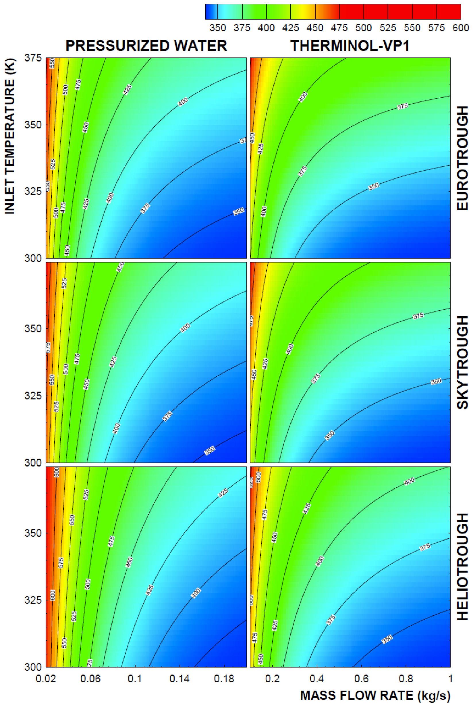
Figure 5 shows the contours of pressure drops (∆P/(1/2 ρV2): here, ΔP is the pressure drop in the absorber tube, is the working fluid density, and V is the working fluid inlet velocity) with the working fluid mass flow rates and inlet temperatures for the different troughs incorporated in the analysis. In general, pressure drops increased with increasing mass flow rates; however, fluid inlet temperature did not have a significant effect on the pressure drop. In addition, the pressure drop remained significantly smaller for pressurized water than for therminol-VP1. The pressure drop remained higher in the Euro trough than in the Sky and Helio troughs for each working fluid; however, the pressure drop in the Helio Trough remained lower than that of the Sky trough. Consequently, using the Helio Trough gave rise to low pressure drops for each working fluid, despite the fact that the first-law efficiency of the Helio Trough was lower than that corresponding to the Euro and Sky troughs. Figure 6 shows the contours of the working fluid outlet temperature with the working fluid mass flow rate and inlet temperature for two different fluid types. The working fluid outlet temperature reduced with reducing working fluid inlet temperatures and increased mass flow rates, which was more pronounced for pressurized water. Nevertheless, at high mass flow rates, the temperature difference between the working fluid inlet and exit temperature became about 25 °C, and the temperature difference increased with reducing working fluid mass flow rates. This finding was true for all of the troughs incorporated in the analysis. However, for a given mass flow rate, the Euro Trough resulted in improved working fluid outlet temperatures, followed by the Sky and Helio troughs. This behavior was true for both the pressurized water and therminol-VP1 fluids. Hence, the working fluid outlet temperature remained higher for the Euro Trough when a high mass flow rate of the working fluid was incorporated. The influence of the mass flow rate on fluid outlet temperature became similar for the Sky and Helio troughs for the therminol-VP1 fluid; however, this behavior changed for pressurized water. In this case, the working fluid outlet temperature became higher for the Helio Trough than the Sky Trough for a given mass flow rate and fluid inlet temperature.
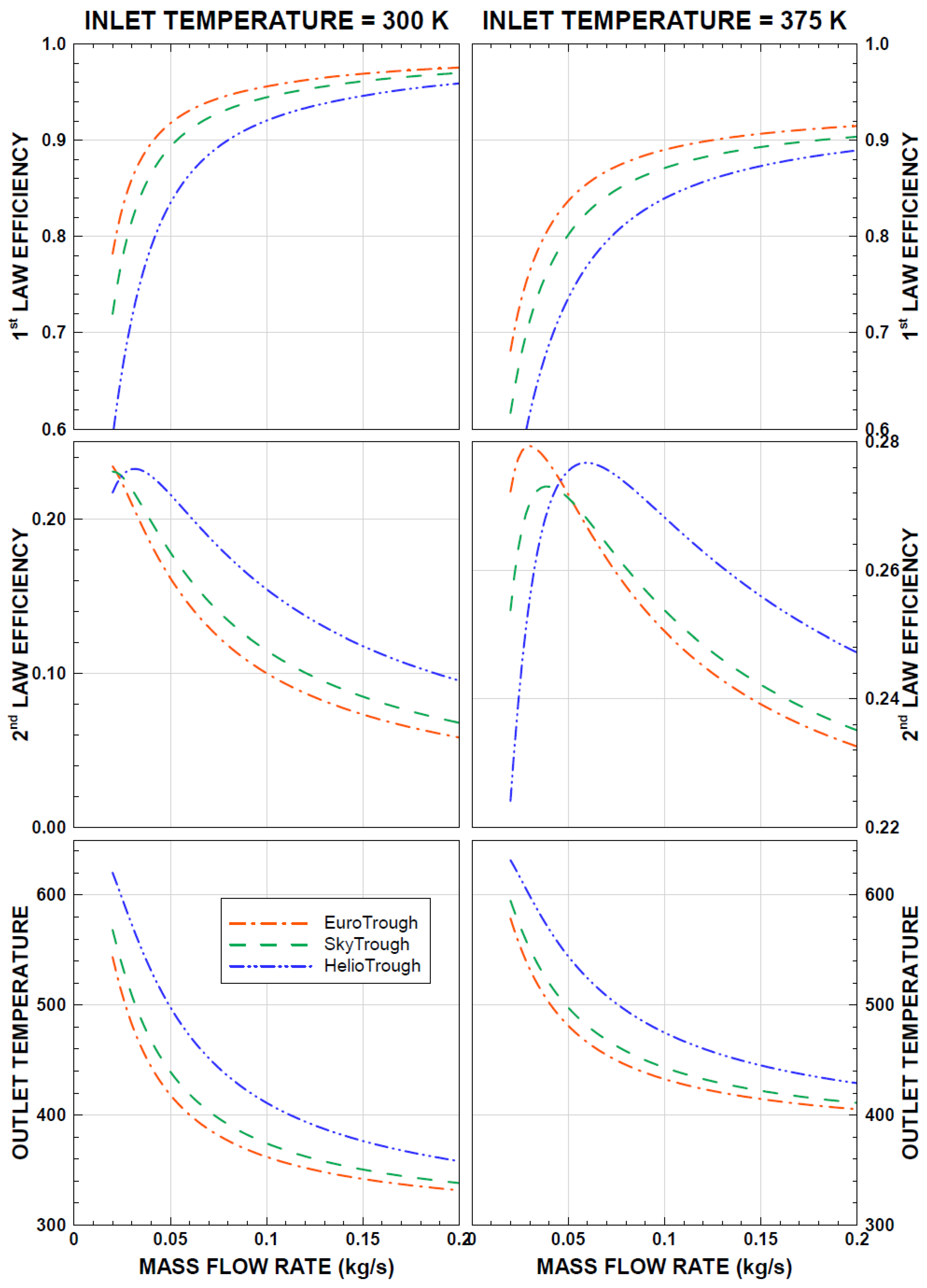
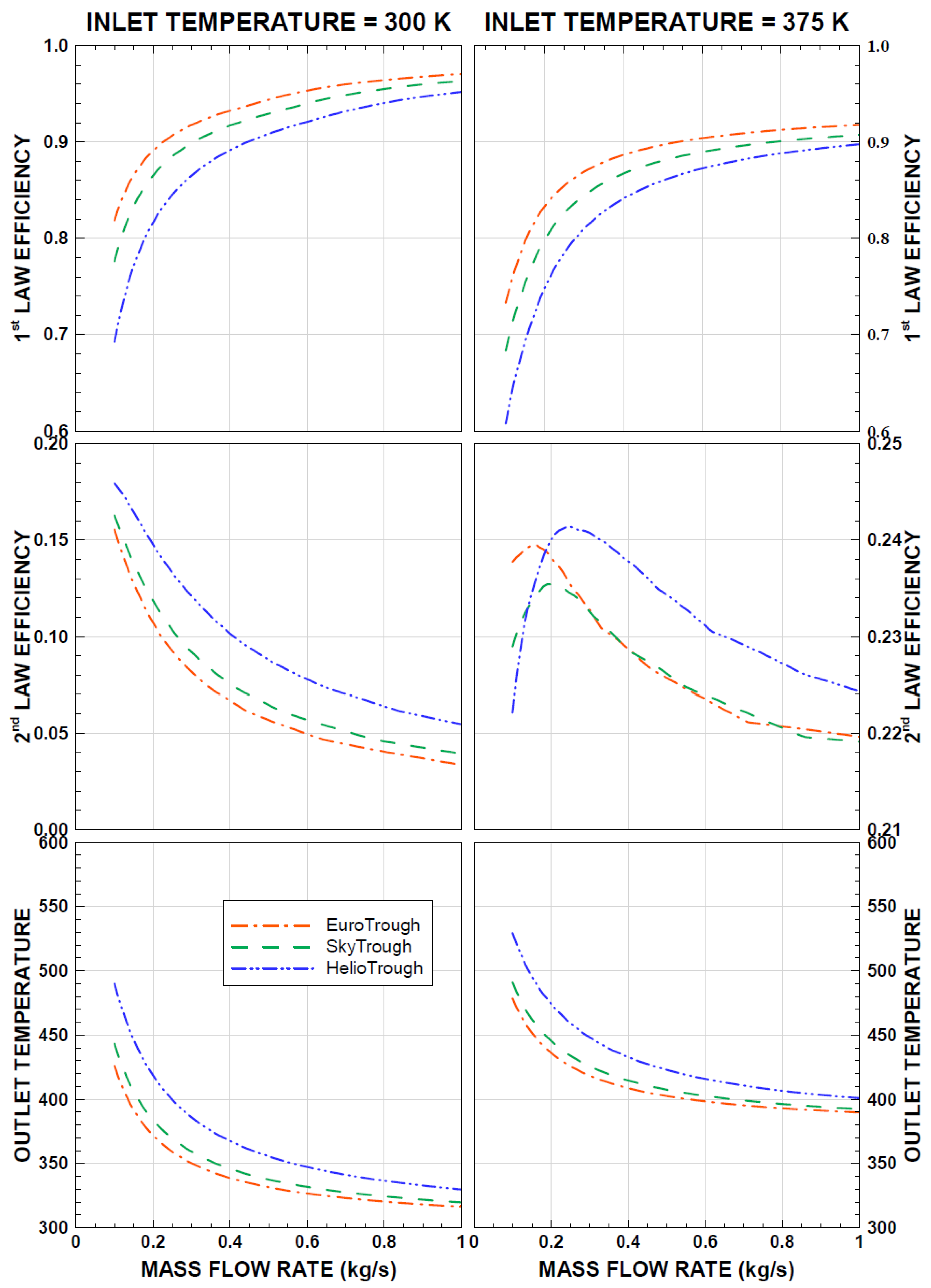
Figure 7 shows the first- and second-law efficiencies and outlet temperature of the working fluid for the Euro, Sky, and Helio troughs with a working fluid mass flow rate incorporating pressurized water for minimum and maximum working fluid inlet temperatures that were considered in this study. The first-law efficiency attained larger values for the low values of the working fluid inlet temperature than for the high inlet temperatures. This behavior was true for all of the troughs considered. This was associated with the heat input to the working fluid, which increased with low values of the working fluid inlet temperature. Hence, the energy gained by the working fluid increased while increasing the first-law efficiency. The increase of the first-law efficiency was sharp for a small range of mass flow rates (≤0.1 kg/s), and as the mass flow rate increased, the enhancement of the first-law efficiency became gradual, which was true for the Euro, Sky, and Helio troughs. The gradual increase of the first-law efficiency showed that when pressurized water was used as the working fluid, a large increase in the first-law efficiency could be obtained for a mass flow rate within the range of 0.1 kg/s; however, a further increase in the mass flow rate did not yield a substantial increase in the first-law efficiency. The first-law efficiency remained high for the Euro Trough, followed by the Sky and Helio troughs. Consequently, the Euro Trough demonstrated the highest performance in terms of the first-law efficiency. In addition, increasing inlet temperatures of the working fluid lowered the first-law efficiency almost 6% for all of the troughs incorporated. In the case of the second-law efficiency, low mass flow rates resulted in high values of the second-law efficiency for all troughs incorporated. Increasing mass flow rates lowered the second-law efficiency of the troughs. The second-law efficiency remained high for the Euro Trough when the working fluid mass flow rate remained low (≤0.02 kg/s), which was true for both low and high temperatures of the working fluid. The working fluid mass flow rate corresponding to the peak value of the second-law efficiency changed with the trough type: it increased slightly for the Helio Trough. The second-law efficiency reached its maximum at different mass flow rates, and this behavior changed with the working fluid inlet temperature. At a working fluid temperature of 375 K, the second-law efficiency reached its peak when the working fluid mass flow rate was 0.02 kg/s for the Euro Trough, and it became 0.035 kg/s for the Sky Trough and was 0.6 kg/s for the Helio Trough. Nevertheless, the peak value of the second-law efficiency was larger for the Euro Trough. The decay of the second-law efficiency from its peak value became relatively gradual for the Helio Trough compared to the other troughs. Consequently, selection of the Helio Trough provided a gradual change in the second-law efficiency when the working fluid mass flow rate was increased. Therefore, when operating the trough at high mass flow rates, the Helio Trough provided better performance in terms of the second-law efficiency than the Euro and Sky troughs did.
The performances of the Euro and Sky troughs at high working fluid inlet temperatures became almost same as the mass flow rate of the working fluid increased. However, this behavior differed as the mass flow rate reduces below 0.5 kg/s, in which case the Euro Trough gave rise to the highest second-law efficiency. In the case of the working fluid outlet temperature, the outlet temperature reduced sharply with increasing mass flow rates (≥0.06 kg/s), and the decay became gradual with further increases in the working fluid mass flow rate. The highest inlet temperature was selected at 375 K, which corresponded to the outlet temperature of the first trough in the series-connected trough system when the inlet temperature of the working fluid was 300 K. Hence, for an inlet temperature of 300 K, the trough outlet temperature reached 375 K for larger mass flow rates in the Helio Trough than in the Euro and Sky troughs. Consequently, using the Helio Trough at high mass flow rates allowed the second trough in the series operation to have high efficiencies. In addition, the second Helio Trough in the series connection resulted in higher outlet temperatures of the working fluid for large mass flow rates.
Figure 8 shows the first- and second-law efficiencies and outlet temperature of the working fluid with mass flow rates for the Euro, Sky, and Helio troughs when therminol-VP1 fluid was used. The behaviors of the first- and second-law efficiencies with the mass flow rate remained almost the same as those predicted for pressurized water (Figure 7). However, the maximum first- and second-law efficiencies for different troughs changed for the therminol-VP1 fluid. In that case, the first-law efficiency improved while the second-law efficiency reduced when therminol-VP1 fluid was used. This was true for all of the troughs considered. In addition, the outlet temperature of the working fluid attained lower values with therminol-VP1 fluid than with pressurized water.
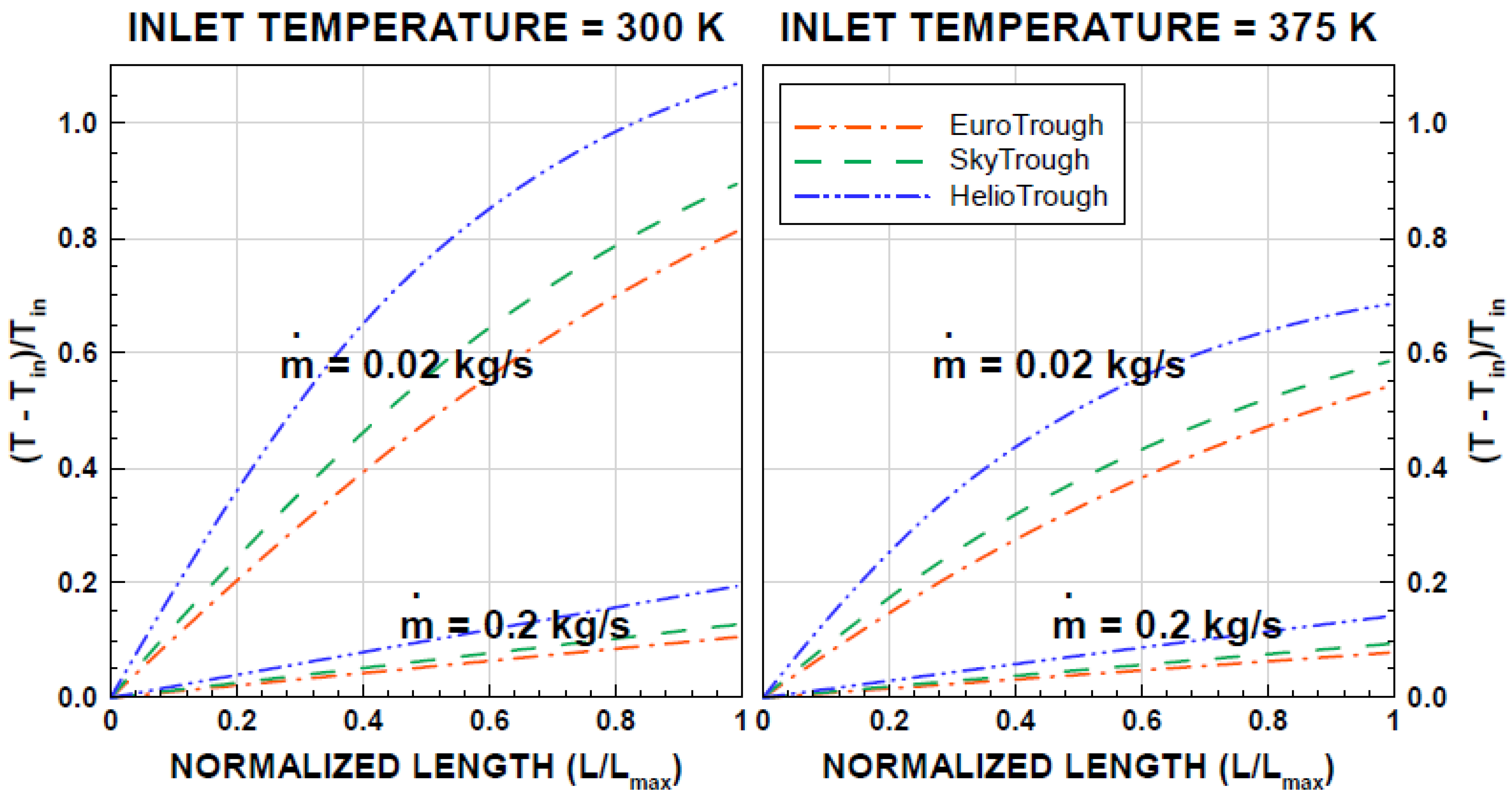
Figure 9 shows the normalized working fluid temperature difference ((T−Tin)/Tin, where T represents the working fluid temperature in the trough, and Tin is the working fluid inlet temperature) with the normalized trough length ((L/Lmax), where L is the length along the trough, and Lmax is the maximum length of the trough) for two working fluid mass flow rates. With higher values of length downstream of the flow, the normalized temperature difference was enhanced; however, the behavior of the temperature difference was in a parabolic form rather than in a linear form for the low mass flow rates of the working fluid. As the mass flow rate of the working fluid increased, this behavior became almost linear. The slope of the temperature difference changed with the trough types, in which case, the slope became largest for the Helio Trough, followed by the Sky and Euro troughs. In the case of low mass flow rates of the working fluid, the trough length reduced considerably for the maximum temperature difference, reaching 1.4 times the inlet temperature of the working fluid when the Helio Trough was used. This situation completely changed as the mass flow rate of the working fluid increased to 1 kg/s. Hence, the dimensionless trough length became almost the same, achieving similar maximum outlet temperatures for the Euro, Sky, and Helio troughs. Similar situations were also observed for a high inlet temperature (375 K) of the working fluid. The maximum temperature became almost 1.6 times the inlet temperature at the end of the trough length for low mass flow rates of the working fluid. Consequently, in terms of the temperature ratio, increasing working fluid temperatures at the trough exit became not as significant as the low inlet temperature was.
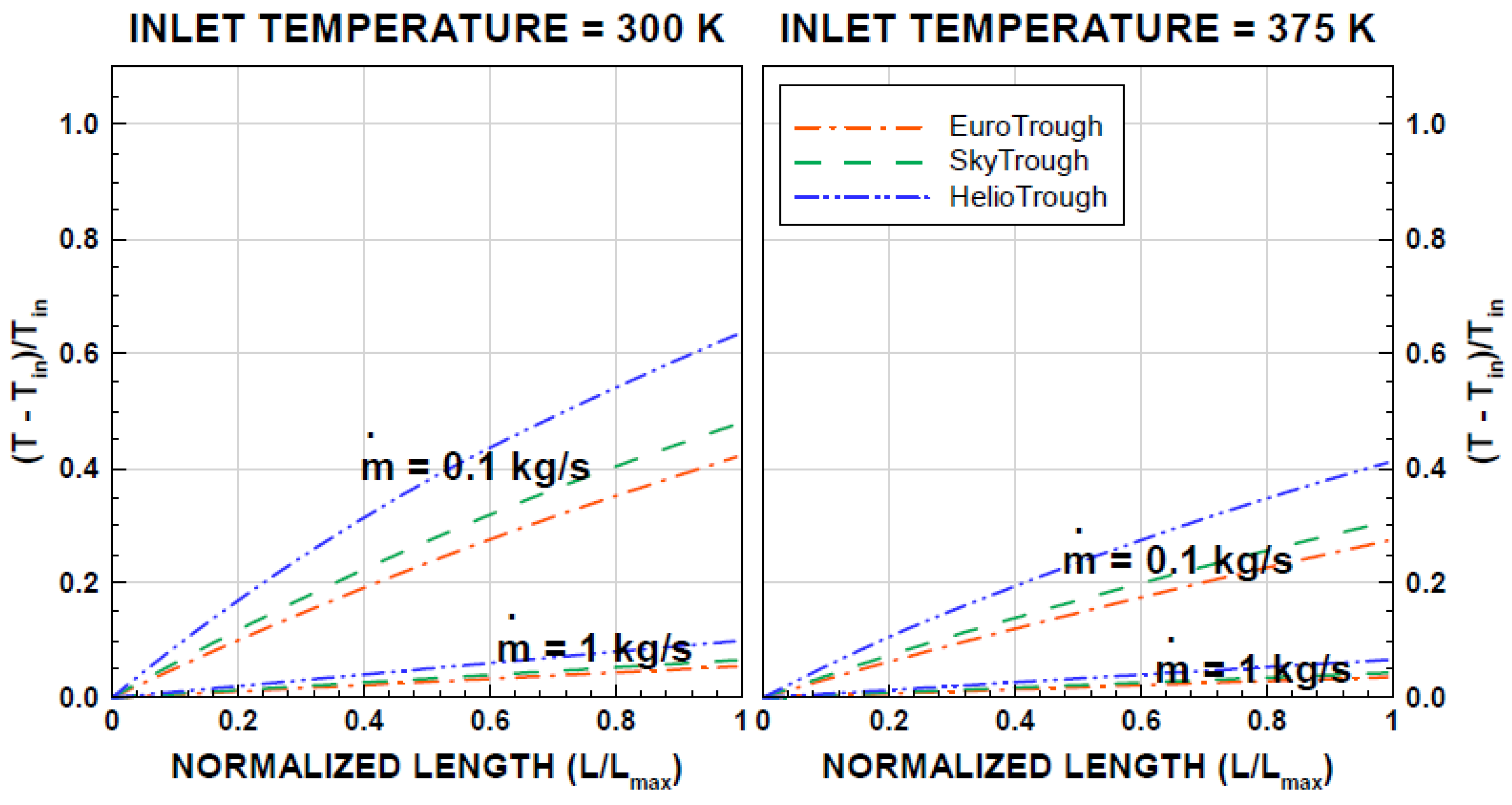
Figure 10 shows the normalized temperature difference of the working fluid for therminol-VP1 with the normalized trough length for two working fluid mass flow rates similar to those shown in Figure 9. The temperature difference behaved similarly to that of pressurized water (shown in Figure 9), provided that the temperature difference remained smaller for therminol-VP1 than for pressurized water. The normalized length (L/Lmax) of the trough increased to achieve 1.6 times the inlet fluid temperature for the working fluid of therminol-VP1: that is, the normalized temperature difference became almost half of that corresponding to pressurized water. Hence, the use of pressurized water lowered the normalized trough length to achieve the same temperature increase across the trough. This finding was true for all troughs incorporated in the analysis.
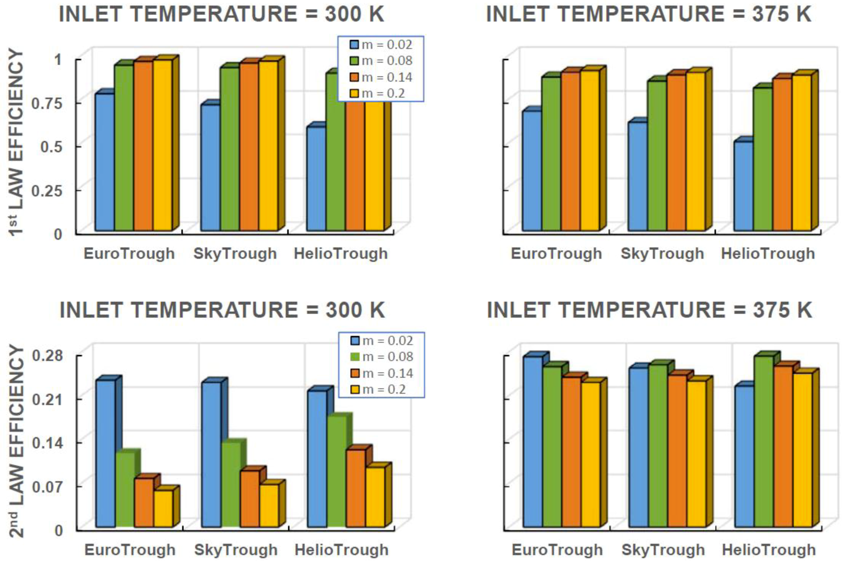
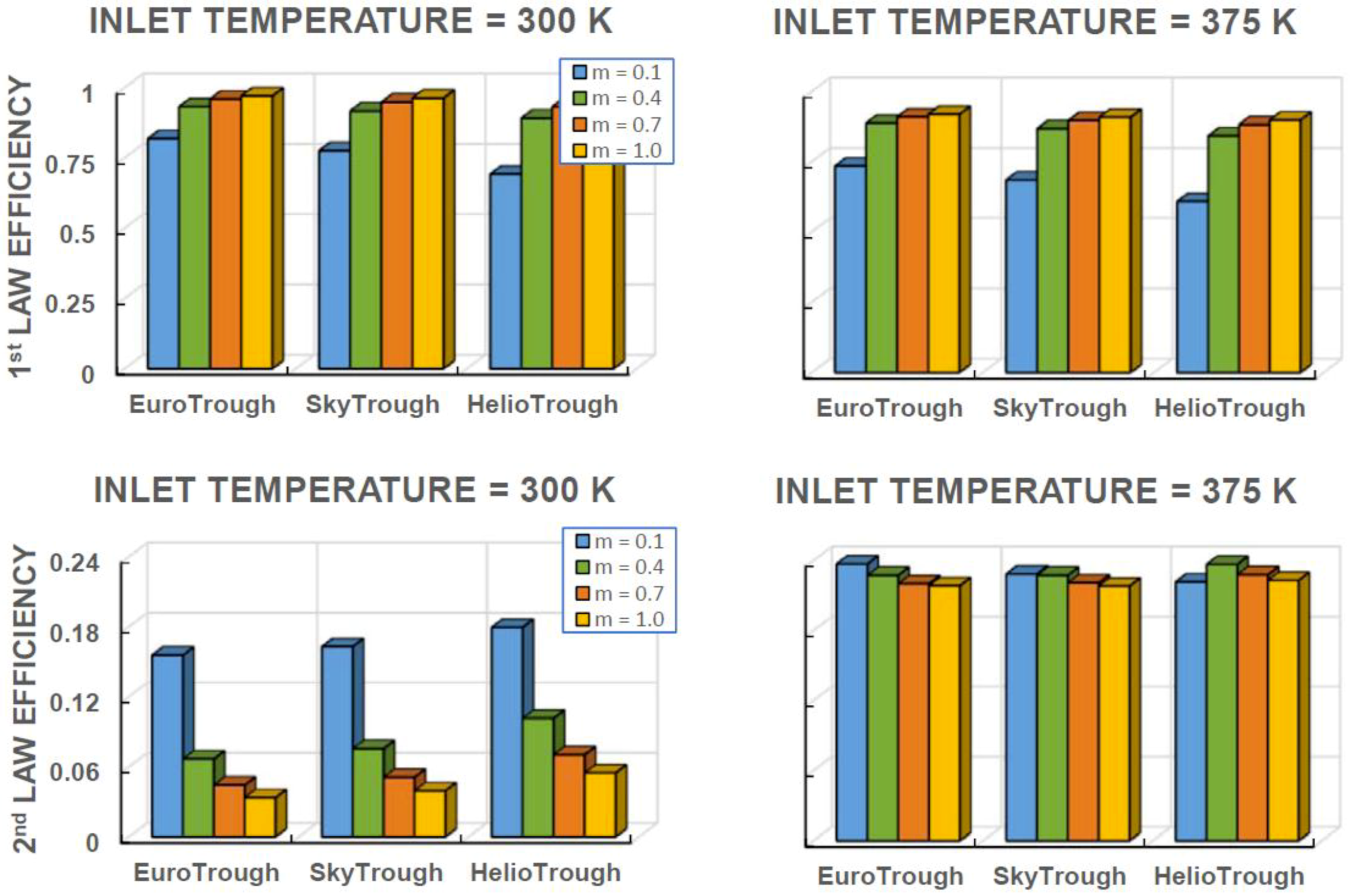
Figure 11 and Figure 12 show comparisons of the performances of the Euro, Sky, and Helio troughs in terms of the first- and second-law efficiencies for pressurized water and therminol-VP1. The comparison is provided for different mass flow rates to demonstrate the thermal performances of the troughs due to variations in the mass flow rate. The behavior of the first-law efficiency with the mass flow rate demonstrated a similar trend for all of the troughs considered. In that case, a low rate of mass flow lowered the first-law efficiency. However, the variation in the first-law efficiency became almost the same for mass flow rates ≥0.4 kg/s for therminol-VP1 and ≥0.08 kg/s for pressurized water, i.e., the first-law efficiency attained almost a steady value with more increases in the mass flow rate. Increasing the fluid inlet temperature lowered the first-law efficiency, which was more pronounced in the case of a low mass flow rate. The first-law efficiency attained slightly higher values for pressurized water than for the therminol-VP1 fluid. The Helio Trough resulted in the lowest first-law efficiency, which became more apparent for low mass flow rate cases (≥0.4 kg/s for therminol-VP1 and 0.08 kg/s for pressurized water). This behavior was true for low and high inlet temperature values (300 K and 375 K). On the other hand, the second-law efficiency attained higher values with reducing mass flow rates, which was more pronounced for low inlet temperatures of the working fluid (300 K). In addition, the second-law efficiency remained high and attained almost a steady value for a working fluid inlet temperature of 375 K, which was true for therminol-VP1 and pressurized water. In general, the Helio Trough resulted in slightly higher second-law efficiencies than the other troughs did. The second-law efficiency of pressurized water remained higher than that corresponding to therminol-VP1 fluid. Hence, operating troughs with therminol-VP1 fluid gave rise to relatively higher first-law efficiency than the other troughs did; however, the opposite was true for the second-law efficiency. The Helio Trough operating either at a high inlet temperature or a low mass flow rate gave rise to improved second-law efficiency. The Euro Trough operating either at high mass flow rates or low inlet temperatures resulted in higher first-law efficiency than the other troughs did.
4. Conclusions
The thermal performances of most commonly used solar troughs were analyzed in terms of the first-law and second-law efficiencies and the temperature rise in the working fluid. In this case, Euro, Sky, and Helio troughs were incorporated into the analysis. Pressurized water and therminol-VP1 were used as the working fluids in the thermal system. The influence of the fluid mass flow rate and inlet temperature on the trough performance was examined. The simulation results were validated with the data provided in an earlier study. It was found that the first-law efficiency predicted versus the dimensionless temperature was found to be in good agreement with the previous data. In general, an increasing mass flow rate enhanced the first-law efficiency; however, increasing the working fluid inlet temperature lowered the first-law efficiency. The pressurized water gave rise to higher first-law efficiency compared to therminol-VP1. The rise of the first-law efficiency with an increasing mass flow rate remained high for the low mass flow rate ranges. As the mass flow rate increased, the rise of the first-law efficiency became gradual. The Euro trough resulted in the highest first-law efficiency, followed by the Sky and Helio troughs. This was true for all of the mass flow rates and inlet temperatures of the working fluids that were incorporated. The second-law efficiency behaved oppositely to the first-law efficiency, where an increasing mass flow rate and inlet temperature of the working fluid lowered the second-law efficiency. The use of pressurized water gave rise to relatively higher second-law efficiency than the use of therminol-VP1 did. The Helio Trough gave rise to the highest second-law efficiency, followed by the Sky and Euro troughs. However, the second-law efficiency of the Sky and Euro troughs was almost same. The attainment of a high second-law efficiency for the Helio Trough is related to the outlet temperature, which is the highest for large mass flow rates compared to the Euro and Sky troughs. Consequently, using the Helio Trough at high mass flow rates would allow the second trough in a series operation to have high efficiencies. The temperature parameter ((T−Tin)/Tin) increased sharply along the Helio Trough’s length for all of the values of the mass flow rates considered. This yielded a shorter normalized trough length for the Helio Trough, achieving high working fluid temperatures at the trough exit. The pressure drop in the working fluid across the trough was the highest for the Euro Trough, followed by the Sky and Helio troughs. Consequently, the Helio Trough provided a high temperature rise along a normalized trough length, a low pressure drop in the working fluid across the trough, and the highest second-law efficiency despite the fact that the first-law efficiency remained the lowest compared to the Euro and Sky troughs. The present study provides insight into the thermal performance of the most commonly used parabolic solar troughs and provides useful comparative data in terms of the first- and second-law efficiencies, temperature rises, and pressure drops in the working fluid across the absorber tube length.
Author Contributions
Conceptualization, S.Z.S., B.S.Y., and H.A.-Q.; methodology, S.Z.S. and B.S.Y.; software, S.Z.S.; validation, S.Z.S., B.S.Y., and H.A.-Q.; formal analysis, B.S.Y. and H.A.-Q.; investigation, S.Z.S. and B.S.Y.; resources, H.A.-Q.; data curation, S.Z.S., B.S.Y., and H.A.-Q.; writing—original draft preparation, S.Z.S., B.S.Y., and H.A.-Q.; writing—review and editing, S.Z.S., B.S.Y., and H.A.-Q.; visualization, B.S.Y. and H.A.-Q.; funding acquisition.
Funding
This research was funded by the King Fahd University of Petroleum and Minerals, grant number RG171004, and the King Abdullah City for Atomic and Renewable Energy (K.A.CARE).
Acknowledgments
The authors acknowledge the support of the Deanship of Scientific Research, King Fahd University of Petroleum and Minerals, Dhahran, Saudi Arabia, via funding for the project RG171004, and the King Abdullah City for Atomic and Renewable Energy (K.A.CARE) for support.
Conflicts of Interest
The authors declare no conflict of interest. The authors also declare no personal circumstances or interest that may be perceived as inappropriately influencing the representation or interpretation of the reported research results. The funders had no role in the design of the study; in the collection, analyses, or interpretation of data; in the writing of the manuscript; or in the decision to publish the results.
References
- EuroTrough II: Extension, Test and Qualification of EuroTrough from 4 to 6 Segments at Plataforma Solar de Almeria. Available online: https://cordis.europa.eu/publication/rcn/6102_en.html (accessed on 21 April 2019).
- SkyTrough: Next Generation Solar Parabolic through Technology. Available online: http://www.Skyfuel.com/products/skytrough/ (accessed on 21 April 2019).
- TSK Flagsol. Available online: http://www.Heliotrough.com/ (accessed on 21 April 2019).
- Llamas, J.M.; Bullejos, D.; de Adana, M.R. Optimal operation strategies into deregulated markets for 50 MWe parabolic trough solar thermal power plants with thermal storage. Energies 2019, 125, 935. [Google Scholar] [CrossRef]
- Oles, A.S.; Jackson, G.S. Modeling of a concentrated-solar, falling-particle receiver for ceria reduction. Sol. Energy 2015, 122, 126–147. [Google Scholar] [CrossRef]
- Liao, Z.; Faghri, A. Thermal analysis of a heat pipe solar central receiver for concentrated solar power tower. Appl. Therm. Eng. 2016, 102, 952–960. [Google Scholar] [CrossRef]
- Zhu, Q.; Xuan, Y. Pore scale numerical simulation of heat transfer and flow in porous volumetric solar receivers. Appl. Therm. Eng. 2017, 120, 150–159. [Google Scholar] [CrossRef]
- Chen, X.; Xia, X.L.; Yan, X.W.; Sun, C. Heat transfer analysis of a volumetric solar receiver with composite porous structure. Energy Convers. Manag. 2017, 136, 262–269. [Google Scholar] [CrossRef]
- Reddy, K.S.; Nataraj, S. Thermal analysis of porous volumetric receivers of concentrated solar dish and tower systems. Renew. Energy 2019, 132, 786–797. [Google Scholar] [CrossRef]
- Wang, P.; Liu, D.Y.; Xu, C. Numerical study of heat transfer enhancement in the receiver tube of direct steam generation with parabolic trough by inserting metal foams. Appl. Energy 2013, 102, 449–460. [Google Scholar] [CrossRef]
- Kim, J.; Kim, J.S.; Stein, W. Simplified heat loss model for central tower solar receiver. Sol. Energy 2015, 116, 314–322. [Google Scholar] [CrossRef]
- Hussain, T.; Islam, M.D.; Kubo, I.; Watanabe, T. Study of heat transfer through a cavity receiver for a solar powered advanced Stirling engine generator. Appl. Therm. Eng. 2016, 104, 751–757. [Google Scholar] [CrossRef]
- Du, S.; Ren, Q.; He, Y.L. Optical and radiative properties analysis and optimization study of the gradually-varied volumetric solar receiver. Appl. Energy 2017, 207, 27–35. [Google Scholar] [CrossRef]
- Tu, N.; Wei, J.; Fang, J. Numerical study on thermal performance of a solar cavity receiver with different depths. Appl. Therm. Eng. 2014, 72, 20–28. [Google Scholar] [CrossRef]
- Chang, C.; Xu, C.; Wu, Z.Y.; Li, X.; Wang, Z.F. Heat transfer enhancement and performance of solar thermal absorber tubes with circumferentially non-uniform heat flux. Energy Procedia 2015, 69, 320–327. [Google Scholar] [CrossRef]
- Aichouba, A.; Merzouk, M.; Valenzuela, L.; Zarza, E.; Kasbadji-Merzouk, N. Influence of the displacement of solar receiver tubes on the performance of a parabolic-trough collector. Energy 2018, 159, 472–481. [Google Scholar] [CrossRef]
- Roldan, M.I.; Zarza, E.; Casas, J.L. Modelling and testing of a solar-receiver system applied to high-temperature processes. Renew. Energy 2015, 76, 608–618. [Google Scholar] [CrossRef]
- Dugaria, S.; Bortolato, M.; Del Col, D. Modelling of a direct absorption solar receiver using carbon based nanofluids under concentrated solar radiation. Renew. Energy 2018, 128, 495–508. [Google Scholar] [CrossRef]
- Sandlin, M.; Abdel-Khalik, S.I. An experimental and numerical study of granular flows through a perforated square lattice for central solar receiver applications. Sol. Energy 2018, 174, 463–473. [Google Scholar] [CrossRef]
- Chu, F.; Bai, S.; Zhang, X.; Yang, B.; Nie, F. Experimental study and thermal analysis of a tubular pressurized air receiver. Renew. Energy 2018, 125, 413–424. [Google Scholar] [CrossRef]
- Bianco, J.; Alarcon, D.; Sanchez, B.; Malato, S.; Maldonado, M.I. Technical comparison of different solar-assissted heat supply systems for a multi-effect seawater distillation unit. In Proceedings of the ISES Solar World Congress: Solar Energy for a Suitable Future, Göteborg, Sweden, 14–19 June 2003. [Google Scholar]
- Bellos, E.; TziVanidis, C.; Antonopoulos, K.A. A detailed working fluid investigation for solar parabolic trough. Appl. Therm. Eng. 2017, 114, 374–386. [Google Scholar] [CrossRef]
- Tzivanidis, C.; Bellos, E.; Korres, D.; Antonopoulos, K.A.; Mitsopoulos, G. Thermal and optical efficiency investigation of a parabolic trough collector. Case Stud. Therm. Eng. 2015, 6, 226–237. [Google Scholar] [Green Version]
- Bellos, E.; Korres, D.; Tzivanidis, C.; Antonopoulos, K.A. Design, simulation and optimization of a compound parabolic collector. Sustain. Energy Technol. Assess 2016, 16, 53–63. [Google Scholar] [CrossRef]
- Leinhard, J., IV; Leinhard, J., IV. Hat Transfer Textbook, 4th ed.; Philogiston Press: Cambridge, MA, USA, 2011; pp. 354–360. [Google Scholar]
- Bellos, E.; Tzivanidis, C.; Antonopoulos, K.A.; Daniil, I. The use of gas working fluids in parabolic trough collectors—An energetic and exergetic analysis. Appl. Therm. Eng. 2016, 109, 1–14. [Google Scholar] [CrossRef]
- Yazdanphanahi, J.; Sarhaddi, F.; Adeli, M.M. Experimental investigation of exergy efficiency of a solar photovoltaic thermal. Sol. Energy 2015, 118, 197–208. [Google Scholar] [CrossRef]
- Petela, R. Exergy analysis of solar radiation. In Solar Thermal Sciences and Engineering Applications; Enteria, N., Akbarzadeh, A., Eds.; CRC Press Taylor & Francis Group: Abington, UK, 2013; Chapter 2; pp. 120–210. [Google Scholar]
Figure 1.
A schematic view of the parabolic trough collector (PTC) used in the analysis.

Figure 2.
First-law efficiency of Euro Trough predicted and obtained from a previous work [21].
Figure 2.
First-law efficiency of Euro Trough predicted and obtained from a previous work [21].

Figure 3.
First-law efficiency of the Euro, Sky, and Helio troughs with working fluid mass flow rates for pressurized water and therminol-VP1.
Figure 3.
First-law efficiency of the Euro, Sky, and Helio troughs with working fluid mass flow rates for pressurized water and therminol-VP1.

Figure 4.
Second-law efficiency of the Euro, Sky, and Helio troughs with working fluid mass flow rates for pressurized water and therminol-VP1.
Figure 4.
Second-law efficiency of the Euro, Sky, and Helio troughs with working fluid mass flow rates for pressurized water and therminol-VP1.

Figure 5.
Pressure drops across absorbing tube in the Euro, Sky, and Helio troughs with working fluid mass flow rates for pressurized water and therminol-VP1.
Figure 5.
Pressure drops across absorbing tube in the Euro, Sky, and Helio troughs with working fluid mass flow rates for pressurized water and therminol-VP1.

Figure 6.
Outlet temperature of absorbing tube in the Euro, Sky, and Helio troughs with working fluid mass flow rates for pressurized water and therminol-VP1.
Figure 6.
Outlet temperature of absorbing tube in the Euro, Sky, and Helio troughs with working fluid mass flow rates for pressurized water and therminol-VP1.

Figure 7.
First- and second-law efficiencies and outlet temperature of the absorbing tube in the Euro, Sky, and Helio troughs with working fluid mass flow rates for two inlet temperatures of pressurized water.
Figure 7.
First- and second-law efficiencies and outlet temperature of the absorbing tube in the Euro, Sky, and Helio troughs with working fluid mass flow rates for two inlet temperatures of pressurized water.

Figure 8.
First- and second-law efficiencies and outlet temperature of the absorbing tube in the Euro, Sky, and Helio troughs with working fluid mass flow rates for two inlet temperatures of therminol-VP1.
Figure 8.
First- and second-law efficiencies and outlet temperature of the absorbing tube in the Euro, Sky, and Helio troughs with working fluid mass flow rates for two inlet temperatures of therminol-VP1.

Figure 9.
Dimensionless temperature along normalized length of the absorbing tube in the Euro, Sky, and Helio troughs with two mass flow rates and inlet temperatures of pressurized water.
Figure 9.
Dimensionless temperature along normalized length of the absorbing tube in the Euro, Sky, and Helio troughs with two mass flow rates and inlet temperatures of pressurized water.

Figure 10.
Dimensionless temperature along normalized length of the absorbing tube in the Euro, Sky, and Helio troughs with two mass flow rates and inlet temperatures of therminol-VP1.
Figure 10.
Dimensionless temperature along normalized length of the absorbing tube in the Euro, Sky, and Helio troughs with two mass flow rates and inlet temperatures of therminol-VP1.

Figure 11.
Comparison of first- and second-law efficiencies of the Euro, Sky, and Helio troughs due to different mass flow rates and for two inlet temperatures of pressurized water.
Figure 11.
Comparison of first- and second-law efficiencies of the Euro, Sky, and Helio troughs due to different mass flow rates and for two inlet temperatures of pressurized water.

Figure 12.
Comparison of first- and second-law efficiencies of the Euro, Sky, and Helio troughs due to different mass flow rates and for two inlet temperatures of therminol-VP1.
Figure 12.
Comparison of first- and second-law efficiencies of the Euro, Sky, and Helio troughs due to different mass flow rates and for two inlet temperatures of therminol-VP1.


| Collector | Euro Trough | Sky Trough | Helio Trough |
|---|---|---|---|
| Developer | European Consortium | Skyfuel USA | Flagsol GmbH |
| Aperture, () | 5.76 | 6 | 6.77 |
| Module length, () | 12 | 14 | 19.1 |
| Rim Angle, (θ°) | 80 | 82.5 | 89.5 |
| Focal length, () | 1.71 | 1.71 | 1.71 |
| Absorber tube diameter, () | 0.07 | 0.08 | 0.09 |
© 2019 by the authors. Licensee MDPI, Basel, Switzerland. This article is an open access article distributed under the terms and conditions of the Creative Commons Attribution (CC BY) license (http://creativecommons.org/licenses/by/4.0/).
Share and Cite
MDPI and ACS Style
Shuja, S.Z.; Yilbas, B.S.; Al-Qahtani, H. Thermal Assessment of Selective Solar Troughs. Energies 2019, 12, 3130. https://doi.org/10.3390/en12163130
AMA Style
Shuja SZ, Yilbas BS, Al-Qahtani H. Thermal Assessment of Selective Solar Troughs. Energies. 2019; 12(16):3130. https://doi.org/10.3390/en12163130
Chicago/Turabian StyleShuja, Shahzada Zaman, Bekir Sami Yilbas, and Hussain Al-Qahtani. 2019. "Thermal Assessment of Selective Solar Troughs" Energies 12, no. 16: 3130. https://doi.org/10.3390/en12163130
Note that from the first issue of 2016, this journal uses article numbers instead of page numbers. See further details here.