Detection of Inter-Turn Faults in Multi-Phase Ferrite-PM Assisted Synchronous Reluctance Machines


Electrical Engineering Department, Universitat Politècnica de Catalunya, 08222 Terrassa, Spain
*
Author to whom correspondence should be addressed.
Energies 2019, 12(14), 2733; https://doi.org/10.3390/en12142733
Submission received: 15 May 2019
/
Revised: 21 June 2019
/
Accepted: 15 July 2019
/
Published: 17 July 2019
(This article belongs to the Section E: Electric Vehicles)
Abstract
:Inter-turn winding faults in five-phase ferrite-permanent magnet-assisted synchronous reluctance motors (fPMa-SynRMs) can lead to catastrophic consequences if not detected in a timely manner, since they can quickly progress into more severe short-circuit faults, such as coil-to-coil, phase-to-ground or phase-to-phase faults. This paper analyzes the feasibility of detecting such harmful faults in their early stage, with only one short-circuited turn, since there is a lack of works related to this topic in multi-phase fPMa-SynRMs. Two methods are tested for this purpose, the analysis of the spectral content of the zero-sequence voltage component (ZSVC) and the analysis of the stator current spectra, also known as motor current signature analysis (MCSA), which is a well-known fault diagnosis method. This paper compares the performance and sensitivity of both methods under different operating conditions. It is proven that inter-turn faults can be detected in the early stage, with the ZSVC providing more sensitivity than the MCSA method. It is also proven that the working conditions have little effect on the sensitivity of both methods. To conclude, this paper proposes two inter-turn fault indicators and the threshold values to detect such faults in the early stage, which are calculated from the spectral information of the ZSVC and the line currents.
1. Introduction
Rare-earth permanent magnets (PMs) allow for the design of electric machines with appealing features, including high power and torque density, high efficiency or low rotor inertia [1]. However, due to factors such as supply risk concerns or the price fluctuation of rare-earth materials [2], the automotive sector is turning its interest towards machines requiring less rare-earth PMs or even to rare-earth-free electrical machines. Another possible strategy is to use recycled PMs obtained from end-of-life products [3]. Synchronous reluctance machines (SynRMs) have interesting characteristics for automotive applications, including high power and torque densities, due to the extra torque they produce due to the reluctance component [4], which adds to the alignment torque. To boost the features of SynRMs, they can also include ferrite-PMs, thus obtaining ferrite-PM-assisted SynRMs (fPMa-SynRMs), which are competing with PM synchronous machines and asynchronous machines [5,6,7] in several applications demanding high power density, high efficiency, overloading capability or a wide constant-power speed range [8]. Despite the relatively low magnetic properties when compared with rare-earth based magnets, ferrite PMs have several advantages, including their abundancy and low-cost. It is a recognized fact that fPMa-SynRMs offer higher reluctance torque compared to interior-PM motors (IPM), because fPMa-SynRMs require less PM volume than IPMs, since the main contribution to the total torque is the reluctance component [6]. However, the reluctance torque generates higher ripple in the output, although torque pulsations can be minimized by means of a suitable design, including rotor skewing, asymmetric flux barriers or selected rotor steps [5].
Faults in electrical machines could produce loss of system reliability, unscheduled shutdowns [9], important economic losses or even harmful effects to humans. Therefore, there is a growing demand for improved fault diagnosis approaches in electrical machines, in particular for high-performance applications [10]. This strategy ensures the safe and reliable operation of the plant, while greatly reducing unexpected and unscheduled fault occurrences, thus improving system availability and minimizing economic losses and the likelihood of accidents [11].
Rotating electric machines are designed with mechanical and electrical symmetry to maximize performance and efficiency and to minimize vibrations. When operating under faulty conditions this symmetry is lost, thus changing the magnitude or the shape of different machine signals, such as the electromotive force, line currents, vibrations profile or the temperature, among others [12]. Most of these faults generate specific patterns of such signals, so these changes can be used for fault diagnosis purposes.
Different fault diagnosis techniques have been analyzed in the technical literature, based on on-line or off-line approaches. Whereas off-line methods require the disconnection of the machine and sometimes the removal of some components, on-line diagnosis methods require the addition of specific sensors to acquire data from the machine during normal operation, although in some cases no extra sensors are required. Due to the extensive application of speed drives to control electrical machines, new alternatives for on-line fault detection are now possible, since they often include current and voltage sensors used for over-current/voltage protection and torque/current control, which can be used for fault diagnosis, thus decreasing hardware requirements [13]. Therefore, a simple alternative consists of an on-line acquisition of currents and voltages. Therefore, on-line diagnosis methods are generally preferred over off-line methods, due to their simplicity and accessibility [14].
As explained, a straightforward possibility for on-line fault diagnosis comes from the analysis of the currents and voltages acquired from the terminals of the machine, although other approaches are possible. Other methods found in the technical literature include a diversity of techniques based on the analysis of the electromechanical torque [15], changes in the variations in the main magnetic field [16], in the vibrations pattern [17] or in the input impedance [18], among others.
Motor current signature analysis (MCSA) is among the most popular fault detection and diagnosis methods, since it is a noninvasive method based on the analysis of the stator current patterns that can be applied for on-line fault diagnosis [19,20,21]. MCSA is a recognized set of techniques focused on diagnosing faults in rotating electrical machines [22]. MCSA is based on measuring and monitoring the line current of the machine and, by means of the fast Fourier transform (FFT) or similar techniques, calculating their spectra when the machine operates under steady-state or quasi-steady-state conditions. According to the MCSA philosophy, any change in some characteristic frequency harmonics of the line currents must be attributed to the effect of faults in the machine. MCSA has been applied to different types of electrical machines, including SynRMs [23], induction machines [22] and PM machines. The sensitivity of this method and the characteristic harmonic frequencies used for analysis could depend on the specific machine topology and the winding configuration [24]. As happens with other techniques, it is not free of false indications [25], some of them due to the influence of the curent current loop on the speed drive, which can affect the amplitude of the harmonic components of the line currents [24].
According to different works [13,24,26,27], inter-turn faults can be detected in their early stage by analyzing the zero-sequence voltage component (ZSVC). The analysis of the ZSVC is advantageous because, contrarily to what happens with the analysis of the line currents, the ZSVC is easily decoupled from the speed drive effects, although it requires an accessible neutral point of the stator windings, which is quite common in fault-tolerant machines [24]. For these reasons, some results found in the technical literature show that when dealing with PM synchronous machines, the fault diagnosis method based on the ZSVC tends to offer better sensitivity and accuracy than those of the MCSA [24,28].
This work focuses on the detection of inter-turn faults in five-phase fPMa-SynRMs by analyzing the spectra of the line currents and the ZSVC, which allows for a straightforward and powerful application of an on-line fault diagnosis approach. To gain understanding in such a topic, the finite element method (FEM) has been used to analyze the effects of such faults, because it is a recognized means for this purpose [28].
To the best of our knowledge, although the are several works dealing with the on-line detection of inter-turn faults in different machine types such as induction motors [29], switched reluctance machines [30], brushless DC machines [31] or PM synchronous motors [13], among others, there are virtually no works dealing with the on-line detection of inter-turn faults in synchronous reluctance machines, thus this work contributing in this area, and specifically in the area of fault diagnosis in multi-phase machines, in which the research done is even less. Results presented when dealing with only one shorted turn, show the feasibility of the proposed strategy to perform a very fast detection of inter-turn faults in the very early stage. It must be pointed out that nowadays there is a great interest in fPMa-SynRMs, in particular for propulsion machines for electromobility applications. However, due to the specific topology of fPMa-SynRMs, the detection of inter-turn faults can be an issue in these machines, and thus, the paper shows that by analyzing specific operating conditions, an early fault detection can be eased. This work also discusses the calculation of very fast fault indicators to detect early inter-turn faults in five-phase fPMa-SynRMs, this being another contribution of this paper.
This paper is organized as follows. Section 2 details the features and the topology of the analyzed fPMa-SynRM. Section 3 develops the FEM model used to analyze the machine and validates this model by means of experimental data. Section 4 develops the detection approaches based on the line currents and the ZSVC, whereas Section 5 shows all of the results attained. Section 6 develops the fault indicators used to detect incipient inter-turn faults, and finally, Section 7 draws the conclusions of this research work.
2. The Analyzed fPMa-SynRM
Table 1 summarizes the characteristics of the fPMa-SynRM dealt with in this work.
In order to limit the harmful effects of inter-turn faults, the fPMa-SynRM was designed to be fault-tolerant. To this end, it combines a low current design (4 A) and a winding type, in which each stator slot accommodates 60 conductors of the same phase, thus providing large inductances and electrical insulation among the different phases, as shown in Figure 1. However, the winding topology can notoriously influence the spectral composition of the back electromotive force (back-emf) and the magnetomotive force (mmf), and thus, such effects can be seen in the spectra of the ZSVC and the line currents [28].
Figure 1d shows that the quadrature axis (q-axis) corresponds to the minimum flux direction, i.e., the direction in which the magnetic flux crosses the air barriers. Contrarily, the direct axis (d-axis) corresponds to the direction of maximum magnetic flux, i.e., the direction of the magnetic flux along the magnetic path. It is worth noting that in fPMa-SynRMs, the PMs are magnetized opposite to the q-axis direction.
The direct- and quadrature-axis currents (id, iq) expressed in the d-q reference are easily calculated from the instantaneous values of the line currents (ia, ib, ic, id, ie) [6] as:
where Idq = [id iq]t, Iabcde = [ia ib ic id ie]t and A is given by:
where θ is the actual rotor position (d-axis) with respect to the reference phase a. The current angle αЄ (0°, 90°) is obtained as α = arctg (iq/id).
Idq = A·Iabcde
3. Validation of the FEM Model
This section validates the FEM model of the fPMa-SynRM by using experimental results. Once the FEM model has been built, the next step is to compare the experimental data with the results provided by the FEM model.
Table 2 summarizes the main parameters of the FEM model build with the Altair Flux 2018 software package.
Magnetic transient simulations (setting the initial rotor speed, the constant control angle α,) require about 72 h using an Intel® Core™ i9-7940X CPU @ 3.10 GHz with 64 GB RAM memory.
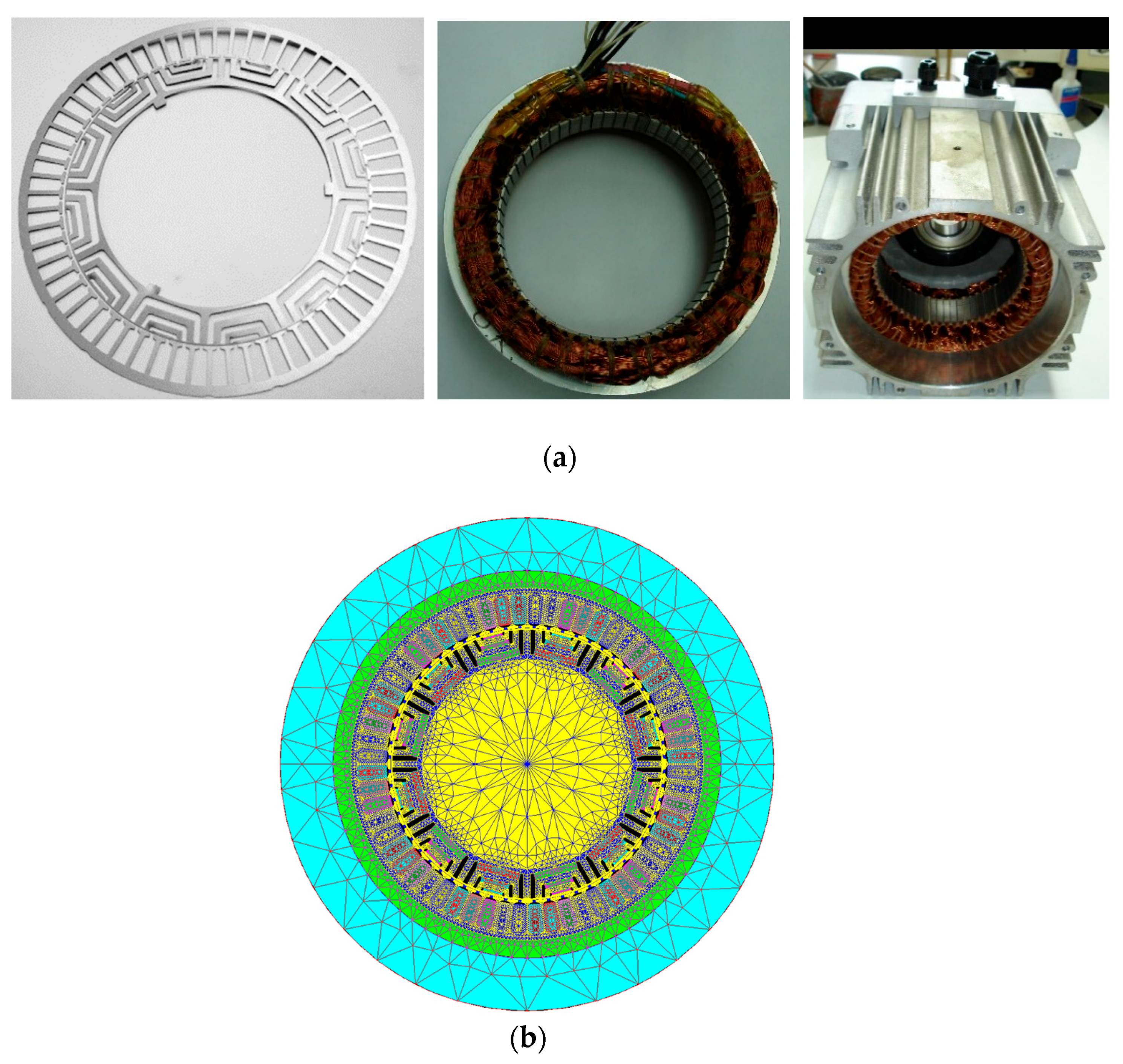
Figure 2 shows the fPMa-SynRM machine and the mesh of the FEM model.
In order to validate the FEM model, the machine shown in Figure 2a was tested at a constant speed of 1000 rev/min when working as a generator under no-load conditions. This condition was attained by connecting the analyzed fPMa-SynRM to a permanent magnet synchronous machine acting as a motor, as shown in Figure 3b. The analyzed fPMa-SynRM allows short-circuiting of one of the poles of phase a, as shown in Figure 3a.
The comparison between experimental and FEM results when the analyzed fPMa-SynRM operates under both healthy and faulty conditions (short-circuiting one pole of one of the phases), allows us to conclude that the FEM results are in good agreement with the experiments, although there are some minor differences. These differences can be attributed to different causes, such as small differences in the magnetization of the PMs in the real machine, or a slight asymmetry of the five windings due to end-coil effects in the real machine.
The experimental emf was acquired by means of a digital oscilloscope (Tektronix MDO3024 200 MHz 2.5 GS/s; Tektronix, Beaverton, OR, USA) connected to voltage probes (Tektronix TPP0250 250 MHz; Tektronix, Beaverton, OR, USA).
4. Detection of Inter-Turn Faults in fPMa-SynRMs by Analyzing the Spectra of the Stator Currents and the ZSVC
Inter-turn short-circuits are probably the most potentially critical faults in alternating current machines, since they can cause irreversible damage to the motor. Inter-turn short-circuit faults rapidly develop into more severe faults if not detected in the early stage, because they can progress fast into more severe short-circuit faults, such as coil-to-coil, phase-to-ground or phase-to-phase faults.
It has been proven that the magnitude of the circulating current within the shorted turns depends on several factors, including the number of shorted turns and the speed of the machine. It has been shown previously that the circulating fault current within the shorted turns increases linearly with the speed of the machine [13].
In this paper it is assumed that the fault condition can be detected from the comparison of a specific harmonic amplitude of the stator/line currents under healthy and faulty conditions [12]. By applying this approach, the harmonic frequencies leading to maximal differences between both conditions can be used to diagnose the state of the machine. It is worth noting that the speed drive supplying the fPMa-SynRM includes current sensors to measure the line currents, so they can also be used for fault diagnosis purposes.
As already explained, it has been proven that the speed drive that controls the machine can influence the amplitude of the harmonic components of the line currents, thus hindering the diagnosis based on this approach, which is a limitation of the MCSA. Therefore, the method based on the analysis of the harmonic content of the ZSVC is also analyzed in this paper.
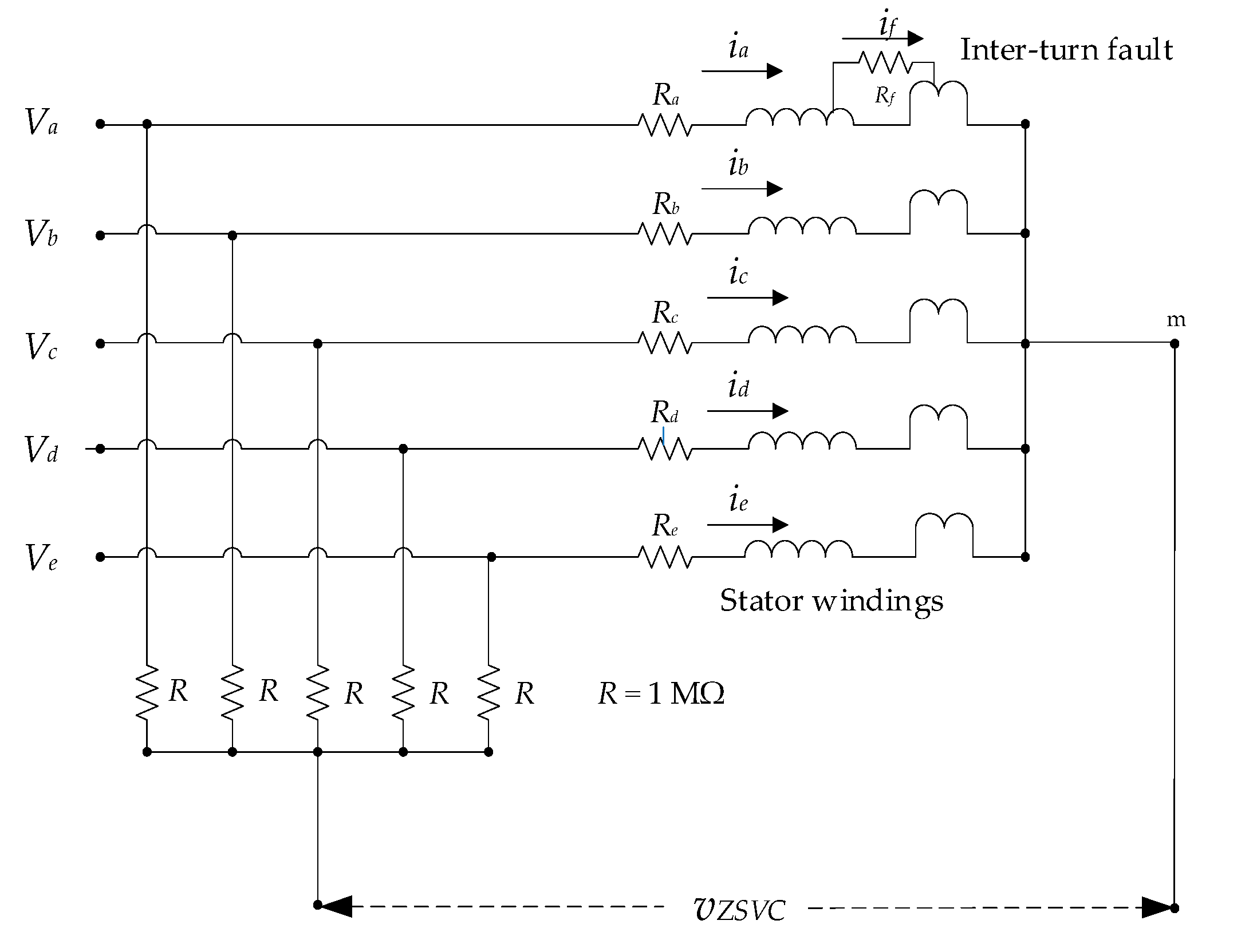
To apply a fault diagnosis approach based on the ZSVC, it is a requisite to have access to the neutral or central point of the stator windings [28], as shown in Figure 4. It is worth noting that fault-tolerant drives usually provide access to the neutral point, since they usually include an additional branch of the inverter to substitute the failed phase [32,33]. It has been shown previously that by connecting five identical resistors the ZSVC measured, as shown in Figure 4, becomes independent of the speed drive [34], i.e., any influence of the speed drive on the ZSVC is removed.
The instantaneous zero-sequence voltage component (vZSVC) in a healthy, and thus symmetric, fPMa-SynRM measured between the center of the stator windings and the artificial neutral point, as displayed in Figure 4, can be written as [34]:
where λPM is the instantaneous value of the zero-sequence component of the magnetic flux due to the PMs [34]:
When the machine operates under the effects of inter-turn faults, additional terms appear in Equation (3) because of the circulating fault current if (expressed as an instantaneous value), through the shorted turns, thus resulting in [13]:
where k1 and k2 are parameters which depend on the self- and mutual-inductances of the stator windings and the number of shorted turns.
In a previous work analyzing three-phase PMSMs, it is reported that the most relevant harmonic frequencies of the ZSVC when used to distinguish between faulty (inter-turn faults) and healthy machines, are the odd harmonics which are not multiples of three, the first harmonic being the most discriminant [13]. Therefore, it is expected that when dealing with five-phase fPMa-SynRMs, the harmonics used for analysis should be the odd harmonics which are not multiples of five, and specifically, the first odd harmonic frequencies.
5. Results
This section presents the results obtained by means of the FEM simulations considering two cases, i.e., when the machine operates under healthy and faulty conditions. The faulty condition is simulated as only one short-circuited turn in one of the phases, since the purpose of the paper is to detect early inter-turn faults, as shown in Figure 1c. The FEM model dealt with is described in detail in Section 3. FEM simulations are based on a sampling frequency of 100 kHz, thus having 200 samples per electrical period. Twenty full periods are simulated, which are repeated to obtain a total of 2000 periods for further post processing.
The following subsections present the results attained under rated conditions, i.e., when the saturation effects were non-negligible, and under low-load conditions, when the saturation effects were negligible. This was done to evaluate if the operating conditions affected the performance of the proposed approach.
5.1. The Analyzed Machine Operating under Low-Load Conditions
This section conducts a first analysis focused on detecting incipient inter-turn faults when the machine operates under low-saturation conditions. To this end, the fPMa-SynRM was analyzed when operating at 130 VRMS, 0.7 ARMS and 5000 rev/min, with a current angle of α = 30°, assuming that the d-axis corresponds to 0° and the q-axis to 90°. Therefore, id = iline,peak,1·cos30° and iq = iline,peak,1·sin30°, where iline,peak,1 refers to the peak value of the fundamental harmonic of the line current. This operating condition corresponds to 17.5% of the rated current, thus producing low magnetic saturation in the segments of the rotor. Figure 5 summarizes the results obtained by analyzing the spectral content of the line currents and the ZSVC.
Under low-load conditions, due to the small line currents, the rotor segments are almost not saturated, so the reluctance of the rotor path is also low. When the motor is positioned close to the d-axis, there is very little influence on the PMs, and thus, the reluctance of the rotor path is much lower than that of the air gap.
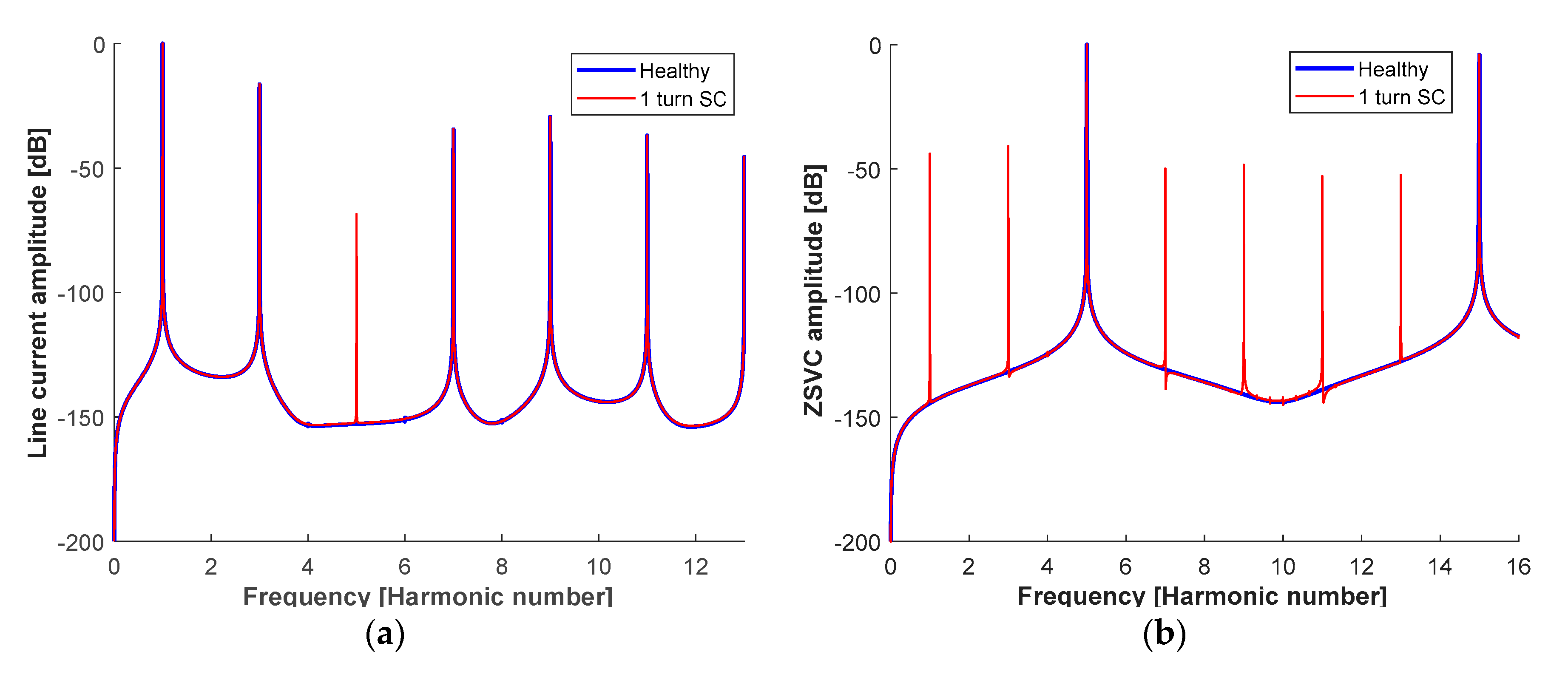
The results presented in Figure 5a show that the only appreciable change in the harmonic content of the line currents between a healthy and a faulty machine is in the fifth harmonic, which can be attributed to the unbalance of the line currents, with this effect being induced by the shorted turn.
From the analysis of the spectral content of the ZSVC (see Figure 5b) it can be deduced that different harmonics appear due to the shorted turn, specifically the odd harmonics which are not multiples of five, thus facilitating the detection of such damaging faults.
It should be noted that both the stator currents and ZSVC spectra are normalized with respect to the maximum value of the respective waveforms, that is, the amplitude or peak value of the fundamental harmonic can be written as follows:
where iFFT and vZSVC,FFT are the spectral data of the line currents and the vZSVC provided by the fast Fourier transform (FFT) algorithm, respectively, and iFFT,1 and vZSVC,FFT,1 are the amplitudes of the fundamental harmonics of the line currents and vZSVC, respectively.
In order to check a different operating condition, the next section analyzes the fPMa-SynRM under operating conditions in which the rotor segments are more saturated, i.e., under rated conditions.
5.2. The Analyzed Machine Operating under Rated Conditions
This section conducts a first analysis focused on detecting incipient inter-turn faults when the machine operates under rated conditions. According to the data provided in Table 1, the rated current and voltage are 4 ARMS and 240 VRMS, respectively, thus resulting in a rated power of 3.5 kW at 5000 rev/min. It should be noted that the current angle is 65°, assuming that the d-axis corresponds to 0° and the q-axis to 90°. This operating condition is defined by id = iline,rated,peak,1·cos65° and iq = iline,rated,peak,1·sin65°, where iline,rated,peak,1 refers to the rated peak value of the fundamental harmonic of the line current. Figure 6 summarizes the results attained under these operating conditions for both the line currents and the ZSVC.
The results presented in Figure 6a show that, similar to the results obtained under low-saturation conditions, the fifth harmonic of the line current appears in the faulty machine due to the unbalance of the line currents produced by the inter-turn fault.
Once again, when analyzing the spectral content of the ZSVC of the faulty machine, different new harmonic frequencies appear when compared with the healthy one, in particular the odd harmonic frequencies which are not multiples of five, as occurred under the low-load conditions.
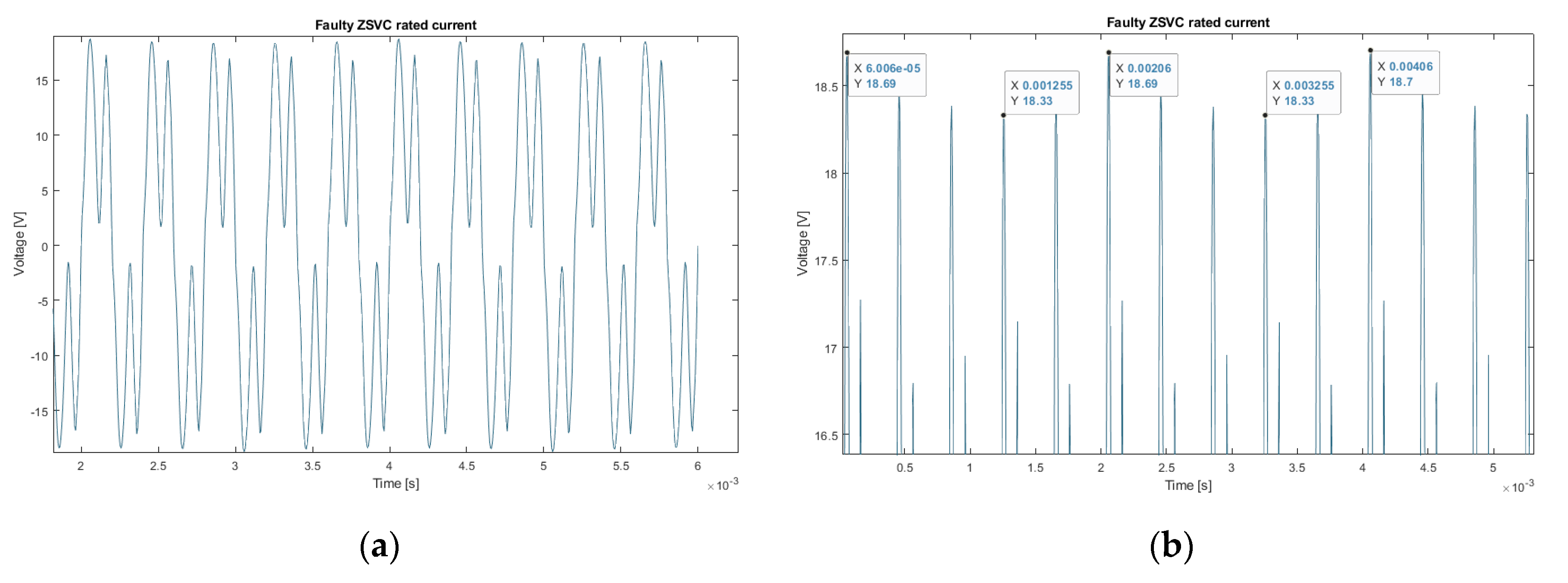
The results summarized in Figure 5b and Figure 6b prove a superior discrimination potential of the diagnosis method based on the analysis of the spectral content of the ZSVC. Such figures also indicate the presence of the odd harmonics in the ZSVC spectrum of the faulty machine. Such harmonics emerge because the voltage of the neutral point oscillates at 500 Hz due to the fault condition, i.e., the electrical frequency, as shown in Figure 7.
5.3. Summary of the Results Obtained
The next tables summarize the results obtained in the previous subsections for a better interpretation.
Table 3 and Table 4 highlight the most favorable conditions (gray shades) and harmonics (bold letters) to diagnose a faulty condition. It can be noted that when analyzing the spectrum of the ZSVC it is also possible to analyze the odd harmonics which are not multiples of five, i.e., the third, seventh, ninth, eleventh or thirteenth, among others.
In summary, it is suggested to analyze the fifth harmonic of the line current and the odd harmonics of the ZSVC spectrum. Is should be noted that the diagnosis approach based on the analysis of the harmonic content of the ZSVC shows improved sensitivity when compared with that of the line currents, since when analyzing the ZSVC the fault harmonics present higher relative amplitudes than those of the line currents.
6. Indicators to Diagnose Early Inter-Turn Faults
The results presented in Section 5 allow for the proposal of a fault diagnosis strategy to detect early inter-turn faults in multi-phase fPMa-SynRMs. To this end, this section proposes two fault indicators which are based on the analysis of the spectral content of the line currents and the ZSVC, respectively. The calculation process of such indicators is shown in Figure 8.
Both fault indicators shown in Figure 8 can be used to diagnose the health status of the machine. It is also possible to only use the fault indicator based on the ZSVC, since it provides more sensitivity. These fault indicators are based on the amplitude difference between two harmonics of the line currents or the ZSVC, therefore providing more discriminating power as seen in Table 3 and Table 4, respectively.
This method can be used to apply an on-line fault detection approach, because both the line currents and the ZSVC can be acquired in real-time, to further calculate the FFT of the line current and ZSVC signals, which is very fast since it requires about 1.2 ms with an Intel® Core™ i9-7940X CPU @ 3.10 GHz with 64 GB RAM.
7. Conclusions
Inter-turn winding faults are of great concern in electrical machines, and especially in PM machines, since while rotating, the induction effect generated by the PMs aggravates the consequences of such faults. This work studied a method to detect inter-turn faults in five-phase fPMa-SynRMs in their early stage by analyzing the spectral content of the line currents and the ZSVC under different operating conditions. It has been proven that it is feasible to detect such faults in the early stage using both methods, although the detection method based on the spectral content of the ZSVC is more versatile and provides improved sensitivity when compared with the method based on the spectrum of the line currents. The results presented in this paper show that inter-turn faults generate a fifth harmonic in the line currents and odd harmonic frequencies in the spectrum of the ZSVC. The results presented also prove that the operating conditions have little impact on the sensitivity of both methods. This paper has also proposed two simple and fast-to-calculate inter-turn fault indicators that are compatible with an on-line detection fault diagnosis approach. They are based on comparing the amplitudes of the fifth harmonic of the line currents and the first harmonic of the ZSVC against a threshold value.
The results of this research work may be appropriate to develop advanced fault diagnosis approaches for multi-phase fPMa-SynRMs, which can be applied for automotive applications, among others.
Author Contributions
Conceived and designed the experiments, C.C.-Z. and J.-R.R.; performed the experiments, C.C.-Z.; analyzed the data, C.L.-T. and A.G.; wrote the paper, J.-R.R.
Funding
This research and the APC were funded in part by the Spanish Ministry of Economy and Competitiveness, grant number TRA2016-80472-R and by the Generalitat de Catalunya, grant number 2017SGR0967.
Conflicts of Interest
The authors declare no conflict of interest.
Nomenclature
| ia,b,c,d,e | Instantaneous value of the phase current (A) |
| if | Instantaneous value of the fault current (A) |
| id | d-axis current (A) |
| iq | q-axis current (A) |
| iline,rated,peak,1 | Rated peak value of the fundamental harmonic of the line current (A) |
| iFFT | Spectral data of the line current provided by the FFT algorithm (A) |
| iline,peak,1 | Peak value of the fundamental harmonic of the line current (A) |
| iFFT,1 | Peak value of the fundamental harmonic of the line current (A) |
| va,b,c,d,e | Instantaneous value of the phase voltage (V) |
| vZSVC | Instantaneous value of the homopolar voltage (V) |
| vZSVC,FFT | Spectral data of the vZSVC provided by the FFT algorithm (V) |
| vZSVC,FFT,1 | Peak value of the fundamental harmonic of the vZSVC (V) |
| fs | Electrical frequency (Hz) |
| k | Harmonic number (-) |
| p | Pole pairs (-) |
| λPM | Instantaneous value of the zero-sequence component of the flux linkage due to the permanent magnets (Wb) |
| λa,b,c,d,c | Instantaneous value of the flux linkage in phases a,b,c,d,e due to permanent magnets (Wb) |
| Ra,b,c,d,e | Phase resistance (Ω) |
| θ | Rotor position (electrical °) |
| α | Current angle (electrical °) |
| FFT | Fast Fourier transform |
| fPMa-SynRM | Ferrite-assisted synchronous reluctance motor |
| IPM | Interior-PM motor |
| MCSA | Motor current signature analysis |
| PM | Permanent magnet |
| ZSVC | Zero-sequence voltage component |
| back-emf | Back-electromotive force |
| mmf | Magnetomotive force |
References
- Riba, J.-R.; López-Torres, C.; Romeral, L.; Garcia, A. Rare-earth-free propulsion motors for electric vehicles: A technology review. Renew. Sustain. Energy Rev. 2016, 57, 367–379. [Google Scholar] [CrossRef] [Green Version]
- Zhu, X.; Wu, W.; Quan, L.; Xiang, Z.; Gu, W. Design and Multi-Objective Stratified Optimization of a Less-rare-earth Hybrid Permanent Magnets Motor with High Torque Density and Low Cost. IEEE Trans. Energy Convers. 2018. [Google Scholar] [CrossRef]
- Kimiabeigi, M.; Sheridan, R.S.; Widmer, J.D.; Walton, A.; Farr, M.; Scholes, B.; Harris, I.R. Production and Application of HPMS Recycled Bonded Permanent Magnets for a Traction Motor Application. IEEE Trans. Ind. Electron. 2018, 65, 3795–3804. [Google Scholar] [CrossRef]
- Zhao, W.; Chen, D.; Lipo, T.A.; Kwon, B.-I. Performance Improvement of Ferrite-Assisted Synchronous Reluctance Machines Using Asymmetrical Rotor Configurations. IEEE Trans. Magn. 2015, 51, 1–4. [Google Scholar]
- Bonthu, S.S.R.; Choi, S.; Baek, J. Design of five-phase permanent magnet assisted synchronous reluctance motor for low output torque ripple applications. IET Electr. Power Appl. 2016, 10, 339–346. [Google Scholar] [CrossRef]
- López-Torres, C.; Riba, J.-R.; Garcia, A.; Romeral, L. Detection of eccentricity faults in five-phase ferrite-PM assisted synchronous reluctance machines. Appl. Sci. 2017, 7, 565. [Google Scholar] [CrossRef]
- Bolognani, S.; Mahmoud, H.; Bianchi, N. Fast synthesis of permanent magnet assisted synchronous reluctance motors. IET Electr. Power Appl. 2016, 10, 312–318. [Google Scholar]
- Mahmoud, H.; Bianchi, N. Eccentricity in Synchronous Reluctance Motors-Part I: Analytical and Finite-Element Models. IEEE Trans. Energy Convers. 2015, 30, 745–753. [Google Scholar] [CrossRef]
- Gupta, R.A.; Wadhwani, A.K.; Kapoor, S.R. Early Estimation of Faults in Induction Motors Using Symbolic Dynamic-Based Analysis of Stator Current Samples. IEEE Trans. Energy Convers. 2011, 26, 102–114. [Google Scholar] [CrossRef]
- Lee, H.; Jeong, H.; Kim, S.W. Diagnosis of Interturn Short-Circuit Fault in PMSM by Residual Voltage Analysis. In Proceedings of the 2018 International Symposium on Power Electronics, Electrical Drives, Automation and Motion (SPEEDAM), Amalfi, Italy, 20–22 June 2018; pp. 160–164. [Google Scholar]
- Akar, M. Detection of a static eccentricity fault in a closed loop driven induction motor by using the angular domain order tracking analysis method. Mech. Syst. Signal Process. 2013, 34, 173–182. [Google Scholar] [CrossRef]
- Faiz, J.; Jafari, A. Interturn fault diagnosis in brushless direct current motors—A review. In Proceedings of the 2018 IEEE International Conference on Industrial Technology (ICIT), Lyon, France, 20–22 Feburary 2018; pp. 437–444. [Google Scholar]
- Urresty, J.-C.; Riba, J.-R.; Romeral, L. Application of the zero-sequence voltage component to detect stator winding inter-turn faults in PMSMs. Electr. Power Syst. Res. 2012, 89, 38–44. [Google Scholar] [CrossRef]
- Romary, R.; Demian, C.; Schlupp, P.; Roger, J.-Y. Offline and Online Methods for Stator Core Fault Detection in Large Generators. IEEE Trans. Ind. Electron. 2013, 60, 4084–4092. [Google Scholar] [CrossRef]
- Maraaba, L.; Al-Hamouz, Z.; Abido, M.; Maraaba, L.; Al-Hamouz, Z.; Abido, M. An Efficient Stator Inter-Turn Fault Diagnosis Tool for Induction Motors. Energies 2018, 11, 653. [Google Scholar] [CrossRef]
- Wu, Y.; Ma, G.; Wu, Y.; Ma, G. Anti-Interference and Location Performance for Turn-to-Turn Short Circuit Detection in Turbo-Generator Rotor Windings. Energies 2019, 12, 1378. [Google Scholar] [CrossRef]
- Chang, H.-C.; Jheng, Y.-M.; Kuo, C.-C.; Hsueh, Y.-M.; Chang, H.-C.; Jheng, Y.-M.; Kuo, C.-C.; Hsueh, Y.-M. Induction Motors Condition Monitoring System with Fault Diagnosis Using a Hybrid Approach. Energies 2019, 12, 1471. [Google Scholar] [CrossRef]
- Park, J.-K.; Jeong, C.-L.; Lee, S.-T.; Hur, J. Early Detection Technique for Stator Winding Inter-Turn Fault in BLDC Motor Using Input Impedance. IEEE Trans. Ind. Appl. 2015, 51, 240–247. [Google Scholar] [CrossRef]
- Giantomassi, A.; Ferracuti, F.; Iarlori, S.; Ippoliti, G.; Longhi, S. Electric Motor Fault Detection and Diagnosis by Kernel Density Estimation and Kullback-Leibler Divergence Based on Stator Current Measurements. IEEE Trans. Ind. Electron. 2015, 62, 1770–1780. [Google Scholar] [CrossRef]
- Choi, S.; Haque, M.S.; Arafat, A.; Toliyat, H. Detection and Estimation of Extremely Small Fault Signature by Utilizing Multiple Current Sensor Signals in Multiphase Electric Machines. IEEE Trans. Ind. Appl. 2017, 53, 2805–2816. [Google Scholar] [CrossRef]
- Bouzida, A.; Touhami, O.; Ibtiouen, R.; Belouchrani, A.; Fadel, M.; Rezzoug, A. Fault Diagnosis in Industrial Induction Machines Through Discrete Wavelet Transform. IEEE Trans. Ind. Electron. 2011, 58, 4385–4395. [Google Scholar] [CrossRef]
- Huang, B.; Feng, G.; Tang, X.; Gu, J.X.; Xu, G.; Cattley, R.; Gu, F.; Ball, A.D.; Huang, B.; Feng, G.; et al. A Performance Evaluation of Two Bispectrum Analysis Methods Applied to Electrical Current Signals for Monitoring Induction Motor-Driven Systems. Energies 2019, 12, 1438. [Google Scholar] [CrossRef]
- Ilamparithi, T.; Nandi, S. Analysis, modeling and simulation of static eccentric reluctance synchronous motor. In Proceedings of the 8th IEEE Symposium on Diagnostics for Electrical Machines, Power Electronics & Drives, Bologna, Italy, 5–8 September 2011; pp. 45–50. [Google Scholar]
- Saavedra, H.; Urresty, J.-C.; Riba, J.-R.; Romeral, L. Detection of interturn faults in PMSMs with different winding configurations. Energy Convers. Manag. 2014, 79, 534–542. [Google Scholar] [CrossRef]
- Lee, S.B.; Hyun, D.; Kang, T.; Yang, C.; Shin, S.; Kim, H.; Park, S.; Kong, T.-S.; Kim, H.-D. Identification of False Rotor Fault Indications Produced by Online MCSA for Medium-Voltage Induction Machines. IEEE Trans. Ind. Appl. 2016, 52, 729–739. [Google Scholar] [CrossRef]
- Urresty, J.-C.; Riba, J.-R.; Romeral, L.; Ortega, J.A. Mixed resistive unbalance and winding inter-turn faults model of permanent magnet synchronous motors. Electr. Eng. 2014, 97, 75–85. [Google Scholar] [CrossRef] [Green Version]
- Saavedra, H.; Riba, J.-R.; Romeral, L. Detection of inter-turn faults in five-phase permanent magnet synchronous motors. Adv. Electr. Comput. Eng. 2014, 14, 49–54. [Google Scholar] [CrossRef]
- Urresty, J.-C.; Riba, J.-R.; Romeral, L. Influence of the stator windings configuration in the currents and zero-sequence voltage harmonics in permanent magnet synchronous motors with demagnetization faults. IEEE Trans. Magn. 2013, 49, 4885–4893. [Google Scholar] [CrossRef]
- Solodkiy, E.; Dadenkov, D.; Salnikov, S. Detection Of Stator Inter-turn Short Circuit In Three-Phase Induction Motor Using Current Coordinate Transformation. In Proceedings of the 2019 26th International Workshop on Electric Drives: Improvement in Efficiency of Electric Drives (IWED), Moscow, Russia, 30 January–2 Feburary 2019; pp. 1–4. [Google Scholar]
- Caicedo-Narvaez, C.; Li, Y.; Maharjan, L.; Cosoroaba, E.; Fahimi, B.; Kiani, M.; Moallem, M. Thermal signature analysis of an 8/6 switched reluctance motor under inter-turn short circuit fault. In Proceedings of the 2018 IEEE International Conference on Industrial Technology (ICIT), Lyon, France, 20–22 Feburary 2018; pp. 1859–1864. [Google Scholar]
- Lee, S.-T.; Hur, J. Detection Technique for Stator Inter-Turn Faults in BLDC Motors Based on Third-Harmonic Components of Line Currents. IEEE Trans. Ind. Appl. 2017, 53, 143–150. [Google Scholar] [CrossRef]
- Welchko, B.A.; Lipo, T.A.; Jahns, T.M.; Schulz, S.E. Fault Tolerant Three-Phase AC Motor Drive Topologies: A Comparison of Features, Cost, and Limitations. IEEE Trans. Power Electron. 2004, 19, 1108–1116. [Google Scholar] [CrossRef] [Green Version]
- Wallmark, O.; Harnefors, L.; Carlson, O. Control Algorithms for a Fault-Tolerant PMSM Drive. IEEE Trans. Ind. Electron. 2007, 54, 1973–1980. [Google Scholar] [CrossRef]
- Urresty, J.C.; Riba, J.R.; Romeral, L. A back-emf based method to detect magnet failures in PMSMs. IEEE Trans. Magn. 2013, 49, 591–598. [Google Scholar] [CrossRef]
Figure 1.
Finite element method (FEM) models of the fPMa-SynRM studied in this paper. (a) Stator and rotor layouts. (b) Healthy winding. (c) Faulty winding detailing the shorted turn. (d) d- and q-axis components of the stator current and angle θ between the actual rotor position (d-axis) and reference phase a.

Figure 2.
(a) The experimental machine. (b) The mesh of the fPMa-SynRM FEM model analyzed in this paper.
Figure 2.
(a) The experimental machine. (b) The mesh of the fPMa-SynRM FEM model analyzed in this paper.

Figure 3.
Comparative results between the experimental and simulated electromotive force (emf) when the machine runs as a generator under no-load conditions at 1000 rev/min. (a) Test setup. (b) Layout of the stator windings, which allow short-circuiting of one of the poles in phase a. (c) Electromotive force of one of the phases under healthy conditions. (d) Electromotive force of the short-circuited phase under faulty conditions when one pole is short-circuited.

Figure 4.
Measurement of the zero-sequence voltage component (ZSVC) by means of five identical resistors used to produce an artificial neutral voltage.
Figure 4.
Measurement of the zero-sequence voltage component (ZSVC) by means of five identical resistors used to produce an artificial neutral voltage.

Figure 5.
Harmonic frequencies of the fPMa-SynRM operating at low-saturation conditions. Comparison between healthy and faulty conditions (one shorted turn). (a) Line current harmonics of the faulty phase. (b) ZSVC harmonic frequencies.
Figure 5.
Harmonic frequencies of the fPMa-SynRM operating at low-saturation conditions. Comparison between healthy and faulty conditions (one shorted turn). (a) Line current harmonics of the faulty phase. (b) ZSVC harmonic frequencies.

Figure 6.
Harmonic frequencies of the fPMa-SynRM operating at rated conditions. Comparison between healthy and faulty conditions (one shorted turn). (a) Line current harmonics of the faulty phase. (b) ZSVC harmonic frequencies.
Figure 6.
Harmonic frequencies of the fPMa-SynRM operating at rated conditions. Comparison between healthy and faulty conditions (one shorted turn). (a) Line current harmonics of the faulty phase. (b) ZSVC harmonic frequencies.

Figure 7.
ZSVC of the analyzed fPMa-SynRM when operating at rated conditions. (a) Waveform of the ZSVC. (b) Zoom of (a).
Figure 7.
ZSVC of the analyzed fPMa-SynRM when operating at rated conditions. (a) Waveform of the ZSVC. (b) Zoom of (a).

Figure 8.
Proposed diagnosis method based on the calculation of two fault indicators.


Table 1.
Characteristics of the ferrite-permanent magnet-assisted synchronous reluctance motors (fPMa-SynRM) analyzed in this work.
Table 1.
Characteristics of the ferrite-permanent magnet-assisted synchronous reluctance motors (fPMa-SynRM) analyzed in this work.
| Characteristics | Value |
|---|---|
| Number of phases | 5 |
| Rated power (kW) | 3.5 |
| Rated voltage (VRMS) | 240 |
| Rated current (ARMS) | 4 |
| Rated torque (N·m) | 5.7 |
| Rated speed (rev/min) | 5000 |
| Number of pole pairs (p) | 6 |
| Outer Stator diameter (mm) | 162.8 |
| Outer Rotor diameter (mm) | 114 |
| Stack Length (mm) | 26 |
| Airgap width (mm) | 0.3 |
| Number of slots | 60 |
| Conductors per slot | 60 |
| Slots/pole/phase (q) | 1 |
| Layer type | Double layer |
| Permanent magnets | Ferrite HF 30/26 |
| Magnetic steel | M330-35A |
| d-axis inductance (Ld, mH) | 59.7 under no current (id = iq = 0) 15.9 under maximum current (id = iline,rated,peak,1, iq = 0) |
| q-axis inductance (Lq, mH) | 15.2 under no current (id = iq = 0) 11.8 under maximum current (id = 0, iq = iline,rated,peak,1) |
iline,rated,peak,1 refers to the rated peak value of the fundamental harmonic of the line current.
Table 2.
Mesh parameters of the FEM model.
| Parameter | Value |
|---|---|
| Number of nodes | 151,469 |
| Number of line elements | 24,672 |
| Number of surface elements | 75,718 |
| Mesh order | 2nd order |
| Number of excellent quality elements | 96.16% |
| Number of good quality elements | 3.44% |
Table 3.
Line current harmonics. Amplitudes of the harmonics under healthy and faulty conditions with only one shorted turn.
Table 3.
Line current harmonics. Amplitudes of the harmonics under healthy and faulty conditions with only one shorted turn.
| Harmonic Order | 1 | 3 | 5 | 7 | 9 | 11 | 13 |
|---|---|---|---|---|---|---|---|
| Rated operating conditions | |||||||
| Healthy (dB) | 0 | –16.4 | –152.8 | –34.5 | –29.5 | –37.0 | –45.6 |
| Faulty (dB) | 0 | –16.4 | –68.6 | –34.4 | –29.5 | –37.0 | –45.5 |
| ∆dB1st harmonic | –68.6 * | ||||||
| Low-saturation conditions | |||||||
| Healthy (dB) | 0 | –11.9 | −143.1 | –28.4 | –31.6 | –34.8 | –35.1 |
| Faulty (dB) | 0 | –12.0 | –66.71 | –28.4 | –31.9 | –34.9 | –35.3 |
| ∆dB1st harmonic | –66.71 * | ||||||
* Minimum difference between the third and first line current harmonic to diagnose a fault condition.
Table 4.
ZSVC harmonics. Amplitudes of the harmonics under healthy and faulty conditions with only one shorted turn.
Table 4.
ZSVC harmonics. Amplitudes of the harmonics under healthy and faulty conditions with only one shorted turn.
| Harmonic Order | 1 | 3 | 5 | 7 | 9 | 11 | 13 |
|---|---|---|---|---|---|---|---|
| Rated operating conditions | |||||||
| Healthy (dB) | –144.3 | –131.7 | 0 | –130.8 | –140.8 | –138.9 | –127.4 |
| Faulty (dB) | –43.9 | –40.9 | 0 | –49.9 | –48.5 | –53.0 | –52.4 |
| ∆dB5th harmonic | –43.9 * | ||||||
| Low-saturation conditions | |||||||
| Healthy (dB) | –144.8 | –132 | 0 | –130 | –137.2 | –139.9 | –131.3 |
| Faulty (dB) | –37.0 | –59.9 | 0 | –63.7 | –63.7 | –66.3 | –67.9 |
| ∆dB5th harmonic | –37.0 * | ||||||
* Minimum difference between the first and fifth ZSVC harmonic to diagnose a fault condition.
© 2019 by the authors. Licensee MDPI, Basel, Switzerland. This article is an open access article distributed under the terms and conditions of the Creative Commons Attribution (CC BY) license (http://creativecommons.org/licenses/by/4.0/).
Share and Cite
MDPI and ACS Style
Candelo-Zuluaga, C.; Riba, J.-R.; López-Torres, C.; Garcia, A. Detection of Inter-Turn Faults in Multi-Phase Ferrite-PM Assisted Synchronous Reluctance Machines. Energies 2019, 12, 2733. https://doi.org/10.3390/en12142733
AMA Style
Candelo-Zuluaga C, Riba J-R, López-Torres C, Garcia A. Detection of Inter-Turn Faults in Multi-Phase Ferrite-PM Assisted Synchronous Reluctance Machines. Energies. 2019; 12(14):2733. https://doi.org/10.3390/en12142733
Chicago/Turabian StyleCandelo-Zuluaga, Carlos, Jordi-Roger Riba, Carlos López-Torres, and Antoni Garcia. 2019. "Detection of Inter-Turn Faults in Multi-Phase Ferrite-PM Assisted Synchronous Reluctance Machines" Energies 12, no. 14: 2733. https://doi.org/10.3390/en12142733
Note that from the first issue of 2016, this journal uses article numbers instead of page numbers. See further details here.