Design of a Hybrid Renewable Energy System Based on Supercritical Water Gasification of Biomass for Off-Grid Power Supply in Fukushima


1
Platform of Inter/Transdisciplinary Energy Research, Kyushu University, Fukuoka 819-0395, Japan
2
Interdisciplinary Graduate School of Engineering Sciences, Kyushu University, Fukuoka 816-8580, Japan
Energies 2019, 12(14), 2708; https://doi.org/10.3390/en12142708
Submission received: 7 June 2019
/
Revised: 8 July 2019
/
Accepted: 12 July 2019
/
Published: 15 July 2019
(This article belongs to the Special Issue Energy Storage: From Chemicals to Materials and More)
Abstract
:This paper proposes an innovative hydrogen-based hybrid renewable energy system (HRES), which can be used to provide electricity, heat, hydrogen, and water to the small community in remote areas. The HRES introduced in this study is based on the integration of solar power generation, hydrogen generation from supercritical water gasification (SCWG) of wet biomass feedstock, hydrogen generation from solar water electrolysis, and a fuel cell to convert hydrogen to electricity and heat. The wet biomass feedstock contains aqueous sludge, kitchen waste, and organic wastewater. A simulation model is designed and used to investigate the control strategy for the hydrogen and electricity management through detailed size estimation of the system to meet the load requirements of a selected household area, including ten detached houses in a subject district around the Shinchi station located in Shinchi-machi, Fukushima prefecture, Japan. As indicated by results, the proposed HRES can generate about 47.3 MWh of electricity and about 2.6 ton of hydrogen per annum, using the annual wet biomass consumption of 98 tons, with a Levelized Cost of Energy (electricity and heat) of the system at 0.38 $/kWh. The implementation of the proposed HRES in the selected residential area has GHG emissions reduction potential of about 21 tons of CO2-eq per year.
1. Introduction
A hybrid renewable energy system (HRES) is defined as a combination of several renewable technologies which can operate as a self-sustaining power system with higher efficiency than a single renewable power generator such as solar or wind system. If the proposed HRES does not guarantee the production of energy during extended periods, energy storage requirements should be considered to bridge the lean times. Battery storage can be considered as a solution. However, the concerns with the battery storage include its cost and lifetime. Beyond battery storage, a feasible solution is adding a hydrogen-based storage system including a hydrogen producer, storage tank, and hydrogen consumer such as a fuel cell. Currently, there are several hydrogen production technologies such as water electrolysis, natural gas reforming, photochemical and thermochemical splitting of water, and also a fermentation process which can be used as the hydrogen producer in a HRES. Biomass gasification via biochemical or thermochemical conversion processes are also the most practical technologies for HRES applications. However, the main concern with the gasification process is the formation of ash and tar, which causes severe technical problems such as fouling and slagging in the gasification process.
As an alternative to the conventional gasification, the supercritical water gasification (SCWG) process uses water over 22 MPa and 374 °C (critical point) as the gasifying agent to decompose the wet biomass feedstock, allowing to achieve a much higher ratio of gasification and hydrogen generation [1,2,3,4,5]. Although the high cost of the feedstock is a challenging issue in utilizing the SCWG, low-cost feedstocks like sewage sludges are widely available to be used as a heavily moisture-laden feedstock in this process [6,7,8,9]. Organic wastewater and kitchen waste are considered as possible sewage sludge which do not need any drying steps, resulting in economically beneficial characteristics in the production of hydrogen [10]. Xu and Antal [11] performed experiments with corn starch and sewage sludge to test the effect of temperature and composition of the feedstock on carbon gasification efficiency. Casademont et al. [12] studied the supercritical water gasification of olive oil mill waste with moisture content up to 96% wt. in a continuous stirred-tank reactor to produce hydrogen-rich gas. Several experiments were reported using the different biomass feedstock such as swine and chicken manure [13,14,15]. The thermochemical conversion process of these feedstocks generates clean products with less NOx and SOx emissions in the SCWG [16].
The combination of SCWG of biomass with fuel cell hybrid is getting attention from many scholars, but it is still a new concept. Wan et al. [17] studied the combination of a SCWG unit and a solid oxide fuel cell which could offer high efficiency of 78.2%. Comprehensive exergy analysis of the different types of this combination was presented by Toonssen et al. [18]. Since the gasification reactions take place at the supercritical condition (e.g., 374 °C), a large amount of heated water is needed to be used in the SCWG reactor, which requires adding an external source of thermal energy to the system. Therefore, the utilization of the heat recovery system to recover thermal energy from the flue gas of the fuel cell unit should be considered.
In this study, Firstly, an innovative HRES will be introduced with specific emphasis on the integration of renewable generation into the power grid. The proposed HRES is based on the combination of hydrogen generation from two sources: (1) SCWG process of the residential kitchen waste and organic wastewater and (2) solar water electrolysis process which uses the surplus electric power generated by the solar cells. The fuel cell converts hydrogen into electrical power, which can be used during the periods when the sunlight is not available. So, the proposed HRES forms a composite energy system capable of all-weather conditions. In comparison with other stand-alone power systems, the main superiorities of the proposed HRES can be addressed as follows:
- The HRES itself can provide the electric power which is needed for the pre-treatment devices and auxiliary systems (i.e., pumps and mixer);
- the recovered heat from the flue gas of the fuel cell can be used to preheat the feedstock;
- the off-gas produced by the system can be used in a fired heater to bring the feedstock to the required reactor inlet temperature;
- the surplus thermal energy from the system is available for export or other in-plant uses, such as hot utilities (hot water or steam).
Secondly, a detailed techno-economic-analysis of the proposed HRES is carried out to estimate the cost of electricity generation from the system to meet the electrical load requirements of a selected household area in a subject district around the Shinchi station which is located in Shinchi-machi in this prefecture.
2. Description of the Proposed HRES
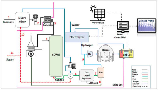
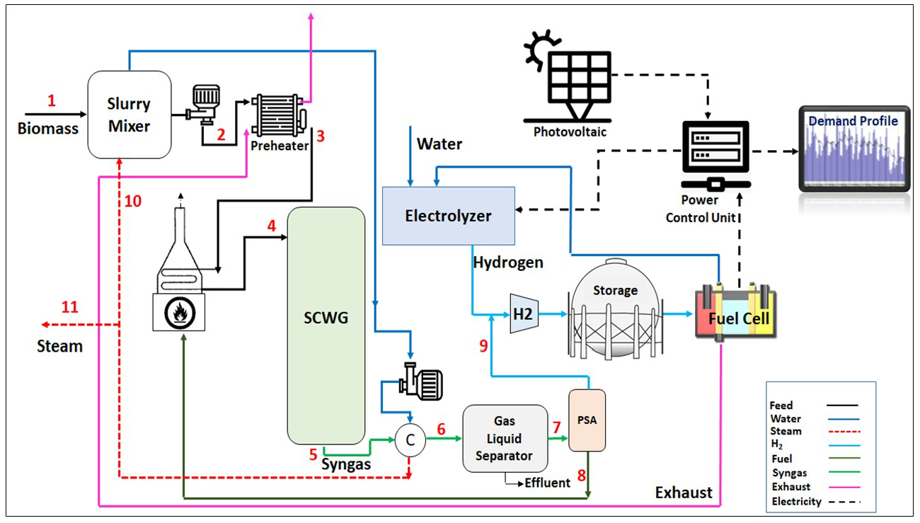
Figure 1 shows the process flow diagram of the proposed HRES. Mixed municipal sewage sludge with a moisture content of up to 60% wt. is pumped and then preheated in a shell and tube heat exchanger which utilizes the hot flue gas from the fuel cell in its shell side. The process stream is then heated in a gas-fired trim heater to reach the gasification temperature of 650 °C before sending it to the SWC gasifier. The gasification reaction is assumed to be thermally neutral. The syngas outflow stream from the gasifier is sent to a water-cooled heat exchanger which uses cold water to lower the temperature of the syngas stream. After cooling, the gas phase of the syngas stream is separated from its liquid phase in a gas–liquid separator and depressurized to 500 psig and then enters a pressure swing adsorption (PSA) which removes its contaminants while recovering about 99.9% of the hydrogen from this stream. The off-gas outflow stream from the PSA is fed to the burners of the gas-fired trim heater. Hydrogen from the PSA unit is subsequently mixed with the hydrogen produced from the electrolyzer which can be stored in a storage tank and fed to the fuel cell. The electric power which is generated by the system can meet external loads through the electrical power output control device.
3. Simulation Model
The assumed basic reaction kinetic of glucose in a SCWG reactor is represented below [20]:
At the supercritical condition, the lower density of water enables SCWG reactor to decompose the biomass feedstock at a faster rate than ideal gases, resulting in the production of hydrogen and methane-rich gases [21,22].
An optimization modeling approach based on the total Gibbs free energy minimization was developed in this paper in order to investigate the equilibrium state of the above reaction and determine the composition of the product gases, which can be explained by using the following Equation [23]:
where:
- : Mole fraction (%),
- : Mole of components,
- : Fugacity of components,
- : Molality based activity coefficient,
- : Standard molar Gibbs energy of components (KJ/mol),
- : Chemical potential under standard pressure,
- : Fugacity under standard pressure,
- : Gasification reaction temperature (K),
- : Gas constant (8.314 J K−1 mol−1),
- : Components in their gaseous and aqueous phases.
Throughout this paper, the required values for and have been obtained from the Aspen HYSYS software. Molality-based activity coefficients for aqueous phases were given in [24]. The fugacity coefficients were estimated by developing the Peng−Robinson Equation of state has as follows [25]:
and
where
Z is the compressibility factor (Z = pv/RT). The subscripts c and ω refer to the critical point and the acentric factor of the substance, respectively. Tc = 373.95 C and Pc = 220.64 bar. The maximum and minimum roots of Equation (4) refer to the gas and liquid phases of the two-phase region. The total Gibbs energy in Equation (2) should be minimized with respect to nij (i = 1, 2, …, ni; j = 1, 2, …, nj) subject to the following constraints:
and the optimum mole numbers of the product gases at the equilibrium state can be found as
The above Equations (2)–(9) were then formulated as a constrained non-linear programming problem, and the CONOPT solver of general algebraic modeling system (GAMS) was used to find the minimum value of the total Gibbs free energy (Equation (2)) as the objective function of the system.
For a fuel cell stack with the following reactions, the output power may be calculated by using Equation (10):
where:
- : Gibbs free energy of the fuel cell reaction (),
- : Molecular weight of hydrogen (g/mole),
- : Mass flow rate of hydrogen (g/s),
- : Fuel cell electric power (W),
- : Maximum efficiently of hydrogen conversion (40–60%).
In a hydrogen-fed fuel cell, water is produced at the rate of one mole for every two electrons. So, the following Equation is adapted to calculate the amount of produced water, (g/s), from the Fuel cell:
F refers to the Faraday constant, which is about 96,485 (C/mole) (C: Coulomb is the equivalent of one ampere-second) is the Fuel cell average voltage (V). is the molecular weight of water (g/mole). To calculate the amount of heat produced by the fuel cell the following Equation may be used:
where, 1.25 V, is the actual voltage of the fuel cell stack. Further details on fuel cell modeling are given in [26,27].
The amount of hydrogen generated from the electrolyzer can be calculated as follows:
where:
- : Amount of hydrogen generated from the electrolyzer (kg),
- : Amount of electricity used in the electrolyzer (kWh),
- : Hydrogen production efficiency 65% to 85% [28], and
- : Calorific value of hydrogen (39.4 kWh/kg)
The electrical output power from the solar panels can be estimated by using the below formula [29,30]:
where:
- : Output power from the solar panel per panel area (W/m2),
- : Temperature coefficient of the panel (1/°C),
- : Rated power under the reference conditions (W/m2),
- : 1000 (W/m2),
- : Reference temperature (25 °C),
- : Solar cell temperature, and
- : Incident solar radiation on the titled surface (W/m2).
The level of hydrogen in the storage tank at time step (t) is estimated based on the amount of hydrogen inflow from the electrolyzer and SCWG at time step (t), and amount of hydrogen outflow to the fuel cell at the time (t):
is the storage efficiency which is assumed to be about 90%. Furthermore, there is upper () and lower limit () for hydrogen level. The upper limit is about 80% of the nominal capacity of tank and lower limit is considered 5% of the rated capacity.
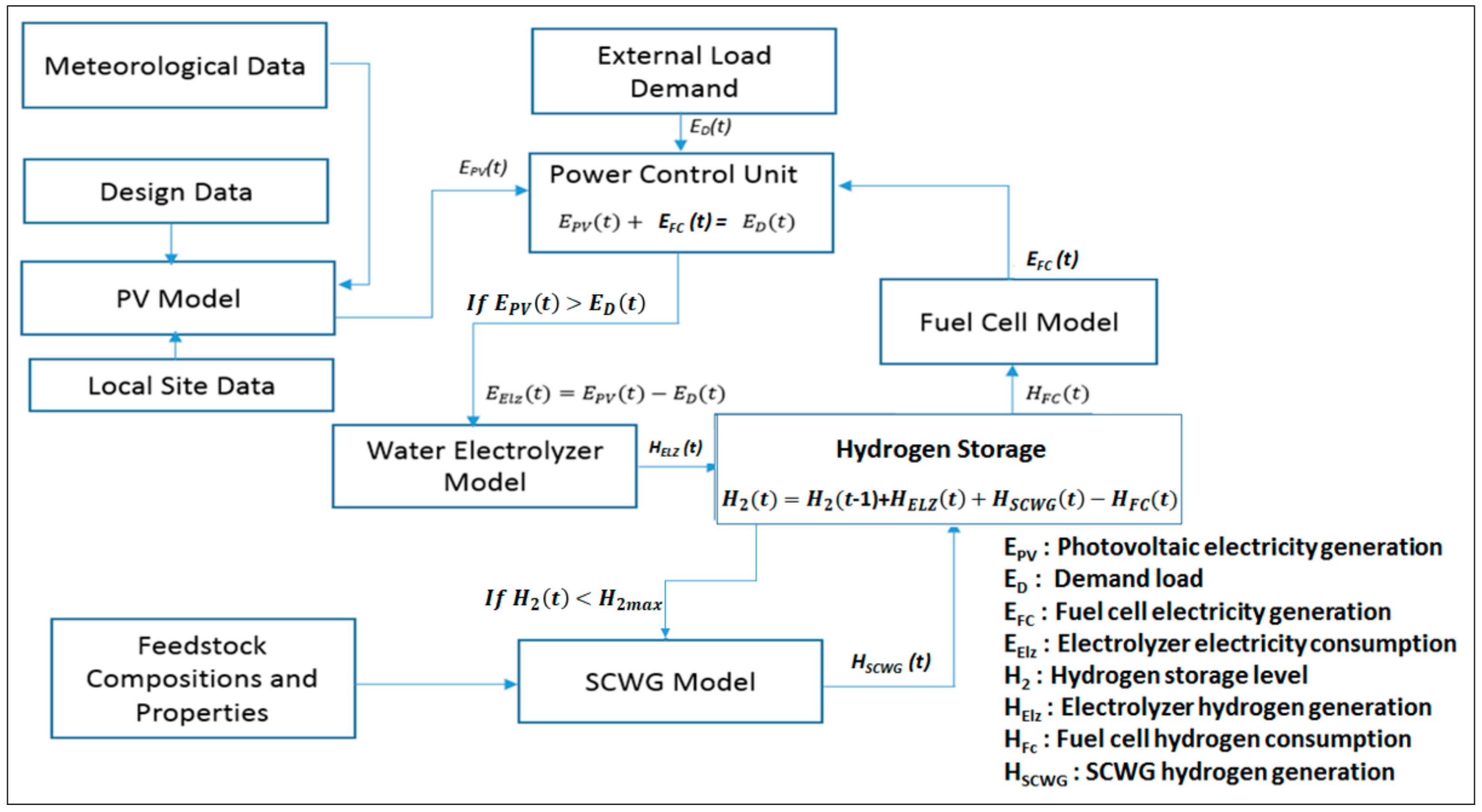
Figure 2 shows the management strategy, which is used to control the amount of power and hydrogen generated by the different components in the proposed HRES.
In this approach, the renewable energy sources (biomass and solar) plus the energy stored in the hydrogen storage are used to cover the demand. The fuel cell is switched on as a backup source when solar energy is not sufficient to supply the load. For each hour step, the simulation program compares the required energy demand and the supplied energy, and according to the difference, a decision to operate the water electrolyzer and SCWG or to charge the hydrogen or discharge it will be taken. The following cases will be considered with the illustrated priority while developing the simulation model:
Case I: The solar PV supplies sufficient generated energy. The use of this energy to supply the load has preference over using the Fuel Cell. The extra energy generated by the solar PV is used in the water electrolyzer to generate hydrogen which will be stored in the hydrogen storage.
Case II: The generated energy by solar PV is not sufficient to supply the load (e.g., during night time). The priority here is to use the Fuel cell. If the hydrogen level is lower than the upper limit () in the storage tank, then the decision to operate SCWG to generate additional hydrogen will be taken by the simulation model.
4. Study Area
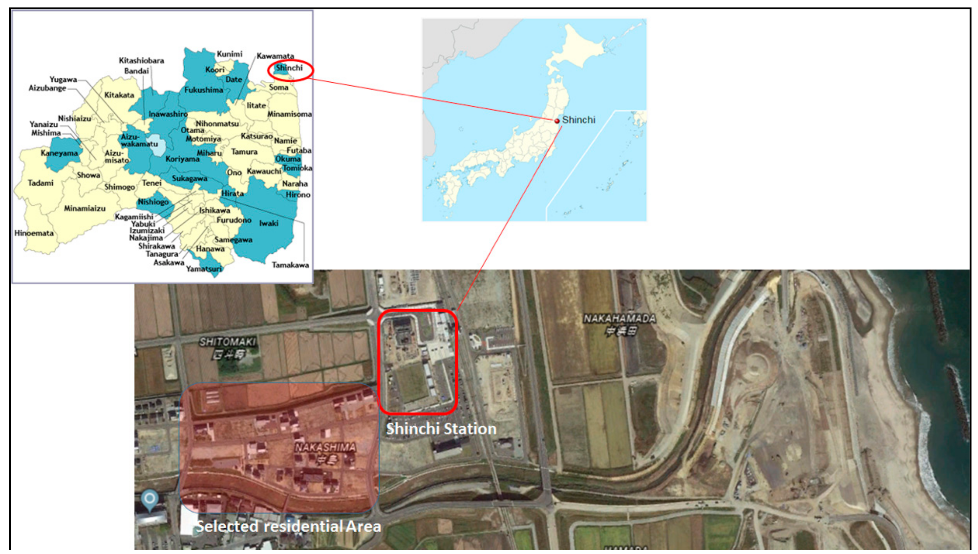
The developed modeling approach was used to estimate the amount of electrical power which can be generated by the proposed HRES and will be needed to satisfy the electrical load requirements in the selected residential area in a subject district around Shinchi station in Fukushima prefecture. This district belongs to the Tohoku region, which the Great East Japan Earthquake occurred there (See Figure 3). The selected area includes 10 detached standard Japanese houses with a daily peak electric power load about 14 kW and total annual electricity consumption of 43,700 kWh.
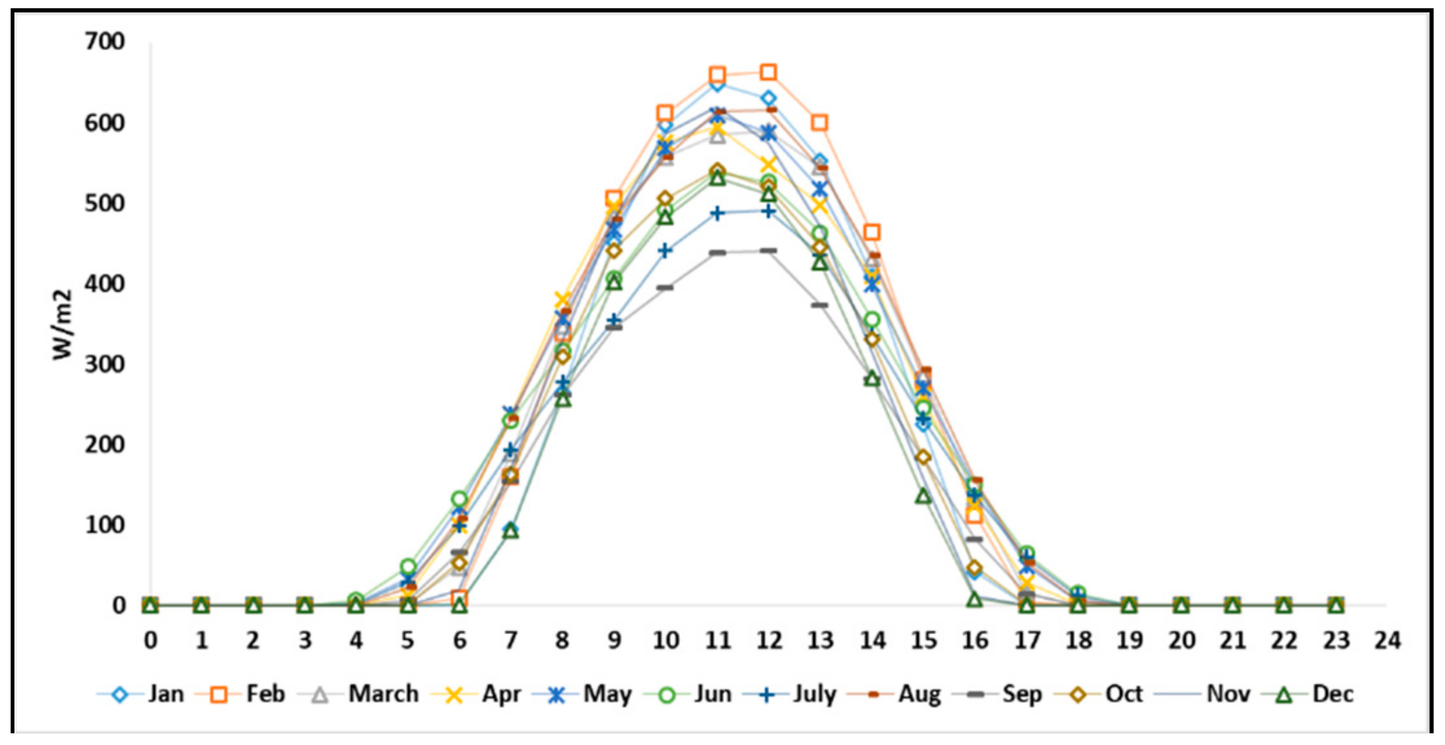
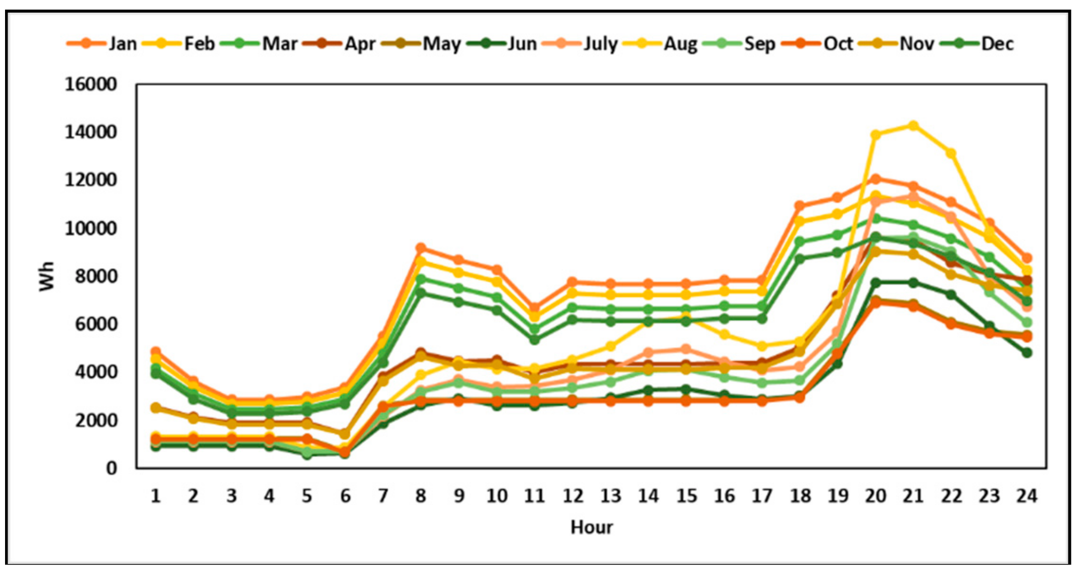
The details of hourly electricity consumption and solar irradiation in the selected residential area are shown in Figure 4. The solar radiation data was collected from the weather station ID: 47595 in Fukushima prefecture [31]. Figure 5 shows the hourly load profile of the typical household in the selected area [32].
5. Results and Discussions
5.1. Heat and Mass Balances
Table 1 shows the assumed chemical composition for the typical kitchen waste as the primary source of wet biomass feed used in the SCWG process.
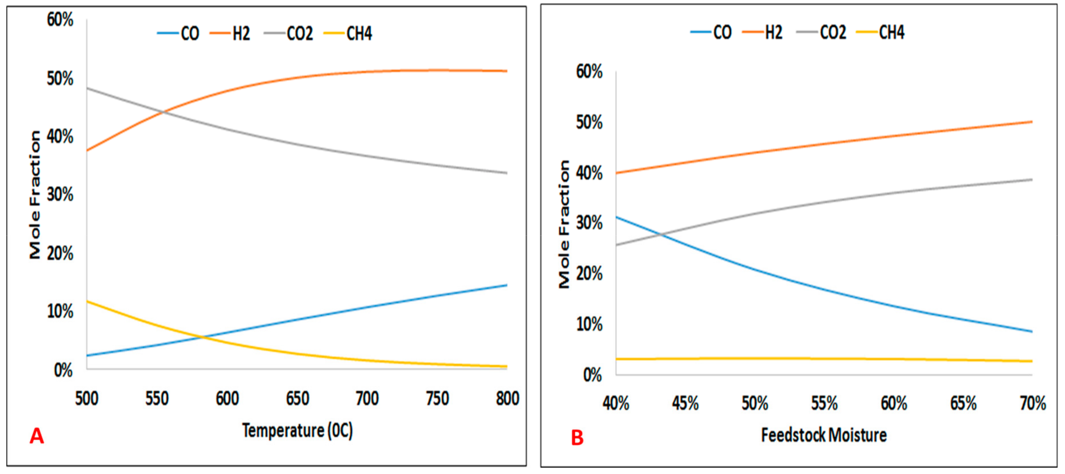
The influence of reaction temperature and biomass feedstock moisture content on SCWG product gas are depicted in Figure 6. It can be observed from this figure that, by increasing the reaction temperature, the concentration of hydrogen and carbon monoxide in the product gas increases. The results also revealed that as the feedstock moisture content increases from about 40 wt.% up to 70 wt.%, carbon dioxide and hydrogen yields increase remarkably.
Comparison between the SCWG model developed here with experimental data is validated in Table 2, in terms of hydrogen yields. The biomass feedstock is glucose for all cases. Different operating temperature and pressure are reported in the experiments. As can be seen the model captures the experimental data well at the operating temperature of 650 °C.
The result of heat and mass balances based on using 1 kg/h of biomass feedstock is presented in Table 3. The amount of required thermal energy for increasing the slurry feed temperature to 650 °C is H4 − H3 = 1104.6 KJ/h which can be provided from burning the off-gas (H8 = 1268.15 kJ/h) in the gas-fired trim heater. The result also indicates that the amount of process steam produced from the cooler (H10 = 725.5 kJ/h) is sufficient to heat the slurry feed (H2 = 517.1 kJ/kg).
5.2. Electricity Generation
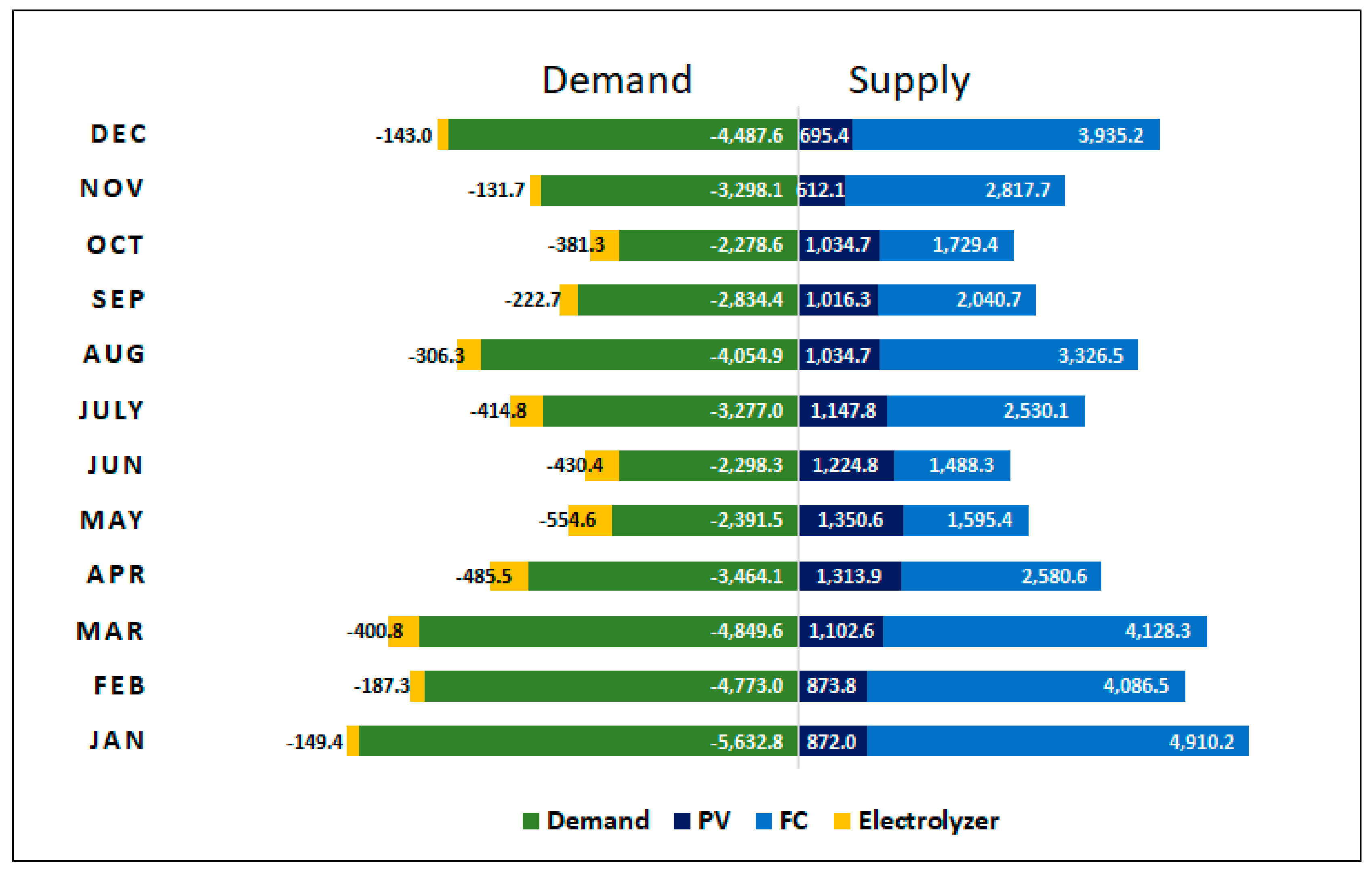
Figure 7 represents the supply-demand balance of electricity in 2018. The annual demand of electricity in the selected residential area is about 43,700 kWh which about 12,279 kWh of this amount can be provided by the solar panel which is less than 40% of the total electricity demand in this area. The input technical data of the solar panel used in the simulation model are listed in Table 4.
5.3. Hydrogen Production and Biomass Consumption
The total annual hydrogen production is estimated at 2850 kg, using the annual wet biomass consumption of 98 tons of possible materials include kitchen waste and organic waste. The total hydrogen generated by the electrolyzer and SCWG was estimated at about 74 kg and 2776 kg by the model, respectively. According to the Ministry of the Environment, Japan, a standard Japanese household generates about 3.2 kg of garbage per day and about 33% of this amount includes wet kitchen waste [38]. Therefore, using additional sources of wet biomass such as sewage sludge from the nearby commercial buildings needs to be considered in this area.
5.4. Cost Analysis
Various scholars have reported cost estimates for the SCWG, which varies in a broad range (see Table 5).
The total capital cost of the proposed HRES was estimated at around USD 311,000 based on the detailed estimation of the size and capacity of each component is reported in Table 6.
The economic analysis of the proposed HRES was based on calculating the levelized cost of electricity (LCOE) of the proposed system, using the following formula [42]:
- : Electricity generation in year t,
- : Discount rate (%). It is assumed to be 0.3% in Japan,
- : Lifetime of the system,
- : Opex in year t,
- : Capex in year t.
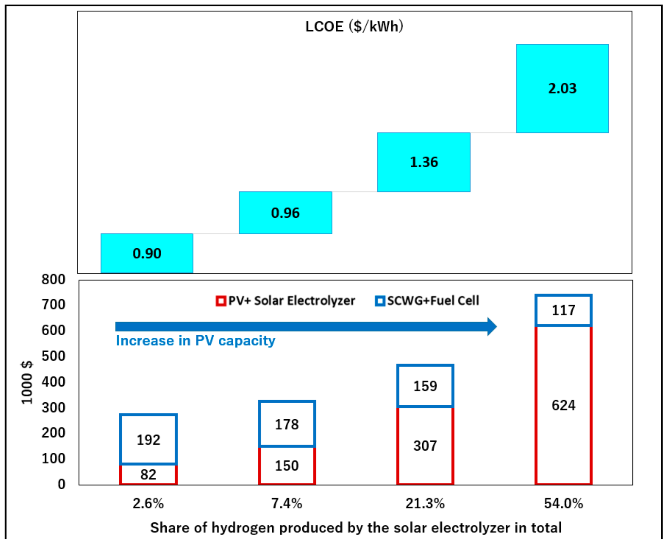
Based on the data reported in Table 4, the levelized cost of energy (LCOE) of the system, including electricity, was estimated at 0.9 $/kWh which is much higher than the average electricity tariff in Japan (0.25 $/kWh). The model was employed to perform sensitivity analyses of the LCOE with respect to the size of solar-powered hydrogen generation system (Solar PV + electrolyzer). The result of the sensitivity analysis shows that the substitution of biomass hydrogen with solar hydrogen can significantly influence the LCOE of the system. As can be seen in Figure 8, by increasing the amount of hydrogen produced by the electrolyzer, the total cost of the system increases. Therefore, the reduction of the cost of the solar hydrogen system turns out to be by far the most important cost driver.
However, If the use of excess thermal energy for in-plant purposes is included, the LCOE of the HRES will be about 0.38 $/kWh. The amounts of extra thermal energy available from the HRES are given in Table 7.
5.5. Water Supply
Consider a cell voltage of 0.7 V which corresponds to an efficiency of 45%, the total amount of produced water from the fuel cell in the proposed HRES is about 15.1 ton per year which more than the amount of water requirement in the electrolyzer. The extra produced water can be used as the makeup water in the sludge mixer.
5.6. CO2 Emission Reduction
The following formula was used to estimate the reduction in CO2 emission from using the proposed HRES in the selected residential area:
where, is the annual CO2 emission reduction by using the proposed HRES (t); is the annual surplus heat quantity (MJ); is the annual electricity generation from the system (kWh). is the CO2 emission factor of liquefied natural gas (LNG) which is supplied from the Soma LNG terminal via Soma-Iwanuma Gas Pipeline to the Shinchi-machi region (kgCO2e/KgLNG). is the CO2 emission factor of the grid electricity generated by proposed HRES in Shinchi-machi (kgCO2e/KWh) and is the calorific heat of LNG (MJ/kg).
Given the standard values for for and , the expected CO2 emission reduction from using the proposed HRES to provide electricity for 10 detached houses in the selected residential area is estimated at about 21 tons per year (see Table 8).
6. Conclusions
The hybridization of various renewable energy sources can allow for smooth, stable, and reliable output to power grids to improve the safety, reliability, and stability of dispatched power, which is more efficient and cheaper than investing in dedicated energy storage options. The most important advantage of the proposed HRES is to make the optimum use of power technologies to tackle limitations on fuel availability, emissions, and economics.
In this study, to promote the application of the HRES, a novel system based on the integration of solar water electrolysis and supercritical water gasification of wet biomass feedstock was proposed. The detailed techno-economic analysis of the proposed HRES was carried in order to provide electricity, heat, hydrogen, and water from aqueous sludge, including kitchen waste and organic waste in a selected residential area in Shinchi-machi, Fukushima prefecture, Japan. The result of the cost analysis of the specific case which was addressed in this paper showed that although the capital requirement of the system is much higher than a single renewable technology, when the excess heat revenue of the HRES is taking into account, the LCOE decreases to the level near to average electricity tariff in Japan.
Funding
This research was supported by the Asia-Pacific Network for Global Change Research (Ref. CRRP2017-07SY-Farzaneh) and the Kurata grant of the Hitachi Global Foundation.
Acknowledgments
The author wishes to thank the editor and the reviewers for their contributions on the paper.
Conflicts of Interest
The author declares no conflict of interest.
References
- Elliott, D.C. Catalytic Hydrothermal Gasification of Biomass. Biofuels Bioprod. Biorefin. 2008, 2, 254–265. [Google Scholar] [CrossRef]
- Jessop, P.G.; Ikariya, T.; Noyori, R. Homogeneous Catalysis in Supercritical Fluids. Chem. Rev. 1999, 99, 475–494. [Google Scholar] [CrossRef] [PubMed]
- Modell, M. Reforming of Glucose and Wood at Critical Conditions of Water. Mech. Eng. 1977, 99, 108. [Google Scholar]
- Savage, P.E. A Perspective on Catalysis in Sub- and Supercritical Water. J. Supercrit. Fluid. 2009, 47, 407–414. [Google Scholar] [CrossRef]
- Reddy, S.N.; Nanda, S.; Dalai, A.K.; Kozinski, J.A. Supercritical water gasification of biomass for hydrogen production. Int. J. Hydrogen Energy 2014, 39, 6912–6926. [Google Scholar] [CrossRef]
- Demirbas, M.F.; Balat, M.; Balat, H. Biowastes-to-Biofuels. Energy Conversat. Manag. 2011, 52, 1815–1828. [Google Scholar] [CrossRef]
- Xu, D.; Wang, S.; Hu, X.; Chen, C.; Zhang, Q.; Gong, Y. Catalytic Gasification of Glycine and Glycerol in Supercritical Water. Int. J. Hydrogen Energy 2009, 34, 5357–5364. [Google Scholar] [CrossRef]
- Yan, B.; Wu, J.; Xie, C.; He, F.; Wei, C. Supercritical Water Gasification with Ni/ZrO2 Catalyst for Hydrogen Production from Model Wastewater of Polyethylene Glycol. J. Supercrit. Fluids 2009, 50, 155–161. [Google Scholar] [CrossRef]
- Huang, J.; Lian, X.; Wang, L.; Zhu, C.; Jin, H.; Wan, R. Hydrogen production from glucose by supercritical water gasification with Ni/Zr(Ce,Y)O2-d catalysts. Int. J. Hydrogen Energy 2017, 42, 4613–4625. [Google Scholar] [CrossRef]
- Duan, P.; Savage, P.E. Upgrading of Crude Algal Bio-Oil in Supercritical Water. Bioresour. Technol. 2011, 102, 1899–1906. [Google Scholar] [CrossRef]
- Xu, X.; Antal, M.J. Gasification of sewage sludge and other biomass for hydrogen production in supercritical water. Environ. Prog. 1998, 17, 215–220. [Google Scholar] [CrossRef]
- Casademonta, P.; Cardozo-Filho, L.; Meurer, E.; Sánchez-Oneto, J.; Portela, J.R. Gasification of olive oil mill waste by supercritical water in a continuous reactor. J. Supercrit. Fluids 2018, 142, 10–21. [Google Scholar] [CrossRef]
- Waldner, M.H. Catalytic Hydrothermal Gasification of Biomass for the Production of Synthetic Natural Gas. Ph.D. Thesis, Eidgenössische Technische Hochschule/Paul Scherrer Institute, Zürich, Switzerland, 2007. [Google Scholar]
- Nakamura, A.; Kiyonaga, E.; Yamamura, Y.; Shimizu, Y.; Minowa, T.; Noda, Y.; Matsumura, Y. Gasification of catalyst-suspended chicken manure in supercritical water. J. Chem. Eng. Jpn. 2008, 41, 433–440. [Google Scholar] [CrossRef]
- Yong, T.L.K.; Matsumura, Y. Catalytic gasification of poultry manure and eucalyptus wood mixture in supercritical water. Ind. Eng. Chem. Res. 2012, 51, 5685–5690. [Google Scholar] [CrossRef]
- Mahmood, T.; Elliott, A.A. Review of Secondary Sludge Reduction Technologies for the Pulp and Paper Industry. Water Res. 2006, 40, 2093–2112. [Google Scholar] [CrossRef]
- Wan, W.; Klas, E.; Weihong, Y. Model investigation of condensation behaviors of alkalis during syngas treatment of pressurized biomass gasification. Chem. Eng. Process. Process Intensif. 2018, 129, 28–36. [Google Scholar] [CrossRef]
- Toonssen, R.; Sollai, S.; Aravind, P.V.; Woudstra, N.; Verkooijen, A.H.M. Alternative system designs of biomass gasification SOFC/GT hybrid systems. Int. J. Hydrogen Energy 2011, 36, 10414–10425. [Google Scholar] [CrossRef]
- Farzaneh, H. Techno-economic study of an innovative PV-hydrogen-biomass system for off-grid power supply. In Proceedings of the 5th IET International Conference on Clean Energy and Technology (CEAT2018), Kuala Lumpur, Malaysia, 5–6 September 2018. [Google Scholar]
- Antal, M.J.; Klass, D.L. Energy from Biomass and Wastes; Inst. of Gas Technology: Chicago, IL, USA, 1978. [Google Scholar]
- Krammer, P.; Vogel, H. Hydrolysis of esters in subcritical and supercritical water. J. Supercrit. Fluids 2000, 16, 189–206. [Google Scholar] [CrossRef]
- Kruse, A.; Dinjus, E. Hot compressed water as reaction medium and reactant. J. Supercrit. Fluids 2007, 39, 362–380. [Google Scholar] [CrossRef]
- Yakaboylu, O.; Harinck, J.; Smit, K.G.; Wiebren, J. Supercritical Water Gasification of Biomass: A Thermodynamic Model for the Prediction of Product Compounds at Equilibrium State. Energy Fuels 2014, 28, 2506–2522. [Google Scholar] [CrossRef]
- Helgeson, H.C.; Kirkham, D.H.; Flowers, G.C. Theoretical prediction of the thermodynamic behaviour of aqueous electrolytes at high pressures and temperatures: IV. Calculation of activity coefficients, and apparent molal and standard and relative partial molal properties to 600 °C and 5 kb. Am. J. Sci. 1981, 281, 1249–1516. [Google Scholar] [CrossRef]
- Peng, D.Y.; Robinson, D.B. A New Two-Constant Equation of State. Ind. Eng. Chem. Fundam. 1976, 15, 59–64. [Google Scholar] [CrossRef]
- Zhao, P.; Wang, J.; Gao, L.; Dai, Y. Parametric analysis of a hybrid power system using organic Rankine cycle to recover waste heat from proton exchange membrane fuel cell. Int. J. Hydrogen Energy 2012, 37, 3382–3391. [Google Scholar] [CrossRef]
- Ahmadi, P.; Dincer, I.; Rosen, M.A. Transient thermal performance assessment of a hybrid solar-fuel cell system in Toronto, Canada. Int. J. Hydrogen Energy 2015, 40, 7846–7854. [Google Scholar] [CrossRef]
- Dufo-Lopes, D.; Bernal-Agustin, J.L. Multi-objective design of PV– wind– diesel– hydrogen– battery systems. Renew. Energy 2008, 33, 2559–2572. [Google Scholar] [CrossRef]
- Farzaneh, H. Energy Systems Modeling Principles and Applications; Springer: Singapore, 2019. [Google Scholar]
- El-Hefnawi, S.H. Photovoltaic diesel-generator hybrid power system sizing. Renew. Energy 1998, 13, 33–40. [Google Scholar]
- Japan Meteorological Agency (JMA). Available online: https://www.data.jma.go.jp/obd/stats/etrn/view/monthly_s3_en.php?block_no=47595&view=11 (accessed on 20 April 2019).
- METI Ministry of Economy, Trade and Industry, Energy Use Rationalization Promotion Based in 2015. Available online: https://www.meti.go.jp/meti_lib/report/2016fy/000233.pdf (accessed on 1 May 2019).
- Antal, M.J.; Allen, S.G.; Schulman, D.; Xu, X.; Divilio, R.J. Biomass Gasification in Supercritical Water. Ind. Eng. Chem. Res. 2000, 39, 4040–4053. [Google Scholar] [CrossRef]
- Kruse, A.J.; Abeln, E.; Dinjus, M.; Kluth, G.; Petrich, M.; Schacht, H.; Sadri, H. Schmieder: Gasification of Biomass and Model Compounds in Hot Compressed Water. In Proceedings of the International Meeting of the GVC-Fachausschu “Hochdruckverfahrenstechnik”, Karlsruhe, Germany, 3–5 March 1999. [Google Scholar]
- Holgate, H.R.; Meyer, J.C. Tester: Glucose Hydrolysis and Oxidation in Supercritical Water. AIChE J. 1995, 41, 637–648. [Google Scholar] [CrossRef]
- Yu, D.M.; Aihara, M.J. Antal: Hydrogen Production by Steam Reforming Glucose in Supercritical Water. Energy Fuels 1993, 7, 574–577. [Google Scholar] [CrossRef]
- General Atomics. Hydrogen Production by Supercritical Water Gasification of Biomass. Phase I-Technical and Business Feasibility Study; Technical Progress Report; General Atomics: San Diego, CA, USA, 1997; Available online: https://digital.library.unt.edu/ark:/67531/metadc709867/m2/1/high_res_d/674646.pdf (accessed on 1 May 2019).
- Yokosuka City. Available online: https://www.city.yokosuka.kanagawa.jp/4220/recycle/genryou/01.html (accessed on 20 April 2019).
- Amos, W.A. Assessment of Supercritical Water Gasification, Milestone Report for the US. Department of Energy’s Hydrogen Program; National Renewable Energy Laboratory: Golden, CO, USA, 1999. [Google Scholar]
- Matsumura, Y. Evaluation of supercritical water gasification and biomethanation for wet biomass utilization. Energy Conversat. Manag. 2002, 43, 1301. (In Japanese) [Google Scholar] [CrossRef]
- Chang, P.L.; Hsu, C.W.; Hsiung, C.M.; Lin, C.Y. Constructing an innovative Bio-Hydrogen Integrated Renewable Energy System. Int. J. Hydrogen Energy 2013, 38, 15660–15669. [Google Scholar] [CrossRef]
- Fraunhofer Instttute for Solar Energy Systems is Levelized Cost of Electricity Renewable Energy Technologies. 2018. Available online: https://www.ise.fraunhofer.de/content/dam/ise/en/documents/publications/studies/EN2018_Fraunhofer-ISE_LCOE_Renewable_Energy_Technologies.pdf (accessed on 1 May 2019).
Figure 1.
The proposed hybrid renewable energy system (HRES) (adopted from [19]). SCWG: supercritical water gasification.
Figure 1.
The proposed hybrid renewable energy system (HRES) (adopted from [19]). SCWG: supercritical water gasification.

Figure 2.
Schematic of the HRES simulation model [29].
Figure 2.
Schematic of the HRES simulation model [29].

Figure 3.
The selected case study in this research.

Figure 4.
Solar irradiation in Fukushima prefecture [31].
Figure 4.
Solar irradiation in Fukushima prefecture [31].

Figure 5.
Hourly typical load profile for 10 detached Japanese standard houses in Fukushima prefecture [32].
Figure 5.
Hourly typical load profile for 10 detached Japanese standard houses in Fukushima prefecture [32].

Figure 6.
Influence of the reaction temp and the feedstock moisture content on SCWG gas production composition. (A) Temperature effect; (B) Moisture effect.
Figure 6.
Influence of the reaction temp and the feedstock moisture content on SCWG gas production composition. (A) Temperature effect; (B) Moisture effect.

Figure 7.
Monthly electricity generation/consumption in the proposed HRES in 2018 (kWh).

Figure 8.
Sensitivity analysis of the levelized cost of electricity (LCOE).


Table 1.
Biomass feedstock composition used in this study
| Component | Mass Fraction |
|---|---|
| C | 50.3% |
| H | 6.17% |
| O | 37.4% |
| N | 0.69% |
Table 2.
Comparison between the SCWG model and various experiments.
| Process Conditions | Hydrogen Yield * (%) | ||
|---|---|---|---|
| Temp (°C) | P (bar) | ||
| This study | 650 | 230 | 50.1 |
| Antal [33] | 745 | 280 | 46.0 |
| Kruse [34] | 600 | 250 | 57.2 |
| Holgate [35] | 600 | 246 | 61.3 |
| Yu [36] | 600 | 345 | 61.6 |
| GA [37] | 650 | 230 | 50.0 |
* Mole fraction of Hydrogen in the product gas.
Table 3.
Heat and mass balance for main streams in the proposed HRES.
| Stream No. | 1 | 2 | 3 | 4 | 5 | 6 | 7 | 8 | 9 | 10 | 11 |
|---|---|---|---|---|---|---|---|---|---|---|---|
| T (°C) | 25 | 200 | 370 | 650 | 650 | 40 | 40 | 25 | 25 | 330 | 330 |
| P (psi) | 15 | 3450 | 3400 | 3400 | 3400 | 3400 | 1950 | 20 | 20 | 70 | 70 |
| M (kg/h) | 1.000 | 1.000 | 1.000 | 1.000 | 1.000 | 1.000 | 0.518 | 0.494 | 0.024 | 0.232 | 0.512 |
| Solid (kg/h) | 0.400 | 0.400 | 0.400 | 0.400 | 0.000 | 0.000 | 0.000 | 0.000 | 0.000 | 0.000 | 0.000 |
| H2O (kg/h) | 0.600 | 0.600 | 0.600 | 0.600 | 0.482 | 0.482 | 0.000 | 0.000 | 0.000 | 0.232 | 0.510 |
| H2 (kg/h) | 0.000 | 0.000 | 0.000 | 0.000 | 0.025 | 0.025 | 0.025 | 0.001 | 0.024 | 0.000 | 0.000 |
| CO (kg/h) | 0.000 | 0.000 | 0.000 | 0.000 | 0.060 | 0.060 | 0.060 | 0.060 | 0.000 | 0.000 | 0.000 |
| CO2 (kg/h) | 0.000 | 0.000 | 0.000 | 0.000 | 0.423 | 0.423 | 0.423 | 0.423 | 0.000 | 0.000 | 0.000 |
| CH4 (kg/h) | 0.000 | 0.000 | 0.000 | 0.000 | 0.011 | 0.011 | 0.011 | 0.011 | 0.000 | 0.000 | 0.000 |
| H (kJ/h) | 0.000 | 517.1 | 1083.6 | 2188.2 | 2441.6 | 113.2 | 29.2 | 1268.15 * | 0.000 | 725.5 | 1602.9 |
* Including the net calorific value of mixed gaseous components.
Table 4.
Technical characteristics of the solar cell (Panasonic: VBHN240SJ25).
| /Item | Value |
|---|---|
| Open circuit voltage (Voc) [V] | 52.4 |
| Short circuit current (Isc) [A] | 5.86 |
| Temp. coefficient of Voc [V/°C] | −0.133 |
| Number of cells | 72 |
| Area (sqm) | 1.26 |
Table 5.
Reported costs for SCWG.
| System | Feedstock (t/d) | Cost (M$) | Reference |
|---|---|---|---|
| SCWG-plant (recycle reactor) + Purified H2 | 9 | 6.5 | [39] |
| SCWG-plant (recycle reactor) + Purified H2 | 90 | 31 | [39] |
| SCWG-plant (recycle reactor) + Purified H2 | 180 | 26 | [39] |
| SCWG-plant + Purified H2 | 180 | 30 | [39] |
| SCWG-plant + rich gas | 5 | 2.1 | [40] |
Table 6.
Cost analysis of the proposed HRES.
| Capacity | Unit Cost ($/Unit) | Opex 1 ($/yr.) | LT (yr.) | Capex 2 ($) | Replace Year | |
|---|---|---|---|---|---|---|
| Solar Cell | 14 (kW) | 4300 | 100.0 | 25 | 60,200 | 20 |
| Fuel Cell | 14 (kW) | 5000 | 150 | 10 | 70,000 | 5 |
| Water Electrolyzer | 11 (kW) | 2000 | 100 | 10 | 22,000 | 15 |
| Hydrogen Storage | 9 (kg) 3 | 1500 4 | 10 | 25 | 13,500 | 20 |
| SCWG | 270 (kg/day) | 450 5 | 65 | 25 | 121,500 | 20 |
| Invertor and Controller | 20 (kW) | 1200 | 0 | 15 | 24,000 | 15 |
| Sum | 311,200 |
1 Operation Cost. 2 Capital Cost. 3 Based on the storage efficiency of 90%. 4 Including both the storage tank and compression unit (~50 bars) [41]. 5 Including a PSA unit for the hydrogen purification.
Table 7.
Extra thermal energy available from the proposed HRES (GJ/y).
| Total | Used | Excess | |
|---|---|---|---|
| Process steam | 207.8 | 50.7 | 157.1 |
| Off-gas | 124.3 | 108.3 | 16.0 |
| Flue gas from the fuel cell | 89.2 | 55.5 | 33.7 |
| Total surplus thermal energy | 421.3 | 214.5 | 206.8 |
Table 8.
Potential reduction in CO2 Emission.
| Potential | Tons Per Year |
|---|---|
| From the renewable electricity | 11.4 |
| From the annul surplus heat | 9.6 |
© 2019 by the author. Licensee MDPI, Basel, Switzerland. This article is an open access article distributed under the terms and conditions of the Creative Commons Attribution (CC BY) license (http://creativecommons.org/licenses/by/4.0/).
Share and Cite
MDPI and ACS Style
Farzaneh, H. Design of a Hybrid Renewable Energy System Based on Supercritical Water Gasification of Biomass for Off-Grid Power Supply in Fukushima. Energies 2019, 12, 2708. https://doi.org/10.3390/en12142708
AMA Style
Farzaneh H. Design of a Hybrid Renewable Energy System Based on Supercritical Water Gasification of Biomass for Off-Grid Power Supply in Fukushima. Energies. 2019; 12(14):2708. https://doi.org/10.3390/en12142708
Chicago/Turabian StyleFarzaneh, Hooman. 2019. "Design of a Hybrid Renewable Energy System Based on Supercritical Water Gasification of Biomass for Off-Grid Power Supply in Fukushima" Energies 12, no. 14: 2708. https://doi.org/10.3390/en12142708
Note that from the first issue of 2016, this journal uses article numbers instead of page numbers. See further details here.