Heat Transfer Characteristics of Heat Exchangers for Waste Heat Recovery from a Billet Casting Process

School of Mechanical Engineering, Yeungnam University, 280 Daehak-ro, Gyeongsan-si, Gyeongbuk 712-749, Korea
*
Author to whom correspondence should be addressed.
Energies 2019, 12(14), 2695; https://doi.org/10.3390/en12142695
Submission received: 21 June 2019
/
Revised: 11 July 2019
/
Accepted: 12 July 2019
/
Published: 15 July 2019
(This article belongs to the Special Issue Heat Exchangers for Waste Heat Recovery)
Abstract
:The application of the thermoelectric generator (TEG) system to various industrial facilities has been explored to reduce greenhouse gas emissions and improve the efficiency of such industrial facilities. In this study, numerical analysis was conducted according to the types and geometry of heat exchangers and manufacture process conditions to recover waste heat from a billet casting process using the TEG system. The total heat absorption increased by up to 10.0% depending on the geometry of the heat exchanger. Under natural convection conditions, the total heat absorption increased by up to 45.5%. As the minimum temperature increased, the effective area increased by five times. When a copper heat exchanger of direct conduction type was used, the difference between the maximum and minimum temperatures was significantly reduced compared to when a stainless steel heat exchanger was used. This confirmed that the copper heat exchanger is more favorable for securing a uniform heat exchanger temperature. A prototype TEG system, including a thermosyphon heat exchanger, was installed and a maximum power of 8.0 W and power density of 740 W/m2 was achieved at a hot side temperature of 130 °C. The results suggest the possibility of recovering waste heat from billet casting processes.
1. Introduction
The global annual energy consumption is 474.1 PJ, of which 52% is discharged as waste heat in exhaust gas and effluents. Particularly in industrial areas, 22% of the total energy is being used annually but only half the amount is being used efficiently [1]. The low efficiency of industrial facilities affects greenhouse gas emissions, which are the main cause of global warming; therefore, the recovery of waste heat is expected to contribute to increasing economic efficiency and decreasing greenhouse gas emissions by improving the efficiency of facilities [2]. For this purpose, waste heat recovery technologies, including heat pumps, boilers, refrigeration cycles, and heat exchangers, have been developed. Among them, the application of the heat pipe and heat exchanger with a thermoelectric generator (TEG) and organic Rankine cycle (ORC) have been studied recently. The ORC system is a waste heat recovery technology that uses an organic refrigerant with low evaporation temperature to produce electric energy through the turbine. Peris et al. [3] installed an ORC system in a ceramic furnace and produced 21.8 kW of power with a maximum efficiency of 12.8% at 287 °C heat source temperature using exhaust gases. Ramirez et al. [4] installed an ORC system on a steel mill and obtained a 21.7% efficiency at a heat source of 529.6 °C. However, the ORC-based waste heat recovery system includes a heat exchanger, pump, and turbine, which limits its application due to its wide installation area. TEG is an eco-friendly energy conversion device that uses the Seebeck effect, in which current is generated from the temperature difference between high-temperature and low-temperature sections at both ends of two semiconductors. Although its current energy conversion efficiency is only 2–5%, a conversion efficiency of 15% or higher is expected to be attainable through the development of material technologies [5,6]. The application of the TEG system to internal combustion engines for waste heat recovery from high-temperature exhaust gas has already been investigated in the transport field. Wang et al. [7] fabricated a prototype TEG system to recover waste heat from the exhaust gas of hybrid vehicles and predicted potential improvement in fuel efficiency by up to 3.6% through experiments on power generation capacity and energy optimization. Moreover, Eddine et al. [8] performed an experiment using a TEG system for recovering waste heat from ship exhaust gas and predicted that maximum energy conversion efficiencies of 0.9% and 1.3% can be achieved with the use of Bi2Te3 at a maximum operating temperature of 250.0 °C and Si80Ge20 at 300.0 °C, respectively. In the industrial field, large amounts of energy can be generated using waste heat recovery systems even with low efficiency because there are various waste heat generation patterns and the scale of waste heat generation is large. For this reason, some studies have investigated the application of the TEG system for recovering industrial waste heat recently. Ebling et al. [9] installed a TEG system for the cooling process of steel forging products using a copper absorber plate to recover radiative waste heat, and produced 388 W of electric power at a heat source temperature of 1300 °C with an efficiency of 2.6%. Yazawa et al. [10] conducted research on the application of the TEG system to a glass melting furnace to recover waste heat. They analyzed various design parameters under the assumption that the TEG module of a direct conduction type was installed on the wall of the furnace, and predicted that a maximum electric power of 55.6 kW can be produced.
For the recovery of industrial waste heat, the TEG system has been applied to processes with high heat source temperatures (600.0 °C or higher), such as steel and glass manufacturing processes. In the case of non-ferrous metal industries, such as aluminum, brass, and copper; however, the temperature of the heat source at which waste heat is generated is in the mid-range, i.e., 300.0–600.0 °C, and thus the power generated by TEG is significantly reduced. Therefore, for processes with mid-range heat source temperature, the energy conversion efficiency of the TEG module as well as the heat transfer efficiency from the heat source to the TEG module must be considered in order to produce a large amount of energy. In addition, it is necessary to conduct research on the geometry and types of heat exchangers as important design parameters of the TEG system according to the waste heat generation patterns. In particular, for radiative energy, plate-type heat exchangers have been mostly used in the TEG system for heat sources located on horizontal surfaces, such as conveyor belts [9,11]. In actual processes, however, waste heat is generated from more complex geometry and plate-type heat exchangers cannot recover heat efficiently. Thus, some studies have been conducted to recover waste heat using heat pipes. A heat pipe consists of an evaporation unit, an insulation unit, and a condensation unit. The heat exchanger transfers heat through phase change via evaporation and condensation of the internal working fluid. The applicable temperature range of the heat source is wide and the heat transfer efficiency is high. For the application of heat pipes to industrial facilities, various geometries and performance parameters have been investigated through experiments and numerical analysis [12,13,14]. Regarding studies on the use of heat pipes in the TEG system, Huang et al. [15] confirmed a maximum output of 6.25 W in a TEG module using a loop heat pipe, and Wu et al. [16] showed that the use of heat pipes increased the TEG power generation efficiency by up to 50% in a comparative experiment using heat pipes and plates as heat spreaders. Heat pipe pyroelectric system with energy harvesting technology is similar to heat pipe TEG system. However, pyroelectric devices are more suitable where the temperature of the heat source changes over time [17,18]. The TEG system seems to be suitable because the heat source of this study is less temperature change with time.
This study attempted to minimize heat loss in a brass billet cooling process by applying a heat exchanger with the geometry of the area surrounding the billet such that heat could be more efficiently absorbed than plate-type heat exchangers. The TEG system was applied for the first time to the billet cooling process with a cylindrical heat source that generates waste heat of 600.0 °C or less. For the application of the heat exchanger, the difference in heat absorption and surface temperature distribution were analyzed according to the geometry of the heat exchanger and process conditions through numerical analysis. In addition, the reliability of the numerical analysis of the target heat source was verified through experiments. A prototype TEG system with a thermosyphon heat pipe was installed in the billet casting cooling process. Experiments on the output power and measurement of the temperatures of the high-temperature and low-temperature sections of the heat pipe and TEG module were performed.
2. Experimental Setup and Numerical Analysis
2.1. Experimental Setup
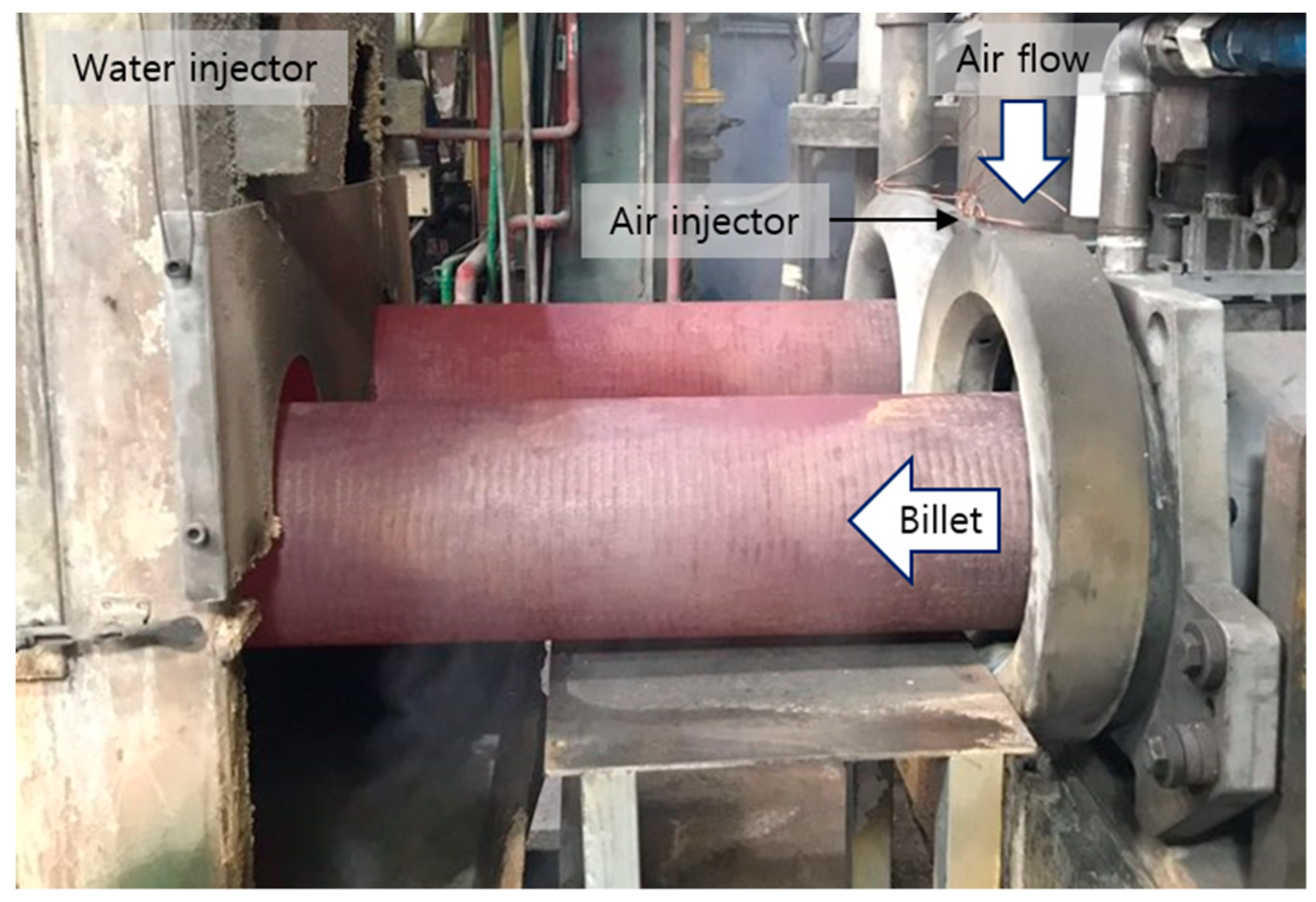
In this study, the brass billet cooling process in Gwangmyeong-si, Korea, was set as the target of the TEG system for waste heat recovery. The side exposed to the ambient after the billet continuous casting process was set as the target position, as shown in Figure 1. The billet diameter was 240 mm and the billet length exposed to the outside was 600 mm. An air injector was installed at the outlet of the casting machine to cool the billet surface, and the billet entered the water injector through an air cooling section. Heat loss from the billet at the waste heat recovery position was caused by natural convection due to the high-temperature surface, forced convection due to the air injector, and radiation around the billet. Regarding the heat exchanger for waste heat recovery from the billet, a non-contact heat exchanger is required because the billet moves after casting. As the flow around the billet is also not constant due to the air injector, the waste heat is recovered through radiative heat exchange.
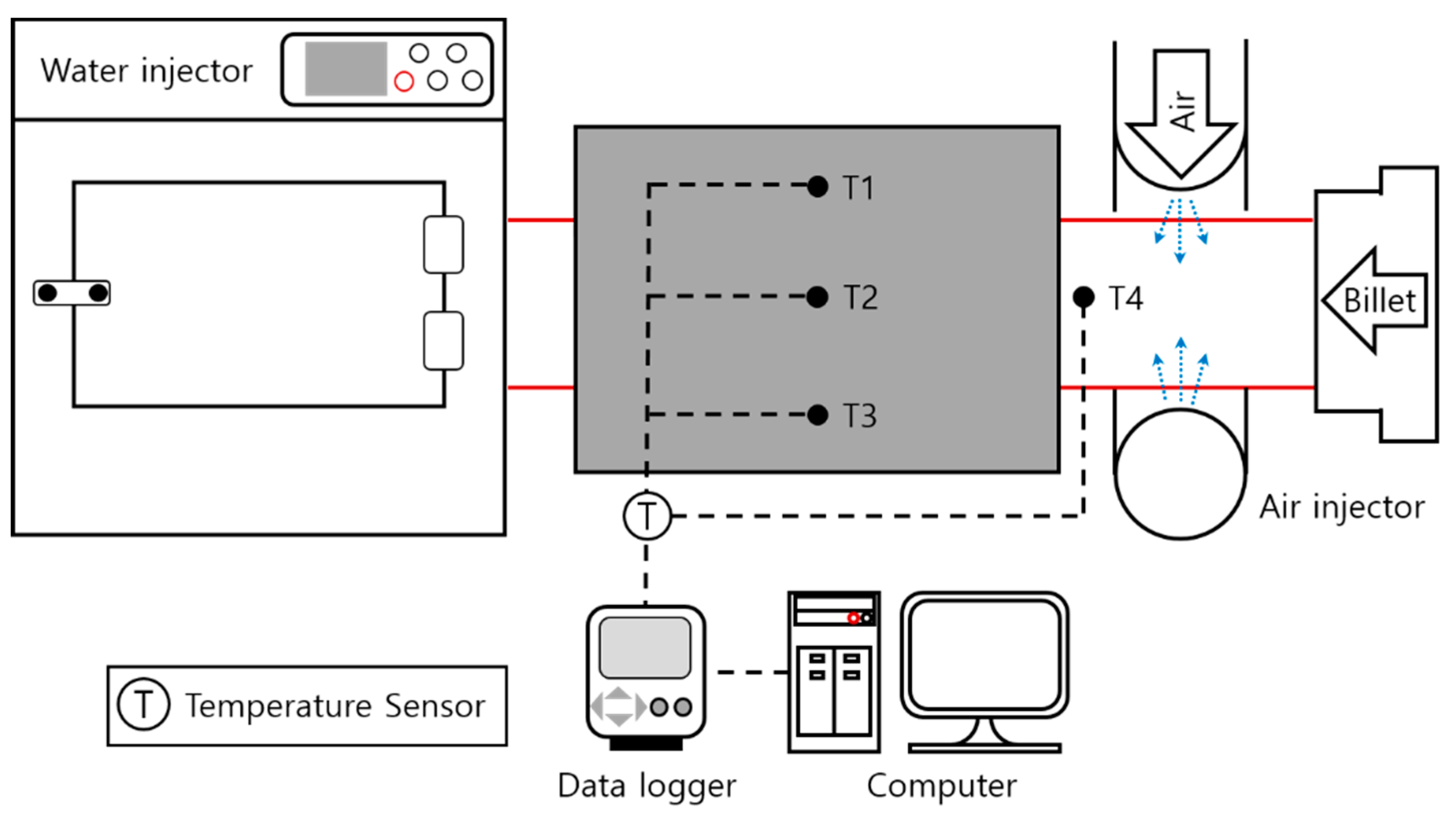
A temperature measurement experiment was performed to verify the analysis. Figure 2 shows the schematic diagram of the experimental apparatus. An air injector was installed at the outlet of the casting machine to inject air towards the billet and a centrifugal fan capable of providing a volumetric flow rate of up to 63 m3/min was connected. A SUS 316 absorber plate was installed at 20 mm from the billet to measure the radiative heat temperature between the water injector and the air injector. The length, height, and thickness of the plate were 500, 290, and 5 mm, respectively. For temperature measurement, three thermocouples were attached to the center of the specimen at 105 mm height intervals. An additional thermocouple was attached to measure the temperature distribution on the billet surface. As the billet was cast and moved, the thermocouples also moved and the surface temperatures of the billet were measured at a distance from the outlet of the casting machine. Table 1 shows the specifications of the experimental apparatus. In the experiment, the temperature of the specimen was judged to reach a steady state when temperature changes in the three thermocouples attached to the absorber plate were 3.0 °C or less considering the errors of the thermocouples and the data logger. The specimen reached a steady state in approximately 30 min. The average temperatures at each position were calculated by collecting temperature data for more than 10 min and they were used as result data.
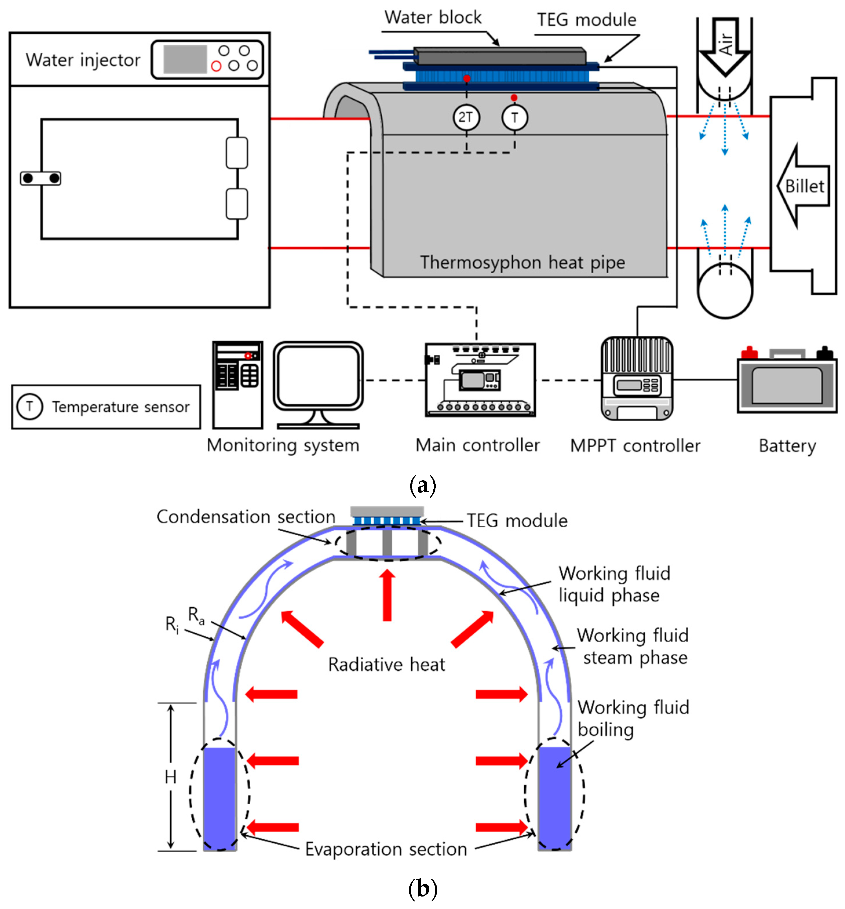
Figure 3a shows the schematic diagram of the radiative waste heat recovery TEG system for the experiment on output power. Radiative waste heat from the billet was recovered using the SUS 316 heat pipe. The working fluid of the heat pipe evaporated on the surface facing the billet and condensed on the top plate with the TEG module. Three K-type thermocouples were attached to measure the temperatures of the heat pipe condensation section as well as the high-temperature and low-temperature sections of the TEG module. The charging controller of the maximum power point tracking (MPPT) type was used to charge the battery with electrical energy generated by the TEG module. The battery charging power from the MPPT controller and the temperatures measured from the heat pipe and TEG module were transferred to the monitoring system through the main controller to enable real-time data collection and verification. Bi2Te3 was used in the installed TEG module. This material affords a maximum conversion efficiency of 3.4% when the maximum operating temperature of the high-temperature section is 300.0 °C and the temperature difference between both ends is 250 °C. Three modules with width, depth, and height of 60, 60, and 3.7 mm, respectively, were used. Figure 3b is a schematic diagram of the heat pipe composed of a single wick. The radius of the heat absorption plate of the wick, Ra, is 130 mm, the radius of the heat insulation plate, Ri, is 160 mm, the height of the wick portion, H, is 160 mm, and the total axial length is 500 mm. The filling ratio of the internal working fluid was set to 30%. In the heat pipe, DOWTHERM-A, a mixture of C12H10 and C12H10O, was used as the working fluid, with the operating temperature ranging from 15.0 to 400.0 °C. Table 2 shows all the specifications of the TEG system.
2.2. Numerical Analysis Model and Boundary Conditions
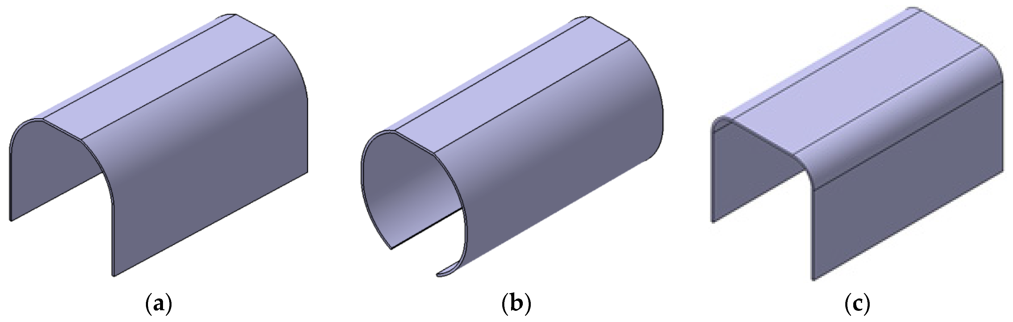
The heat exchanger for waste heat recovery was modeled in three geometrical shapes, as shown in Figure 4. The first model is the n-type shown in Figure 4a. It targeted at heat transfer to the TEG module installed at the top using the heat pipe. Flat plates were applied to the sides such that the fixing jig could be installed at the bottom. The second model is the o-type shown in Figure 4b. It is a model for comparing differences in heat absorption and temperature distribution according to the heat exchanger geometry. The flat plates on the side of the n-type were bent towards the billet such that radiative waste heat could be absorbed effectively. The third model is the d-type shown in Figure 4c. It targeted at heat transfer through direct conduction after the recovery of radiative waste heat. The TEG module can be installed both on the side and at the top, unlike the n-type and o-type. SUS 316 was used for the n-type and o-type considering the mechanical durability of the heat pipe, and they had the same heat exchange area of 0.4 m2. Copper was used for the d-type for effective heat conduction through direct conduction. Its heat exchange area is the same as those of the n-type and o-type. Table 3 shows the specifications of all heat exchanger models.
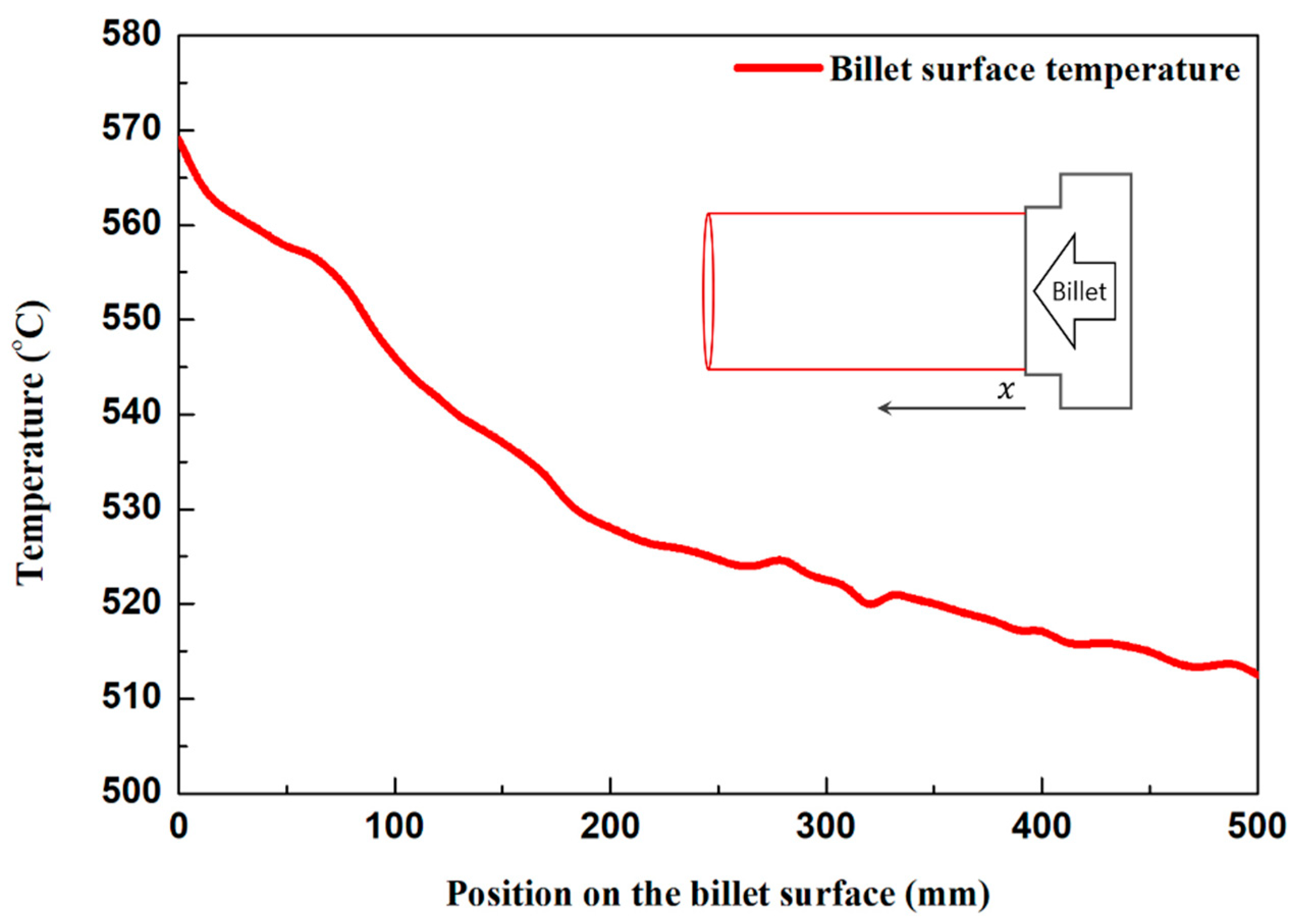
ANSYS Fluent (ver. 19.2), a commercial software program, was used for heat flow analysis in this study. Table 4 shows the analysis method. The analysis was conducted on the domain, including the billet, air injector, and heat exchanger. Air was used as an incompressible ideal gas under steady-state, incompressible flow, and turbulent conditions. Moreover, the convergence of the residual was increased using the coupled algorithm and pseudo transient approach. The realizable k-epsilon model was used to simulate the turbulent flow around the billet and heat exchanger caused by the air injector. The scalable wall function was used to compensate for the grid quality degradation occurring from the narrow space between the billet and heat exchanger. The pressure was set as the body force weighted scheme considering the occurrence of the natural convection effect on the surface of the billet. The radiative heat exchange between the billet and heat exchanger is the main heat exchange method in this analysis and the surface to surface (S2S) model was used as an analytical model. The S2S model calculates radiative heat exchange using the view factor and assumes the heat exchange medium as a gray body and a diffusive surface. The absorption coefficient and the scattering coefficient could be neglected in the model, and the model was suitable for the analysis because there was no permeable medium in the analytical domain of this study [19]. For a somewhat larger scale with geometry similar to that of this study, Mirhosseini et al. [20] conducted 2D numerical analysis on the radiative heat exchange of an arc absorber around a cylindrical cement kiln using an S2S model. Table 5 shows the boundary conditions used for heat flow analysis. Emissivity, a surface property, was set to 0.7 for the brass billet, 0.4 for SUS 316, and 0.5 for copper [21,22,23]. Figure 5 shows the results of measuring the billet surface temperature. Considering the process, the average temperature of 530 °C at the position where the heat exchanger can be installed was set as the surface temperature of the billet. To compare the heat absorption and temperature distribution under forced convection and natural convection conditions, blower flow rates of 0 and 0.18 kg/s were added to each geometrical shape.
3. Results and Discussion
Approximately 15 million grids were used to ensure grid independence of the analytical model. Convergence was determined when the residual value of energy dropped below 10−6 and the remaining residual value dropped below 10−4. The reliability of the analytical model was confirmed through the experiment for analysis verification and the maximum error of 2.4%. Table 6 shows temperatures and errors at each measuring point obtained from the numerical analysis and the experiment.
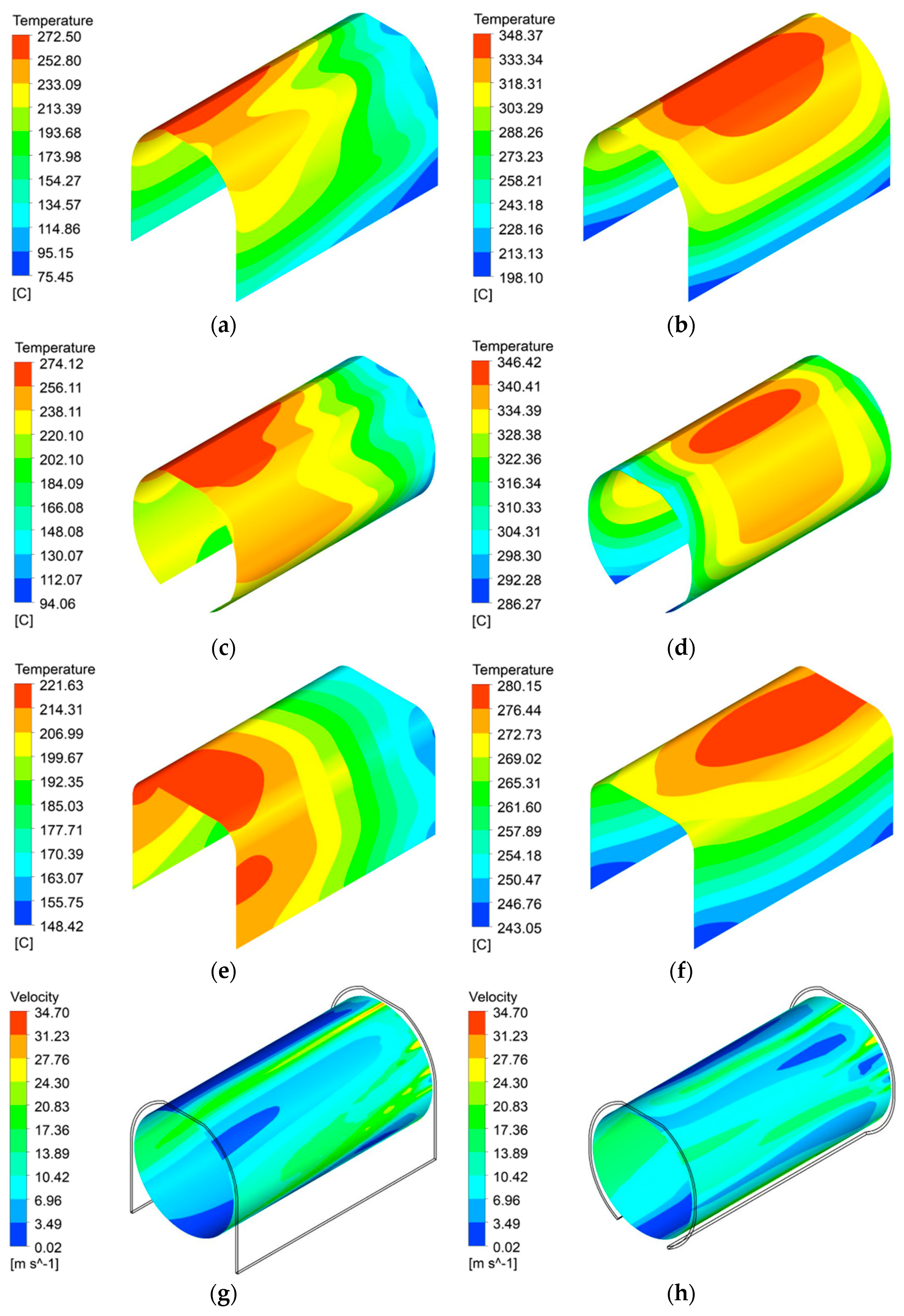
Figure 6 shows the temperature distribution according to the geometry of the SUS 316 heat exchanger. Under forced convection conditions, the high-temperature section on the heat exchanger surface was formed at the front for all geometrical shapes. Figure 6a shows the surface temperature distribution of the n-type under the forced convection condition. The maximum temperature was 272.5 °C, whereas the minimum temperature was 75.5 °C. Figure 6c shows the surface temperature distribution of the o-type under the same condition. The maximum temperature was 274.1 °C, whereas the minimum temperature was 94.1 °C. The difference in the maximum temperature between the n-type and o-type was small (1.6 °C), but the difference in the minimum temperature was relatively large (18.6 °C) with the o-type exhibiting higher minimum temperature. The asymmetric temperature distribution of the symmetric heat exchanger could be predicted because the position of the injection hole on the air injector is not symmetrical. Figure 6b and d show the heat exchanger surface temperature distributions of the n-type and o-type, respectively, under the natural convection condition. The maximum temperature was 348.4 °C for the n-type and 346.4 °C for the o-type, showing an increase of up to 75.9 °C compared to the maximum temperatures obtained under the forced convection condition. This can be attributed to the increase in the temperature of the heat exchanger with the weakening of the effect of forced convection, reducing heat loss on the surface. Moreover, the minimum temperature was 198.1 °C for the n-type and 286.3 °C for the o-type, showing an increase of up to 192.2 °C. The temperature difference between the n-type and o-type was obvious under the natural convection condition. Figure 6e shows the surface temperature distribution of the d-type under the forced convection condition. The maximum temperature was 221.6 °C, whereas the minimum temperature was 148.4 °C. Figure 6f shows the surface temperature distribution of the d-type under the natural convection condition. The maximum and minimum temperatures were 280.2 °C and 243.0 °C, respectively. While the difference between the maximum and minimum temperatures was up to 197 °C for the n-type and o-type, that of the d-type was up to 73.2 °C, which is significantly low. The difference between the maximum and minimum temperatures of the d-type appeared to decrease because of the high thermal conductivity of copper. For the d-type, a uniform temperature distribution is required for the heat exchanger because heat is transferred to the TEG module through direct conduction. The analysis results showed that the use of the copper heat exchanger is appropriate because it exhibits a relatively uniform temperature distribution.
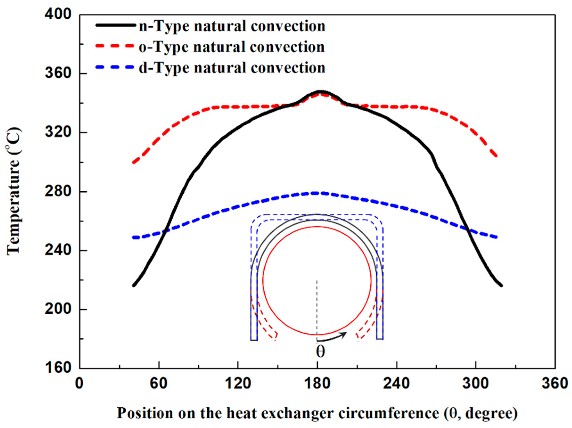
As shown in Figure 6g,h, a convection layer was formed between the billet and the heat exchanger. The high-temperature section was concentrated at the front because the cooling air that entered the rear end of the heat exchanger close to the air injector was slowly heated as it passed between the billet and the heat exchanger. Figure 7 shows the temperature distribution along the heat exchanger circumference. The maximum temperature was not significantly different depending on the geometry, but the temperature significantly increased in the o-type due to the bent sides.
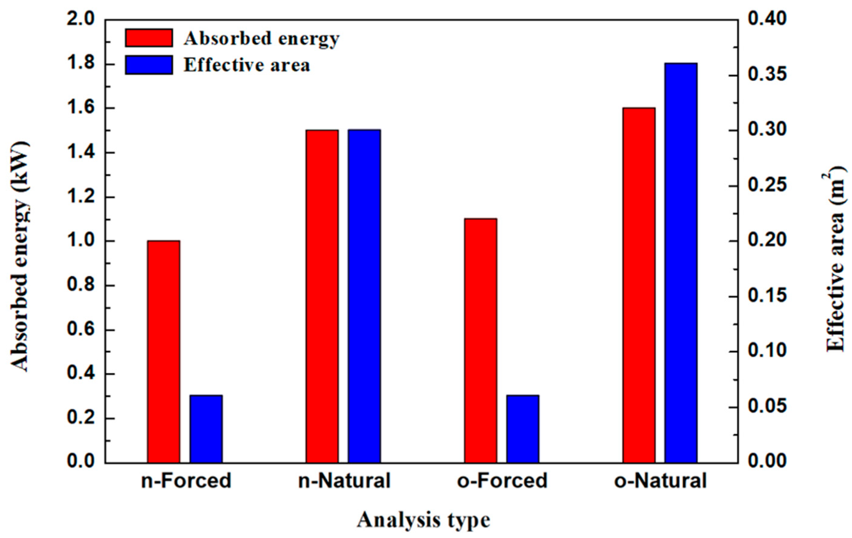
Although stainless steel was selected considering the mechanical durability of the heat pipe, the temperature difference between the high-temperature and low-temperature sections was large due to its low thermal conductivity. To determine the area where the working fluid can evaporate and heat absorbed when heat pipes are used, the effective area and waste heat absorption were analyzed according to the geometrical and flow conditions for the basic design of the heat exchanger. The effective area was defined as the area where the temperature of the heat absorbing section was 250 °C or higher considering that the maximum operating temperature of the high-temperature section of the TEG module was 300 °C. The effective area and waste heat absorption, according to the geometry and flow conditions, are shown in Figure 8. Under the forced convection condition, a total of 1.0 kW waste heat was absorbed by the heat exchanger for the n-type. For the o-type under the same condition, the radiative heat energy absorbed from the billet increased due to the bent sides and 1.1 kW waste heat was absorbed. Under the natural convection condition, the energy loss attributable to convection decreased and thus the n-type and o-type absorbed 1.5 kW and 1.6 kW waste heat, respectively. The effective area did not significantly differ depending on the geometry, and it significantly increased under the natural convection condition. Thus, most of the area exhibited 250 °C or higher for both the n-type and o-type, indicating effective heat transfer. The numerical analysis results confirmed that the geometry contributed to 10% improvement of waste heat absorption but it did not significantly affect the maximum temperature and effective area. Under the natural convection condition, however, waste heat absorption was increased by up to 45.5% and the effective area was increased up to five times.
The TEG system with an n-type prototype thermosyphon was tested under the forced convection condition. Table 7 shows the temperatures and output power of the TEG system in a steady state. In the actual experiment, the temperature of the condensation section of the heat exchanger was 263.3 °C, meeting the proper operating temperature of the TEG module. In the numerical analysis, the temperature of the high-temperature section at the top of the n-type was similar to that at the top of the thermosyphon with an error of 3.5%. The temperature of the high-temperature section of the TEG module was 130 °C, which was also appropriate as it was in the operating temperature range. The three TEG modules provided an output power of 8.0 W when the temperature of the low-temperature section was 49.8 °C and the temperature difference between both ends was 80.2 °C. The temperature drop that occurred at the condensation section of the heat exchanger and the high-temperature section of the TEG module; however, was a major obstacle to the system output. This temperature drop can be attributed to the insufficient waste heat recovery and low thermal conductivity of the TEG system. Regarding the evaporation section, as confirmed by the numerical analysis, the evaporation of the working fluid was not sufficient because the thermosyphon evaporation section could not secure sufficient temperature and heat absorption, thereby, degrading the performance of the heat exchanger itself. As confirmed through the numerical analysis, heat absorption was increased by 50.0% under the natural convection condition. Therefore, if the air injector is removed from the TEG system as a means of securing output and an experiment is performed under the natural convection condition, the output of the TEG system is expected to increase. The heat exchanger output can also be increased by increasing the emissivity of the thermosyphon through surface treatment, such as surface blackening using carbon coating.
4. Conclusions
In this study, the heat absorption and temperature distribution of a TEG system for recovering waste heat from a brass billet casting process were analyzed according to the heat exchanger type, geometry, and process condition using numerical analysis. Heat absorption could be increased by up to 10.0% depending on the geometrical variables, but the maximum temperature did not significantly change. Moreover, when the forced convection condition was changed to the natural convection condition, of which the blower flow rate was 0 kg/s, heat absorption could be increased by up to 45.5%, the maximum temperature was also increased by 75.9 °C, and the effective area increased five times, thereby, exhibiting more effective heat transfer. The heat exchanger of a direct conduction type also met the proper operating temperature of the TEG module and exhibited a uniform temperature distribution, thereby, suggesting its feasibility for practical application. Moreover, the experiment on the output power of the TEG system with the n-type thermosyphon under the forced convection condition confirmed the output power of 8.0 W.
The results of this study confirmed the possibility of recovering waste heat from industrial facilities. The application of the TEG system is expected to improve the efficiency of facilities and contribute to the selection of heat exchangers for the TEG system according to the type of waste heat generated. The system outputted only 8 W during the actual process because the heat transfer between the heat exchanger and TEG module has not been optimized yet. In the future, for the optimal design of heat exchangers and improvement of the output power, various types of heat exchangers and heat exchangers with coated surfaces for improving heat transfer performance will be applied to the TEG system and experiments as well as numerical analysis on power generation performance and economic assessment of its applicability will be conducted.
Author Contributions
J.OK. performed the experimental/numerical analysis and drafted the manuscript. S.C.K. organized the overall evaluation and reviewed the manuscript.
Funding
This work was conducted as a part of the Energy Technology Development project sponsored by the Ministry of Trade, Industry and Energy (No. 20172010000760).
Acknowledgments
The support received from the Livingcare company is greatly appreciated.
Conflicts of Interest
The authors declare no conflict of interest.
Nomenclatures
| H | Height |
| R | Radius |
| Thickness (mm) | |
| Emissivity | |
| Subscripts | |
| a | Absorption plate |
| b | Billet |
| cp | Copper |
| i | Insulation plate |
| ss | Stainless steel |
References
- Forman, C.; Muritala, I.K.; Pardemann, R.; Meyer, B. Estimating the global waste heat potential. Renew. Sustain. Energy Rev. 2016, 57, 1568–1579. [Google Scholar] [CrossRef]
- Firth, A.; Zhang, B.; Yang, A. Quantification of global waste heat and its environmental effects. Appl. Energy 2019, 235, 1314–1334. [Google Scholar] [CrossRef]
- Peris, B.; Navarro-Esbri, J.; Moles, F.; Mota-Babiloni, A. Experimental study of an ORC (organic Rankine cycle) for low grade waste heat recovery in a ceramic industry. Energy 2015, 85, 534–542. [Google Scholar] [CrossRef]
- Ramirez, M.; Epelde, M.; Gomez de Arteche, M.; Panizza, A.; Hammerschmid, A.; Baresi, M.; Monti, N. Performance evaluation of an ORC unit integrated to a waste heat recovery system in a steel mill. Energy Procedia 2017, 129, 535–542. [Google Scholar] [CrossRef] [Green Version]
- Huang, F.; Zheng, J.; Baleynaud, J.M.; Lu, J. Heat recovery potentials and technologies in industrial zones. J. Energy Inst. 2017, 90, 951–961. [Google Scholar] [CrossRef]
- Jouhara, H.; Khordehgah, N.; Almahmoud, S.; Delpech, B.; Chauhan, A.; Tassou, S.A. Waste heat recovery technologies and applications. Therm. Sci. Eng. Prog. 2018, 6, 268–289. [Google Scholar] [CrossRef]
- Wang, R.; Yu, W.; Meng, X. Performance investigation and energy optimization of a thermoelectric generator for a mild hybrid vehicle. Energy 2018, 162, 1016–1028. [Google Scholar] [CrossRef]
- Eddine, A.N.; Chalet, D.; Faure, X.; Aixala, L.; Chesse, P. Optimization and characterization of a thermoelectric generator prototype for marine engine application. Energy 2018, 143, 682–695. [Google Scholar] [CrossRef]
- Ebling, D.G.; Krumm, A.; Pfeiffelmann, B.; Gottschald, J.; Bruchmann, J.; Benim, A.C.; Adam, M.; Labs, R.; Herbertz, R.R.; Stunz, A. Development of a system for thermoelectric heat recovery from stationary indusrial processes. J. Electron. Mater. 2016, 45, 3433–3439. [Google Scholar] [CrossRef]
- Yazawa, K.; Shakouri, A.; Hendricks, T.J. Thermoelectric heat recovery from glass melt processes. Energy 2017, 118, 1035–1043. [Google Scholar] [CrossRef]
- Kuroki, T.; Kabeya, K.; Makino, K.; Kajihara, T.; Kaibe, H.; Hachiuma, H.; Matsuno, H.; Fujibayashi, A. Thermoelectric generation using waste heat in steel works. J. Electron. Mater. 2014, 43, 2405–2410. [Google Scholar] [CrossRef]
- Shabgard, H.; Allen, M.J.; Sharifi, N.; Benn, S.P.; Faghri, A.; Bergman, T.L. Heat pipe heat exchangers and heat sinks: Opportunities, challenges, applications, analysis, and state of the art. Int. J. Heat Mass Transf. 2015, 89, 138–158. [Google Scholar] [CrossRef]
- Jouhara, H.; Almahmoud, S.; Chauhan, A.; Delpech, B.; Bianchi, G.; Tassou, S.A.; Llera, R.; Lago, F.; Arribas, J.J. Experimental and theoretical investigation of a flat heat pipe heat exchanger for waste heat recovery in the steel industry. Energy 2017, 141, 1928–1939. [Google Scholar] [CrossRef]
- Delpech, B.; Axcell, B.; Jouhara, H. Experimental investigation of a radiative heat pipe for waste heat recovery in a ceramics kiln. Energy 2019, 170, 636–651. [Google Scholar] [CrossRef]
- Huang, B.J.; Hsu, P.C.; Tsai, R.J.; Hussain, M.M. A thermoelectric generator using loop heat pipe and design match for maximum-power generation. Appl. Therm. Eng. 2015, 91, 1082–1091. [Google Scholar] [CrossRef] [Green Version]
- Wu, S.; Ding, Y.; Zhang, C.; Xu, D. Improving the performance of a thermoelectric power system using a flat-plate heat pipe. Chin. J. Chem. Eng. 2019, 27, 44–53. [Google Scholar] [CrossRef]
- Nguyen, H.; Navid, A.; Pilon, L. Pyroelectric energy converter using co-polymer P(VDF-TrFE) and Olsen cycle for waste heat energy harvesting. Appl. Therm. Eng. 2010, 30, 2127–2137. [Google Scholar] [CrossRef]
- Poprawski, W.; Gnutek, Z.; Radojewski, J.; Poprawski, R. Pyroelectric and dielectric energy conversion – A new view of the old problem. Appl. Therm. Eng. 2015, 90, 858–868. [Google Scholar] [CrossRef]
- FLUENT Inc. Fluent 6.3 User’s Guide; FLUENT Inc.: Havover, NH, USA, 2006. [Google Scholar]
- Mirhosseini, M.; Rezaniakolaei, A.; Rosendahl, L. Numerical study on heat transfer to an arc absorber designed for a waste heat recovery system around a cement kiln. Energies 2018, 11, 671. [Google Scholar] [CrossRef]
- Shi, D.; Liu, Q.; Zhu, Z.; Sun, J.; Wang, B. Experimental study of the relationships between the spectral emissivity of brass and the temperature in the oxidizing environment. Infrared Phys. Technol. 2014, 64, 119–124. [Google Scholar] [CrossRef]
- Nam, H.Y.; Lee, G.Y.; Kim, J.M.; Choi, S.K.; Park, J.H.; Choi, I.G. Experimental Study on the Emissivity of Stainless Steel. In Proceedings of the Korean Nuclear Society Spring Meeting, Cheju, Korea, 24–25 May 2001; Available online: https://inis.iaea.org/search/searchsinglerecord.aspx?recordsFor=SingleRecord&RN=33040336 (accessed on 20 May 2019).
- Incropera, F.P.; Dewitt, D.P. Foundations of Heat Transfer, 6th ed.; John Wiley & Sons: New York, NY, USA, 2013. [Google Scholar]
Figure 1.
Brass billet continuous casting process.

Figure 2.
Schematic diagram of the experimental apparatus for analysis verification.

Figure 3.
Schematic diagrams of the thermoelectric generator (TEG) system and heat pipe (a) TEG system; (b) heat pipe.
Figure 3.
Schematic diagrams of the thermoelectric generator (TEG) system and heat pipe (a) TEG system; (b) heat pipe.

Figure 4.
Geometry of the waste heat exchanger absorber plate. (a) n-Type; (b) o-Type; (c) d-Type.

Figure 5.
Temperature distribution on the billet surface.

Figure 6.
Temperature distribution with different heat exchanger shapes and air flow and velocity distribution between the billet and the heat exchanger (a) n-Type forced convection; (b) n-Type natural convection; (c) o-Type forced convection; (d) o-Type natural convection; (e) d-Type forced convection; (f) d-Type natural convection; (g) n-Type forced convection; (h) o-Type forced convection.

Figure 7.
Surface temperature distribution along the heat exchanger circumference.

Figure 8.
Heat absorption with different heat exchanger shapes and air flow.


Table 1.
Specifications of the experimental apparatus for analysis verification.
| Sensor and Measure Instrument | Specification |
|---|---|
| Thermocouple (Omega, K-type) | 0.75% (−270.0–1372.0 °C) 3 points absorber plate, 1 point billet |
| Data logger (Kimo) | 4 channels (−200.0–1372.0 °C) |
| Absorber plate (SUS 316) | 400 (W) × 290 (H) × 5 (t) |
| Blower (Kigeonsa) | Centrifugal fan Max volume flow rate: 63 m3/min |
Table 2.
Specifications of the TEG system.
| Component | Specification |
|---|---|
| TEG modules | Bi2Te3, 3.4% at dT: 250 °C 60 (W) × 60 (L) × 3.7 (H) 3 ea |
| Heat pipe (SUS 316) | Type: Thermosyphon Working fluid: DOWTHERM-A Operating Temperature: (15.0–400.0 °C) |
| MPPT controller | Max input power: 260 W-12 V, 520 W-24 V |
| Main controller (Espressif) | Apply 10 temperature sensors |
Table 3.
Specifications of heat exchanger model.
| Type | n-Type | o-Type | d-Type |
|---|---|---|---|
| Material | SUS 316 | Copper | |
| Thermal conductivity (W/m·K) | 14.8 | 65.0 | |
| Length (mm) | 500.0 | ||
| Thickness (mm) | 5.0 | ||
| Heat transfer area (m2) | 0.4 | ||
| Heat exchanger type | Heat pipe | Direct conduction | |
Table 4.
Analysis method.
| Component | Model and Boundary Conditions |
|---|---|
| State | Steady state, Incompressible ideal gas |
| Algorithm | Coupled, Pseudo transient |
| Pressure | Body force weighted |
| Turbulence | Realizable k-epsilon |
| Wall function | Scalable wall function |
| Radiation | S2S |
Table 5.
Analysis of boundary conditions.
| Component | Boundary Condition |
|---|---|
| Emissivity | : 0.7, : 0.4, : 0.5 |
| Billet temperature (°C) | 530.0 |
| Mass flow rate (kg/s) | Forced convection: 0.2 Natural convection: 0 |
Table 6.
Temperature difference between experimental and numerical analysis.
| Measuring Point | Experimental Result (°C) | Numerical Result (°C) | Error (%) |
|---|---|---|---|
| T1 | 135.6 | 138.9 | 2.4 |
| T2 | 169.4 | 171.3 | 1.1 |
| T3 | 151.9 | 154.2 | 1.5 |
Table 7.
Temperatures and output power of the TEG system.
| Type | Condenser Temperature (°C) | TEG Hot Side Temperature (°C) | TEG Cold Side Temperature (°C) | Output (W) |
|---|---|---|---|---|
| Experimental | 263.3 | 130 | 49.8 | 8.0 |
© 2019 by the authors. Licensee MDPI, Basel, Switzerland. This article is an open access article distributed under the terms and conditions of the Creative Commons Attribution (CC BY) license (http://creativecommons.org/licenses/by/4.0/).
Share and Cite
MDPI and ACS Style
Kang, J.O.; Kim, S.C. Heat Transfer Characteristics of Heat Exchangers for Waste Heat Recovery from a Billet Casting Process. Energies 2019, 12, 2695. https://doi.org/10.3390/en12142695
AMA Style
Kang JO, Kim SC. Heat Transfer Characteristics of Heat Exchangers for Waste Heat Recovery from a Billet Casting Process. Energies. 2019; 12(14):2695. https://doi.org/10.3390/en12142695
Chicago/Turabian StyleKang, Ju O, and Sung Chul Kim. 2019. "Heat Transfer Characteristics of Heat Exchangers for Waste Heat Recovery from a Billet Casting Process" Energies 12, no. 14: 2695. https://doi.org/10.3390/en12142695
Note that from the first issue of 2016, this journal uses article numbers instead of page numbers. See further details here.