Article

Harmonic Stability Analysis for Multi-Parallel Inverter-Based Grid-Connected Renewable Power System Using Global Admittance †

1
School of Electrical Engineering, Southeast University, Nanjing 210096, China
2
Jiangsu Provincial Key Laboratory of Smart Grid Technology and Equipment, Nanjing 210096, China
3
State Grid Jiangsu Electric Power Co., Ltd. Research Institute, Nanjing 210096, China
*
Author to whom correspondence should be addressed.
This paper is an extended version of our paper published in: W. Cao, D. Fan, K. Liu, J. Zhao, L. Ruan and X. Wu, “Harmonic Stability Assessment based on Global Admittance for Multi-Paralleled Grid-Connected VSIs using Modified Nyquist Criterion,” 2018 International Power Electronics Conference (IPEC-Niigata 2018—ECCE Asia), Niigata, 2018, pp. 3015–3019.
Energies 2019, 12(14), 2687; https://doi.org/10.3390/en12142687
Submission received: 20 June 2019 / Revised: 8 July 2019 / Accepted: 10 July 2019 / Published: 12 July 2019
(This article belongs to the Special Issue Electric Power Systems Research 2019)

Abstract

:
Multi-parallel grid-connected voltage source inverters (VSIs) are widely applied in the fields of renewable energy, energy storage, harmonic suppression, etc. However, these inverters may cause harmonic stability problems due to the interactions among the grid-connected inverters through the grid impedance, which can seriously threaten system stability. The impedance-based stability criterion provides an effective tool for analyzing harmonic instability issues and can be divided into two types, namely, a ratio type and a sum type. Based on the existing studies of the sum-type criterion, this paper further proposes a new sum-type form based on the global admittance from the PCC to assess system stability through frequency-domain analysis. This global admittance-based stability criterion can be used not only to analyze system stability, but also to reveal the influence of each VSI unit on system stability with a lower computational burden and provide guidance for resonance suppression, especially in the case of a large number of grid-connected inverters and asymmetric inverter parameters. Finally, a MATLAB/Simulink model and 400 kVA/400 V experimental platform consisting of six grid-connected VSIs were established, and the corresponding results are presented to verify the effectiveness of the proposed method.

Graphical Abstract

1. Introduction

Currently, multi-parallel grid-connected inverters with the features of effective controllability and high efficiency are widely applied in modern power systems, such as renewable energy generation, electric railway, energy storage, and harmonic suppression systems [1,2], as shown in Figure 1. However, the large-scale use of inverters will inject high-order harmonics into the power grid and may result in series and parallel resonance [3,4]. The interactions among individual inverters and with passive components, especially capacitors, may cause power system instability [5,6,7,8,9,10,11]. Consequently, it is necessary to anticipate system stability before connecting inverters to the power grid, especially under weak grid conditions. The existing stability analysis methods can be divided into two types: Nonlinear and linear methods. The nonlinear methods [12,13] involve intensive computations and are not suitable for large-scale grid-connected systems. In contrast, the linear methods require fewer computations and can be used to intuitively assess system stability. Eigenvalue-based and impedance-based methods are two common linear analysis techniques used to assess power system stability [14].
The eigenvalue-based approach is implemented in the time domain [15,16,17]. To utilize the eigenvalue-based approach, a state-space model of the whole system, including inverters and loads, should be established. Then, the state-space model is linearized around a fixed operation point. Next, the eigenvalues of the linearized model can be determined. The system is stable if and only if all the eigenvalues have a negative real part [18]. The eigenvalue-based method is a global stability analysis method that is not limited by the selection of interface points. This approach is suitable for well-defined systems with parameters and operations that do not vary frequently, such as traditional power systems. Individual loads are not important in such systems because of their small capacities. However, the corresponding principles have not been established for grid-connected systems in which the number of grid-connected inverters changes frequently and loads play an important role. When loads or grid-connected inverters are added or removed, the establishment of the state-space model should be repeated, which makes the analysis process inefficient.
The impedance-based approach is a frequency-domain analysis technique [19,20,21,22,23,24,25,26]. This method was originally presented in [19] and was used to study the interactions between DC-DC converters and their filters. A grid-connected inverter is modeled as a current source in parallel with an output impedance, and the loads are modeled as input impedances. The system stability at the point of common coupling (PCC) can be assessed by determining whether the ratio of the load input impedance to the inverter output impedance (defined as the minor loop gain (MLG)) satisfies the Nyquist stability criterion [21,22,23]. Compared to the eigenvalue-based approach, the formulation of the system matrix can be avoided in this method. Changing the number of inverters or the operation mode of loads only influences one impedance element, which consequently has a minimal effect on the system model. Apart from the ratio-type impedance-based stability criterion, a sum-type stability criterion for hybrid energy storage systems is proposed to assess the harmonic instability in a simpler way because the right half plane zeros in the impedance of the subsystem are not required [27]. Therefore, the system stability can be analyzed in one step only instead of two steps using the traditional ratio-type criterion. However, the advantages of the sum-type criterion include not only the simplification of the stability determination procedure but also the identification of the characteristics of the particular system.
To further study the application of the sum-type criterion in a multi-parallel grid-connected system, this paper proposes a global admittance-based stability criterion. The global admittance from the PCC is defined as the summation of all the admittances, including the grid admittance, other passive admittances, and all the output admittances of the inverters. The stability can be assessed based on a frequency-domain analysis of global admittance. Compared to the state-space model and eigenvalue-based approach, adding or removing inverters has a minimal effect on the system model. Thus, the approach is applicable to grid-connected systems. This method is a global stability analysis technique, and there is no need to analyze the stability of each inverter, which reduces the computational burden. Additionally, the effects of individual components on the system stability can be determined. This criterion indicates that the sufficient and necessary condition for grid-connected system stability is that the global admittance has a positive real part at the resonance frequency, thereby providing stability-oriented design guidelines.
This paper is organized as follows. The parallel system is modeled and analyzed in Section 2. And in this section, the current-loop admittance model is given. Section 3 introduces the traditional impedance-based stability criterion for the single grid-connected inverter system and multi-parallel grid-connected inverter system. In Section 4, the proposed global admittance-based stability criterion is introduced. Especially, the system stability analysis when inverters with different parameters are connected to the grid is discussed in this section. The simulation and experimental results are provided to validate the theoretical approach in Section 5. Finally, Section 6 summarizes the work.

2. System Modeling

In this section, the parallel system is modeled and analyzed. On this basis, the current-loop admittance model and equivalent model of the multi-parallel grid-connected voltage source inverter (VSI) system are given.

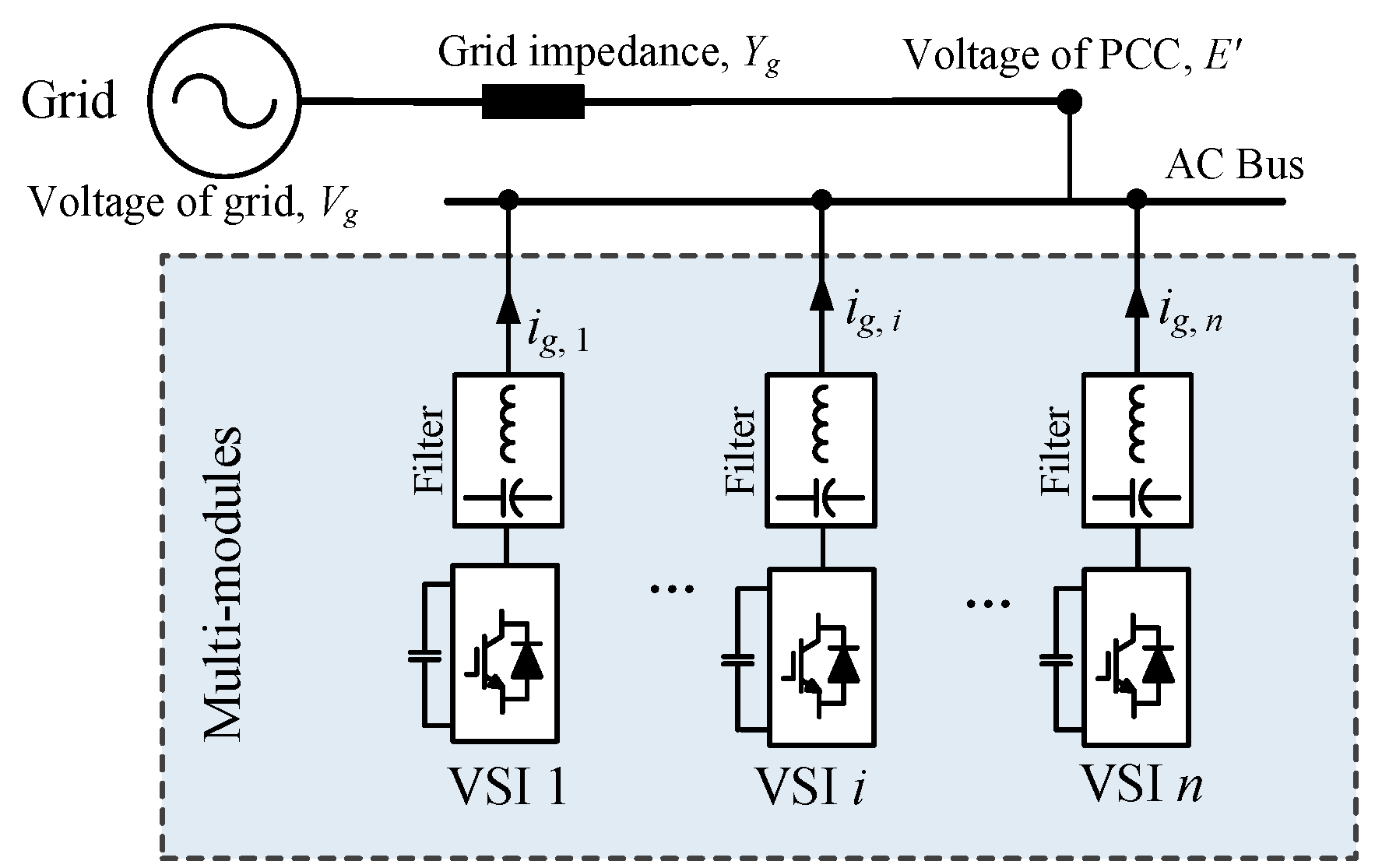
2.1. System Description

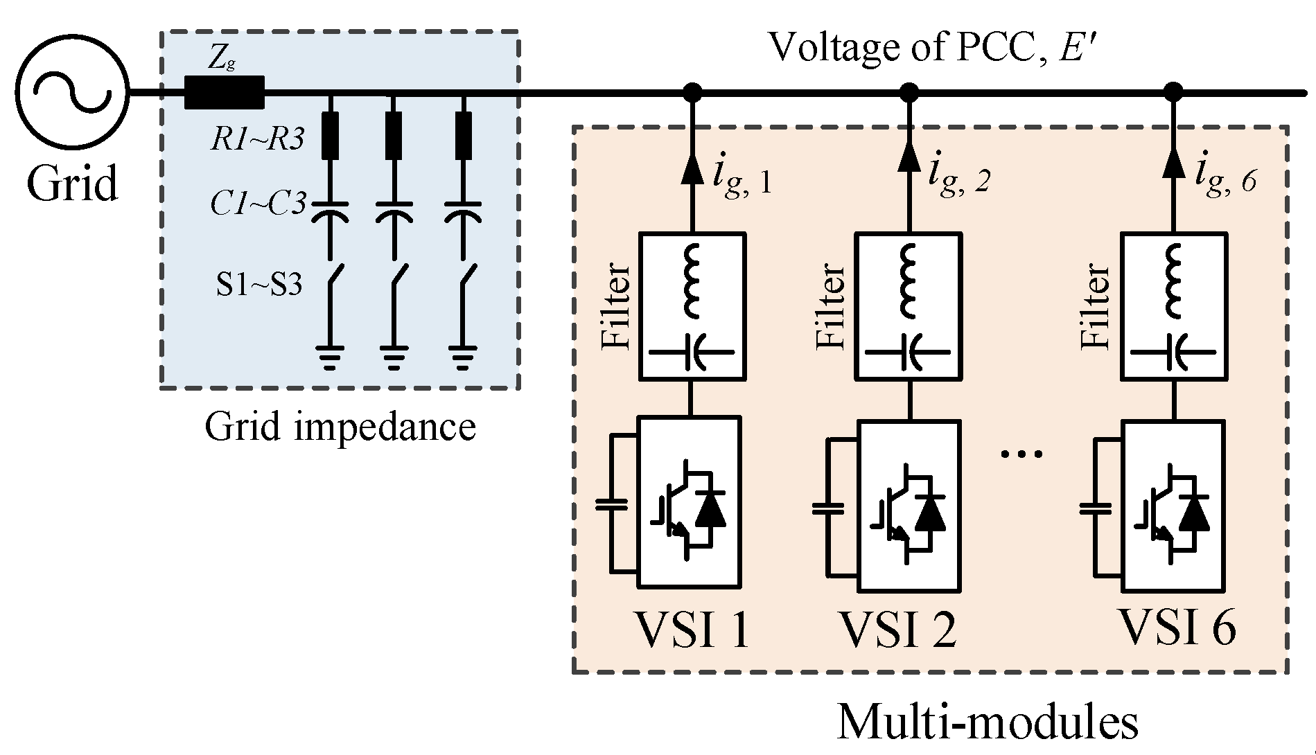
The multi-parallel grid-connected VSI system is shown in Figure 2. Multiple inverters are connected to the power grid via a common AC bus. The VSIs operate as current sources that inject real power into the power grid. In such a grid-connected VSI system, due to the non-negligible grid impedance, the control loops of inverters interact with each other, which will result in a resonance phenomenon. The interactions between the inverters and capacitors of filters will also lead to oscillations.

2.2. Admittance Modeling of a Single-Inverter System

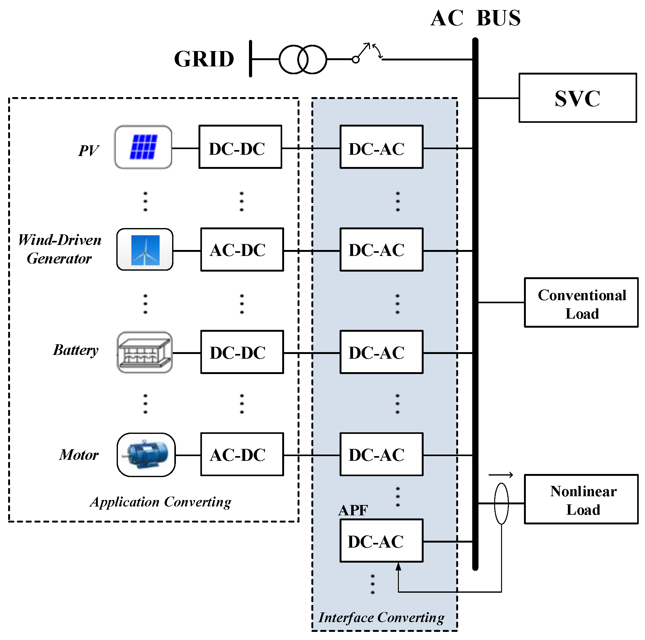
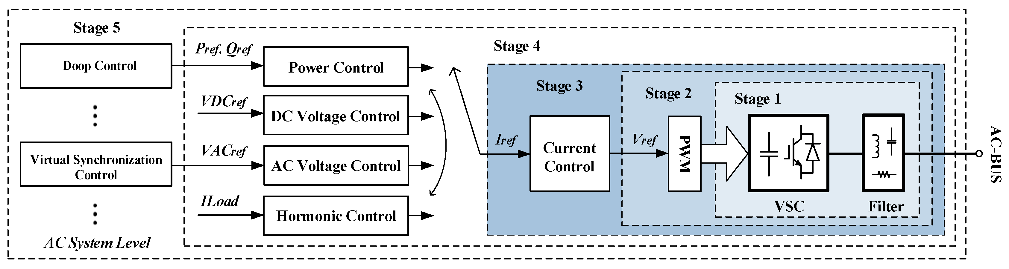
There are three types of grid-connection modes: Current-controlled source mode, voltage-controlled source mode, and harmonic compensation mode. The multi-inverter parallel systems in various fields are typically composed of a control target and bottom control, as shown in 
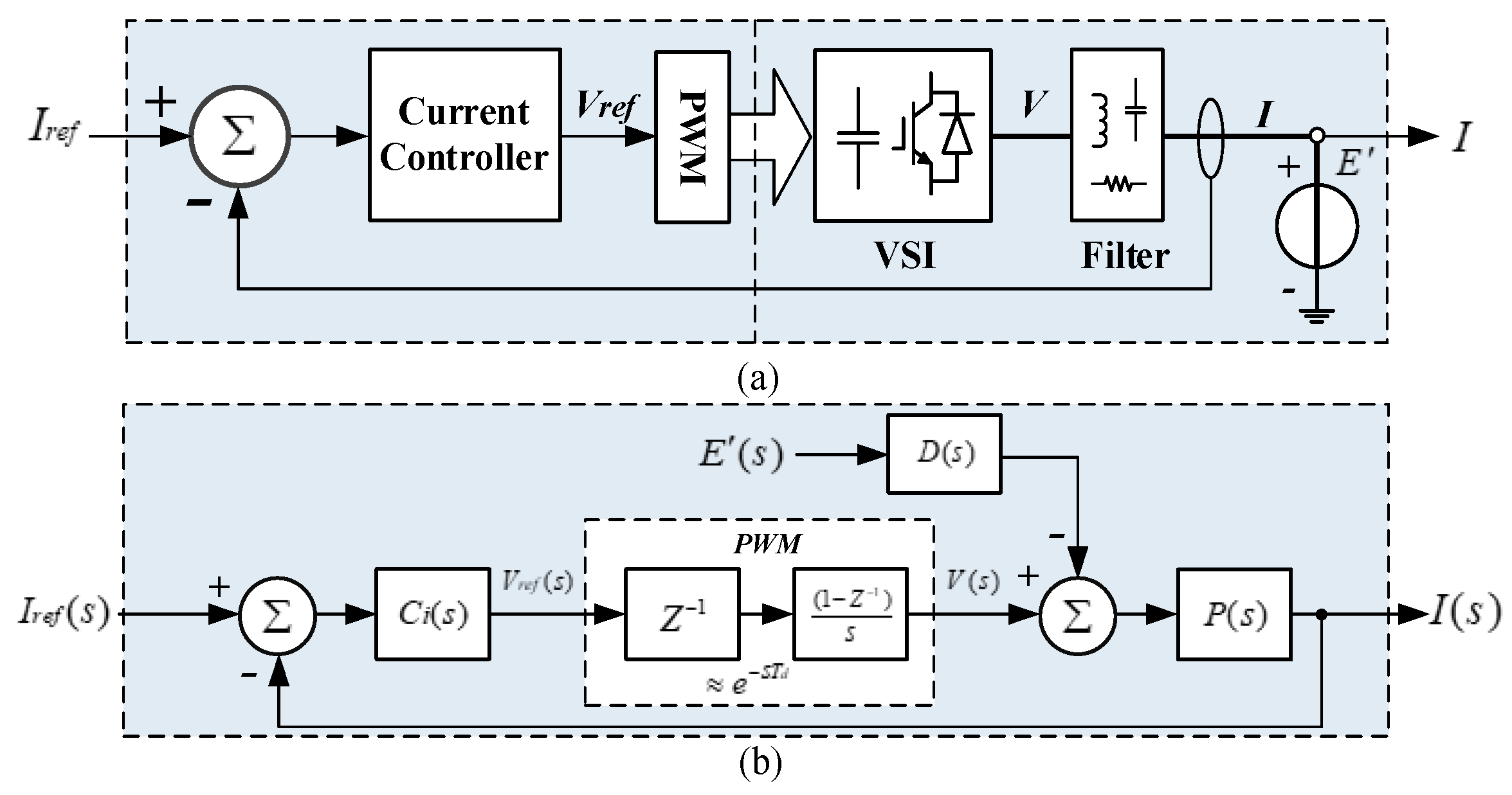
Figure 3. The critical component that determines the stability of the multi-inverter parallel system is the current control layer, which can be described and unified as shown in Figure 4a.
The harmonic instability resulting from the inner control loop is the focus of this paper. In this case, the dynamics of the voltage loop can be ignored, and the DC-link voltages of inverters are assumed to be constant. In addition, the response speed of the inner loop is much faster than that of the phase-lock-loop (PLL); thus, the PLL dynamics are neglected. Based on these two principles, the reference currents are treated as constants.
The control system in Figure 4a can be expressed as a block diagram, as shown in 
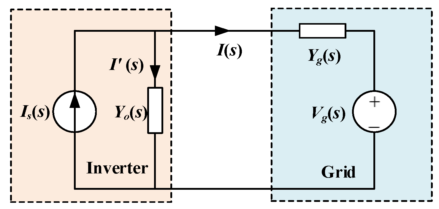
Figure 4b. In the practical application field, the power grid is not ideal, and there is a certain grid impedance, which leads to the output current potentially affecting the PCC voltage, namely, they have a coupling relationship with mutual influence. Therefore, it is difficult to directly analyze the response of the entire system using this control block diagram. The actual output current expression can be written in admittance form, as shown in Equation (1):
I ( s ) = I r e f ( s ) { H ( s ) 1 + H ( s ) } L ( s ) E ( s ) { D ( s ) P ( s ) 1 + H ( s ) } Y ( s ) .
where H ( s ) = C i ( s ) e s T d P ( s ) , L ( s ) = H ( s ) 1 + H ( s ) = C i ( s ) e s T d P ( s ) 1 + C i ( s ) e s T d P ( s ) , and Y ( s ) = 1 Z ( s ) = D ( s ) P ( s ) 1 + C i ( s ) e s T d P ( s ) .
L(s) is the controllable current source gain; Y(s) is the current-loop admittance; Ci(s) is the current-loop controller, such as PR or VPI; D(s) is the current-loop disturbance gain; and P(s) is the controlled object, such as the L or 
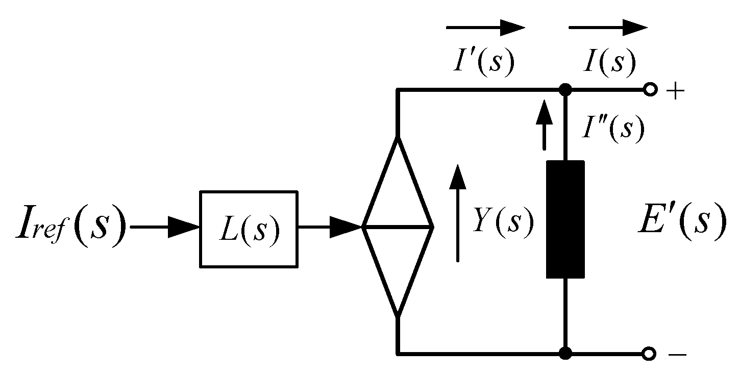
LCL filter. According to Equation (1), the NORTON equivalent model consisting of a controllable current source and current-loop admittance can be obtained from the perspective of circuit port equivalence, as shown in Figure 5. Unlike the current-loop model in block diagram form, that in admittance form can be used to analyze the relationship between the output current and PCC voltage; then, the response expression of each part of the parallel system can be obtained to analyze the stability.
When the L-type filter and VPI are adopted, the current-loop controller can be represented as expressed in Equation (2). Km is the equivalent integral coefficient of each resonant frequency; ωm is the resonant angular frequency; θm is the resonance frequency compensation angle; Td is the control system delay; and L’ and R’ are the inductance and resistance values set based on the zero-polar offset of the controller and the controlled object, respectively:
C i ( s ) = m = 1 n ( K m ( L s + R ) s j ω m e j θ m ) e j s T d .
Because the VPI controller adopts a zero-polar cancellation strategy, that is, (L’s + R’) for the controller and (L’s + R) for the controlled object offset each other, the current-loop admittance using the VPI controller is equal to the product of the P(s) for the controlled object with the disturbance gain and current-loop gain, as shown in Equation (3):
Y V P I ( s ) = D ( s ) P ( s ) 1 + C i ( s ) e s T d P ( s ) = P ( s ) D ( s ) 1 1 + C i ( s ) e s T d P ( s ) .

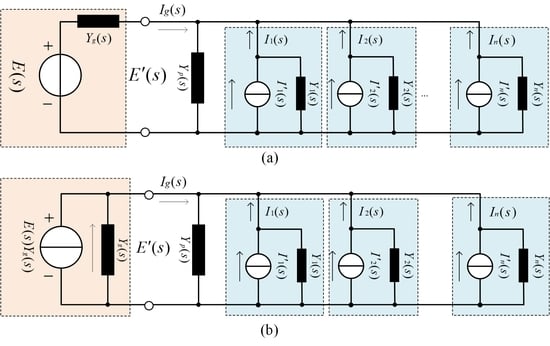
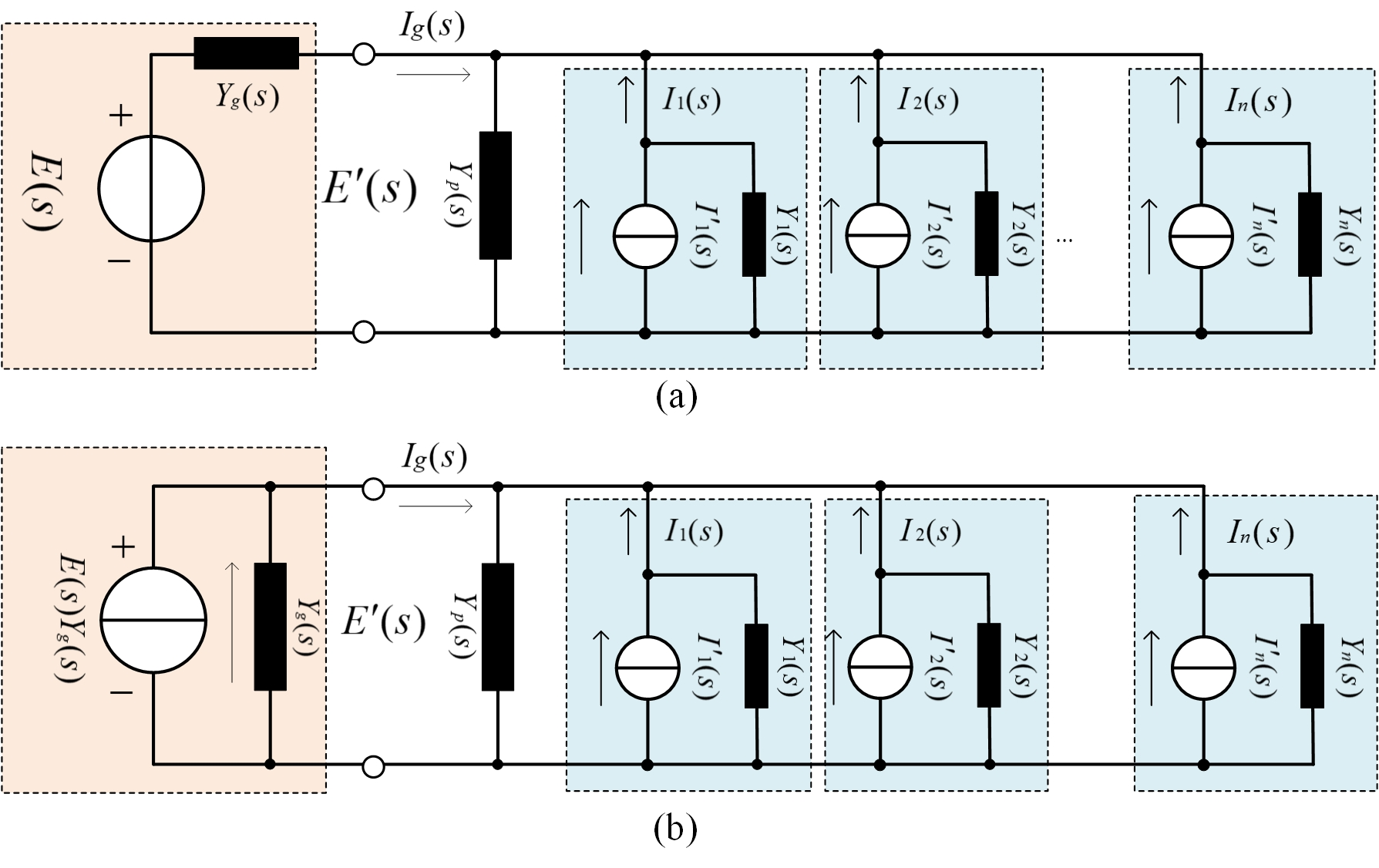
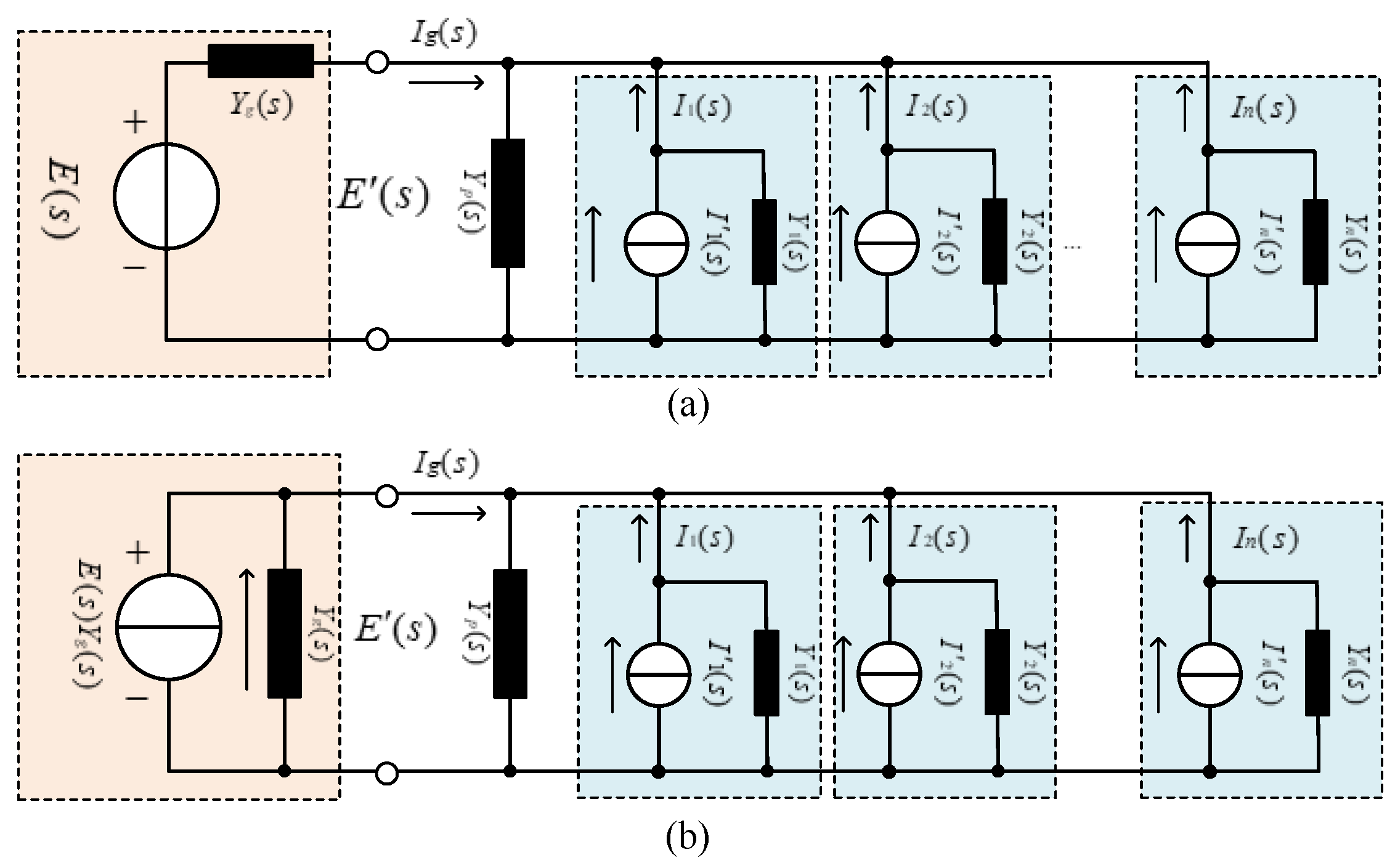
2.3. Admittance Modeling of the VSIs System

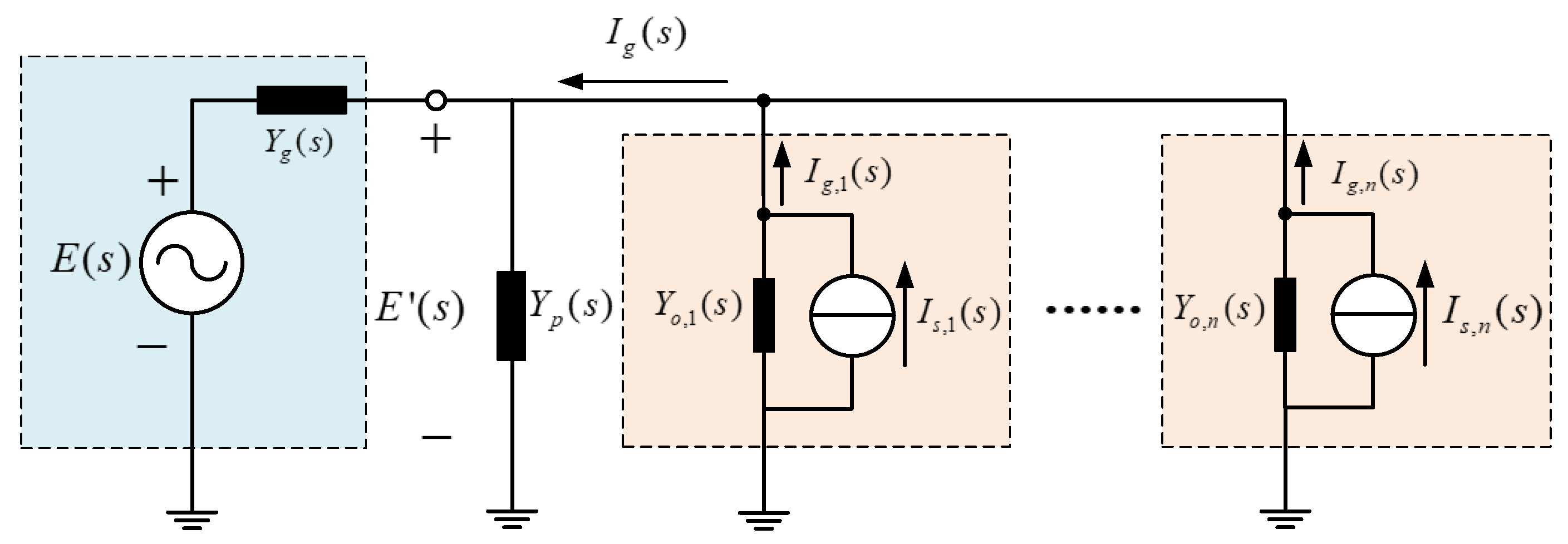
Figure 6a shows the admittance equivalent model of the parallel system. Yp(s) is the equivalent admittance of the passive device at the front side of the power grid; Yg(s) is the equivalent grid admittance; Yn(s) is the current-loop admittance of each module in the parallel system; I′n(s) is the equivalent current source of each module; and In(s) is the actual output current of each module. To facilitate analysis, the voltage source in Figure 6a is converted to the NORTON equivalent form, as shown in Figure 6b. The grid voltage is composed of the equivalent current source, E(s)Yg(s), and the equivalent grid admittance, Yg(s).
According to the superposition principle, the PCC voltage in Figure 6b can be expressed as follows:
E ( s ) = ( E ( s ) Y g ( s ) + m = 1 n I m ( s ) ) / ( Y g ( s ) + Y p ( s ) + m = 1 n Y m ( s ) ) Y t o t a l .
The PCC voltage is obtained through the total excitation and global admittance of the parallel system. The total excitation is determined by the grid voltage, the equivalent grid admittance, and the equivalent current source of each module. The global admittance is composed of the equivalent grid admittance, the equivalent admittance of the passive device, and the equivalent admittance of each module. The influence of grid impedance on the coupling relationship can be analyzed based on Equation (4). When the grid is strong, the grid impedance is close to 0, and the PCC voltage and equivalent current source of each module have no coupling relation; when the grid is weak, the grid impedance cannot be ignored and it constantly changes, and the equivalent current source of each module is coupled with the PCC voltage through the grid impedance.

3. Traditional Impedance-Based Stability Criterion

3.1. Stability Criterion for a Single Grid-Connected Inverter System

The most common model of a power grid for stability analysis involves an admittance, Yg, in series with an ideal voltage source, Vg, and a single grid-connected inverter can be represented as a current source, Is(s), in parallel with an output admittance, Yo(s). An overall single-inverter grid-connected system can be represented as shown in Figure 7.
It is assumed that the grid voltage is stable without a grid-connected inverter and that the inverter is stable when the grid admittance is infinite (the grid impedance equals zero). Based on the equivalent circuit, the inverter output current is as follows:
I ( s ) = ( I s ( s ) Y o ( s ) V g ( s ) ) 1 1 + Y o ( s ) / Y g ( s ) .
Based on Equation (5) and the above two conditions, a single-inverter grid-connected system will remain stable if and only if the ratio of the inverter admittance to the grid admittance (MLG, or Yo(s)/Yg(s)) satisfies the Nyquist criterion.

3.2. Stability Criterion for a Multi-Parallel Grid-Connected Inverter System

The admittance model of a multi-parallel VSI grid-connected system is shown in Figure 8. Yp(s) represents the passive components that are composed of power transformers or reactive compensation components. In such a system, the impedance-based approach for a single-inverter grid-connected system no longer applies.
The authors of [28] proposed a new impedance-based approach for a multi-parallel VSI grid-connected system. The response of the grid-side current of the ith inverter can be derived as follows:
I g , i ( s ) = 1 1 + M L G i ( s ) G c l , i ( s ) I g , i * ( s ) M L G i ( s ) 1 + M L G i ( s ) j = 1 , j i n G c l , j ( s ) I g , j * ( s ) M L G i ( s ) 1 + M L G i ( s ) E ( s ) Y g ( s ) ,
where:
M L G i ( s ) = Y o , i ( s ) Y g ( s ) + Y P ( s ) + j = 1 , j i n Y o , i ( s ) .
In this approach, the output admittance of the ith inverter remains the same, but the grid admittance is replaced by the summation of all the admittances except the output admittance of the ith inverter.
Gcl,i denotes the closed-loop gain of the current control loop, which can be designed to be stable in advance. Similar to the assumption above, all the inverters and grid are individually stable. Thus, the stability of the ith inverter can be predicted as a single-inverter grid-connected system, and a multi-parallel VSI grid-connected system will be stable if all the inverters are stable. It is clear from this approach that analyses must be implemented multiple times to investigate the stability of the entire system, thereby increasing the computational burden. In addition, all the MLGi values must be recalculated when the parameters of the grid and the number of inverters change.

3.3. Unified Impedance-Based Stability Criterion

To reduce the number of calculations and simplify the analysis process, [29] proposed a unified impedance-based stability criterion for a multi-parallel VSI grid-connected system. In this approach, instead of analyzing the response of each grid-side current associated with the ith inverter, the total current from all inverters is derived as follows:
I g ( s ) = [ i = 1 n ( G c l , i ( s ) I g , i * ( s ) Y o , i ( s ) E ( s ) ) ] 1 + ( i = 1 n Y o , i ( s ) + Y p ( s ) ) / Y g ( s ) .
The multi-parallel inverters are still modeled as a current source in parallel with the output admittance. However, the output current of the current source is equal to the summation of Is,i(s), and the output admittance is the summation of Yo,i(s) together with Yp(s). A global (GMLG) is defined as follows:
G M L G ( s ) = j = 1 n Y o , j ( s ) + Y p ( s ) Y g ( s ) .
The multi-parallel VSI grid-connected system can be analyzed by checking whether GMLG(s) satisfies the Nyquist criterion. However, as shown in Equation (9), GMLG(s) in the form of a ratio cannot reflect how an individual inverter affects system stability. The comparison of the two methods is illustrated in Table 1.

4. The Proposed Global Admittance-Based Stability Criterion

4.1. Description of the Basic Principle

The argument principle indicates that when considering a clockwise closed contour, C, in the complex plane mapped through a complex function, G(s)( C i ( s ) e s T d ), the difference between the number of zeros, Z, and poles, P, of G(s) encircled by C is equal to the number of times that the plot of G(s) encompasses the origin clockwise.
The Nyquist criterion is derived from the argument principle. Assuming that the transfer function of a closed-loop system is as follows:
F ( s ) = G ( s ) 1 + G ( s ) H ( s ) ,
where G(s)H(s) is the system open-loop transfer function and H(s) is the negative feedback function. Defining D(s) = 1 + G(s)H(s), the poles of D(s) are the poles of G(s)H(s), and the zeros of D(s) are the poles of F(s) The closed-loop system will be stable if all the poles of F(s) are located in the left half of the panel. In other words, there are no closed-loop poles located in the right half of the panel.
The Nyquist contour, Γs, is a contour that encircles the right half of the complex plane in a clockwise direction. According to the argument principle:
Z = N + P ,
where Z is the number of unstable closed-loop poles (zeros of D(s)), P is the number of unstable open-loop poles (poles of D(s)), and N is the number of times D(s) encircles the origin clockwise, which is equal to the number of times G(s)H(s) encircles (−1, j0) clockwise. The closed-loop system is stable, i.e., Z = 0, when N = −P.
Global admittance, Ytotal(s), is defined as the summation of all the admittances, including the grid admittance, other passive admittances, and output admittances of inverters. Thus, global admittance can be expressed as follows:
Y t o t a l ( s ) = Y g ( s ) + Y p ( s ) + j = 1 n Y o , j .
Based on the admittance model of a multi-parallel VSI grid-connected system, as shown in Figure 6, the output current, Ig,i(s), of the ith inverter can be calculated as follows:
I g , i ( s ) = ( 1 Y o , i ( s ) Y t o t a l ( s ) ) I s , i ( s ) Y o , i ( s ) Y t o t a l ( s ) j = 1 , j i n I s , j ( s ) Y o , i ( s ) Y g ( s ) Y t o t a l ( s ) E ( s ) .
It can be seen from Equation (13) that Ig,i(s) depends on three different excitations, namely, the reference current of the ith inverter, the reference currents of other inverters, and the grid voltage.
The total amount of current from all inverters to the power grid is derived as follows:
I g ( s ) = Y g ( s ) + Y p ( s ) Y t o t a l ( s ) j = 1 n I s , j ( s ) Y g ( s ) Y t o t a l ( s ) j = 1 n Y o , j ( s ) E ( s ) .
Because Yg(s) and Yp(s) are the transfer functions of passive components, they have no right half panel poles. Based on the condition that both the unloaded inverters and grid voltage are stable, Yo,i(s), Is,i(s), and E(s) have no right half plane poles either. Thus, the impact of the numerators in Equation (13) can be neglected when assessing the current stability, and the stability of Ig,i(s) only depends on 1/Ytotal(s); specifically, it depends on the locations of Ytotal(s) zeros.

4.2. The Proposed Stability Criterion

The global admittance-based stability criterion is proposed to assess system stability through the distribution of the zeros of Ytotal(s). The system will be stable only and if only all the zeros of Ytotal(s) are located in the left half panel. An improved Nyquist criterion is proposed to assess the distribution of Ytotal(s) poles. The Nyquist contour, Γs, is still a contour that encircles the right half of the complex plane clockwise. Based on the argument principle, the difference between the zeros and poles of Ytotal(s) in the right panel can be obtained by the number of times that the clockwise Nyquist curve of Ytotal(s) encircles the origin (0, j0). As mentioned above, Yg(s), Yp(s), and Yo,i(s) all have no right half panel poles; thus, Ytotal(s) has no right half panel poles either. Consequently, the number of laps is equal to the number of right half panel zeros of Ytotal(s). The grid-connected system is stable if and only if the Nyquist curve of Ytotal(s) does not encircle the origin (0, j0).
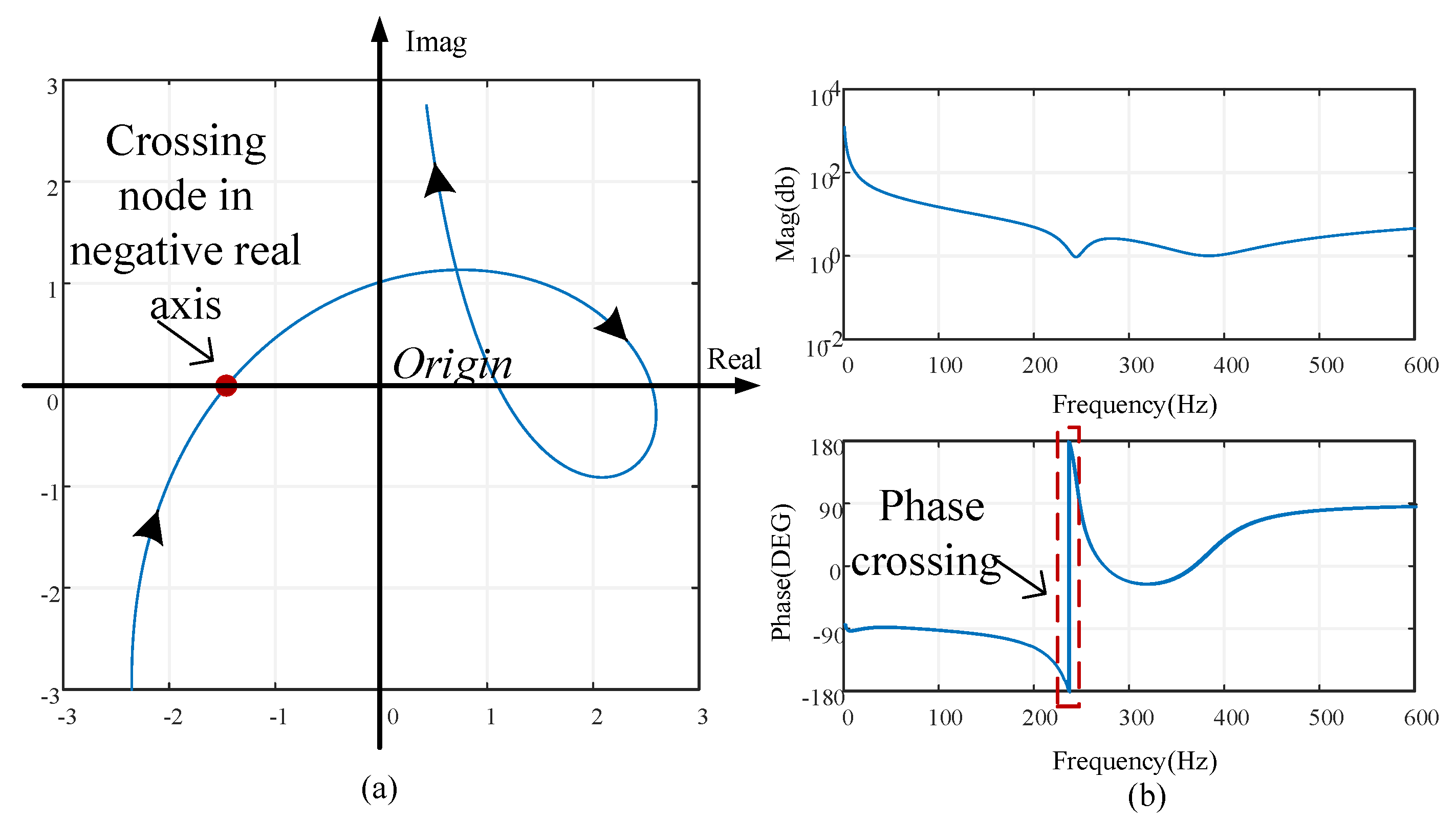
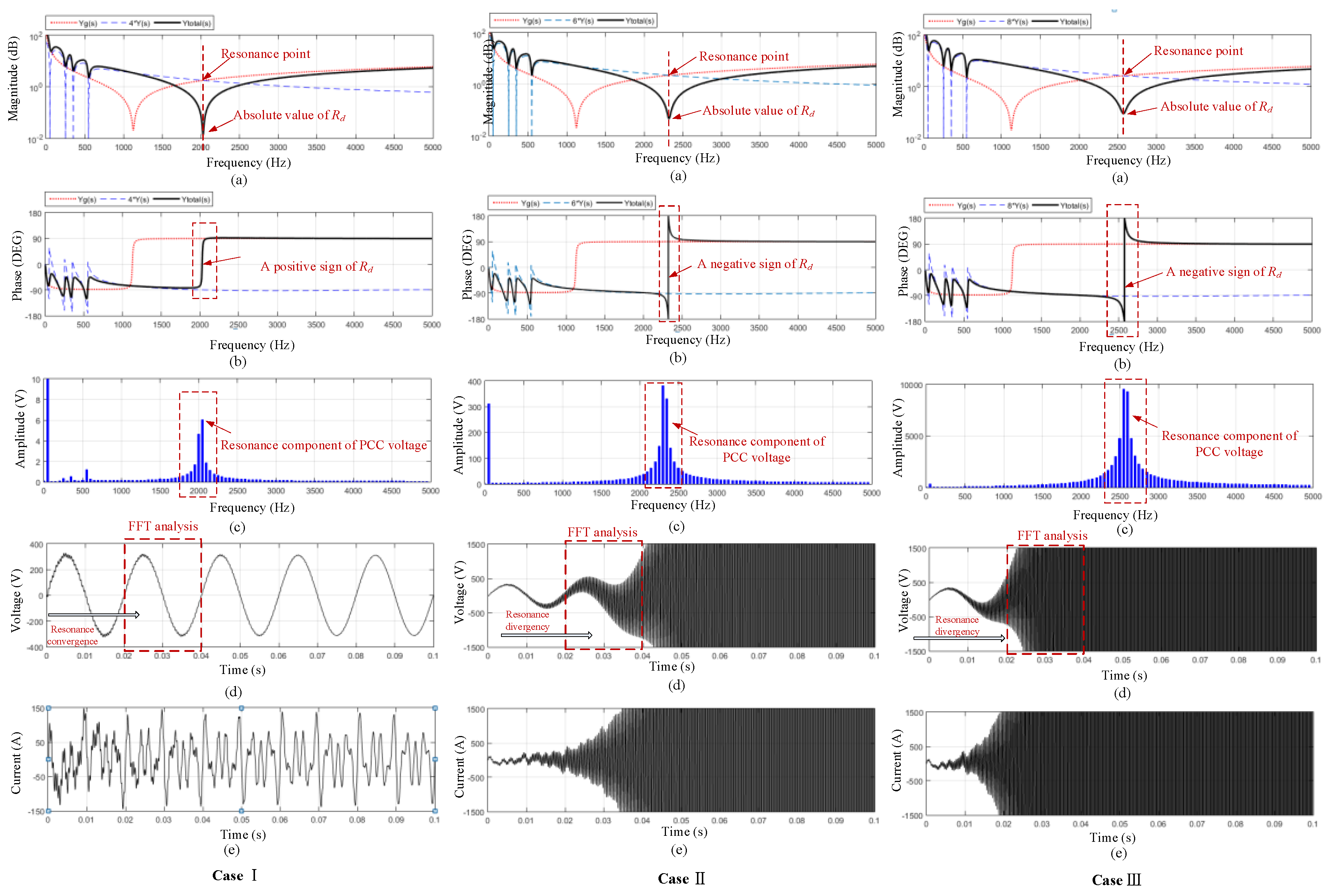
Figure 9 shows Nyquist and Bode plots of Ytotal(s) for an unstable grid-connected system. Figure 9a shows that the Nyquist plot of the unstable system encircles the origin, meeting the improved Nyquist stability criterion. There are multiple intersection points of the Nyquist plot and the real axis; these points are defined as resonance points that determine the system resonance state. The real part of a resonance point is defined as the resonance damping factor, Rd, where:
R d = Y t o t a l ( j ω ) | Im = 0 .
If the minimum Rd is negative, the Nyquist plot encircles the origin (0, j0), reflecting an unstable system. By contrast, if the minimum Rd is positive, this means no encirclement around the origin (0, j0), and the system is stable. The larger the minimum Rd value is, the more stable the system. The authors of [30] proposed a passivity-based stabilization approach for a grid-connected system in which the output admittances of inverters are required to have positive real parts at full frequency. This approach sacrifices the bandwidth of the controller in the purist of stability, and the dynamics of the controller are weakened because of the reduced bandwidth. However, the global admittance-based criterion indicates that the grid-connected system is stable if and only if all the resonance points of Ytotal(s) are located at the right half panel instead of the output admittance of each inverter with a positive real part. Therefore, the bandwidth of the controllers can be designed in a wide frequency domain. Consequently, the dynamics of the inverters can be improved.
Figure 9b shows that the existence of a negative Rd mapped from the Nyquist plot to the Bode plot reflects a step change from −180 to 180° in the phase frequency response curve. Thus, the grid-connected system stability can be predicted based on the Bode plot of Ytotal(s). Compared to the stability criteria proposed in [28,29], global admittance is given in summation form in this case instead of ratio form; this approach not only reduces the computational burden but also reveals the influence of each component on system stability.

4.3. Discussion of the Case in which the Parameters are Different

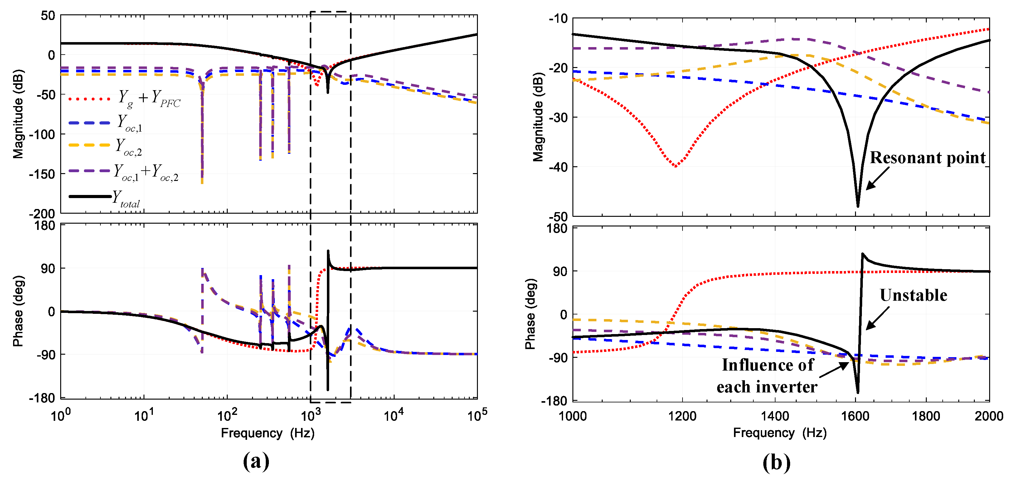
The system stability analysis when inverters with different parameters are connected to the grid is shown in Figure 10 (the parameters are shown in Table 2). It is clear that the system is unstable. Notably, there is a step change from −180 to 180° in the phase frequency response curve of Ytotal at the resonance point, which is approximately 1600 Hz. The phase of each inverter output admittance is different, which means that the influence of each inverter on system instability is different. The real part of the output admittance of each inverter is shown in Table 3, where Rd,1, Rd,2, and Rd,p are expressed in Equations (16) to (18) and the relationship between these variables and Rd is expressed in Equation (19). The real part of the output admittance of inverter 1 at the resonance point is positive, and that of inverter 2 is negative, which implies that inverter 2 is responsible for the system instability.
R d , 1 = Y o c , 1 ( j ω ) | Im ( Y t o t a l ( j ω ) = 0 ) .
R d , 2 = Y o c , 2 ( j ω ) | Im ( Y t o t a l ( j ω ) = 0 ) .
R d , p = ( Y g ( j ω ) + Y P F C ( j ω ) ) | Im ( Y t o t a l ( j ω ) = 0 ) .
R d = R d , 1 + R d , 2 + R d , p .
The global admittance-based method together with methods using MLGi and GMLG can be used to concisely and accurately make predictions involving interconnected systems. However, the global admittance-based method can clearly and directly reveal the effects of each component. In addition, the global admittance-based method provides a simple and efficient stability-oriented design.

5. Simulation and Experimental Results

To verify the validity and rationality of the proposed harmonic stability criterion, a MATLAB-based model and 400 kVA/400 V multi-parallel grid-connected VSI experiment system were established. In the simulation, as the number of paralleled VSIs increases, an unstable phenomenon may occur if the grid impedance remains constant. In the experiment, the global admittance was changed by varying the capacitance value of grid impedance, which will lead to harmonic instability. The stability criterion proposed in this paper can be used to analyze the system instability and provide theoretical support for resonance suppression.

5.1. Simulation Verification

Case I provides an example in which four inverters were connected to the grid. The frequency analysis plot and simulation results are shown in Figure 11, and the magnitude–frequency curve of the studied system is shown. The dotted line represents the grid admittance, Yg(s), the dashed line represents the total output admittance of the four inverters, 4*Y(s), and the solid line represents the global admittance, Ytotal(s). The interaction of Yg(s) and 4*Y(s) is the resonance point of the system, and the corresponding frequency is the resonance frequency. The resonance frequency of the four-parallel VSI system is approximately 2000 Hz. The magnitude of Ytotal(s) at the resonance frequency is the absolute value of Rd and equals 0.02. The sign of Rd can be obtained from the phase–frequency curve of Ytotal(s), as shown in (b). The step changes from −90 to 90° in the phase curve of Ytotal(s) indicates that the sign of Rd is positive, which indicates that the four-parallel grid-connected system is stable. The fast Fourier transform (FFT) analysis of the PCC voltage is shown in (c). Resonance occurs at 2000 Hz, and the amplitude of the resonance component is only 6 V. The PCC voltage and total current from the inverters are stable, as shown in (d) and (e), respectively, and these findings are consistent with the anticipated results.
In case II, a six-paralleled VSI grid-connected system was investigated considering the proposed stability criterion. The frequency analysis and simulation results are shown in Figure 11 (case II). The dashed line represents the total output admittance of the six inverters, 6*Y(s), and the dotted line and solid line have the same meaning as those in Figure 11 (case I). The conclusion can be obtained from (a) that the absolute value of Rd is 0.1 and the resonance frequency equals 2250 Hz. The step changes from −180 to 180° in the phase-frequency plot of Ytotal(s) in (b) imply that the sign of Rd is negative, and Rd equals −0.1. Based on the global admittance-based stability criterion, the six-parallel VSI grid-connected system is unstable. The FFT analysis of the PCC voltage is shown in (c). The amplitude of the resonance component is close to 400 V, which is even larger than that of the fundamental component. The simulation results of the PCC voltage and the total current from inverters, as shown in (d) and (e), respectively, indicate that the system starts losing stability at approximately 0.2 s.
In case III, the stability of an eight-paralleled VSI grid-connected system was studied. The frequency analysis and simulation results are shown in Figure 11 (case III), from which the following information of the system can be obtained: Rd equals −0.6, the resonance frequency is 2250 Hz, the amplitude of the resonance component of the PCC voltage is close to 10,000 V, and the instability occurs at 0.02 s. By comparing the above data with those in case I and case II, the following conclusions can be drawn. Rd decreases as the number of inverters increases. The system will be unstable if Rd is less than zero. The resonance frequency and the amplitude of the resonance component of the PCC voltage increase as Rd decreases. The smaller Rd is, the shorter the time that the instability occurs. The conclusions of the three cases are shown in Table 4.

5.2. Experimental Verification

Figure 12 shows the 400 kVA/400 V experimental platform, which consists of six grid-connected VSIs. The controller of the VSI unit is based on DSP (TMS320F2812) and FPGA (EP2C5Q208C8). The specific schematic diagram of the parallel system is shown in Figure 13. By changing the capacitance value (controlled by S1–S3) of grid impedance, the global admittance and resonance frequency are changed, which will lead to harmonic instability (when the resonance frequency enters the current-loop bandwidth). By changing the resistance value (R1~R3) of the grid impedance, the real value of the resonance point is changed, which will result in a stable parallel system (when Rd > 0).
Figure 14 and Figure 15 show the experimental waveforms. When the global admittance changes, harmonic instability occurs in the parallel system, and the resonant frequency is approximately 550 Hz; when C = 600 µF and R = 0.6 Ω, as the system damping increases, Rd > 0, and the parallel system becomes stable, which verifies the effectiveness of the proposed analysis method.

6. Conclusions

The global admittance-based stability criterion has been proposed in this paper, which adopts the frequency characteristics of the summation of all the admittances to assess system stability. The stability can be predicted by determining whether the Nyquist plot of global admittance encircles the origin (0, j0). The resonance point and resonance damping factor have been defined as well, and then the stability criterion has been extended to obtain the locations of resonance points. The global admittance has been given in summation form instead of ratio form, which not only reduces the computational burden but also reflects the effects of each component on the system stability. The criterion also provides a stability-oriented design guideline and indicates that the system will be stable if and only if all the resonance points are located in the right half panel. Compared to the passivity-based stabilization method, which requires the output admittances of all the inverters to have positive real parts at full frequency, this criterion expands the selection of the controller bandwidth, leading to an improvement in system dynamics. Simulations and experiments have been implemented to verify the proposed method.

Author Contributions

Conceptualization, W.C. and K.L.; data curation, S.W.; funding acquisition, J.Z.; methodology, S.W. and H.K.; software, H.K. and D.F.; validation, S.W.; writing—original draft, K.L., S.W., and H.K.; writing—review and editing, K.L.

Funding

This research was supported in part by the National Natural Science Foundation of China (Grant Number 51607037), Project funded by China Postdoctoral Science Foundation (Grant Number 2018M642138), and the Fundamental Research Funds for the Central Universities (Grant Number 2242019R20010).

Conflicts of Interest

The authors declare no conflicts of interest.

References

  1. Blaabjerg, F.; Chen, Z.; Kjaer, S.B. Power electronics as efficient interface in dispersed power generation systems. IEEE Trans. Power Electron. 2004, 19, 1184–1194. [Google Scholar] [CrossRef]
  2. Rocabert, J.; Luna, A.; Blaabjerg, F.; Rodríguez, P. Control of Power Converters in AC Microgrids. IEEE Trans. Power Electron. 2012, 27, 4734–4749. [Google Scholar] [CrossRef]
  3. Liserre, M.; Teodorescu, R.; Blaabjerg, F. Stability of photovoltaic and wind turbine grid-connected inverters for a large set of grid impedance values. IEEE Trans. Power Electron. 2006, 21, 263–272. [Google Scholar] [CrossRef]
  4. Turner, R.; Walton, S.; Duke, R. Stability and Bandwidth Implications of Digitally Controlled Grid-Connected Parallel Inverters. IEEE Trans. Ind. Electron. 2010, 57, 3685–3694. [Google Scholar] [CrossRef]
  5. Wang, F.; Duarte, J.L.; Hendrix, M.A.M.; Ribeiro, P.F. Modeling and Analysis of Grid Harmonic Distortion Impact of Aggregated DG Inverters. IEEE Trans. Power Electron. 2011, 26, 786–797. [Google Scholar] [CrossRef]
  6. Wang, X.; Blaabjerg, F.; Chen, Z. Autonomous Control of Inverter-Interfaced Distributed Generation Units for Harmonic Current Filtering and Resonance Damping in an Islanded Microgrid. IEEE Trans. Ind. Appl. 2014, 50, 452–461. [Google Scholar] [CrossRef]
  7. Zhang, H.; Wang, X.; Harnefors, L.; Gong, H.; Hasler, J.; Nee, H. SISO Transfer Functions for Stability Analysis of Grid-Connected Voltage-Source Converters. IEEE Trans. Ind. Appl. 2019, 55, 2931–2941. [Google Scholar] [CrossRef]
  8. Wang, X.; Blaabjerg, F.; Wu, W. Modeling and Analysis of Harmonic Stability in an AC Power-Electronics-Based Power System. IEEE Trans. Power Electron. 2014, 29, 6421–6432. [Google Scholar] [CrossRef]
  9. Turner, R.; Walton, S.; Duke, R. A case study on the application of the Nyquist stability criterion as applied to interconnected loads and sources on grids. IEEE Trans. Ind. Electron. 2013, 60, 2740–2749. [Google Scholar] [CrossRef]
  10. Cao, W.; Fan, D.; Liu, K.; Zhao, J.; Ruan, L.; Wu, X. Harmonic Stability Assessment based on Global Admittance for Multi-Paralleled Grid-Connected VSIs using Modified Nyquist Criterion. In Proceedings of the International Power Electronics Conference (IPEC-Niigata 2018 -ECCE Asia), Niigata, Japan, 20–24 May 2018. [Google Scholar]
  11. Wang, X.; Blaabjerg, F. Harmonic Stability in Power Electronic-Based Power Systems: Concept, Modeling, and Analysis. IEEE Trans. Smart Grid. 2019, 10, 2858–2870. [Google Scholar] [CrossRef]
  12. Hu, T. A Nonlinear-System Approach to Analysis and Design of Power-Electronic Converters with Saturation and Bilinear Terms. IEEE Trans. Power Electron. 2011, 26, 399–410. [Google Scholar] [CrossRef]
  13. Wu, H.; Pickert, V.; Giaouris, D.; Ji, B. Nonlinear Analysis and Control of Interleaved Boost Converter Using Real-Time Cycle to Cycle Variable Slope Compensation. IEEE Trans. Power Electron. 2017, 32, 7256–7270. [Google Scholar] [CrossRef]
  14. Amin, M.; Molinas, M. Small-Signal Stability Assessment of Power Electronics Based Power Systems: A Discussion of Impedance- and Eigenvalue-Based Methods. IEEE Trans. Ind. Appl. 2017, 53, 5014–5030. [Google Scholar] [CrossRef]
  15. Kalcon, G.O.; Adam, G.P.; Anaya-Lara, O.; Lo, S.; Uhlen, K. Small-Signal Stability Analysis of Multi-Terminal VSC-Based DC Transmission Systems. IEEE Trans. Power Syst. 2012, 27, 1818–1830. [Google Scholar] [CrossRef]
  16. Pinares, G.; Bongiorno, M. Modeling and Analysis of VSC-Based HVDC Systems for DC Network Stability Studies. IEEE Trans. Power Deliv. 2016, 31, 848–856. [Google Scholar] [CrossRef]
  17. Beerten, J.; D’Arco, S.; Suul, J.A. Identification and Small-Signal Analysis of Interaction Modes in VSC MTDC Systems. IEEE Trans. Power Deliv. 2016, 31, 888–897. [Google Scholar] [CrossRef]
  18. Kundur, P. Power System Stability and Control; McGraw-Hill: New York, NY, USA, 1994. [Google Scholar]
  19. Middlebrook, R.D.D. Input filter consideration in design and application of switching regulators. In Proceedings of the IEEE Industry Applications Society Annual Meeting, Chicago, IL, USA, 11–14 October 1976. [Google Scholar]
  20. Cao, W.; Ma, Y.; Yang, L.; Wang, F.; Tolbert, L.M. D-Q Impedance Based Stability Analysis and Parameter Design of Three-Phase Inverter-Based AC Power Systems. IEEE Trans. Ind. Electron. 2017, 64, 6017–6028. [Google Scholar] [CrossRef]
  21. Cao, W.; Ma, Y.; Wang, F. Sequence-Impedance-Based Harmonic Stability Analysis and Controller Parameter Design of Three-Phase Inverter-Based Multibus AC Power Systems. IEEE Trans. Power Electron. 2017, 32, 7674–7693. [Google Scholar] [CrossRef]
  22. Cho, Y.; Hur, K.; Kang, Y.C.; Muljadi, E. Impedance-Based Stability Analysis in Grid Interconnection Impact Study Owing to the Increased Adoption of Converter-Interfaced Generators. Energies 2017, 10, 1355. [Google Scholar] [CrossRef]
  23. Liu, Z.; Liu, J.; Bao, W.; Zhao, Y. Infinity-norm of impedance-based stability criterion for three-phase AC distributed power systems with constant power loads. IEEE Trans. Power Electron. 2015, 30, 3030–3043. [Google Scholar] [CrossRef]
  24. Vesti, S.; Suntio, T.; Oliver, J.A.; Prieto, R.; Cobos, J.A. Impedance-based stability and transient-performance assessment applying maximum peak criteria. IEEE Trans. Power Electron. 2013, 28, 2099–2104. [Google Scholar] [CrossRef]
  25. Suntio, T.; Messo, T.; Berg, M.; Alenius, H.; Reinikka, T.; Luhtala, R.; Zenger, K. Impedance-Based Interactions in Grid-Tied Three-Phase Inverters in Renewable Energy Applications. Energies 2019, 12, 464. [Google Scholar] [CrossRef]
  26. Sun, J. Impedance-based stability criterion for grid-connected inverters. IEEE Trans. Power Electron. 2011, 26, 3075–3078. [Google Scholar] [CrossRef]
  27. Liu, F.; Liu, J.; Zhang, H.; Xue, D. Stability issues of Z + Z type cascade system in hybrid energy storage system (HESS). IEEE Trans. Power Electron. 2014, 29, 5846–5859. [Google Scholar] [CrossRef]
  28. Wang, X.; Blaabjerg, F.; Liserre, M.; Chen, Z.; He, J.; Li, Y. An active damper for stabilizing power-electronics-based AC systems. IEEE Trans. Power Electron. 2014, 29, 3318–3329. [Google Scholar] [CrossRef]
  29. Ye, Q.; Mo, R.; Shi, Y.; Li, H. A unified Impedance-based Stability Criterion (UIBSC) for paralleled grid-tied inverters using global minor loop gain (GMLG). In Proceedings of the IEEE Energy Conversion Congress and Exposition (ECCE), Montreal, QC, Canada, 20–24 September 2015. [Google Scholar]
  30. Harnefors, L.; Wang, X.; Yepes, A.G.; Blaabjerg, F. Passivity-Based Stability Assessment of Grid-Connected VSCs-An Overview. IEEE J. Emerg. Sel. Top. Power Electron. 2016, 4, 116–125. [Google Scholar] [CrossRef]
Figure 1. Fundamental configuration of a multi-parallel grid-connected VSI system.
Energies 12 02687 g001
Figure 2. Simplified multi-parallel grid-connected VSI system considering the grid impedance.
Energies 12 02687 g002
Figure 3. Unified diagram of the stability problem in various application fields.
Energies 12 02687 g003
Figure 4. Control system of an inverter. (a) Simplified block diagram; (b) Schematic diagram.
Energies 12 02687 g004
Figure 5. Current-loop model- admittance form of a single-inverter system.
Energies 12 02687 g005
Figure 6. Equivalent circuit of a parallel system. (a) Voltage-source form and (b) current-source form.
Energies 12 02687 g006
Figure 7. Model of a single-inverter grid-connected system.
Energies 12 02687 g007
Figure 8. Admittance representation of a multi-parallel VSI grid-connected system.
Energies 12 02687 g008
Figure 9. Nyquist and Bode plots of global admittance Ytotal(s) for an unstable grid-connected system. (a) Nyquist curve; (b) Bode plots.
Energies 12 02687 g009
Figure 10. Stability analysis using Bode plots when VSIs have different parameters (an unstable case). (a) Bode plots; (b) zoom of dotted box in (a).
Energies 12 02687 g010
Figure 11. Frequency analysis and simulation results of four (case I), six (case II), and eight (case III) parallel VSI systems. (a) Amplitude–frequency plot; (b) phase–frequency plot; (c) FFT analysis of the PCC voltage; (d) PCC voltage; (e) total output current.
Energies 12 02687 g011
Figure 12. Experiment platform. (a) Multi-parallel grid-connected VSIs; (b) VSI unit; (c) ScopeCorder-DL850E.
Energies 12 02687 g012
Figure 13. Multi-parallel grid-connected VSI system with adjustable grid impedance.
Energies 12 02687 g013
Figure 14. Experimental waveform when the grid impedance changes (C = 600 µF, R = 0.2 Ω, Resonance frequency: 11th). (a) The waveform when the harmonic instability occurs; (b) zoom of dotted box in (a).
Energies 12 02687 g014
Figure 15. Experimental waveform when the grid impedance changes (C = 600 µF, R = 0.6 Ω). (a) The waveform when the system becomes stable; (b) zoom of dotted box in (a).
Energies 12 02687 g015
Table 1. Comparison of two methods.
MethodCalculation BurdenReflect the Instability-Causing ElementEase of Stability-Oriented Redesign
MLGmassivepositivedirect
GMLGsmallnegativecomplicated
Table 2. Parameters of the inverter system.
ParametersValues
Inverter 1LCL-filterLf,11.3 mH
RLf,10.1 Ω
Cf,13 μF
Lg,11.5 mH
RLg,10.2 Ω
PR current controllerKp,110.5
Ki,12000
Ki,5500
Ki,7500
Ki,11500
Inverter 2LCL-filterLf,21.5 mH
RLf,20.1 Ω
Cf,24.7 μF
Lg,21.8 mH
RLg,20.2 Ω
PR current controllerKp218
Ki,23000
Ki,5500
Ki,7500
Ki,11500
DC-link voltageVdc700 V
GridLs0.6 mH
Rs0.2 Ω
PFC device capacityYPFC30 μF
Table 3. Different real part of admittance.
ωf (Hz)RdRd,1Rd,2Rd, p
1600−0.00410.0038−0.01330.0054
Table 4. Conclusions of the three cases.
CaseNumber of InvertersResonance FrequencyRdSystem Stability
I42000 Hz0.02stable
II62250 Hz−0.1unstable
III82250 Hz−0.6unstable

