Article

Design and Analysis of New Harbour Grid Models to Facilitate Multiple Scenarios of Battery Charging and Onshore Supply for Modern Vessels

School of Technology and Innovations, University of Vaasa, 65200 Vaasa, Finland
*
Author to whom correspondence should be addressed.
Energies 2019, 12(12), 2354; https://doi.org/10.3390/en12122354
Submission received: 24 May 2019 / Revised: 17 June 2019 / Accepted: 17 June 2019 / Published: 19 June 2019
(This article belongs to the Section D: Energy Storage and Application)

Abstract

:
The main objective of this study is to develop and analyse different harbour grid configurations that can facilitate the charging of batteries for modern vessels and supply onshore power. The use of battery energy storage systems in modern hybrid or entirely electric vessels is rapidly increasing globally in order to reduce emissions, save fuel and increase energy efficiency of ships. To fully utilise their benefits, certain technical issues need to be addressed. One of the most important aspects is to explore alternative ways of charging batteries with high power capacities for modern vessels. The paper presents a comprehensive overview of battery-charging configurations and discusses the technical challenges of each design from the perspective of their practical implementation, both onshore and onboard a vessel. It is found that the proposed models are suitable for vessels operating either entirely on battery storage or having it integrated into the onboard power system. Moreover, the proposed charging models in a harbour area can solve the problem of charging batteries for future hybrid and electric vessels and can open new business opportunities for ship owners and port administrators. The performance of the proposed models is validated by simulating two case studies in PSCAD: slow charging (based onshore) and fast charging (based onboard).

Graphical Abstract

1. Introduction

Maritime shipping is the most common form of global trade, but it is searching for solutions to cope with the key challenges of stringent environmental air pollution, increasing energy efficiency, and independence from fossil fuels [1,2,3,4,5,6]. Moreover, electrification in the transportation sector will incorporate carbon-free electricity generation from renewables and from sustainable energy sources such as wind and solar [7,8]. The stricter emission rules set by the International Maritime Organisation (IMO) [1] and the EU Directive 2005/33/EC [9] are forcing ships to use cleaner fuels and sustainable energy sources for manoeuvring as well as during their stay at berth. The main contributors to emission footprints and overall energy efficiency of vessels are the power supply system and energy conversion systems being employed onboard the vessel. In this respect, the future development of shipping technology will be towards converting from conventional fossil-fuel-based vessel power systems to new build or retrofitted elements using renewable, sustainable, energy-efficient, less polluting and more cost-effective energy resources [10]. The life cycle assessment of new build and retrofitted marine power systems reveals that they consume less fuel (8.28 and 29.7% less, respectively) and produce lower emissions (5.2–16.6% and 29.7–55.5% less, respectively), compared to the marine power system of a conventional vessel used as a reference [11].
The history of the development of ship electrical systems is presented in [12], which notes that solid-state power electronics technology opened a new era, leading to the marine vessels known as all-electric ships (AESs). Shipboard power systems have developed from thermal to electrochemical, stored and hybrid power systems [4,13]. The modern AES has an integrated power system consisting of several generators including renewable sources and energy storage; it behaves like an islanded microgrid with a power capacity of up to 100 MW [14,15,16,17,18,19,20,21,22]. The AES is believed to be the most efficient ship, replacing the conventional mechanical drive system with electric propulsion. The AES concept has become the standard for large cruise ships, adopted by the major shipyards in the world [19], and is also applied on shuttle tankers, ferries and other special types of vessels [20]. Battery energy storage systems (BESSs) can play a significant role in the hybrid power system of vessels, serving various purposes such as increasing energy efficiency, improving dynamic performance, peak shaving and spinning reserve [16,23,24,25,26]. BESSs for marine applications should have a high energy density and a large discharge time, combined with the characteristic of a flat voltage-drop curve versus time [25,27]. Lithium-ion batteries are a well-established technology, having high efficiency, high power and high energy density [28,29]; these characteristics make their use feasible for electric vehicles [27,30] and for several types of ships in the marine industry [18,23,26]. Moreover, the flexible charging patterns can be used for the smart charging systems of BESSs to enable higher penetration of renewable energy resources [31,32].
An existing conventional vessel can be converted to either a hybrid vessel, by integrating a BESS with diesel generators, or to an electric vessel, by replacing the diesel generator entirely with a BESS [33]. As examples, a sailing boat [34] in an Italian harbour is likely to replace a diesel generator with a BESS along with renewable sources in the vessels. A hybrid green ship (PV/diesel) [35] in the island of Geoje, South Korea shows there is a viable option of retrofitting photovoltaic generation and a BESS alongside the diesel engine of a ship. Broadly, it has been observed that the number of battery-operated vessels has increased greatly during the last five years [36]. Shipping technology has progressed very rapidly, mainly in the areas of propulsion and power supply topologies [37]. In the coming few years, research and development in multiple technologies such as BESS, power electronics and information technology can open a modern era for vessels by employing wireless charging of batteries [38], as well as real-time measurement and monitoring of the fundamental ship parameters [12].
Modern vessels with small power capacities that operate entirely on a BESS are known as electric vessels, whereas large ships employing integrated power systems including BESSs are called hybrid vessels. Hybrid vessels can reduce fuel consumption and emissions by approximately 10–35% using advanced control strategies [13] and optimal operation of electric power generation for minimising cost by employing BESSs [5,26]. Before the development of integrated power systems for vessels, it was not possible to gain the full potential of electric ship technology [39]. Moreover, research shows that integrating emerging technologies such as photovoltaic systems and BESSs with cold-ironing practices and with the existing marine power plants can significantly reduce contributions to global warming, human toxicity, acidification and eutrophication by around 4–7 orders of magnitude; in addition, it will reduce fuel consumption and increase overall performance [40]. These modern vessels will require charging stations in ports for frequent recharge of battery storage. Therefore, the harbour area grid must be designed to accommodate charging of batteries, especially for hybrid and electric vessels, in addition to cold-ironing [10,33]. The process of shutting down auxiliary diesel engines of ships and obtaining an onshore power supply for the ships’ auxiliary services during a stay in port is historically termed ‘cold-ironing’ or ‘onshore power supply’ or ‘shore-to-ship power’ [6,33,34,41]. The current high-voltage shore connection (HVSC) standard [42] has been developed and unanimously adopted by world leading organisations, namely the IEC, ISO and IEEE, for promoting shore-to-ship power supply. Shore-to-ship power supply is an emerging paradigm [43], and the use of energy storage at harbours can reduce air emissions as well as facilitate the power generation with respect to optimal loading [44].
A BESS employed by modern vessels needs to be recharged after reaching a certain depth of discharge. Although the concept of the harbour area smart grid (HASG) [33] facilitates the charging of batteries for vessels in addition to supplying shore-to-ship power, a detailed analysis of charging methodologies and alternative charging scenarios has not been provided yet. A review of the literature [10,24,26,33,36,41,44] leads to the following research questions:
  • What are the suitable options for charging the batteries for the vessels?
  • What are the key features and technical challenges of alternative methods for charging the batteries?
  • How can these different charging scenarios be applied practically?
The main objective of this study is to address the above questions by presenting new harbour grid models that incorporate various battery-charging scenarios with shore-to-ship power supply. Among these charging configurations, the two most popular (slow and fast charging) are investigated in this study, based on discussions with marine industry experts. Their feasibility and performance are validated by PSCAD simulations. The results show that the performance of these models is quite satisfactory and can be practically implemented.
The rest of this paper is organised as follows. Section 2 focuses on battery-charging methods. In Section 3, alternative ways of charging the batteries and supplying onshore power are explained in detail along with the key characteristics and technical challenges of implementing each scenario. Section 4 presents the results and monitors the performance and validity in two case studies. Section 5 discusses the key findings of the research and Section 6 concludes with the key features of each scenario along with future research directions.

2. Charging Methods

The charging methods for batteries can be divided into two broad categories, according to the time required; these are designated slow and fast charging. Slow charging of batteries is usually done in 8 h or more, while fast charging is accomplished within 1 h or less. However, these times depend on how fast the charging is required for a particular vessel type and its stay time at a particular harbour. In this paper, the fast charging time of 2 h is considered, which is typical for large cruise ships with regular routes connecting major cities in the Baltic Sea. In general, charging at such a high rate and with such a high voltage is not permitted because it may cause overcharging and overheating of the batteries beyond allowed limits, consequently reducing the battery life and possibly causing premature failure. The basic requirement to charge a battery is to connect a DC current source of a voltage higher than the open circuit voltage of the battery. AC ripple in the charging voltage and current should be kept below 4 and 5%, respectively, to avoid potential temperature rise (as recommended by battery manufacturers [45]); however, AC ripple added to DC voltage and current has no significant effect on battery life [46].
Many different charging methods and algorithms have been proposed, which greatly depend upon the type of battery and its chemistry; their aims are to improve charging time, efficiency and cycle life. These methods include single- and multirate constant current, constant current–constant voltage, double-loop control, fuzzy logic control, boost charge and pulse charge [45,47]. The most recommended and most popular method for both lithium-ion and lead-acid batteries is constant current–constant voltage (CC/CV) charging [45,47,48]. The sequence of CC/CV charging is divided into four stages [48]: trickle charge, constant current, constant voltage and charge termination. Trickle charge is used to restore deeply depleted batteries until a certain voltage threshold (80% of nominal voltage) is reached. After trickle charge, the batteries are charged with a constant current of 0.1–1 C (10–100% of rated current) depending on whether slow or fast charging is required. With constant-current charging at some selected rate, the battery voltage and charger voltage increase gradually until a maximum battery voltage (115% of nominal voltage) is reached. In constant-current charging of lithium-ion batteries, a current higher than 1 C should be avoided because it does not decrease the total charging time, but rather results in an overvoltage [48]. After reaching a voltage corresponding to 90–95% state-of-charge (SOC), the charging rate is either decreased to 0.02–0.07 C or the charging process is completely terminated. Lead-acid batteries are kept on trickle charge before charge termination [45]; however, for lithium-ion batteries, trickle charge before termination is not recommended because it can cause plating of metallic lithium, resulting in sudden disassembly of the battery [48].
In this work, simulation models of the chargers created with PSCAD software have been designed to provide a constant current of 0.1 C for 10 h of slow charging and a constant current of 0.5 C for 2 h of fast charging. These C rates provide a constant current of 290 A for offboard slow charging and 1450 A for onboard fast charging, for a set of three 2 MWh BESSs charged to a voltage of 0.69 kV; this configuration meets the standard requirements for low-voltage shore connection at ports [49]. In both slow- and fast-charging methods, the chargers are capable of providing the required DC voltage and current for charging batteries at any particular initial state-of-charge. Moreover, the SOC is typically estimated using model-based estimators [50,51,52]; however, in this paper it is considered by using terminal voltage. The nominal voltage selected for a 2 MWh battery is 0.6 kV and the battery achieves a maximum voltage of 0.69 kV at 100% SOC. Although the constant current–constant voltage method is recommended for batteries, only the constant-current stage (leading to a specified SOC) was simulated in our model because of limited simulation/computation time with the PSCAD software. Because charging rates of less than 1 C are recommended and therefore adopted for this study, it is assumed that there will be no temperature rise or overvoltage that will cause a major effect on the life cycle of the batteries. The chargers are modelled in PSCAD using a detailed type configuration of a three-phase AC–DC converter followed by a DC link, and high-frequency, transformer-isolated DC–DC converter to control the charging current.

3. Analysis of Multiple Battery-Charging Scenarios and Onshore Power Supply

This section discusses alternative ways of charging the batteries in addition to supplying shore-to-ship power and follows the concept of the HASG. Although the concept of the HASG has already been presented in [33], here it has been modified to take into account the realistic dimensions of components in use at harbours, such as the size and length of cables, ratings of transformers and other equipment. We keep in mind that an actual harbour area grid can benefit from any of the multiple charging station configurations. This research work has focused on multiple ways of charging batteries, either onshore or onboard (i.e., onboard a vessel), along with provision of an onshore power supply. Therefore, details of the main power supply for the harbour and the HASG are not discussed here, but onshore and onboard power systems, a comparison of different configurations and some of the key technical challenges are explained in detail. Moreover, these multiple battery-charging scenarios and onshore power supply should comply with the standard safety precautions [42,49].
Figure 1 shows a classification into the three main charging scenarios of onshore (slow charging), onboard (fast charging) and a hybrid (slow and fast charging) category, with a further breakdown into five configurations (A, B, C, D and E), with the relevant subsection in this paper noted.

3.1. Charging of Batteries Onshore—Slow Charging

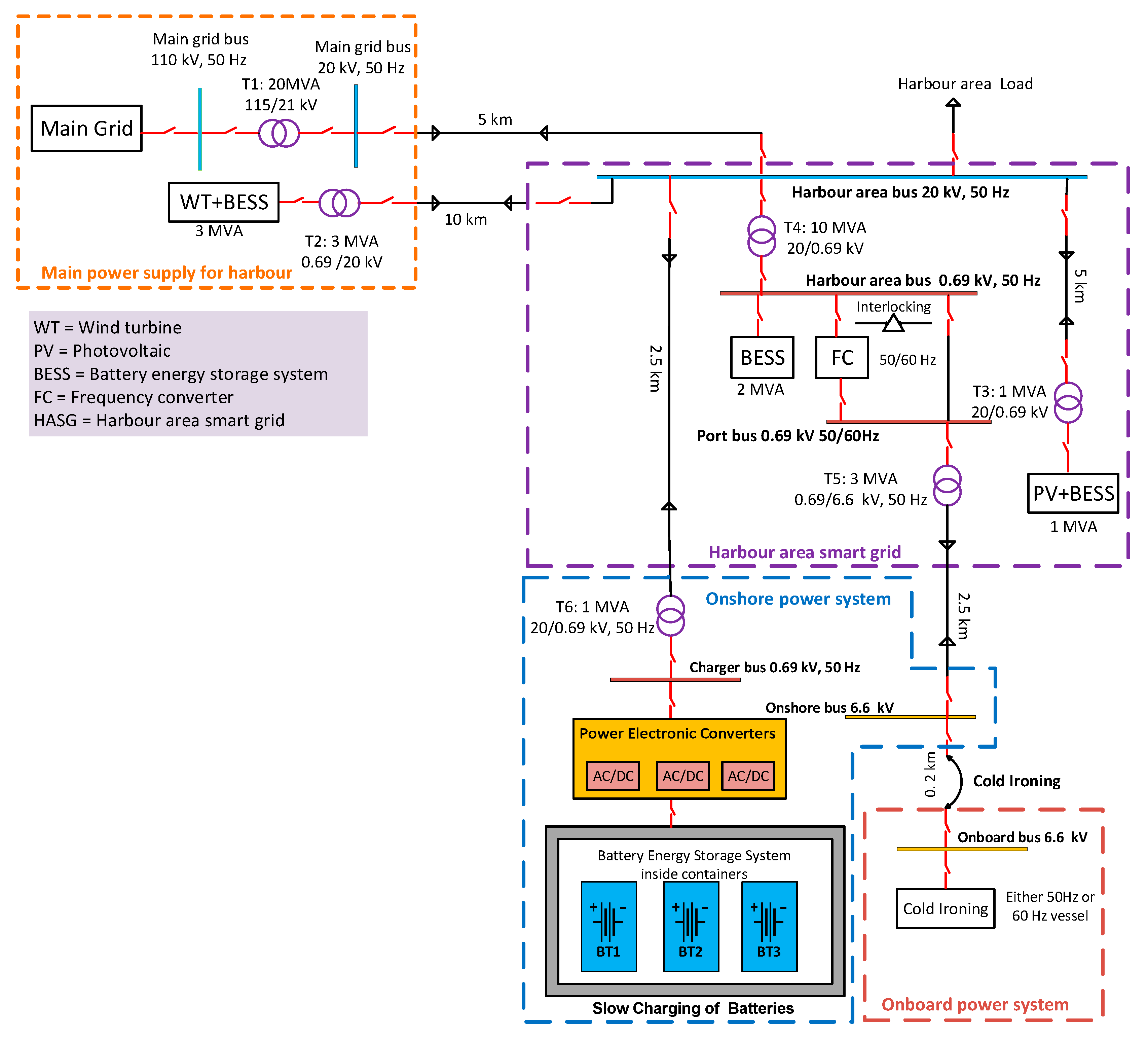
Configuration A is shown in Figure 2. Our example shows three batteries, each of 2 MWh capacity, inside three separate containers at shoreside in the harbour area. The cold-ironing load is supplied at 6.6 kV from the onshore bus, which is fed from the 0.69 kV port bus (in the HASG) through a step-up transformer (T5). The 20 kV harbour area bus (in the HASG) supplies power to the 0.69 kV charger bus for charging batteries through a step-down transformer (T6). Power electronic converters convert 0.69 kV AC to 0.69 kV DC (maximum) on shoreside for charging the batteries in the containers. Each battery (0.6 kV nominal voltage) is charged with a constant current of 290 A DC, creating a rise in battery voltage that depends on its state of charge (SOC); the maximum is 0.69 kV DC voltage at 100% SOC. The batteries are charged within 10 h, which is considered as normal or slow charging. The discharged batteries (from vessel) are exchanged with charged ones (from containers at shoreside) during cold-ironing. A main feature of this configuration is that the batteries may be charged in off-peak times at lower cost and less power requirement in comparison with other configurations.

3.2. Charging of Batteries Onboard—Fast Charging

In our examples of vessel-based charging methodologies, the vessel has three onboard fixed batteries, each of 2 MWh capacity. Each battery (0.6 kV nominal voltage) is charged with a constant current of 1450 A DC, producing a variable voltage (depending on the SOC of battery) to a maximum of 0.69 kV DC at 100% SOC. The batteries are charged within 2 h in a fast-charging mode during the vessel’s stay in harbour. We consider three configurations for fast charging, which vary in the power supply layout for cold-ironing and the battery-charging connections to the vessel. However, the charging methodology applied is the same in the following three configurations.

3.2.1. Charging of Batteries with DC Power from Shoreside and a Separately Connected AC Onshore Power Supply

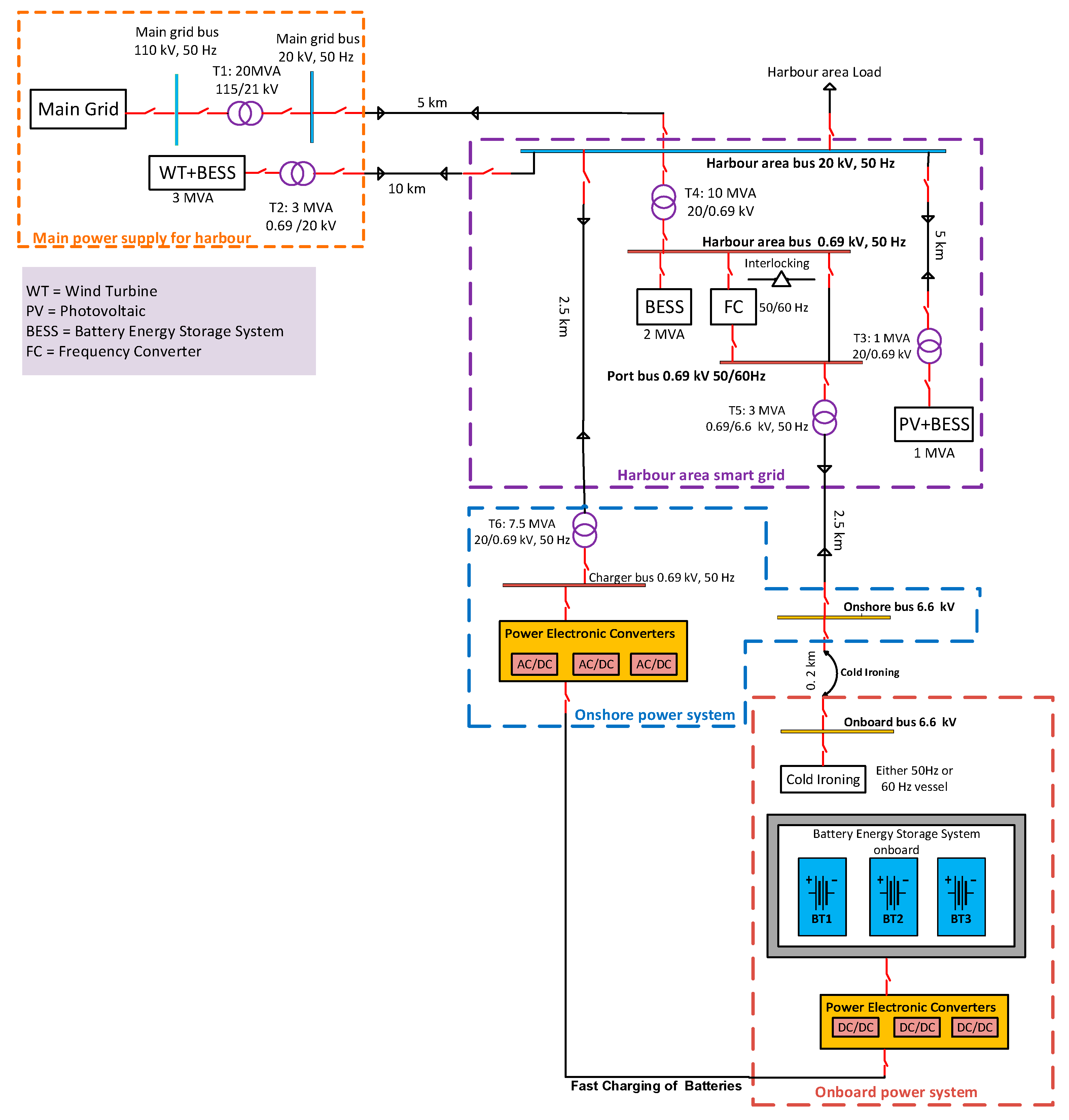
This is configuration B, where the AC onshore power supply and DC power for charging the batteries are supplied separately; these originate in the 0.69 kV port bus and 20 kV harbour area bus, respectively. Transformer (T6) converts power from the 20 kV harbour area bus to 0.69 kV AC, which power electronic converters transform to 0.69 kV DC (maximum) for charging batteries onboard, as shown in Figure 3. This configuration is distinguished by the availability of DC power supply at shoreside, which simplifies charging by eliminating the conversion of AC to DC power onboard. Thus, only DC–DC power electronic converters onboard the vessel are needed to control the charging voltage.

3.2.2. Charging of Batteries with a Shoreside AC Power Supply and a Separately Connected Onshore Power Supply

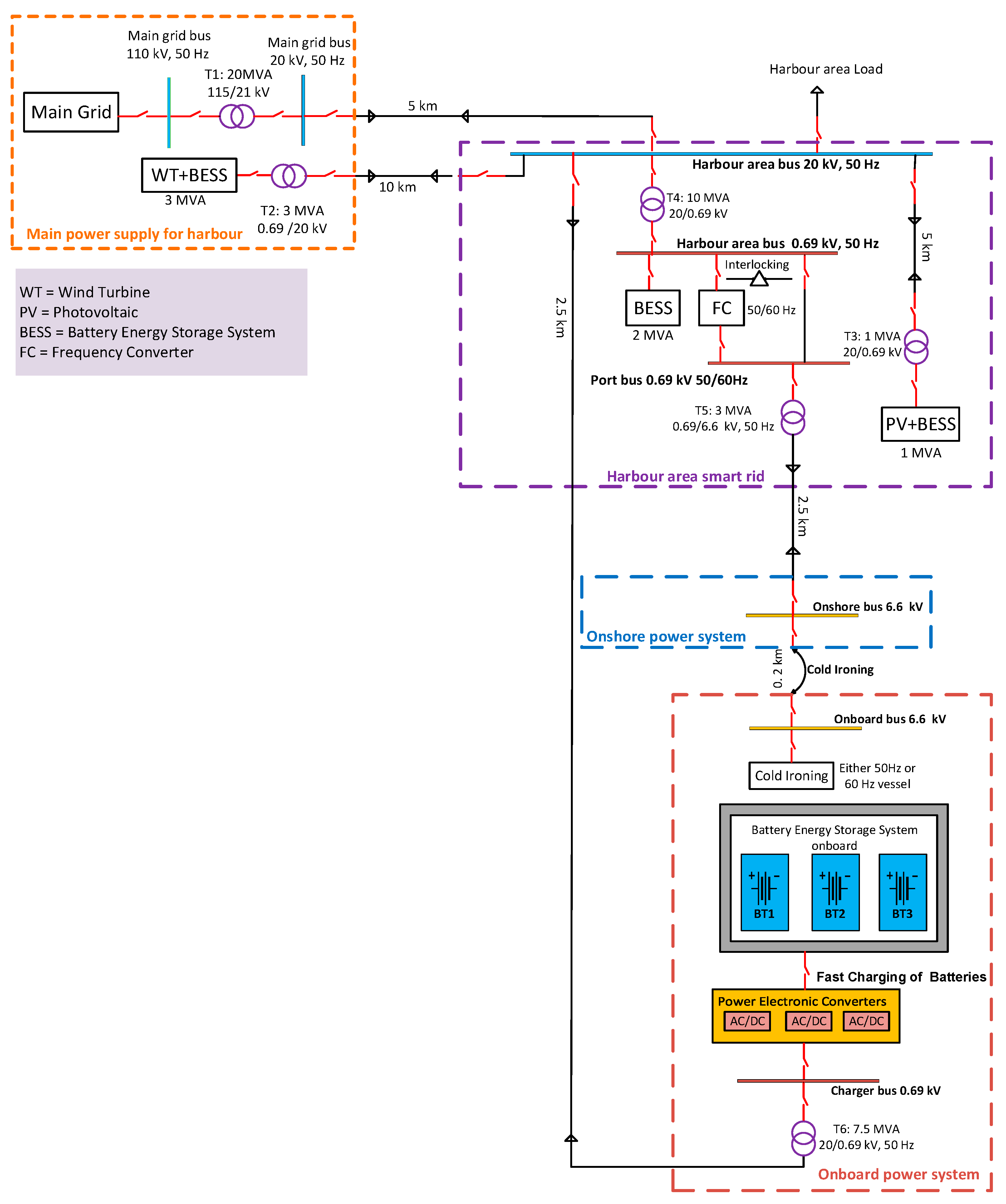
In configuration C (Figure 4), separate AC connections for the cold-ironing load and for charging the batteries are supplied power from the 0.69 kV port bus and the 20 kV harbour area bus, respectively. The 20 kV to 0.69 kV step-down transformer (T6) and the power electronic converters (0.69 kV AC to 0.69 kV DC maximum) for charging batteries are placed onboard. This configuration saves space at harbour areas because it does not require any charging-related equipment onshore, which is the key feature of the configuration.

3.2.3. Charging of Batteries and Onshore Power Supply with Same AC Power Supply

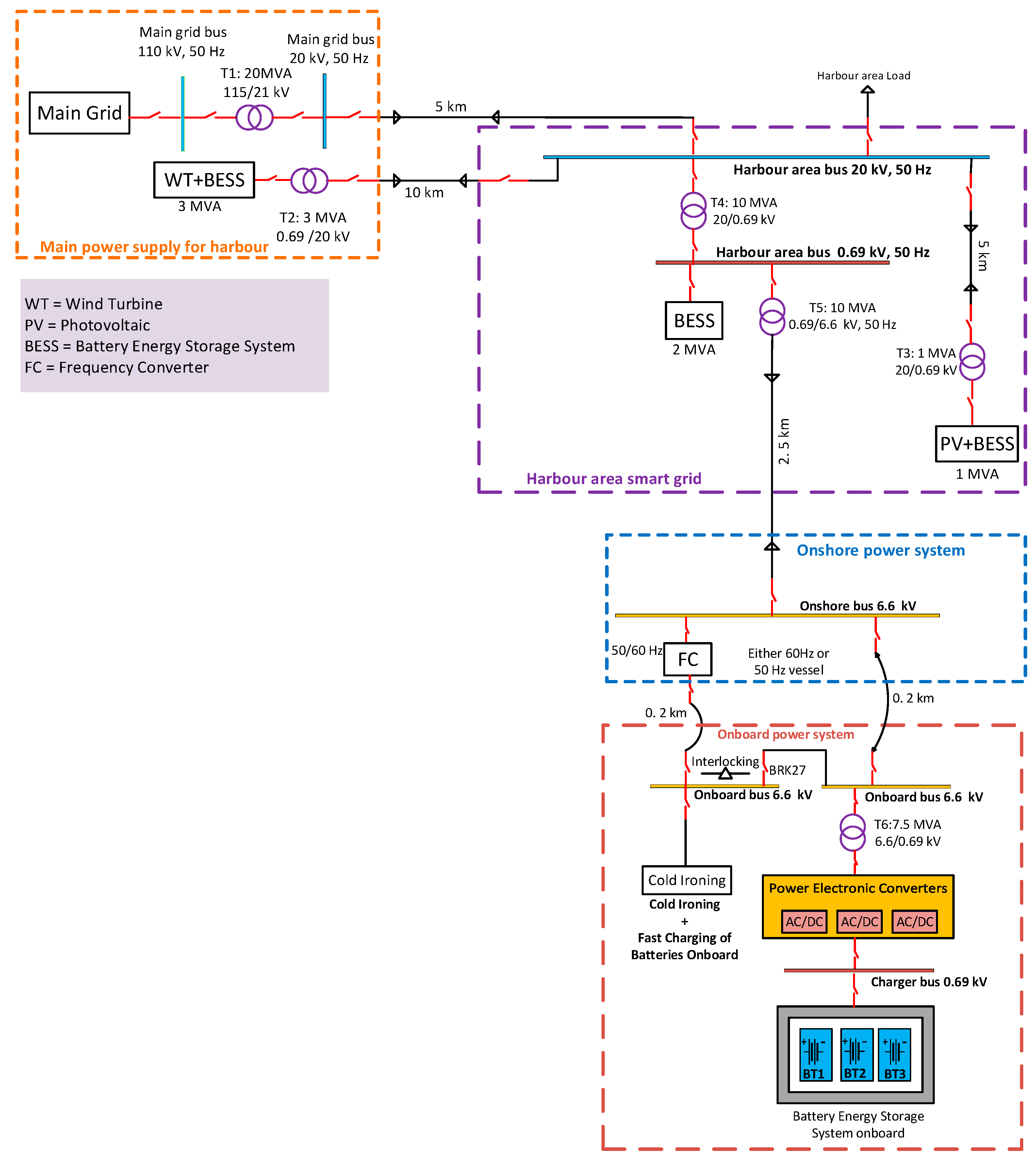
In configuration D (Figure 5), power is supplied by a single 6.6 kV connection (from the harbour area bus, 0.69 kV, 50 Hz) through a step-up transformer (T5, in the HASG) for both cold-ironing and onboard battery charging. Transformer (T6) steps down the onboard 6.6 kV to 0.69 kV AC, which is converted to 0.69 kV DC (maximum) for charging batteries.
The major difference between this charging configuration and the others is the location of the frequency converter. The harbour grid is initially assumed to be at 50 Hz (Figure 2), and the frequency converter shown has a power capacity that is only sufficient for the 60 Hz cold-ironing load; it is therefore not possible to include battery charging, using a single power supply connection coming through the frequency converter. The alternative of increasing the power capacity of the frequency converter to accommodate both types of load is not economically feasible because the frequency converter is one of the most expensive pieces of equipment in the harbour grid.
In configuration D, the frequency converter has been moved from a location connecting the harbour bus to the port bus (Figure 2) to a location between the onshore bus and the onboard vessel power system (Figure 5). Consequently, the port bus and its corresponding switchgear and protection devices are no longer required. The interlocking switch is placed to allow for either a 50 Hz or 60 Hz power supply for the cold-ironing load; however, this configuration can supply both cold-ironing load and battery-charging load with a single connection only if the harbour grid and the vessel power requirements are at the same power frequency, otherwise separate connections are required.

3.3. Combination of Onshore and Onboard Charging of Batteries—Slow and Fast Charging

Configuration E is a combination of container-based and vessel-based batteries (Figure 6). It consists of three batteries in containers at shoreside as well as three fixed batteries in the vessels, each of 0.6 kV nominal voltage and 2 MWh capacity. In this configuration, transformer (T6) steps down 20 kV to 0.69 kV AC, which power electronic converters convert to 0.69 kV DC (maximum) for charging the batteries in the shoreside containers. The shoreside batteries are charged with a constant current of 290 A DC to a maximum voltage of 0.69 kV DC at 100% SOC. The shoreside batteries are charged within 10 h, considered as slow charging; however, the fixed vessel batteries are then charged from shoreside batteries within 2 h in a fast-charging mode during the vessel’s stay at the harbour. The fast charging is with a constant current of 1450 A DC to a maximum of 0.69 kV DC at 100% SOC of the battery. This configuration may be characterised as a dual-charging mode that contains slow as well as fast segments.

3.4. Characteristics of Main Charging Scenarios

A comparison of the scenarios is presented in Table 1, using the classifications given in Figure 1.

3.5. Technical Challenges of Charging Scenarios

The first charging scenario (configuration A), which is container-based, requires at least the same number/capacity of replacement batteries in containers as the number/capacity onboard the vessel being serviced, as the discharged and charged batteries are exchanged during the vessel’s stay in harbour during cold-ironing. This increases the capital cost for batteries, requires additional equipment to move the battery containers, causes a higher system downtime from the connecting/disconnecting of batteries and increases the risk of mechanical failure. Moreover, this configuration needs shoreside space for charging the batteries inside containers.
The second charging scenario, onboard-based charging of batteries in configuration B, C or D requires higher power levels from shoreside than configurations A and E as a result of the fast charging of batteries directly from the grid supply. The power cables, power electronic converters, chargers, switchgear and protection equipment for a charging system in the vessel-based configurations will be of higher power capacity than configuration A, and thus require higher capital cost for the equipment and for advanced control and safety measures. Moreover, with the higher charging rate during fast charging, the danger of overcharging and overheating is increased. The transformer onboard the vessel in configurations C and D may pose the risk of fire, requiring an arrangement providing physical isolation. Configuration C requires two high-voltage plug connections, requiring personnel with a high-voltage certificate, and can thus incur additional costs compared with other configurations. Configuration D requires a different location for the frequency converter than in all the other configurations, otherwise a higher power capacity frequency converter with higher cost is needed.
The third charging scenario, configuration E, has both slow- and fast-charging characteristics, and requires two types of power supply equipment (such as power electronic converters, power cables, chargers, switchgear and protection devices) with low and high power ratings, respectively. Thus, on one hand, configuration E is expensive, and in addition, it produces higher power losses due to dual power conversion stages. However, configuration E is a suitable design when considering a hybrid microgrid consisting of AC and DC buses inside the HASG, that is, a harbour having the potential of using renewable and sustainable energy sources, and where there is availability of space for the required infrastructure.

4. Simulation Study

In order to verify the technical feasibility of these configurations, a simulation study was carried out. All the configurations were modelled with PSCAD software, and the components were dimensioned to provide reasonable results. Both slow- and fast-charging scenarios were used for simulations (e.g., the container-based charging of batteries (configuration A) and the vessel-based charging of batteries (configuration D)). A time-varying dynamic load of 2 MW maximum power was considered for cold-ironing in both the slow- and fast-charging simulation models. The nominal charging load including power losses in configuration A was 0.7 MW for a charging rate of 0.1 C, whereas in configuration D, the load was 4.5 MW for a rate of 0.5 C.
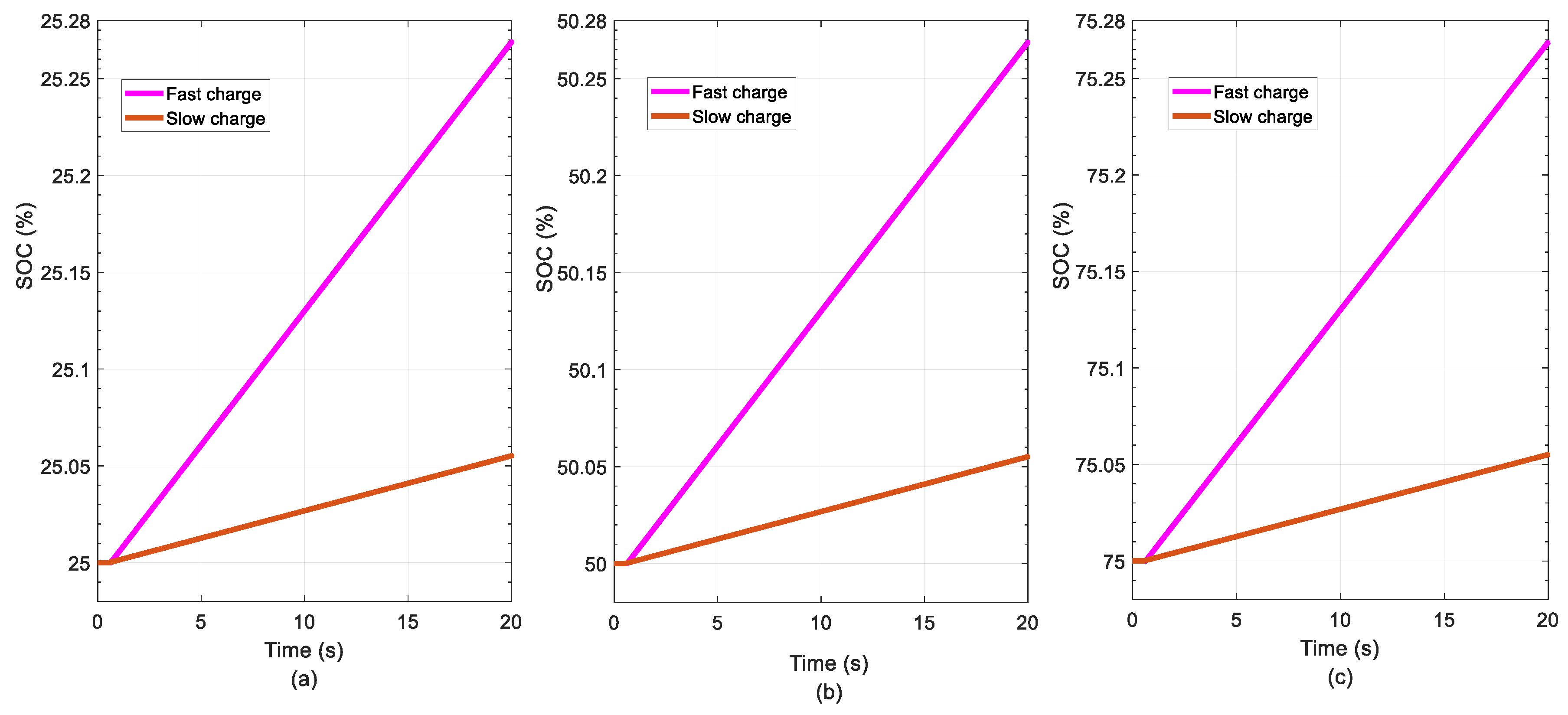
Table 2 and Table 3 present the simulation results of container-based and vessel-based charging of batteries, respectively. The onshore bus voltage is maintained within specified limits (a maximum voltage drop of 3.5%, according to the HVSC standards) during maximum cold-ironing load. The battery voltage at a specific SOC and battery current is also maintained within the required nominal values. The frequency of the onshore power supply is constant, and the total harmonic distortion (THD) of the charger current and voltage are within limits. The rate of change of the SOC for slow and fast charging is indicated in Figure 7, which is based on the sampled values of 20 seconds while considering the initial SOC at 25, 50 and 75%. This shows that these chargers are capable of charging the batteries in the assumed time frames of 10 and 2 h, respectively. Moreover, in Figure 7, the fast-charging rate is five times higher than the slow rate.
The simulation results show that the performance for slow and fast charging (configurations A and D, respectively) is satisfactory, and these configurations can be implemented practically. It is observed that maintaining all bus voltages in the slow-charging model (configuration A) is achievable as a result of the separate connections for battery charging and for the onshore supply of the cold-ironing load.
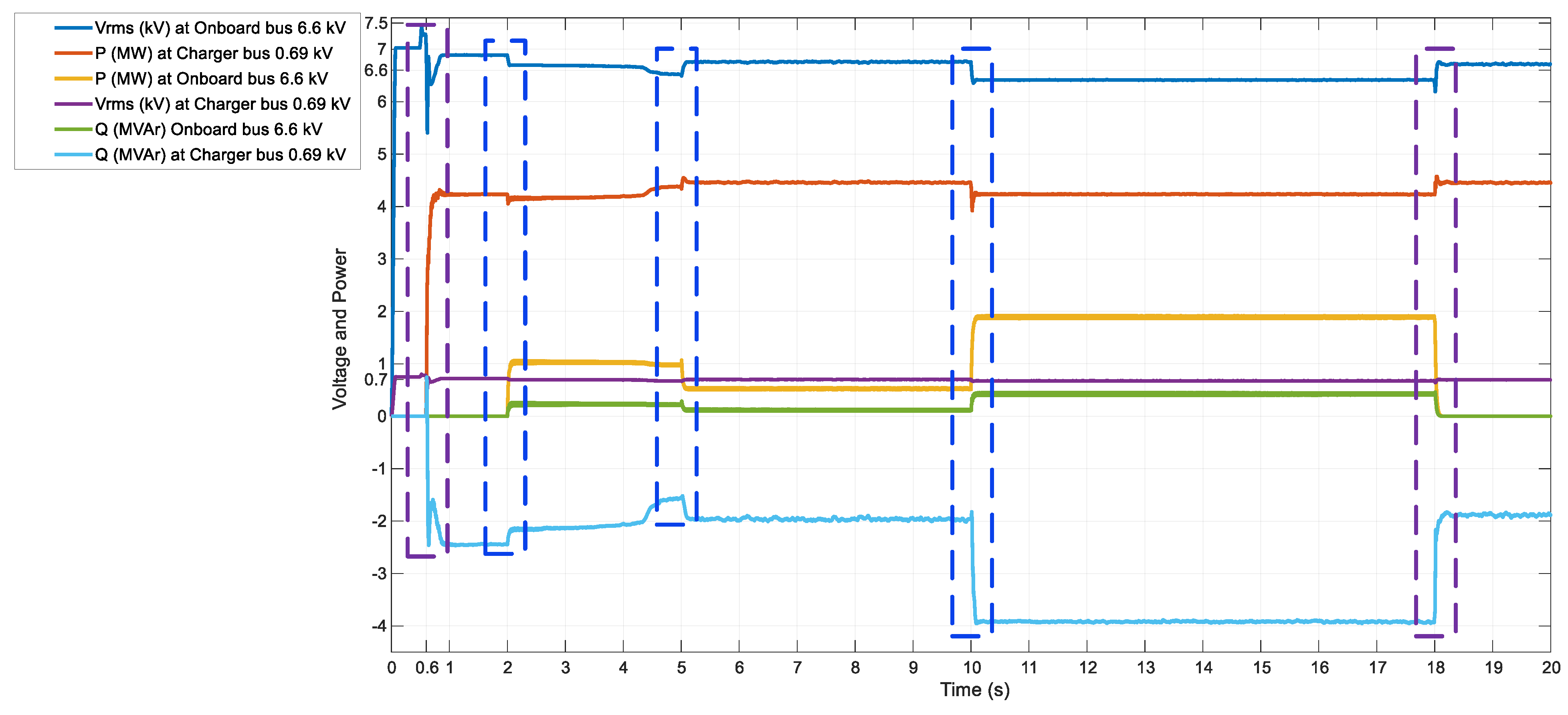
However, in the fast-charging model (see Figure 8 for a simulation of configuration D), it is challenging to maintain all bus voltages, especially for the onboard and charging buses. The dynamic changes of the voltage and power in the onboard and charger buses, resulting from time-varying cold-ironing loads together with charging, are highlighted by the dotted lines. At t = 0.6 s, the fast charger load is connected, and momentary rapid changes in voltages occur due to switching transients. To observe the dynamics, a time-varying cold-ironing load is taken into account by assuming power capacity of certain ports. The cold-ironing load is connected initially with a power rating of (1 MW + j0.15 MVAr), decreased to (0.5 MW + j0.075 MVAr) at t = 5 s, increased to a maximum load (2 MW + j0.3 MVAr) at t = 10 s and finally disconnected at t = 18 s. This shows that reactive power flow in the charger bus depends on the onboard bus voltage; this flow decreases along with a decrease in onboard bus voltage due to an increase in the cold-ironing load. Simulation shows that the voltage on the onboard and charger buses also drops during high power conversion (for charging) alone. There are several options for maintaining the voltage, but an on-load tap changer on transformer T1 is considered a suitable and economic solution and it is used in this study to maintain the voltage whenever the downstream voltage at the onshore and onboard buses varies due to the dynamic load.

5. Discussion

The findings reveal that BESSs can play a significant role in the onboard and onshore marine sectors as a result of several beneficial features. The application of BESSs onboard a vessel can increase the operational life of diesel generators and reduce their maintenance cost. It can also improve the dynamic response to varying propulsion loads by providing peak load power instantly and store energy during low load power requirements. As a part of a shipboard power system, a BESS can also save fossil fuels and increase energy efficiency in modern hybrid vessels. At the same time, the application of a BESS in a modern HASG can enable the use of renewable energy sources at shoreside in harbour areas and support a weak grid in the case of power unbalance, stability and reliability issues. A BESS in harbour areas can also be used as an energy management system to optimally and efficiently control energy flows between the BESS and the main grid for the purpose of energy arbitrage and peak shaving. Moreover, in the islanded mode of operation of an HASG, load shedding may not be a viable option because of the importance of keeping to the schedule of a vessel’s stay at a seaport. Therefore, a BESS as a master unit can support the uninterrupted operation of an HASG.
Onboard power electronic converters (configurations C and D) that operate on both 50 and 60 Hz would enable a ship to visit any harbour grid with either of these two power supply frequencies. The two charging configurations A and D are suitable for vessels operating entirely on a BESS, or with a BESS as part of a hybrid energy system, and their performance has been validated with PSCAD simulations.
The slow-charging configuration is a feasible choice for a harbour having a low power capacity and ships with less space available onboard, and the fast-charging configuration could be preferred for a harbour with high power capacity or low docking space. However, the slow charging could be preferred because at faster charging rates, more power is lost as heat and therefore cannot be recoverable as electricity later. In future, a configuration that combines slow- and fast-charging methodologies (configuration E) would be a useful option when considering a hybrid microgrid at a harbour. It can be a costly investment, however, it has the beneficial features of both slow and fast charging. This option is suitable for harbours with a low power capacity and for vessels requiring fast charging onboard, where the availability of space onboard and on shoreside is not a major problem.

6. Conclusions and Outlook

This study was conducted to explore alternative configurations for battery charging in harbours for modern vessels employing BESSs as a key component. Based on a literature review, it is concluded that this is the first attempt to systematically investigate these alternatives. Several configurations for battery charging in harbours were investigated, and each configuration has its key merits and limitations from the perspectives of economic and technical feasibility, and of space availability on shore and ship. The appropriate charging configuration can be decided based on the available infrastructure at a harbour and the demands of ships.
Two charging scenarios were further developed in detail, one from the slow-charging and the other from the fast-charging category; their performance was validated by simulation studies. These two categories are applicable to both electric and hybrid vessels. The present findings can be the basis for ships’ owners creating suitable business models and for port administrators promoting the application of BESSs in the marine sector.
Further research is required on hybrid microgrids for harbour areas. The hybrid microgrid can facilitate the combination of slow- and fast-charging configurations while exploiting the advantages of both types. Finally, the future work of the authors is in expanding the harbour grid system on a modular basis; advanced control techniques can be applied to operate these modules in parallel, adapted to the specific power requirements of different ships visiting the harbour area simultaneously. The other interesting future work is to investigate round-trip efficiency of battery energy storage systems which determines power lost as heat at certain charging rates.

Author Contributions

Conceptualization, J.K.; Formal analysis, A.A.M., L.K., K.K. and O.P.; Investigation, J.K. and L.K.; Methodology, J.K. and A.A.M.; Software, J.K. and A.A.M.; Supervision, K.K.; Validation, J.K. and A.A.M.; Visualization, J.K., L.K., K.K. and O.P.; Writing—original draft, J.K.; A.A.M.; Writing—review & editing, L.K., K.K. and O.P.

Funding

This work was carried out in FESSMI research project with financial support provided by the European Regional Development Fund (ERDF) through the Finnish Funding Agency for Technology and Innovation (Tekes) with grant No. 3345/31/2015. The corresponding author is also thankful to the University of Vaasa for the research grant to carry out this work.

Acknowledgments

The authors are also thankful to Bjornar Skogseth (Wärtsilä), and Ari Pätsi (VEO) for their valuable comments about the core content of the paper.

Conflicts of Interest

The authors declare no conflict of interest.

Abbreviations

ACAlternating Current
AESAll-Electric Ship
BESSBattery Energy Storage System
CC/CVConstant Current–Constant Voltage
DCDirect Current
EUEuropean Union
FCFrequency Converter
HVSCHigh-Voltage Shore Connection
HASGHarbour Area Smart Grid
IECInternational Electrotechnical Commission
IEEEInstitute of Electrical and Electronics Engineers
IMOInternational Maritime Organization
ISOInternational Organization for Standardization
PSCADPower Systems Computer-Aided Design
PVPhotovoltaic
SOCState of Charge
THDTotal Harmonic Distortion
WTWind Turbine

References

  1. International Maritime Organization. Third IMO GHG Study 2014 Executive Summary and Final Report; International Maritime Organization: London, UK, 2015. [Google Scholar]
  2. European Commission. Roadmap to a Single European Transport Area–Towards a Competitive and Resource Efficient Transport System; Publications Office of the European Union: Luxembourg, 2011; ISBN 9789279182709. [Google Scholar]
  3. Winnes, H.; Styhre, L.; Fridell, E. Reducing GHG emissions from ships in port areas. Res. Transp. Bus. Manag. 2015, 17, 73–82. [Google Scholar] [CrossRef] [Green Version]
  4. Al-Falahi, M.D.; Nimma, K.S.; Jayasinghe, S.D.; Enshaei, H.; Guerrero, J.M. Power management optimization of hybrid power systems in electric ferries. Energy Convers. Manag. 2018, 172, 50–66. [Google Scholar] [CrossRef] [Green Version]
  5. Kanellos, F.D.; Anvari-Moghaddam, A.; Guerrero, J.M. A cost-effective and emission-aware power management system for ships with integrated full electric propulsion. Electr. Power Syst. Res. 2017, 150, 63–75. [Google Scholar] [CrossRef] [Green Version]
  6. Sciberras, E.A.; Zahawi, B.; Atkinson, D.J. Electrical characteristics of cold ironing energy supply for berthed ships. Transp. Res. Part D Transp. Environ. 2015, 39, 31–43. [Google Scholar] [CrossRef] [Green Version]
  7. García-Olivares, A.; Sole, J.; Osychenko, O. Transportation in a 100% renewable energy system. Energy Convers. Manag. 2018, 158, 266–285. [Google Scholar] [CrossRef]
  8. Li, S.; Mojdehi, M.N.; Liu, N.; Ghosh, P. Transportation electrification: From vehicle to grid integration. In Proceedings of the 2016 Clemson University Power Systems Conference (PSC), Clemson, SC, USA, 8–11 March 2016; pp. 1–6. [Google Scholar]
  9. Directive 2005/33/EC of the European Parliament and of the Council. Off. J. Eur. Union 2005, L 191, 59–69.
  10. Kumar, J.; Kumpulainen, L.; Kauhaniemi, K. Technical design aspects of harbour area grid for shore to ship power: State of the art and future solutions. Int. J. Electr. Power Energy Syst. 2019, 104, 840–852. [Google Scholar] [CrossRef]
  11. Ling-Chin, J.; Roskilly, A.P. A comparative life cycle assessment of marine power systems. Energy Convers. Manag. 2016, 127, 477–493. [Google Scholar] [CrossRef] [Green Version]
  12. Skjong, E.; Rodskar, E.; Molinas, M.; Johansen, T.A.; Cunningham, J. The Marine Vessel’s Electrical Power System: From its Birth to Present Day. Proc. IEEE 2015, 103, 2410–2424. [Google Scholar] [CrossRef]
  13. Geertsma, R.; Negenborn, R.; Visser, K.; Hopman, J. Design and control of hybrid power and propulsion systems for smart ships: A review of developments. Appl. Energy 2017, 194, 30–54. [Google Scholar] [CrossRef]
  14. Sakalis, G.N.; Tzortzis, G.J.; Frangopoulos, C.A. Intertemporal Static and Dynamic Optimization of Synthesis, Design, and Operation of Integrated Energy Systems of Ships. Energies 2019, 12, 893. [Google Scholar] [CrossRef]
  15. Balsamo, F.; Lauria, D.; Mottola, F. Design and Control of Coupled Inductor DC–DC Converters for MVDC Ship Power Systems. Energies 2019, 12, 751. [Google Scholar] [CrossRef]
  16. Mutarraf, M.; Terriche, Y.; Niazi, K.; Vasquez, J.; Guerrero, J. Energy Storage Systems for Shipboard Microgrids—A Review. Energies 2018, 11, 3492. [Google Scholar] [CrossRef]
  17. Al-Falahi, M.D.A.; Tarasiuk, T.; Jayasinghe, S.G.; Jin, Z.; Enshaei, H.; Guerrero, J.M. AC Ship Microgrids: Control and Power Management Optimization. Energies 2018, 11, 1458. [Google Scholar] [CrossRef]
  18. Jin, Z.; Sulligoi, G.; Cuzner, R.; Meng, L.; Vasquez, J.C.; Guerrero, J.M. Next-Generation Shipboard DC Power System: Introducing Smart Grid and dc Microgrid Technologies into Maritime Electrical Netowrks. IEEE Electrif. Mag. 2016, 4, 45–57. [Google Scholar] [CrossRef]
  19. Vicenzutti, A.; Bosich, D.; Giadrossi, G.; Sulligoi, G. The Role of Voltage Controls in Modern All-Electric Ships: Toward the all electric ship. IEEE Electrif. Mag. 2015, 3, 49–65. [Google Scholar] [CrossRef]
  20. Hansen, J.F.; Wendt, F. History and State of the Art in Commercial Electric Ship Propulsion, Integrated Power Systems, and Future Trends. Proc. IEEE 2015, 103, 2229–2242. [Google Scholar] [CrossRef]
  21. Vicenzutti, A.; Menis, R.; Sulligoi, G. Dependable design of all electric ships integrated power system: New design process. In Proceedings of the 2016 International Conference on Electrical Systems for Aircraft, Railway, Ship Propulsion and Road Vehicles & International Transportation Electrification Conference (ESARS-ITEC), Toulouse, France, 2–4 November 2016; pp. 1–6. [Google Scholar]
  22. Hebner, R.E.; Uriarte, F.M.; Kwasinski, A.; Gattozzi, A.L.; Estes, H.B.; Anwar, A.; Cairoli, P.; Dougal, R.A.; Feng, X.; Chou, H.M.; et al. Technical cross-fertilization between terrestrial microgrids and ship power systems. J. Mod. Power Syst. Clean Energy 2016, 4, 161–179. [Google Scholar] [CrossRef]
  23. Peralta, C.O.; Vieira, G.T.T.; Meunier, S.; Vale, R.J.; Salles, M.B.C.; Carmo, B.S. Evaluation of the CO2 Emissions Reduction Potential of Li-ion Batteries in Ship Power Systems. Energies 2019, 12, 375. [Google Scholar] [CrossRef]
  24. Sørensen, A.J.; Skjetne, R.; Bo, T.; Miyazaki, M.R.; Johansen, T.A.; Utne, I.B.; Pedersen, E. Toward Safer, Smarter, and Greener Ships: Using Hybrid Marine Power Plants. IEEE Electrif. Mag. 2017, 5, 68–73. [Google Scholar] [CrossRef] [Green Version]
  25. Dedes, E.K.; Hudson, D.A.; Turnock, S.R. Assessing the potential of hybrid energy technology to reduce exhaust emissions from global shipping. Energy Policy 2012, 40, 204–218. [Google Scholar] [CrossRef]
  26. Misyris, G.S.; Marinopoulos, A.; Doukas, D.I.; Tengnér, T.; Labridis, D.P. On battery state estimation algorithms for electric ship applications. Electr. Power Syst. Res. 2017, 151, 115–124. [Google Scholar] [CrossRef]
  27. Hoque, M.M.; Hannan, M.A.; Mohamed, A. Charging and discharging model of lithium-ion battery for charge equalization control using particle swarm optimization algorithm. J. Renew. Sustain. Energy 2016, 8, 065701. [Google Scholar] [CrossRef]
  28. Divya, K.; Østergaard, J. Battery energy storage technology for power systems—An overview. Electr. Power Syst. Res. 2009, 79, 511–520. [Google Scholar] [CrossRef]
  29. Palizban, O.; Kauhaniemi, K. Energy storage systems in modern grids—Matrix of technologies and applications. J. Energy Storage 2016, 6, 248–259. [Google Scholar] [CrossRef]
  30. Panday, A.; Bansal, H.O. Energy management strategy for hybrid electric vehicles using genetic algorithm. J. Renew. Sustain. Energy 2016, 8, 015701. [Google Scholar] [CrossRef]
  31. Yanhui, Z.; Wenji, S.; Shili, L.; Jie, L.; Ziping, F. A critical review on state of charge of batteries. J. Renew. Sustain. Energy 2013, 5, 021403. [Google Scholar] [CrossRef]
  32. Hakimi, S.M.; Moghaddas-Tafreshi, S.M. Effect of plug-in hybrid electric vehicles charging/discharging management on planning of smart microgrid. J. Renew. Sustain. Energy 2012, 4, 063144. [Google Scholar] [CrossRef]
  33. Kumar, J.; Palizban, O.; Kauhaniemi, K. Designing and analysis of innovative solutions for harbour area smart grid. In Proceedings of the 2017 IEEE Manchester PowerTech, Manchester, UK, 18–22 June 2017; pp. 1–6. [Google Scholar]
  34. Lamberti, T.; Sorce, A.; Di Fresco, L.; Barberis, S. Smart port: Exploiting renewable energy and storage potential of moored boats. In Proceedings of the OCEANS 2015—Genova, Genoa, Italy, 18–21 May 2015; pp. 1–3. [Google Scholar]
  35. Lee, K.-J.; Shin, D.; Yoo, D.-W.; Choi, H.-K.; Kim, H.-J. Hybrid photovoltaic/diesel green ship operating in standalone and grid-connected mode—Experimental investigation. Energy 2013, 49, 475–483. [Google Scholar] [CrossRef]
  36. Alnes, O.; Eriksen, S.; Vartdal, B.-J. Battery-Powered Ships: A Class Society Perspective. IEEE Electrif. Mag. 2017, 5, 10–21. [Google Scholar] [CrossRef]
  37. Dale, S.J.; Hebner, R.E.; Sulligoi, G. Electric Ship Technologies. Proc. IEEE 2015, 103, 2225–2228. [Google Scholar] [CrossRef]
  38. Guidi, G.; Jenset, F.; Sorfonn, I.; Suul, J.A. Wireless Charging for Ships: High-Power Inductive Charging for Battery Electric and Plug-In Hybrid Vessels. IEEE Electrif. Mag. 2017, 5, 22–32. [Google Scholar] [CrossRef]
  39. Doerry, N.; Amy, J.; Krolick, C. History and the Status of Electric Ship Propulsion, Integrated Power Systems, and Future Trends in the U.S. Navy. Proc. IEEE 2015, 103, 2243–2251. [Google Scholar] [CrossRef]
  40. Ling-Chin, J.; Roskilly, A. Investigating a conventional and retrofit power plant on-board a Roll-on/Roll-off cargo ship from a sustainability perspective –A life cycle assessment case study. Energy Convers. Manag. 2016, 117, 305–318. [Google Scholar] [CrossRef]
  41. Sciberras, E.A.; Zahawi, B.; Atkinson, D.J. Reducing shipboard emissions—Assessment of the role of electrical technologies. Transp. Res. Part D Transp. Environ. 2017, 51, 227–239. [Google Scholar] [CrossRef]
  42. IEC/ISO/IEEE 80005-1 Utility Connections Port-Part 1: HIgh Voltage Shore Connection (HVSC) Systems-General Requirements; IEC/ISO/IEEE International Standard; IEC: Geneva, Switzerland; ISO: Geneva, Switzerland; IEEE: New York, NY, USA, 2012.
  43. Coppola, T.; Fantauzzi, M.; Lauria, D.; Pisani, C.; Quaranta, F. A sustainable electrical interface to mitigate emissions due to power supply in ports. Renew. Sustain. Energy Rev. 2016, 54, 816–823. [Google Scholar] [CrossRef] [Green Version]
  44. Skjong, E.; Johansen, T.A.; Molinas, M.; Sorensen, A.J. Approaches to Economic Energy Management in Diesel–Electric Marine Vessels. IEEE Trans. Transp. Electrif. 2017, 3, 22–35. [Google Scholar] [CrossRef]
  45. Bulletin, T. Charging valve regulated lead acid batteries. J. Power Sources 1995, 53, 143–147. [Google Scholar]
  46. De Breucker, S. Impact of DC-DC Converters on Li-ion Batteries; KU Leuven: Leuven, Belgium, 2012; ISBN 9789460182761. [Google Scholar]
  47. Vo, T.T.; Shen, W.; Kapoor, A. Experimental comparison of charging algorithms for a lithium-ion battery. In Proceedings of the 2012 10th International Power & Energy Conference (IPEC), Ho Chi Minh City, Vietnam, 12–14 December 2012; pp. 207–212. [Google Scholar]
  48. Dearborn, S. Charging Li-ion Batteries for Maximum Run Times. Power Electron. Technol. 2005, 40–49. [Google Scholar]
  49. IEC PAS 80005-3 Utility Connections in Port—Part 3: Low Voltage Shore Connection (LVSC) Systems—General Requirements; IEC/ISO Publicaly Available Specification Pre-Standard: Geneva, Switzerland, 2014.
  50. Wei, Z.; Zhao, J.; Xiong, R.; Dong, G.; Pou, J.; Tseng, K.J. Online estimation of power capacity with noise effect attenuation for lithium-ion battery. IEEE Trans. Ind. Electron. 2019, 66, 5724–5735. [Google Scholar] [CrossRef]
  51. Wei, Z.; Zhao, J.; Ji, D.; Tseng, K.J. A multi-timescale estimator for battery state of charge and capacity dual estimation based on an online identified model. Appl. Energy 2017, 204, 1264–1274. [Google Scholar] [CrossRef]
  52. Wei, Z.; Meng, S.; Xiong, B.; Ji, D.; Tseng, K.J. Enhanced online model identification and state of charge estimation for lithium-ion battery with a FBCRLS based observer. Appl. Energy 2016, 181, 332–341. [Google Scholar] [CrossRef]
Figure 1. Classification of charging scenarios: onshore (slow), onboard (fast) and a hybrid (slow and fast).
Energies 12 02354 g001
Figure 2. Configuration A: Container-based charging of batteries and cold-ironing.
Energies 12 02354 g002
Figure 3. Configuration B: Fast charging of onboard batteries with a DC power supply from shoreside and cold-ironing with a separate connection.
Energies 12 02354 g003
Figure 4. Configuration C: Fast charging of onboard batteries with an AC power supply from shoreside and onshore power is with a separate connection.
Energies 12 02354 g004
Figure 5. Configuration D: Fast charging of onboard batteries and cold-ironing from the same onshore AC power supply.
Energies 12 02354 g005
Figure 6. Configuration E: Combination of the container- and vessel-based charging of batteries along with cold-ironing.
Energies 12 02354 g006
Figure 7. Rate of change of SOC of batteries in configurations A and D, (a) When BESS is at 25% SOC (b) When BESS is at 50% SOC (c) When BESS is at 75% SOC.
Energies 12 02354 g007
Figure 8. Voltage and power at onboard and charger buses in configuration D.
Energies 12 02354 g008
Table 1. Attributes of the charging configurations.
Charging ScenariosAdvantagesDisadvantages
Charging of batteries onshore—slow charging
Configuration A
Easy and flexible to implement.
Low power required at shoreside with the slow/normal charging of batteries at shoreside as compared to all other configurations.
Power cables, power electronic converters, chargers, switchgear and protection equipment for charging system will be of lower power capacity than the other configurations.
Simple chargers are required and should not result in battery overheating.
Equipment and personnel required to move the battery containers.
Higher capital cost because every harbour should have a sufficient number/capacity of batteries in containers to replace those in vessels being serviced.
No space saving at the harbour area.
Higher system downtime due to connecting/disconnecting of batteries; mechanical failure can occur.
Charging of batteries onboard—fast charging
Configurations
B, C, D
Lower capital cost for batteries than configurations A and E: batteries remain onboard, with no exchange of discharged/charged batteries.
Less space is required on shoreside as compared to configurations A and E.
No equipment required to move battery containers as compared to configuration A.
Higher power required on shoreside as compared to configurations A and E.
Power cables, converters, chargers, switchgear and protection equipment for charging system will be of higher power capacity than for configurations A or E.
As the charging rate increases, the danger of overcharging and overheating also increases.
Higher energy density batteries and compact onboard chargers are needed.
More space and weight onboard the vessel are required in configurations C and D for the extra transformer on the vessel for charging the batteries.
Transformer onboard poses a risk of fire so that physical isolation may be required.
Combination of onshore and onboard charging of batteries—slow and fast charging
Configuration E
Lower power required at shoreside than configurations B, C and D. Power cables, power electronic converters, chargers, switchgear and protection equipment for charging system on shoreside will be of lower power capacity than for configurations B, C and D.
No equipment required to move battery containers as compared to configuration A.
This configuration may be suitable if a hybrid microgrid with AC and DC buses is designed.
Configuration E has almost the same disadvantages as configuration A, except there is no need for equipment to move battery containers and no risk from connecting/disconnecting of batteries.
Configuration E has more or less the same disadvantages as those of fast charging configurations (B, C and D) excluding the need for transformer onboard.
Table 2. Simulation results of Configuration A: Container-based charging of batteries and cold-ironing.
EntitiesNominal ValuesMeasured Values
Main Grid Voltage110 kV110 kV (Constant)
Main Grid Voltage20 kV20.88 kV (Maximum)
Harbour Bus Voltage20 kV21.15 kV (Maximum)
Harbour Bus Voltage0.69 kV0.72–0.74 kV
Port Bus Voltage0.69 kV0.71–0.74 kV
Onshore Bus Voltage6.6 kV6.4–7.1 kV
Battery Voltage 0.6 kV0.678 kV (at 95% SOC)
Battery Current290 A290 A
Onshore Bus Frequency50 Hz50 Hz
THD for Charger Current (%)5 % (Maximum Allowed)5 %
THD for Charger Voltage (%)5 % (Maximum Allowed)1.19 %
Table 3. Simulation results of Configuration D: Fast charging of onboard batteries and cold-ironing from the same onshore AC power supply.
EntitiesNominal ValuesMeasured Values
Main Grid Voltage110 kV110 kV (Constant)
Main Grid Voltage20 kV21.9 kV (Maximum)
Harbour Bus Voltage20 kV21.7 kV (Maximum)
Harbour Bus Voltage0.69 kV0.71–0.72 kV
Port Bus Voltage0.69 kV0.66–0.69 kV
Onshore Bus Voltage6.6 kV6.45–6.75 kV
Battery Voltage 0.6 kV0.7 kV (at 95% SOC)
Battery current1450 A1450 A
Onshore Bus Frequency50 Hz50 Hz
THD for charger current (%)5 % (Maximum Allowed)1.386 %
THD for charger voltage (%)5 % (Maximum Allowed)1.52 %