Predictive-Fixed Switching Current Control Strategy Applied to Six-Phase Induction Machine
by
 , , , ,
Osvaldo Gonzalez
1,* ,
,
Magno Ayala
1 ,
,
Jesus Doval-Gandoy
2 ,
,
Jorge Rodas
1 ,
,
Raul Gregor
1 and 
Marco Rivera
3
1
Laboratory of Power and Control Systems (LSPyC), Facultad de Ingeniería, Universidad Nacional de Asunción, Luque 2060, Paraguay
2
Applied Power Electronics Technology Research Group (APET), Universidad de Vigo, 363310 Vigo, Spain
3
Laboratory of Energy Conversion and Power Electronics, Universidad de Talca, 3340000 Curicó, Chile
*
Author to whom correspondence should be addressed.
Energies 2019, 12(12), 2294; https://doi.org/10.3390/en12122294
Submission received: 27 April 2019
/
Revised: 20 May 2019
/
Accepted: 30 May 2019
/
Published: 15 June 2019
(This article belongs to the Special Issue Control of Multiphase Machines and Drives)
Abstract
:In applications such as multiphase motor drives, classical predictive control strategies are characterized by a variable switching frequency which adds high harmonic content and ripple in the stator currents. This paper proposes a model predictive current control adding a modulation stage based on a switching pattern with the aim of generating a fixed switching frequency. Hence, the proposed controller takes into account the prediction of the two adjacent active vectors and null vector in the (-) frame defined by space vector modulation in order to reduce the (x-y) currents according to a defined cost function at each sampling period. Both simulation and experimental tests for a six-phase induction motor drive are provided and compared to the classical predictive control to validate the feasibility of the proposed control strategy.
1. Introduction
In recent years, multiphase induction machines (IMs) have been considered to be such a viable alternative in comparison to three-phase machines due to their fault tolerance capabilities with no extra hardware, lower torque ripple and better power splitter per phase which result very attractive to the research community for various industrial applications where a high-performance control strategy, as well as, reliability are required [1]. Presently, some applications of multiphase IMs that are being investigated include wind energy generation system [2], hybrid electric vehicles (EV) [3] and ship propulsion. In the applications mentioned above, multiphase IMs can be used under different conditions, such as healthy and post-fault operations [4,5]. From the point of view of control, the most common control strategy to regulate multiphase IMs is the field-oriented control (FOC), which is constituted by an inner current control loop, to obtain the references voltages, and an outer speed control loop for speed regulation [6]. However, several new control approaches have been carried out for the inner current control loop in multiphase IMs, some of them are: sliding mode control [7], resonant control [8] and model predictive control (MPC) [9]. Although there are other controllers such as the well-known proportional-integral (PI) controllers [10], the preferred choice is the MPC due to the fact that it shows a good transient behavior and facilitates the inclusion of nonlinearities in the system as described in [11,12], and in [13] where a comparative study between MPC and PI-PWM control has been addressed. In this context, the MPC strategy produces the reference voltage through the instantaneous discrete states of the power converter according to the minimization of a predefined cost function. However, the classic MPC strategy presents some limitations regarding to the application of only one vector in the whole sampling period. This results in current ripples as well as large voltages at low sampling frequency. Besides, the variable switching frequency develops a spread spectrum, decreasing the performance of the system in terms of useful power [14].
To overcome this subject, a predictive-fixed switching current control strategy, named (PFSCCS) from now on, applied to a two-level six-phase voltage source inverter (VSI) is presented in this paper. The strategy is based on a modulation concept employed with the MPC scheme, which has been studied for different power converters such as the mentioned two-level six-phase VSI described in [15,16] and also other topologies presented in [17,18]. In the proposed current strategy, three vectors have been considered at every sampling period, composed by two active vectors (taking only into account the largest vectors) and null vector, where their corresponding duty cycles are achieved according to the switching states and a switching pattern has also been used before being applied to VSI in order to generate a fixed switching frequency. Whereas, for the speed control loop, a PI controller has been developed by a technique shown in [19].
The main focus of this work is the implementation of the PFSCCS so as to reduce the (x-y) currents compared to the classic MPC strategy using a six-phase IM supplied through a two-level six-phase VSI. In that context, both simulation and experimental validations have been included to demonstrate the capability of the proposed technique. In addition, the effectiveness of the PFSCCS is tested under steady-state and transient requirements, respectively, incorporating the mean square error (MSE) and the total harmonic distortion (THD) analysis.
The paper is organized as follows: the model of the six-phase IM and VSI are presented in Section 2. In Section 3 are described the speed controller, classic MPC and the proposed current controller based on modulated model predictive control. Section 4 shows the performance of the proposed control through simulation and experimental results in steady-state and transient conditions. Finally, Section 5 summarizes the conclusion.
2. Six-Phase IM Drive Model
The six-phase IM, supplied by a two-level six-phase VSI with a DC-Link voltage source (), is taken into account in this work. The simplified topology is presented in Figure 1. The six-phase IM is a dependant of time system, for this reason it is possible to represent it through a group of equations in order to define a model of the real system.
In that sense, vector space decomposition (VSD) strategy [20] has been used to translate the actual six dimensional plane, formed through the six phases of the six-phase IM, into three two dimensional rectangular sub-spaces in the stationary reference frame, named as (-), (x-y) and (-) frame, by applying the amplitude invariant decoupling Clarke conversion matrix T [21]. The (-) frame contains the variables that provide the torque and flux regulation, unlike the (x-y) frame which is linked with the energy losses. The zero elements mapped in the (-) frame are not examined due to the adopted topology (isolated neutral points).
Moreover, the model of the VSI must be included in the system. Thus, due to the discrete nature of the VSI, it is necessary to define an amount of different switching states which represent every state of each VSI leg specified as , where is considered as binary number, i.e., 0 or 1. Therefore, the stator phase voltages can be projected into (-)-(x-y) frame by considering the vector and the voltage employing the VSD strategy. In Figure 2, the 64 control alternatives (48 active and one null vectors) are depicted in the (-)-(x-y) frame.
By considering the mentioned analysis, the six-phase IM can be performed by employing the state-space representation as follows:
being the state vector constituted by stator-rotor currents of the six-phase IM, shown in Equation (3), is the input vector constituted by the stator voltages, presented in Equation (4). While and are matrices obtained by the electrical parameters of the six-phase IM. The process noise is defined as and represents the noise weight matrix.
Consequently, by taking into account the state-space representation in Equation (2) and the state vectors, it is feasible to establish the following equations:
where the electrical variables of the six-phase IM are represented by , , , and , represents the rotor electrical speed and the coefficients () are defined as:
Besides, in order to produce the stator phase voltages, which are dependant of the voltage and the vector , an ideal six-phase VSI has been used [21] as it is defined in Equation (7).
In turn, the stator phase voltages can be mapped into (-)-(x-y) frames defined as follows:
where Equation (9) is considered the output vector, denoted by , and is the measurement noise. Finally, the mechanical equations of the six-phase IM are specified as:
where defines the inertia coefficient, is the friction coefficient, represents the generated torque, is the load torque, is the rotor mechanical speed, which is related to the rotor electrical speed as , and are the stator fluxes, and P is the number of pole pairs.
3. Drive Control
A complete diagram of the PFSCCS for the six-phase IM drive is shown in Figure 3, where the outer speed control and the proposed inner current control will be detailed in the following sections.
3.1. Speed Control
For the external speed control loop a two degree PI controller has been incorporated, described in [19], which is based on the FOC strategy due to its easiness. Into the FOC strategy, the reference current is generated by the PI speed controller in the dynamic reference frame, known as d-q frame. Then, the reference currents are achieved by the calculation of the electric angle employed to convert the current reference, at the beginning in d-q frame, to the static reference frame (-), which are needed for the MPC. This method estimates the slip frequency () which is executed in the same manner as the FOC strategies, by using the reference currents in the dynamic reference frame (, ) and the electrical parameters of the IM (, ), while the rotor mechanical speed is acquired through an encoder.
3.2. Classic MPC
The MPC is related to the mathematical model of a given system, the six-phase IM in this case, commonly termed as predictive model, which consists of the prediction of the future action (at time k) of the system through measured variables, such as the rotor mechanical speed and the stator currents. Hence, for that purpose a forward Euler discretization strategy has been implemented.
According to the state-space representation (12), the stator currents and the rotor mechanical speed can be measured. Thus, the stator voltages are directly predicted through the switching states of the six-phase VSI. Nevertheless, the rotor currents are not easily measured. This issue can be faced through the estimation of the rotor currents by a reduced order estimator which determines the unmeasured fraction of the state vector. Then, in this work, the rotor currents are estimated by the proposed strategy in [22] which employs a reduced order estimator based on a Kalman Filter (KF). In that sense, uncorrelated process noises and a zero-mean Gaussian measurement have been considered. Finally, the the studied system equations are established as:
where and represent the discretized matrices since (5). is related to the current value of and must be included at every sampling period. A completed explanation of the aforementioned reduced order KF is presented in [22,23].
Cost Function
The optimization action is carried out at every sampling period by the MPC strategy. The action is based on the evaluation of a defined cost function, shown in (15), for every feasible stator voltages in order to obtain the control purpose. Since the cost function can be expressed in various manners, in this work, the minimization of the current tracking error has been taken into account specified by the following equation:
being the errors defined as follows:
considering as the reference vector for the stator currents and as the predicted values based on the second-step forward state. At the same time, a tuning parameter is included in the cost function, described as , in order to provide an extra weight on (-) or (x-y) frames [22,23].
3.3. Proposed Current Controller (Pfsccs)
According to the space vector modulation (SVM) strategy, it is feasible to find the available vectors for the six-phase VSI in the (-) frame, this produces 64 sectors (48 different ones), which are conformed by two active vectors and a null vector as depicted in Figure 4. The proposed strategy realizes the prediction of the vectors (null vector and two active vectors) that compose every sectors and calculates the cost function independently (, and ) for each prediction at every sampling period. However, the proposed strategy only select the twelve largest vectors including the null vector in order to represent the optimal vector. This current control approach has been adopted in order to reduce the (x-y) currents [24,25].
The prediction is obtained by Equation (13), but differs in the calculation of the input vector ( [21]. The duty cycles (), considering the null vector and the two active vectors (, and ), respectively, are achieved through the following equations:
Hence, it is possible to acquire the relation for and the duty cycles for the specified vectors as:
Taking account these relations, the cost function is redefined, as shown in Equation (22), and calculated at each .
In this way, the two vectors that reduce are chosen and then applied to the VSI at the following sampling period. Once the optimal vectors are obtained, the two active vectors (-) and null vector (), their respective duty cycles to be applied and a switching pattern scheme, described in [21], are taken with the aim of producing a fixed switching frequency.
4. Simulation and Experimental Results
First, simulations have been performed in a MATLAB/Simulink R2014a environment so as to verify the feasibility of the PFSCCS using a six-phase IM shown in Figure 1. Numerical integration using first order Euler’s algorithm has been applied to calculate the progress of the studied system. The simulation parameters of the six-phase IM are listed in Table 1.
The effectiveness of the presented control technique for the six-phase IM has been evaluated under a load condition Nm), the sampling frequency is 8 kHz, is 400 V and the d-axis current reference () has been set in 1 A, while for the gains of the two degree PI controller with a saturation, can be found in [19]. Moreover, for the proposed control, , defined in (15), has been used in order to give more emphasis to the (-) stator current tracking.
The performance of the proposed technique is compared in transient and steady-state conditions. Both proofs, simulation and experimental results, are analyzed in terms of mean squared error (MSE) and total harmonic distortion (THD) obtained between the reference and the measured stator currents in the (-) and (x-y) sub-spaces for MSE test and the THD is obtained in the (-) sub-space. The MSE is computed as follows:
where the stator current reference is represented through the superscript *, the measured stator current is defined by taking into account that includes the (-)-(x-y) frame and N is the number of studied samples. While, the THD is obtained as follows:
where corresponds to the fundamental stator current whereas is the harmonic stator current (multiple of the fundamental stator current).
In Figure 5 the performance of the stator currents in the (-)-(x-y) frame can be seen in steady-state condition. According to the simulations results, shown in Table 2, the proposed technique has a good behavior considering the MSE and THD analysis of the stator currents at different rotor mechanical speeds. In addition, it can be noticed that at lower speeds, the stator currents ripple in the (-) frame is slightly smaller than at higher mechanical rotor speeds, in the same way that occurs for the (x-y) currents.
For the experimental proofs the PFSCCS, previously described, is examined in the test rig shown in Figure 6 in order to prove its effectiveness, employing a six-phase IM supplied through two tradictional three-phase VSI, being analogous to a six-phase VSI and the voltage is obtained by means of a DC power source. A dSPACE MABXII DS1401 real-time rapid prototyping bench including Simulink version 8.2 has been used to manage the two-level six VSI. Once the results are acquired, these have been analyzed through MATLAB/Simulink R2014a code. Employing stand-still with VSI proofs and AC time domain strategies, the electrical parameters have been acquired [26,27]. Table 1 summarizes these results. Current sensors LA 55-P s (frequency bandwidth since DC up to 200 kHz) have been used for the experimental measurements. The current measurements have been then turned to digital format by means of a 16-bit A/D converter. The six-phase IM angle has been measured with a 1024-pulses per revolution (ppr) incremental encoder in order to estimate the rotor speed and also a 5 HP eddy current brake has been used to insert a fixed mechanical load on the system.
Taking this into account, the experimental results have been analyzed with the same tests that simulations results as figures of merit. The stator currents reference in the (x-y) frame have been established to zero, i.e., A so as to decrease the losses in the copper. The amounts for the process noise ( = ) and the measurement noise ( = ) is estimated by means of the strategy proposed in [23]. The dynamic behavior of the proposed technique has been evaluated with two different values of , defined in (15), giving more weight to (-) stator currents tracking. In the developed tests, the sampling frequencies have been fixed in 8 kHz for PFSCCS and 8 kHz and 16 kHz for classic MPC, respectively, due to the fact that the PFSCCS uses two active vectors and null vector twice in a sampling period and this procedure doubles the switching frequency compared to the sampling frequency. In that sense, tests have been included in order to expose a fair comparison between the classic MPC and PFSCCS at the mentioned sampling frequencies and also to show the performance of both techniques. For the rotor mechanical speeds, two operation points have been considered, 500 rpm and 1000 rpm, respectively, in steady-state condition. Furthermore, for a transient response, a reversal rotor mechanical speed test from 500 rpm to −500 rpm has been considered for PFSCCS and from 1500 rpm to 200 rpm for classic MPC and PFSCCS. The obtained results between classic MPC and PFSCCS are reported in Table 3, where the proposed current control technique has demonstrated a good tracking of the current references considering the MSE and THD in the (-)-(x-y) frame.
Figure 7 presents the trajectories of the stator currents in the (-)-(x-y) frame of the PFSCCS applied to the six-phase IM. In this test two different values of the tuning parameter () have been considered, in Figure 7a, = 0.05 has been considered and = 0.1 in Figure 7b. The rotor mechanical speed has been set to 500 rpm at 8 kHz. The figure shows that (x-y) currents decrease when increases, which imply that the selection of this parameter has a strong influence on the behavior of the system. Further, the (-) current tracking has a slightly better performance considering = 0.1.
In addition, Figure 8a shows the harmonic content of the measured stator current () through THD analysis and also, in Figure 8b has been included the switching voltage in the six-phase VSI showing the pattern of the proposed modulation strategy.
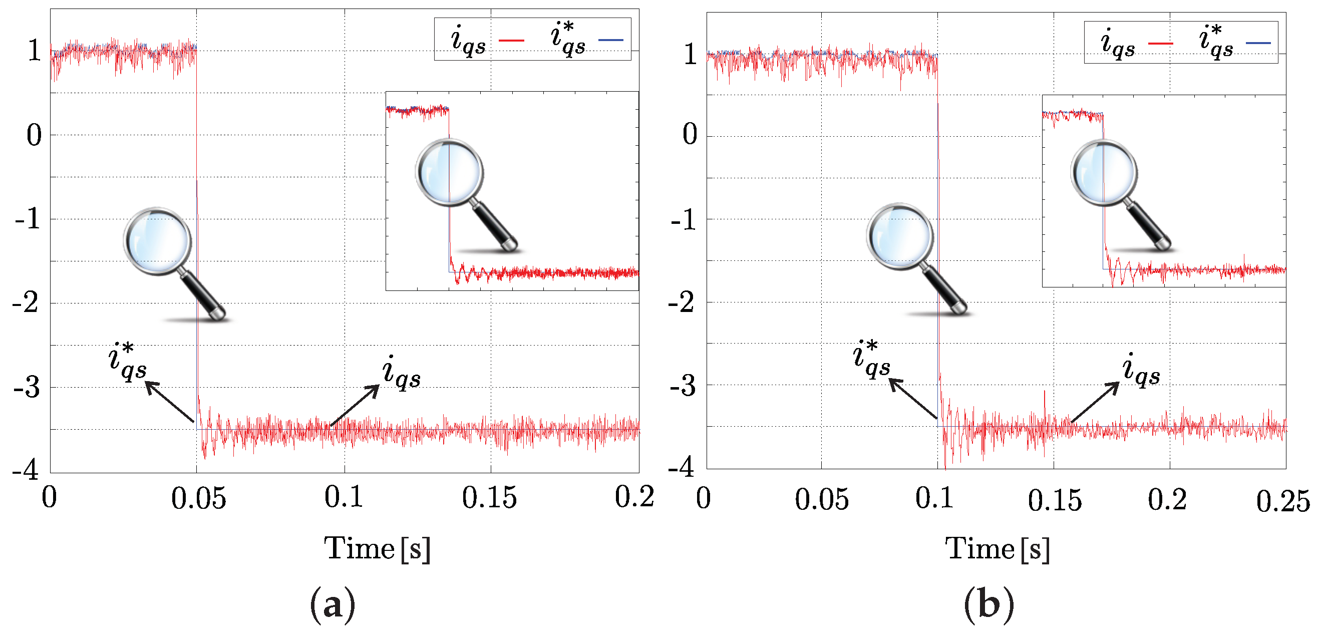
On the other hand, Figure 9 exposes the transient response of the proposed control for a step response in q axis. The transient response has been included through a reversal test from rotor mechanical speed (500 rpm to −500 rpm) at 8 kHz. Both cases report fast responses considering the overshoot and settling time, which were of 6.14% and 6 ms, respectively, for Figure 9a and 4.85% and 6.12 ms, respectively for Figure 9b. The criterion of the 5% has been selected. Finally, a experimental transient response from a step change of 1500 rpm to 200 rpm between classic MPC and PFSCCS has been depicted in Figure 10 in order to show the performance of the proposed strategy, which it has demonstrated that it can be used in industrial applications (e.g., regenerating braking).
5. Conclusions
In this paper, a predictive current control technique with a fixed switching frequency applied to a six-phase IM has been proposed. This technique has been developed to reduce the stator currents in the (x-y) frame using the largest vectors of the (-) frame with a stage of modulation based on a determined switching pattern in order to produce a fixed switching frequency. The simulation and experimental results have shown the performance of the proposed technique, where the system has been tested under different conditions (steady and transient conditions) including different rotor mechanical speeds, sampling frequency and tuning parameters for (x-y) stator currents, respectively. In terms of (-) currents tracking, the presented technique has a better behavior at lower speed and a remarkable reduction of (x-y) stator currents compared to classic MPC. The obtained results have also demonstrated a good transient current behavior in terms of overshoot and settling time. In summary, the proposed current control technique is a good alternative both in low and high speeds for industrial applications.
Author Contributions
Conceptualization, O.G., M.A. and J.R.; methodology, O.G., M.A.; software, M.A. and O.G.; validation, O.G., M.A. and J.D.-G.; formal analysis, O.G., M.A., J.D.-G., J.R., R.G. and M.R.; investigation, O.G. and M.A.; resources, J.D.-G.; data curation, J.D.-G., O.G. and M.A.; writing, original draft preparation, O.G., M.A. and J.R.; writing, review and editing, O.G., M.A., J.R., J.D.-G., R.G. and M.R.; visualization, J.D.-G., M.A., J.R., R.G. and M.R.; project administration, O.G., M.A., J.R., and J.D.-G.; funding acquisition, R.G. and J.R.
Funding
This research has been funded through the Consejo Nacional de Ciencia y Tecnología (CONACYT)-Paraguay, Grant Number POSG16-05 and FONDECYT Regular 1160690 Research Project.
Acknowledgments
The authors would like to thank members of the LSPyC, APET and LECPE for their significant comments on this work.
Conflicts of Interest
The authors declare no conflict of interest.
Abbreviations
The following abbreviations have been employed in this work:
| FOC | Field Oriented Control |
| IM | Induction Machine |
| MPC | Model Predictive Control |
| PFSCCS | Predictive-Fixed Switching Current Control Strategy |
| MSE | Mean Squared Error |
| PI | Proportional-Integral |
| PWM | Pulse-Width Modulation |
| SVM | Space Vector Modulation |
| THD | Total Harmonic Distortion |
| VSI | Voltage Source Inverter |
| VSD | Vector Space Decomposition |
References
- Duran, M.J.; Levi, E.; Barrero, F. Multiphase Electric Drives: Introduction. In Wiley Encyclopedia of Electrical and Electronics Engineering; Available online: https://onlinelibrary.wiley.com/doi/abs/10.1002/047134608X.W8364 (accessed on 26 April 2019).
- Precup, R.E.; Kamal, T.; Hassan, S.Z. Advanced Control and Optimization Paradigms for Wind Energy Systems; Springer: Berlin/Heidelberg, Germany, 2019. [Google Scholar]
- Subotic, I.; Bodo, N.; Levi, E. Integration of six-phase EV drivetrains into battery charging process with direct grid connection. IEEE Trans. Energy Conv. 2017, 32, 1012–1022. [Google Scholar] [CrossRef]
- Ayala, M.; Gonzalez, O.; Rodas, J.; Gregor, R.; Doval-Gandoy, J. A speed-sensorless predictive current control of multiphase induction machines using a Kalman filter for rotor current estimator. In Proceedings of the 2016 International Conference on Electrical Systems for Aircraft, Railway, Ship Propulsion and Road Vehicles & International Transportation Electrification Conference (ESARS-ITEC), Toulouse, France, 2–4 November 2016; pp. 1–6. [Google Scholar]
- Munim, W.N.W.A.; Duran, M.J.; Che, H.S.; Bermúdez, M.; González-Prieto, I.; Rahim, N.A. A unified analysis of the fault tolerance capability in six-phase induction motor drives. IEEE Trans. Power Electron. 2017, 32, 7824–7836. [Google Scholar] [CrossRef]
- Jones, M.; Vukosavic, S.N.; Dujic, D.; Levi, E. A synchronous current control scheme for multiphase induction motor drives. IEEE Trans. Energy Conv. 2009, 24, 860–868. [Google Scholar] [CrossRef]
- Kali, Y.; Ayala, M.; Rodas, J.; Saad, M.; Doval-Gandoy, J.; Gregor, R.; Benjelloun, K. Current Control of a Six-Phase Induction Machine Drive based on Discrete-Time Sliding Mode with Time Delay Estimation. Energies 2019, 12, 170. [Google Scholar] [CrossRef]
- Che, H.S.; Duran, M.J.; Levi, E.; Jones, M.; Hew, W.P.; Rahim, N.A. Postfault operation of an asymmetrical six-phase induction machine with single and two isolated neutral points. IEEE Trans. Power Electron. 2014, 29, 5406–5416. [Google Scholar] [CrossRef]
- Mirzaeva, G.; Goodwin, G.C.; McGrath, B.P.; Teixeira, C.; Rivera, M. A generalized MPC framework for the design and comparison of VSI current controllers. IEEE Trans. Ind. Electron. 2016, 63, 5816–5826. [Google Scholar] [CrossRef]
- Vazquez, S.; Rodriguez, J.; Rivera, M.; Franquelo, L.G.; Norambuena, M. Model Predictive Control for Power Converters and Drives: Advances and Trends. IEEE Trans. Ind. Electron. 2016, 64, 935–947. [Google Scholar] [CrossRef]
- Barrero, F.; Arahal, M.R.; Gregor, R.; Toral, S.; Durán, M.J. A proof of concept study of predictive current control for VSI-driven asymmetrical dual three-phase AC machines. IEEE Trans. Ind. Electron. 2009, 56, 1937–1954. [Google Scholar] [CrossRef]
- Barrero, F.; Prieto, J.; Levi, E.; Gregor, R.; Toral, S.; Durán, M.J.; Jones, M. An enhanced predictive current control method for asymmetrical six-phase motor drives. IEEE Trans. Ind. Electron. 2011, 58, 3242–3252. [Google Scholar] [CrossRef]
- Lim, C.S.; Levi, E.; Jones, M.; Rahim, N.A.; Hew, W.P. FCS-MPC-based current control of a five-phase induction motor and its comparison with PI-PWM control. IEEE Trans. Ind. Electron. 2013, 61, 149–163. [Google Scholar] [CrossRef]
- Vijayagopal, M.; Zanchetta, P.; Empringham, L.; De Lillo, L.; Tarisciotti, L.; Wheeler, P. Modulated model predictive current control for direct matrix converter with fixed switching frequency. In Proceedings of the 2015 17th European Conference on Power Electronics and Applications (EPE’15 ECCE-Europe), Geneva, Switzerland, 8–10 September 2015; pp. 1–10. [Google Scholar]
- Gregor, R.; Rodas, J.; Munoz, J.; Ayala, M.; Gonzalez, O.; Gregor, D. Predictive-Fixed Switching Frequency Technique for 5-Phase Induction Motor Drives. In Proceedings of the 2016 International Symposium on Power Electronics, Electrical Drives, Automation and Motion (SPEEDAM), Anacapri, Italy, 22–24 June 2016. [Google Scholar]
- Ayala, M.; Gonzalez, O.; Rodas, J.; Gregor, R.; Rivera, M. Predictive control at fixed switching frequency for a dual three-phase induction machine with Kalman filter-based rotor estimator. In Proceedings of the 2016 IEEE International Conference on Automatica (ICA-ACCA), Curico, Chile, 19–21 October 2016; pp. 1–6. [Google Scholar]
- Rivera, M.; Toledo, S.; Baier, C.; Tarisciotti, L.; Wheeler, P.; Verne, S. Indirect predictive control techniques for a matrix converter operating at fixed switching frequency. In Proceedings of the 2017 IEEE International Symposium on Predictive Control of Electrical Drives and Power Electronics (PRECEDE), Pucón, Chile, 18–20 October 2017; pp. 13–18. [Google Scholar]
- Comparatore, L.; Gregor, R.; Rodas, J.; Pacher, J.; Renault, A.; Rivera, M. Model based predictive current control for a three-phase cascade H-bridge multilevel STATCOM operating at fixed switching frequency. In Proceedings of the 2017 IEEE 8th International Symposium on Power Electronics for Distributed Generation Systems (PEDG), Florianopolis, Brazil, 17–20 April 2017; pp. 1–6. [Google Scholar]
- Harnefors, L.; Saarakkala, S.; Hinkkanen, M. Speed Control of Electrical Drives Using Classical Control Methods. IEEE Trans. Ind. Appl. 2013, 49, 889–898. [Google Scholar] [CrossRef]
- Zhao, Y.; Lipo, T. Space vector PWM control of dual three-phase induction machine using vector space decomposition. IEEE Trans. Ind. Electron. 1995, 31, 1100–1109. [Google Scholar]
- Ayala, M.; Rodas, J.; Gregor, R.; Doval-Gandoy, J.; Gonzalez, O.; Saad, M.; Rivera, M. Comparative Study of Predictive Control Strategies at Fixed Switching Frequency for an Asymmetrical Six-Phase Induction Motor Drive. In Proceedings of the 2017 IEEE International Electric Machines and Drives Conference (IEMDC), Miami, FL, USA, 21–24 May 2017; pp. 1–8. [Google Scholar]
- Rodas, J.; Barrero, F.; Arahal, M.R.; Martin, C.; Gregor, R. On-Line Estimation of Rotor Variables in Predictive Current Controllers: A Case Study Using Five-Phase Induction Machines. IEEE Trans. Ind. Electron. 2016, 63, 5348–5356. [Google Scholar] [CrossRef]
- Rodas, J.; Martin, C.; Arahal, M.R.; Barrero, F.; Gregor, R. Influence of Covariance-Based ALS Methods in the Performance of Predictive Controllers with Rotor Current Estimation. IEEE Trans. Ind. Electron. 2017, 64, 2602–2607. [Google Scholar] [CrossRef]
- Pandit, J.K.; Aware, M.V.; Nemade, R.V.; Levi, E. Direct torque control scheme for a six-phase induction motor with reduced torque ripple. IEEE Trans. Power Electron. 2017, 32, 7118–7129. [Google Scholar] [CrossRef]
- Gonzalez, O.; Ayala, M.; Rodas, J.; Gregor, R.; Rivas, G.; Doval-Gandoy, J. Variable-Speed Control of a Six-Phase Induction Machine using Predictive-Fixed Switching Frequency Current Control Techniques. In Proceedings of the 2018 9th IEEE International Symposium on Power Electronics for Distributed Generation Systems (PEDG), Charlotte, NC, USA, 25–28 June 2018; pp. 1–6. [Google Scholar]
- Yepes, A.G.; Riveros, J.A.; Doval-Gandoy, J.; Barrero, F.; López, O.; Bogado, B.; Jones, M.; Levi, E. Parameter identification of multiphase induction machines with distributed windings Part 1: Sinusoidal excitation methods. IEEE Trans. Energy Conv. 2012, 27, 1056–1066. [Google Scholar] [CrossRef]
- Riveros, J.A.; Yepes, A.G.; Barrero, F.; Doval-Gandoy, J.; Bogado, B.; Lopez, O.; Jones, M.; Levi, E. Parameter identification of multiphase induction machines with distributed windings Part 2: Time-domain techniques. IEEE Trans. Energy Conv. 2012, 27, 1067–1077. [Google Scholar] [CrossRef]
Figure 1.
Six-phase IM topology supplied trough a two-level six-phase VSI.

Figure 2.
Mapping of the space vectors in the (-)-(x-y) frame for a two-level six-phase VSI.

Figure 3.
Complete diagram of the PFSCCS applied to six-phase IM.

Figure 4.
Considered sectors for the six-phase VSI in the (-) frame: (a) Available vectors; (b) A selected specific sector shown as zoom.
Figure 4.
Considered sectors for the six-phase VSI in the (-) frame: (a) Available vectors; (b) A selected specific sector shown as zoom.

Figure 5.
Simulation performance in steady-state condition of stator currents in (-) and (x-y) sub-spaces for a sampling frequency of 8 kHz at different speeds (): (a) 500 rpm; (b) 1000 rpm; (c) 1500 rpm.
Figure 5.
Simulation performance in steady-state condition of stator currents in (-) and (x-y) sub-spaces for a sampling frequency of 8 kHz at different speeds (): (a) 500 rpm; (b) 1000 rpm; (c) 1500 rpm.

Figure 6.
Experimental test rig.

Figure 7.
Experimental results in the (-)-(x-y) frame for stator currents at 8 kHz of sampling frequency and 500 rpm rotor speed considering: (a) = 0.05; (b) = 0.1.
Figure 7.
Experimental results in the (-)-(x-y) frame for stator currents at 8 kHz of sampling frequency and 500 rpm rotor speed considering: (a) = 0.05; (b) = 0.1.

Figure 8.
Experimental performance for PFSCCS at 8 kHz of sampling frequency and 500 rpm: (a) Spectrum of the measured stator current; (b) Switching pattern in the VSI.
Figure 8.
Experimental performance for PFSCCS at 8 kHz of sampling frequency and 500 rpm: (a) Spectrum of the measured stator current; (b) Switching pattern in the VSI.

Figure 9.
Experimental transient test in q-axis of stator currents from a speed change of 500 rpm to rpm at 8 kHz of sampling frequency considering: (a) = 0.05; (b) = 0.1.
Figure 9.
Experimental transient test in q-axis of stator currents from a speed change of 500 rpm to rpm at 8 kHz of sampling frequency considering: (a) = 0.05; (b) = 0.1.

Figure 10.
Experimental transient test in q-axis of stator currents from a speed change of 1500 rpm to 200 rpm at 16 kHz and 8 kHz of sampling frequency, respectively: (a) Classic MPC; (b) PFSCCS.
Figure 10.
Experimental transient test in q-axis of stator currents from a speed change of 1500 rpm to 200 rpm at 16 kHz and 8 kHz of sampling frequency, respectively: (a) Classic MPC; (b) PFSCCS.


Table 1.
Characteristics of the six-phase IM.
| 6.9 | 654.4 mH | ||
| 12.8 mH | 626.8 mH | ||
| 5.3 mH | 2 kW | ||
| 6.7 | 0.07 kg.m | ||
| 614 mH | 0.0004 kg.m/s | ||
| P | 1 | 3000 rpm |
Table 2.
Simulation performance test of stator currents (-), (x-y), MSE (A), THD (%) at different rotor speeds (rpm).
Table 2.
Simulation performance test of stator currents (-), (x-y), MSE (A), THD (%) at different rotor speeds (rpm).
| = kHz | ||||||
|---|---|---|---|---|---|---|
| MSE | MSE | MSE | MSE | THD | THD | |
| 500 | 0.065 | 0.064 | 0.174 | 0.172 | 5.73 | 5.46 |
| 1000 | 0.076 | 0.075 | 0.211 | 0.203 | 5.43 | 5.34 |
| 1500 | 0.110 | 0.110 | 0.219 | 0.216 | 6.46 | 6.38 |
Table 3.
Experimental performance test of stator currents (-), (x-y), MSE (A), THD (%) between classic MPC and the PFSCCS at different rotor speeds (rpm).
Table 3.
Experimental performance test of stator currents (-), (x-y), MSE (A), THD (%) between classic MPC and the PFSCCS at different rotor speeds (rpm).
| = 8 kHz for Classic MPC | ||||||
| MSE | MSE | MSE | MSE | THD | THD | |
| 500 | 0.140 | 0.130 | 0.821 | 0.822 | 8.30 | 8.40 |
| 1000 | 0.147 | 0.138 | 0.953 | 0.934 | 7.40 | 7.30 |
| = 16 kHz for Classic MPC | ||||||
| MSE | MSE | MSE | MSE | THD | THD | |
| 500 | 0.073 | 0.072 | 0.491 | 0.483 | 8.40 | 8.30 |
| 1000 | 0.084 | 0.082 | 0.538 | 0.534 | 7.50 | 7.40 |
| = 8 kHz for PFSCCS | ||||||
| MSE | MSE | MSE | MSE | THD | THD | |
| 500 | 0.042 | 0.045 | 0.135 | 0.130 | 4.89 | 5.08 |
| 1000 | 0.069 | 0.068 | 0.197 | 0.204 | 4.69 | 4.78 |
© 2019 by the authors. Licensee MDPI, Basel, Switzerland. This article is an open access article distributed under the terms and conditions of the Creative Commons Attribution (CC BY) license (http://creativecommons.org/licenses/by/4.0/).
Share and Cite
MDPI and ACS Style
Gonzalez, O.; Ayala, M.; Doval-Gandoy, J.; Rodas, J.; Gregor, R.; Rivera, M. Predictive-Fixed Switching Current Control Strategy Applied to Six-Phase Induction Machine. Energies 2019, 12, 2294. https://doi.org/10.3390/en12122294
AMA Style
Gonzalez O, Ayala M, Doval-Gandoy J, Rodas J, Gregor R, Rivera M. Predictive-Fixed Switching Current Control Strategy Applied to Six-Phase Induction Machine. Energies. 2019; 12(12):2294. https://doi.org/10.3390/en12122294
Chicago/Turabian StyleGonzalez, Osvaldo, Magno Ayala, Jesus Doval-Gandoy, Jorge Rodas, Raul Gregor, and Marco Rivera. 2019. "Predictive-Fixed Switching Current Control Strategy Applied to Six-Phase Induction Machine" Energies 12, no. 12: 2294. https://doi.org/10.3390/en12122294
Note that from the first issue of 2016, this journal uses article numbers instead of page numbers. See further details here.