Article

Suggestion of a New Protection Scheme for a Transmission System Equipped with a Thyristor-Controlled Series Capacitor

1
Department of Electrical Engineering, Changwon National University, Changwon 51140, Korea
2
Korea Electric Power Research Institute, Seoul 34056, Korea
*
Author to whom correspondence should be addressed.
Energies 2019, 12(12), 2250; https://doi.org/10.3390/en12122250
Submission received: 3 May 2019 / Revised: 1 June 2019 / Accepted: 10 June 2019 / Published: 12 June 2019
(This article belongs to the Special Issue Electric Power Systems Research 2019)

Abstract

:
A thyristor-controlled series capacitor (TCSC) is employed to a transmission line in order to enhance the usable capacity of the present as well as upgraded lines, improve system stability, reduce losses, and improve power flow control capability. However, in an abnormal situation, the TCSC may transit from the existing operation mode to the other mode according to its control system and protection strategy. There is much difference in the impedance of the TCSC between each mode. This threatens the reliability of the conventional protection system, especially the distance relay, that works based on the measurement of line impedance. In this paper, we suggest a new protection scheme for a distance relay of a transmission line equipped with a TCSC. In the suggested method, in order to mitigate the effect of the TCSC in the fault loop, the TCSC injected voltage is subtracted from the measured phase voltage before supplying the voltage signal to the distance relay. The suggested scheme was verified by a real time digital simulator (RTDS)-based closed-loop test bed of a protective relay. The effect of the TCSC in the fault loop was completely mitigated. The distance relay works properly with the suggested scheme.

1. Introduction

In recent years, the increase in power demands requires the expansion of power generation and transmission. However, the expansion meets the limit due to environment and resource restriction. To overcome this problem, flexible alternating current transmission system (FACTS) technology, such as thyristor-controlled series capacitors (TCSC) and high voltage alternating current (HVDC), is one of the possible solutions because it enhances the usable capacity of the transmission facilities and system reliability. TCSC is one of the most critical devices in the FACTS family. By compensating the transmission line impedance, the TCSC enhances the power transfer capability and opens up the power control capability for the present and upgraded lines [1,2,3].
A TCSC consists of a capacitor (C) connected in parallel with a thyristor-controlled reactor (TCR). The TCSC module also has different protective elements, such as a metal oxide varistor (MOV) or a bypass circuit breaker (CB), connected in parallel with its main circuit. The TCSC has four operation modes: bypassed-thyristor mode, blocked-thyristor mode, capacitive vernier mode, and inductive vernier mode. In normal operation, the TCSC is operated at the capacitive vernier mode to compensate the transmission line impedance [4]. In order to protect the TCSC capacitor from over-voltage, the MOV connected in parallel with the TCSC capacitor will operate. Besides this, in some severe situation like faults or equipment malfunctions, if the MOV cannot handle the TCSC capacitor over-voltage completely, the bypass CB will close to bypass the high current. The bypass CB is also activated when the energy of the MOV exceeds its certain threshold level.
During a fault, different operation modes could incorporate with the TCSC protection equipment. Therefore, the operation modes are as follows: blocked mode with/without MOV, capacitive mode with/without MOV, TCSC bypass, CB bypass.
Depending on the pre-fault and fault conditions, the TCSC may switch from the existing mode to the other mode according to its control and protection strategy. There is much difference in the impedance of the TCSC between each mode, so the transition from one mode to another may cause malfunctions of the conventional distance relay, such as forward over-reach, reverse over-reach, and direction malfunction [5].
Many research papers have indicated that the TCSC affects the protection of its line as well as the protection of adjacent lines. The problems are over-reach, miscoordination in primary and backup protections, and directional malfunction [6,7,8]. Some approaches have been introduced to overcome the problems. In Ref. [7], the authors introduced a new setting for a distance relay, in which the new setting impedance was set to the conventional setting impedance minus the biggest compensated reactance of the TCSC. This method can reduce the misoperation of the distance relay in the external fault and reverse direction fault, however, the protection range is reduced. In Ref. [9], the authors introduced the distance protection setting method based on the modified particle swarm optimization (MPSO) techniques. The MPSO was used to calculate the distance relay setting for the inductive and capacitive modes of the TCSC. However, how the distance relay works with two different settings, and the adjustment of the relay setting when the TCSC changes from the boost modes (inductive and capacitive) to the bypass mode, or when the operation modes are incorporated with the protection equipment was not discussed. Reference [10] described a new high-speed MHO distance protection scheme for single-line-to-ground faults in the TCSC line. In this scheme, the TCSC reactance is subtracted from the total fault impedance to mitigate the effect of the TCSC in the fault loop. However, the TCSC reactance was defined based on the firing angle from the TCSC, so the TCSC impedance will not be estimated correctly when the protection equipment, like the MOV or bypass CB, operates. In Ref. [11], modified communication-aided distance protection schemes were introduced. However, the protection zone of those methods is just the main protected line; they cannot be used as back-up protection for the adjacent lines. In Ref. [12], the average voltage and current-based fast protection scheme for detecting the fault direction was introduced. [13] presented an impedance measurement at multiple frequencies for detecting whether or not the series capacitor is in the fault loop. The detection of a TCSC in the fault loop was not discussed in detail. In Ref. [14], in order to eliminate the effect of the TCSC, a fault current limiter (FCL) was supposed to be installed in series with the TCSC. With this method, an additional device is needed. In conclusion, the impedance measurements-based protection schemes still have some problems. They are not able to overcome the mal-operation of the distance relay in all possible operation modes of the TCSC. The protection range is reduced or the back-up protection function for the adjacent lines is lost. After all, the installation of TCSC in a transmission system will threaten the reliability and security of the power system if the existing protection system of the transmission line is not adjusted or replaced.
So, in this paper, we suggest a new protection scheme named as the voltage compensator scheme for a transmission line equipped with a TCSC. This method can eliminate the effect of the TCSC in the fault loop and secure the proper operation of the distance relay in all possible operation modes of the TCSC without modifying the relay setting. In the suggested method, the TCSC injected voltage is subtracted from the measured phase voltage to eliminate the effect of the TCSC in the fault loop. We also implemented a real time digital simulator (RTDS)-based closed-loop test of a protective relay that incorporates a commercial protective relay device with the simulated utility grid system to verify the suggested method.
The simulation demonstrated that the effect of TCSC in the fault loop was completely mitigated and the distance relay works properly with the suggested scheme.

2. The Operating Principle and Parameters of TCSC

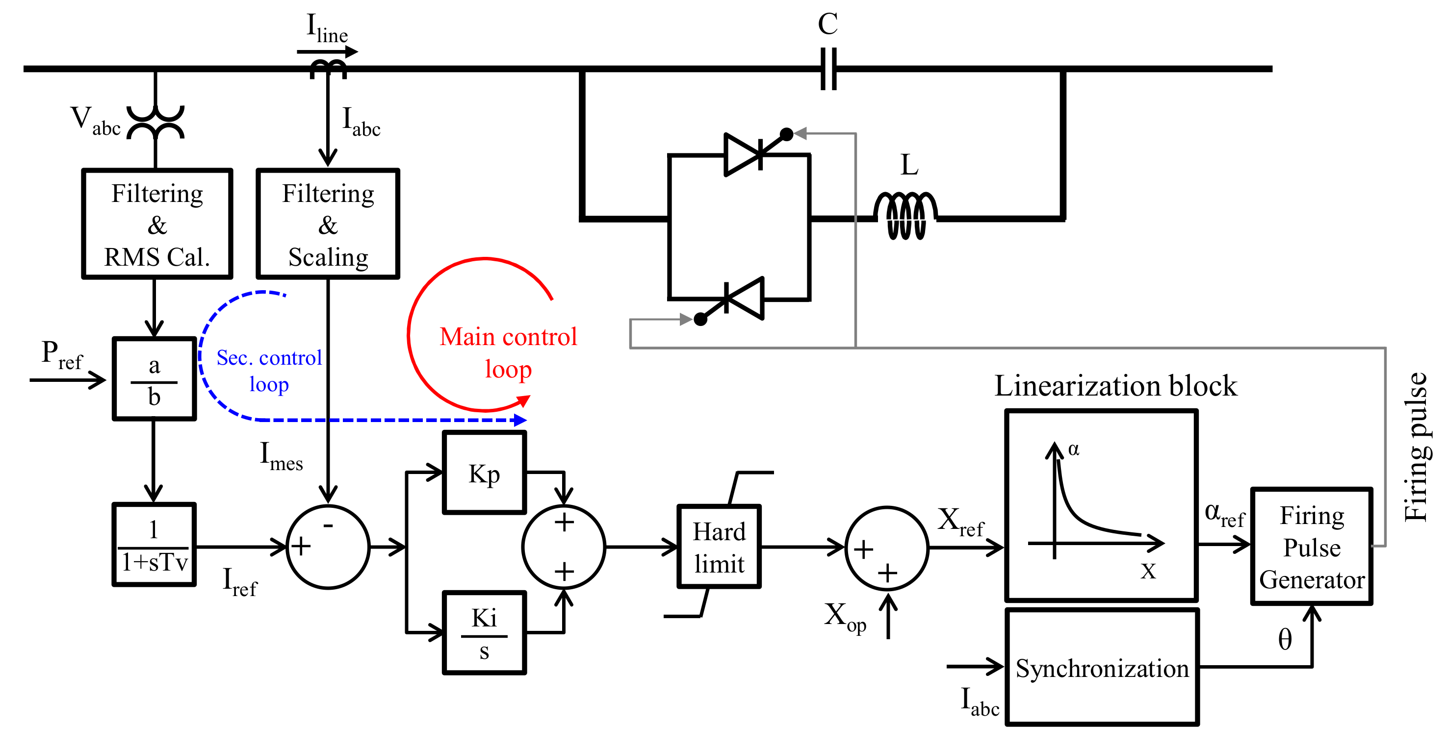
2.1. The Operating Principle of TCSC

There are four operation modes of a TCSC: bypassed-thyristor mode, blocked-thyristor mode, capacitive vernier mode, and inductive vernier mode. In the bypassed mode, the thyristors conduct entirely with a conduction angle of 180°. The TCSC module behaves like a parallel capacitor–inductor combination. In the blocked-thyristor mode, the TCSC controller blocks the firing pulses to the thyristor valves. The thyristor current is zero. It is also known as the waiting mode. The capacitive vernier mode allows the TCSC to behave as a continuously controllable capacitive reactance. In this mode, the TCSC controller will adjust the thyristor firing angle in a proper range. In the inductive vernier mode, the TCSC behaves as a continuously controllable inductive reactance. In general, the inductive vernier mode is not used.
In order to protect the TCSC capacitor from over-voltage, the MOV that is connected in parallel with the TCSC capacitor will operate. Also, in some severe situations, like faults or equipment malfunctions, if the MOV cannot handle the TCSC capacitor over-voltage completely, the bypass CB installed across the TCSC module will close to bypass the high current. This mode is also activated when the energy of the MOV exceeds its certain threshold level.
Figure 1 shows the configuration of a 345 kV transmission system, including a series compensation device. The series compensation device is composed of an FSC and a TCSC. The FSC and TCSC have their MOVs. The bypass CB is across both the FSC and TCSC to protect them from over-voltage. Figure 2 shows the mode sequence of the FSC and TCSC during a fault. If the fault current is more significant than 1.5 times the rated current, the TCSC will change to the bypassed-TCSC mode. If the fault current is more significant than 2.2 times the rated current or the energy of the FSC MOV or TCSC MOV exceeds the threshold value, the TCSC will switch to the bypassed-CB mode. During a fault, different modes of operation could incorporate with the TCSC protection equipment. The possible operation modes and the TCSC impedance characteristics are summarized in Table 1.

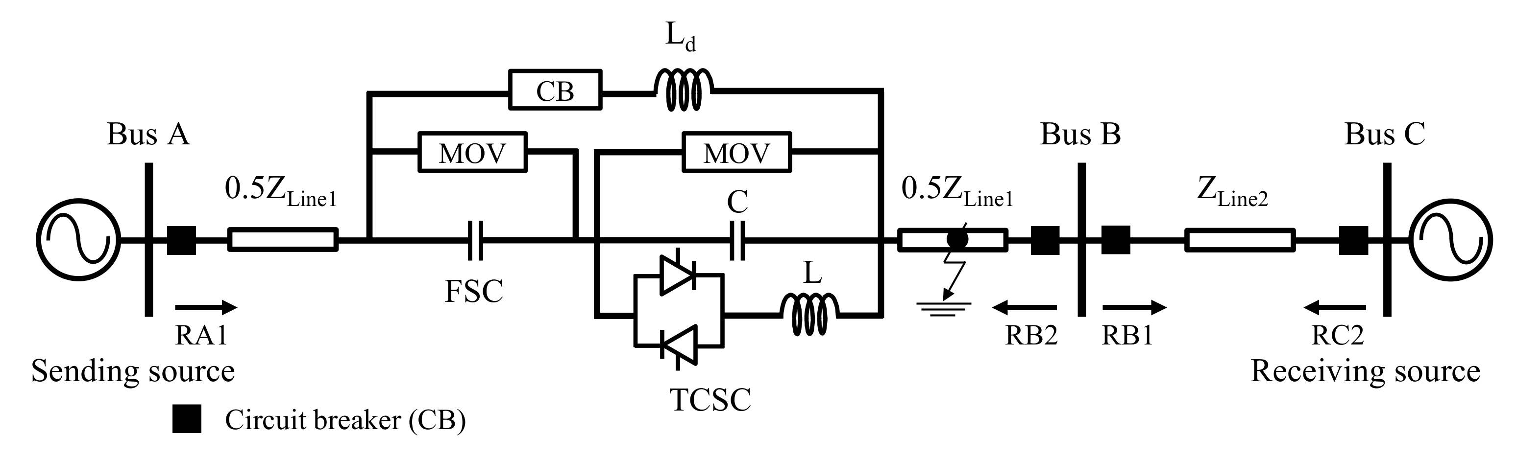
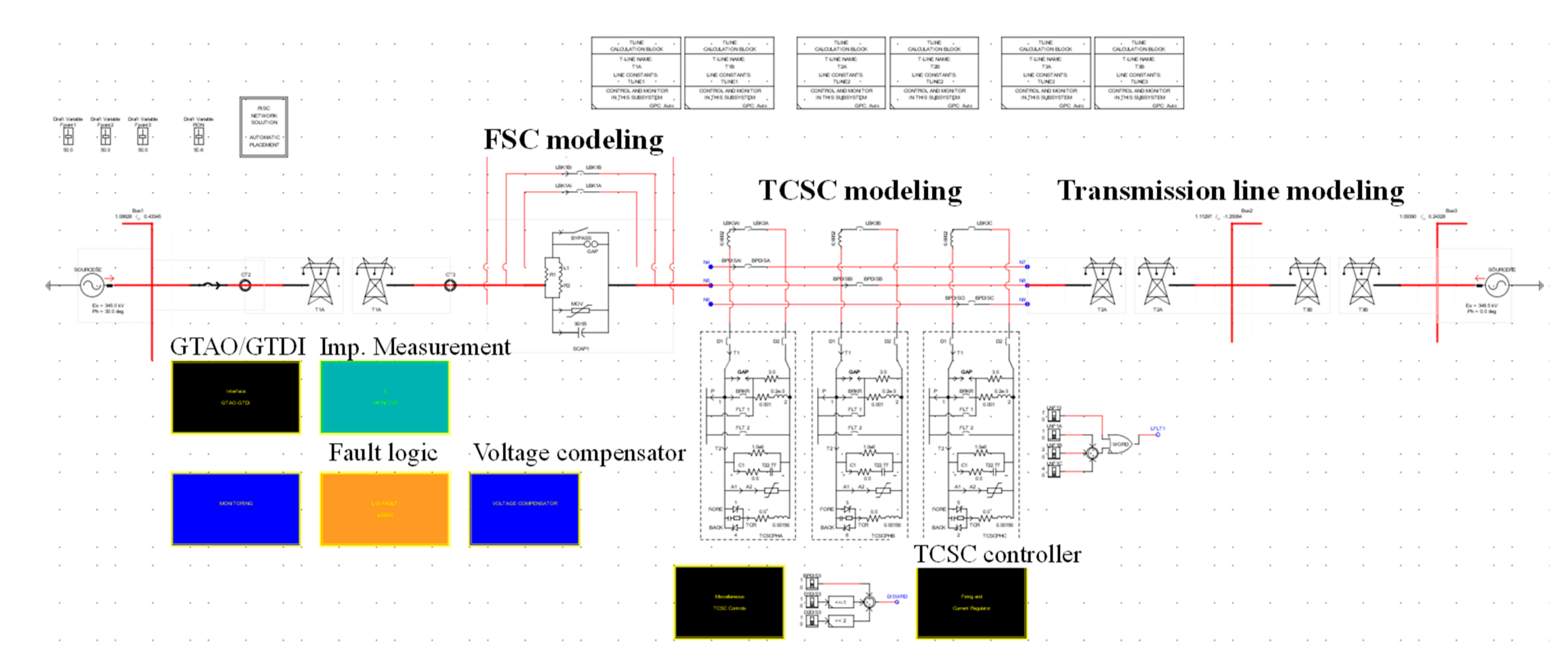
2.2. Configuration of the 345 kV Transmission System equipped with the TCSC

The 345 kV test power system equipped with a 345 kV TCSC is depicted in Figure 1. The system includes two transmission lines and three buses. Bus A is connected to a sending source, and bus C is connected to a receiving source. The phase angle difference between the sending and receiving sources causes the power flow in the system. The lengths of line 1 and line 2 are 200 km and 100 km, respectively. Moreover, their distributed parameters are summarized in Table 2. Series compensation devices include the FSC and TCSC. The capacitance of the FSC capacitor is 90.35 μF, corresponding to 40% compensation degree. The compensation devices are located in the middle of line 1.
As shown in Figure 1, the typical configuration of a TCSC includes two critical parts. One is the controllable-segment, which is composed of a fixed capacitor (FC) and a TCR. The other is protection devices, including the metal oxide varistor (MOV) and bypass CB branch. Table 3 shows the parameters of the 345 kV TCSC, and Table 4 shows its operating characteristics [15].
The FSC and TCSC are equipped with two MOVs and a bypass CB as protective devices. MOV is a voltage-dependent, nonlinear resistor that can provide a new path for bypassing the fault current when the TCSC or FSC capacitor over-voltage occurs. The following exponential equation represents the MOV voltage (v)-current (i) characteristic [8,16]:
i M O V = I r e f ( v M O V V r e f ) n ,
where iMOV and vMOV are the MOV current and voltage, respectively, Iref and Vref are the reference quantities, n is the exponent of the characteristics.
A circuit breaker (CB) is installed across both the FSC and the TCSC to bypass it if a very high fault current or malfunction occurs. Moreover, a current limiting inductor, Ld, is installed in series with the bypass CB to limit the fault current. Table 5 represents the parameters of MOVs and bypass CB branch.
Figure 3 shows the block diagram of a typical TCSC controller. The TCSC controller is based on a proportional-integral (PI) regulator. It can be operated in the constant-impedance control, constant-current control, or power control [17].

3. Design of New Protection Scheme for the Transmission System Equipped with the TCSC

3.1. The Influence of TCSC on Distance Protection of the Transmission Line

As shown in Figure 1, the TCSC is in the middle of the transmission line 1. The impedance beyond the TCSC is measured by the relay RA1 at the bus A of line 1, as [5]:
Z m = d Z 1 L 1 + Z T C S C ,
where Zm is the impedance measured by the relay (Ω), d is the fault location (pu), ZTCSC is the TCSC impedance (Ω), and Z1L1 is the positive-sequence impedance of line 1 (Ω).
Dividing both sides of (2) by Z’m = dZ1L1, we obtain:
Z m Z m = 1 + k d ,
where k = ZTCSC/Z1L1. k represents the compensation degree when the TCSC is operated in the capacitive mode.
Figure 4 shows Zm/Z’m versus k for different values of fault location d. The figure indicates that the influence of a TCSC is critical to both reach and directionality of relay. For example, in the case of 50% compensation factor, when the fault occurs at the remote end of the line, i.e., d = 1.0, the relay over-reaches and Zm = 0.5Z1L1 instead of Z1L1. As seen in Figure 4, for 0.5 < d < 0.55, the relay would not see the fault in a forward direction, even for a normal operating point, before the TCSC mode changes. In the bypass mode, ZTCSC is positive, and the relay under-reaches slightly. Table 6 indicates the operation of distance relay under the different operation modes of the TCSC.

3.2. TCSC Voltage Compensator Scheme for Distance Relays in the presence of the TCSC

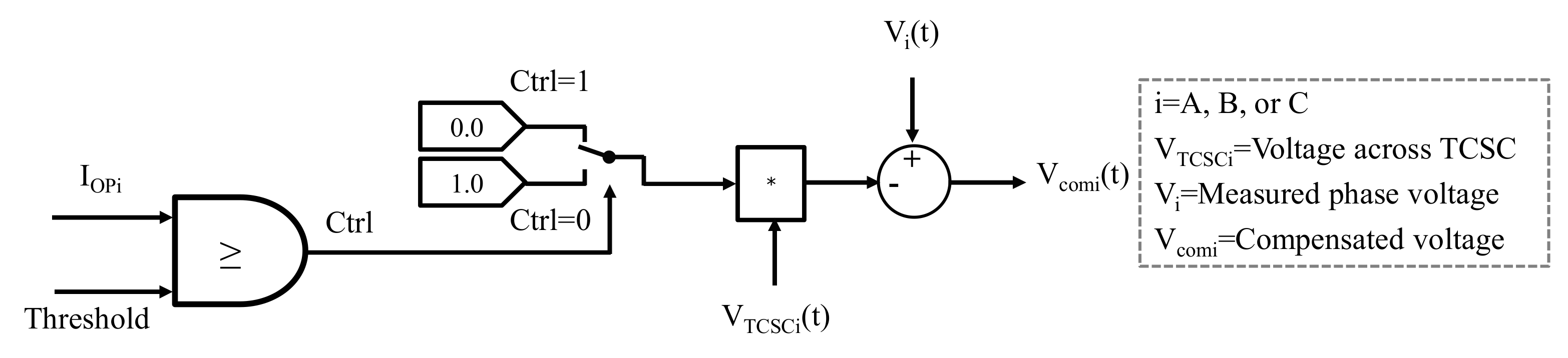
3.2.1. Voltage Compensator

The impact of the TCSC on the fault loop can be mitigated if the TCSC voltage (vTCSC(t)) is subtracted from the measured phase voltage v(t):
v c o m ( t ) = v ( t ) v T C S C ( t ) .
Then, the impedance measured by the relay is re-calculated. Figure 5a presents the sequence network interconnections of a phase-to-phase fault. For a phase-to-phase fault between phase B and phase C beyond the TCSC, phase B and C fault current are calculated as:
I B = a 2 I 1 + a I 2 = a 2 a I 1 I C = a I 1 + a 2 I 2 = a a 2 I 1 ,
where operator a = ej120°, I1, and I2 are positive- and negative-sequence components of the line current, respectively.
The sequence components of the voltage measured by the relay are:
V 1 = I 1 d × Z 1 L 1 + Z 1 T C S C   V 2 = I 2 d × Z 2 L 1 + Z 2 T C S C   ,
where Z1L1 and Z2L1 are the positive- and negative-sequence components of line 1 impedance, respectively, and Z1TCSC and Z2TCSC are the positive- and negative-sequence components of the TCSC impedance, respectively.
Thus, we have:
V 1 c o m p = V 1 V 1 T C S C = I 1 × dZ 1 L 1 V 2 c o m p = V 2 V 2 T C S C = I 2 × dZ 2 L 1 .
Phase B and phase C voltage are calculated as:
V B = a 2 V 1 c o m p + a V 2 c o m p = a 2 a I 1 d Z 1 L 1 V C = a V 1 c o m p + a 2 V 2 c o m p = a a 2 I 1 d Z 1 L 1 .
When the voltage across the TCSC is subtracted from the measured phase voltage, the impedance measured by the relay is:
Z B C = V B V C I B I C = a 2 a a a 2 I 1 d Z 1 L 1 a 2 a a a 2 I 1 = d Z 1 L 1 .
Figure 5b presents the sequence network interconnections of a single-line-to-ground fault. The sequence components of the voltage measured by the relay are:
V 1 = I 1 d × Z 1 L 1 + Z 1 T C S C   = I 1 × d Z 1 L 1 + V 1 T C S C V 2 = I 2 d × Z 2 L 1 + Z 2 T C S C   = I 2 × d Z 2 L 1 + V 2 T C S C V 0 = I 0 d × Z 0 L 1 + Z 0 T C S C = I 0 × d Z 0 L 1 + V 0 T C S C ,
where Z0L1 and Z0TCSC are the zero-sequence component of the line impedance and TCSC impedance, respectively. V1TCSC, V2TCSC, and V0TCSC are the sequence components (positive, negative, and zero) of the TCSC voltage.
In the case of the single-line-to-ground fault, the zero-sequence current (I0), the positive- sequence current (I1), and the negative-sequence current (I2) are equal, and Z1L1 is supposed to equal Z2L1, so that we can have:
V A = V 1 + V 2 + V 3 = I 1 2 d Z 1 L 1 + Z 0 L 1 + V T C S C A ;
I A = I 1 + I 2 + I 3 = 3 I 1 .
The zero-sequence compensation (ZSC) factor is defined as:
K 0 = Z 0 L 1 Z 1 L 1 3 Z 1 L 1 .
Finally, we have:
Z A N = V A V T C S C A 1 + K 0 I A = d Z 1 L 1 .
For the three-phase fault and the double phase-to-ground fault, the obtained result is the same as equation (9). Equations (9) and (14) demonstrate that the impedance measured by the relay is proportional to the distance from the fault point to the relay location only if the TCSC voltage is subtracted from the measured phase voltage. So, with the voltage compensator scheme, the setting for a distance relay of a transmission line equipped with a TCSC is designed based on the same manner that we use for the distance relay of the transmission line without the TCSC.

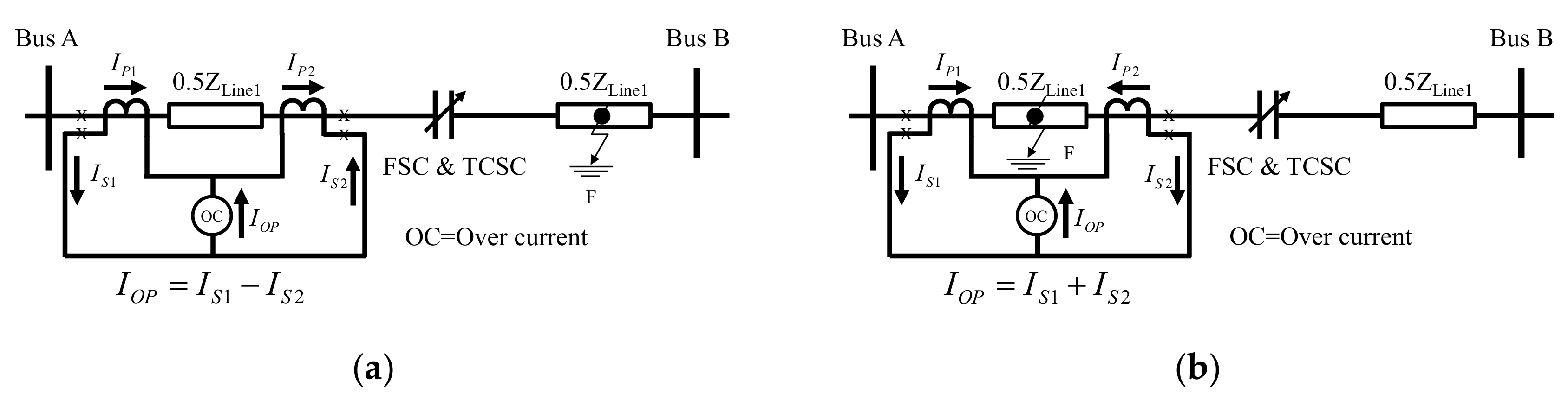
3.2.2. Detection of the TCSC in the Fault Loop

We consider the relay RA1 of line 1, as shown in Figure 1. When a fault occurs between the relay and the TCSC, the TCSC will not affect the impedance measurement of the relay RA1. However, if a fault occurs beyond the TCSC, the corresponding voltage across the TCSC (vTCSC(t)) should be subtracted from the measured phase voltage v(t) in order to mitigate the effect of TCSC, as described in Section 3.2.1. Thus, it is necessary to develop an algorithm that can detect whether the TCSC is inside or outside of the fault loop in order to decide when the voltage across TCSC should be compensated.
Two current transformers (CT) with the same type and ratio are installed at the bus A and the middle of line 1, as shown in Figure 6. When the fault occurs beyond the TCSC or the TCSC is in the fault loop, the operating current (IOP) flowing through the over-current relay (OC) is very small but not zero, due to the non-homogeneous characteristics of the CTs, as described in Figure 6a. When a fault occurs between the bus A and the series compensation devices, the operating current (IOP) is the sum of the input current feeding the fault, and it is quite significant. In this case, the TCSC is out of the fault loop, as depicted in Figure 6b. Based on this, we proposed the control logic in Figure 7. When IOP is higher or equal the threshold value, the output signal of the comparator (Ctrl) is 1—this means that the TCSC is out of the control loop. Thus, compensated voltage (vcom(t)) equals the phase voltage (v(t)). In contrast, when the TCSC is in the fault loop, “Ctrl” is 0 and the compensated voltage (vcom(t)) equals phase voltage (v(t)) minus the TCSC voltage (vTCSC(t)).

3.3. Distance Relay Setting

For the test system in Figure 1, the main setting design of the distance relay RA1 is presented in Table 7.
Z1L1 and Z0L1 denote the positive- and zero-sequence impedances of the transmission line 1, respectively. Z1L2 is the positive-sequence impedance of the transmission line 2 in Figure 1.

4. RTDS-Based Closed-Loop Test Bed of a Distance Relay

In order to confirm the suggested protection scheme, we performed the RTDS-based hardware in the loop simulation of a protective relay. As shown in Figure 8, the RTDS-based closed-loop test of a protective relay includes the test power system modeling using RTDS, fault detection, and feedback of the operation signals of the circuit breakers in the RTDS [18].
(1) The test power system modeling using RTDS
The test power system, including transmission lines, voltage sources, and circuit breaker (CB), is modeled using the RTDS library standard components. The models of the 345 kV FSC and TCSC were also developed and modeled in the RTDS.
(2) Fault detection
The current and voltage signals generated from RTDS are sent to the processing module of the relay via the gigabit transceiver analog output (GTAO) card of the RTDS and low-level test interface of an SEL-411L. Based on these signals, the practical relay SEL-411L will detect whether a fault occurs in the system. The TCSC voltage compensator scheme was developed and implemented in a real-time simulation environment (RTDS). Only the compensated voltages are sent to the relay SEL-411L.
(3) Feedback of the operation signals of the circuit breakers in the RTDS
The “OPEN” and “CLOSE” signals are sent from the relay to the RTDS via the gigabit transceiver digital input (GTDI) card. In this study, the relay model SEL-411L of Schweitzer Engineering Laboratories was incorporated with the test system model in the RTDS via the interface cards.
Figure 9 depicts the RTDS modeling of the 345 kV test power system with the FSC and the TCSC.

5. Results and Discussion

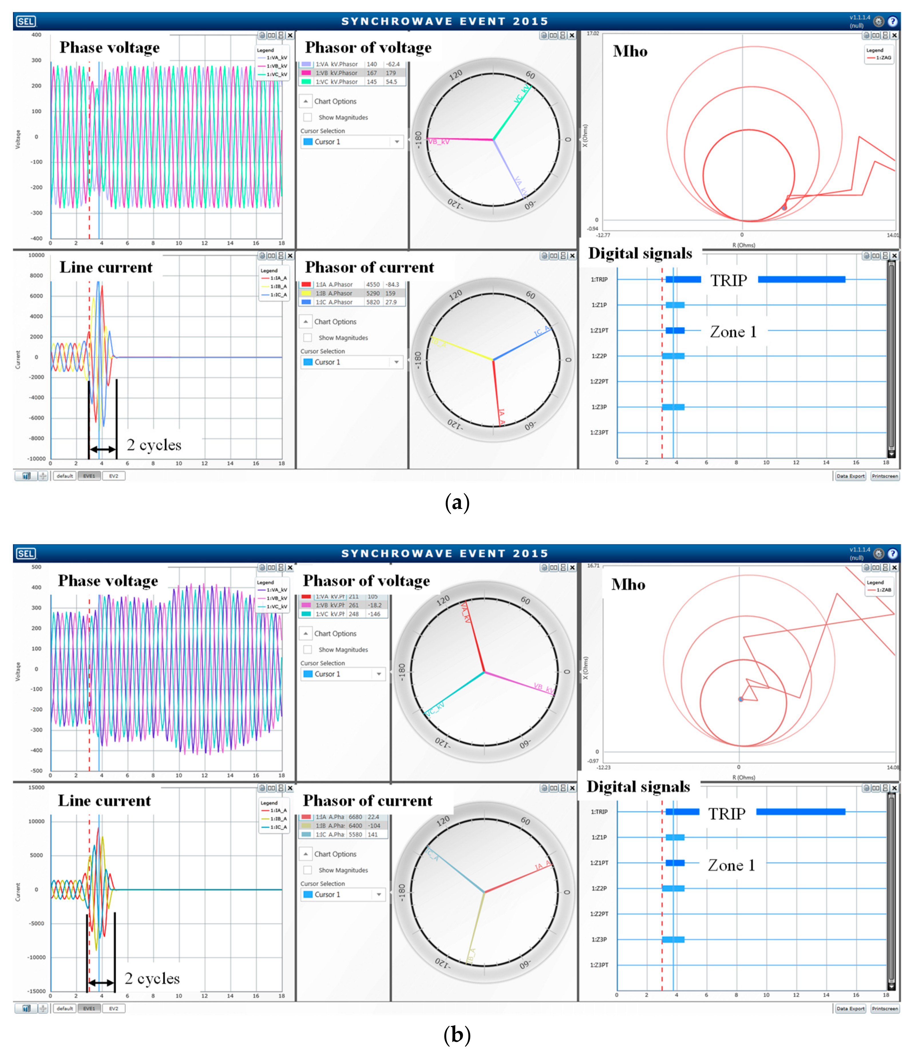
5.1. The Test Results

In order to demonstrate the effectiveness of the proposed scheme, the operating characteristics of the protection relay RA1 with both the conventional and proposed schemes were analyzed with different fault types and fault location along line AB and line BC. Within this study, the fault resistance was assumed to be a constant of 0.001 ohms. Before the fault, the TCSC was being operated under the capacitive mode, and its percentage compensation (kTCSC) was 10%. The percentage compensation of the FSC (kFSC) was a constant of 40%—the total compensation was 50%.
Figure 10 represents the analysis of operating characteristics of the protection relay RA1 for the three-phase fault in the middle of line 1 beyond the TCSC. Although the protection relay RA1 trips at zone 1 for both the conventional and proposed schemes, the measured impedances by the relay for both cases were different due to the injection of TCSC impedance.
Figure 11 indicates the analysis of the operating characteristics of the protection relay RA1 in the cases without and with the voltage compensator scheme during the fault at the remote end of line 1. In the case without the voltage compensator scheme, although the fault occured at the remote end of line 1, measured impedance was about 50% of the total line 1 impedance. Thus, relay over-reaches, and it trips at zone 1 simultaneously, as shown in Figure 11a. However, as presented in Figure 11b, the measured impedance equals the total line 1 impedance. The relay trips at zone 2 with 21 cycles time delay. These results prove the correctness of the proposed voltage compensator scheme.
Table 8 represents the results obtained for different fault types, fault location, and power system configurations of Figure 1. The results were obtained by using the RTDS-based closed-loop test of the commercial protective relay SEL-411L. For each fault point, four different fault types (three-phase, phase-to-phase, two-phase-to-ground, and single phase-to-ground) were checked. It was assumed that load always flows from left to right.
The impact of TCSC in the protection relay is summarized in Table 8, column “original protection scheme”. The commercial relay RA1 recorded the fault as three-phase instantaneous Zone 1 with the fault location up to +90% of line 2. This means that relay RA1 has significant over-reach for the forward faults. The same results were obtained for the other fault types (phase-to-phase, two-phase-to-ground). Zone 1 of RA1 has been extended beyond its setting at 85% of line 1. The overshoot of the control system after the fault could increase the degree of compensation and could make the over-reach of the distance relay more serious. Zone extensions of the phase-to-ground fault are only up to 50% of line 2.
However, as represented in Table 8, column “voltage compensator scheme”, when the voltage compensator scheme is applied, the impact of TCSC on distance protection is eliminated. Also, the RA1 operates properly, as designed. RA1 trips simultaneously at Zone 1 for all fault types up to 85% of line 1. It trips at Zone 2 for faults occurring at 85% of line 2 to 50% of line 3. If the fault point is beyond 50% of line 2, the RA1 trips in Zone 3. In Table 8, “Inst.” stands for “instantaneous”. It means that the relay operates instantaneously. And “time” means that the relay operates with time delay. “ABC”, “AB”, and “ABG” denote three-phase fault, phase-to-phase fault and two-phase-to-ground fault, respectively. “AG” means single-line-to-ground fault.

5.2. Discussion

In this paper, the authors proposed the voltage compensator scheme to overcome the problems of the distance protection for a transmission line equipped with a TCSC. The suggested method includes the following contents.
1. In order to mitigate the impact of the TCSC in the fault loop, the TCSC injected voltage was subtracted from the measured phase voltage to obtain the compensated phase voltage. Then, the compensated phase voltage was inputted to the relay instead of the measured phase voltage.
Thus, the voltage across the TCSC should be measured and sent to the relay via a communication channel. However, the voltage across the series FACT devices, like TCSC, can be estimated based on the locally available line current using the artificial neural network (ANN), as presented in [19]. With the second approach, the communication channel can be ignored.
2. Moreover, the TCSC injected voltage was subtracted from the measured phase voltage only when the TCSC belonged to the fault loop. Thus, we needed an algorithm that could detect whether or not the TCSC is in the fault loop. Inspired by the differential protection scheme, we suggested the detection of the TCSC in the fault loop algorithm and control logic in Section 3.2.2. However, another method can be used, as presented in [13]. A method of line impedance measurement at multiple frequencies revealed that it is possible to figure out whether or not the series compensated device is in the fault loop.
3. In this paper, the compensated phase voltage was implemented in the RTDS and inputted directly to the processing module of the relay SEL-411L. The conventional distance relay needs to be upgraded to handle the subtraction v(t) − vTCSC(t) and addition control logic presented in Section 3.2.2.
The proposed method can mitigate the effect of the TCSC in the fault loop and secure the proper operation of distance relay in all possible operation modes of the TCSC without modifying the relay setting. However, the drawback of the proposed method is that a communication channel and additional protection devices are needed. We think that the proposed method is very close to practical.
In order to verify the proposed scheme, we only used the MHO distance relay for testing the relay RA1. In the future, quadrilateral and polygonal characteristics of distance relay are expected to be implemented to verify the proposed scheme. The reverse protection function of distance relay or the effect of the fault resistance will be considered in future work.

6. Conclusions

In this paper, the authors analyzed the impact of a TCSC on the protection of transmission systems during a fault. The analysis was done by the detailed modeling of the power system and the FSC and TCSC using RTDS and the RTDS-based closed-loop test bed of a commercial protective relay. The operation characteristics of the affected distance relay were analyzed in both cases: the conventional protection scheme and the suggested voltage compensator scheme. The results indicate that the TCSC had a significant impact on the distance protection, like over-reach. However, the suggested voltage compensator scheme that subtracts the voltage across the TCSC from the measured phase voltage can overcome these problems well. It was confirmed successfully using the RTDS-based closed-loop test of the SEL-411L. The distance relay employed the suggested voltage compensator scheme operated adequately in all cases.

Author Contributions

Conceptualization, methodology, validation, writing—original draft preparation, writing—review and editing, M.-C.D.; software, M.-Q.T. and J.-I.L.; investigation, S.-J.L.; project administration, C.H.L. and J.Y.; supervision, M.P.

Funding

This work was funded by Korea Electric Power Corporation.

Conflicts of Interest

The authors declare no conflict of interest.

Nomenclature

CCapacitance of TCSC capacitor (μF)
LInductance of TCR inductor (mH)
XCMinimum reactance of TCSC (Ω)
XLReactance of TCR inductor (Ω)
XTCSCControlled TCSC reactance (Ω)
VTCSCTCSC injected voltage (kV)
EMOVmaxMaximum MOV energy (MJ)
EMOVMeasured MOV energy (MJ)
RMOVMOV resistance (Ω)
iMOVMOV current (kA)
vMOVMOV voltage (kV)
irefCurrent reference for MOV V-I characteristic curve (kA)
vrefVoltage reference for MOV V-I characteristic curve (kV)
LdInductance of current limiting reactor in CB bypass branch (mH)
IratedRated line current (kA)
ILMeasured line current (kA)
ZmMeasured impedance by distance relay (Ω)
dFault location (p.u)
ZTCSCTotal TCSC impedance (Ω)
Z1L1, Z2L1, Z0L1Positive-, negative- and zero-sequence impedances of line 1 (Ω)
Z1L2Positive-sequence impedance of line 2 (Ω)
Z1TCSC,Z2TCSC,Z0TCSCPositive-, negative- and zero-sequence impedances of TCSC (Ω)
kCompensation degree (%)
IA, IB, ICThree-phase currents of transmission line (kA)
Va, Vb, VcThree-phase voltages of transmission line (kV)
I1, I2, I0Symmetrical components of measured current by relay (kA)
V1, V2, V0Symmetrical components of measured voltage by relay (kV)
V1TCSC, V2TCSC, V0TCSCSymmetrical components of TCSC voltage (kV)
V1comp, V2compSymmetrical components of compensated voltage (kV)
K0Zero-sequence compensation (ZSC) factor
K01Zone 1 ZSC factor
K0FForward ZSC factor
T1D, T2D, T3DTime delay of protection zone 1, 2, and 3 (cycle)

References

  1. Li, Y.; Li, Y.; Li, G.; Zhao, D.; Chen, C. Two-stage multi-objective OPF for AC/DC grids with VSC-HVDC: Incorporating decisions analysis into optimization process. Energy 2018, 147, 286–296. [Google Scholar] [CrossRef] [Green Version]
  2. Hingorani, N.G.; Gyugyi, L. Understanding FACTS: Concepts and Technology of Flexible AC Transmission Systems; IEEE Press: Piscataway, NJ, USA, 2019. [Google Scholar]
  3. Siemens. Discover the World of FACT Technology; Siemens AG: Munich, Germany, 2011. [Google Scholar]
  4. Zellagui, M.; Chaghi, A. Impact of TCSC on measured impedance by MHO distance relay on 400 kV Algerian transmission line in presence of phase to earth fault. J. Electr. Syst. (JES) 2012, 8, 273–291. [Google Scholar]
  5. Khederzadeh, M.; Sidhu, T.S. Impact of TCSC on protection of transmission lines. IEEE Trans. Power Deliv. 2006, 21, 80–87. [Google Scholar] [CrossRef]
  6. Jamali, S.; Kazemi, A.; Shateri, H. Distance relay over-reaching due to installation of TCSC on next line. In Proceedings of the 2006 IEEE International Symposium on Industrial Electronics, Montreal, QC, Canada, 9–13 July 2006. [Google Scholar]
  7. Liu, Q.; Wang, Z.; Xu, Y. Study on the influence of TCSC on fault component distance protection. In Proceedings of the IEEE/PES Transmission and Distribution Conference & Exhibition, Dalian, China, 18 August 2005. [Google Scholar]
  8. Kazemi, A.; Jamali, S.; Shateri, H. Distance relay over-reaching in presence of TCSC on next line considering MOV operation. In Proceedings of the 45th International Universities Power Engineering Conference (UPEC), Cardiff, UK, 31 August–3 September 2010. [Google Scholar]
  9. Zellagui, M.; Chaghi, A. Impact of TCSC on distance protection setting based modified particle swarm optimization techniques. Int. J. Intell. Syst. Appl. 2013, 6, 12–24. [Google Scholar] [CrossRef]
  10. Maori, A.; Tripathy, M.; Gupta, H.O. An advanced compensated Mho relay for protection of TCSC transmission line. In Proceedings of the 6th IEEE Power India International Conference (PIICON), Delhi, India, 5–7 December 2014. [Google Scholar]
  11. Sidhu, T.S.; Khederzadeh, M. TCSC impact on communication-aided distance-protection schemes and its mitigation. IEE Proc. Gener. Transm. Distrib. 2005, 21, 714–728. [Google Scholar] [CrossRef]
  12. Hashemi, S.M.; Hagh, M.T.; Seyedi, H. High-speed relaying scheme for protection of transmission lines in presence of thyristor-controlled series capacitor. IET Gener. Transm. Distrib. 2014, 8, 2083–2091. [Google Scholar] [CrossRef]
  13. Novosel, D.; Phadke, A.; Saha, M.M.; Lindahl, S. Problems and Solutions for Microprocessor Protection of Series Compensated Lines. In Proceedings of the 6th International Conference on Developments in Power System, Nottingham, UK, 25–27 March 1997. [Google Scholar]
  14. Shadriari, S.A.A.; Abardeh, M.H.; Varjani, A.Y.; Mohamadian, M. Using Fault Current Limiter to Minimize Effect of Thyristor Controlled Series Capacitor on Over Reach Problem of Distance Protection. In Proceedings of the 2009 IEEE/PES Power System Conference and Exposition, Seattle, WA, USA, 15–18 March 2009. [Google Scholar]
  15. Dinh, M.; Park, S.; Kim, S.; Park, M.; Yu, I. Suggestion of a novel PHILS method for operation analysis of a thyristor controlled series capacitor. In Proceedings of the 2015 IEEE 11th International Conference on Power Electronics and Drive Systems, Sydney, NSW, Australia, 9–12 June 2015. [Google Scholar]
  16. RTDS Technologies Inc. RTDS Manual; RTDS Technologies Inc.: Winnipeg, MB, Canada, 2018. [Google Scholar]
  17. Pilotto, L.A.; Bianco, A.; Long, W.F.; Edris, A. Impact of TCSC control methodologies on sub-synchronous oscillations. IEEE Trans. Power Deliv. 2003, 18, 243–252. [Google Scholar] [CrossRef]
  18. Lee, S.R.; Yoon, J.; Kim, J.; Yang, B.; Lee, B. Protective relay tests of a hybrid SFCLs in a Korean distribution power system using RTDS. IEEE Trans. Appl. Supercond. 2011, 21, 2188–2192. [Google Scholar] [CrossRef]
  19. Jiang, J.A.; Lin, Y.H.; Yang, J.Z.; Too, T.M.; Lin, C.W. An adaptive PMU based fault detection/location technique for transmission lines—Part II: PMU implementation and performance evaluation. IEEE Trans. Power Deliv. 2000, 5, 486–493. [Google Scholar] [CrossRef]
Figure 1. The configurations of a 345 kV transmission system, including the fixed series capacitor (FSC) and thyristor-controlled series capacitor (TCSC).
Energies 12 02250 g001
Figure 2. Mode sequence of the TCSC during the fault.
Energies 12 02250 g002
Figure 3. Typical block diagram of the TCSC controller.
Energies 12 02250 g003
Figure 4. Impedance measured by the relay for a three-phase fault with different fault location and different compensation degree.
Energies 12 02250 g004
Figure 5. Sequence network interconnections: (a) phase-to-phase fault; (b) single-phase-to-ground fault.
Energies 12 02250 g005
Figure 6. Detection of TCSC in the fault loop: (a) TCSC is in the fault loop; (b) TCSC is out of the fault loop.
Energies 12 02250 g006
Figure 7. Control logic for the detection of TCSC in the fault loop.
Energies 12 02250 g007
Figure 8. Closed-loop test of a protective relay using a real time digital simulator (RTDS).
Energies 12 02250 g008
Figure 9. RTDS modeling of a 345 kV transmission system with the FSC and TCSC.
Energies 12 02250 g009
Figure 10. Event analysis of the SEL-411L for the three-phase fault at the middle of line 1: (a) without the voltage compensator scheme; (b) with the voltage compensator scheme.
Energies 12 02250 g010
Figure 11. Event analysis of the SEL-411L for the three-phase fault at the remote end of line 1: (a) without the voltage compensator scheme; (b) with the voltage compensator scheme.
Energies 12 02250 g011
Table 1. Operation modes of the TCSC and its impedance characteristics.
NoModeImpedance Characteristics
1Blocked mode without TCSC-jXc
2Blocked mode with TCSC-jXC in parallel with RMOV
3Capacitive mode with TCSC[1~3] × (-jXC)
4Capacitive mode without TCSC[1~3] × (-jXC) in parallel with RMOV
5TCSC Bypass-jXC in parallel with jXL
6CB Bypass~0
Table 2. Parameters of the 345 kV transmission system.
ComponentParametersValueUnit
Sending sourceVoltage magnitude345kV
Phase angle30Degree
Positive sequence impedance1.3945 + j15.9391Ω
Zero sequence impedance7.454 + j27.8287Ω
System frequency60Hz
Receiving sourceVoltage magnitude345kV
Phase angle0Degree
Positive sequence impedance1.3945 + j15.9391Ω
Zero sequence impedance7.454 + j27.8287Ω
LinesPositive sequence impedance0.037 + j0.367Ω/km
Zero sequence impedance0.296 + j1.102Ω/km
Length of line 1200km
Length of line 2100km
Table 3. The 345kV TCSC parameters.
ParametersSymbolValueUnit
Minimum reactance of TCSCXC3.67 Ω
The capacitance of the fixed capacitor C722.77μF
The inductance of the TCR inductorL1.56mH
Table 4. Operation characteristics of the TCSC.
ParametersMin Value Max Value Unit
Percentage compensation515%
Firing angle180148Degree
Reactance of TCSC (blocked-mode)−j3.67-Ω
Reactance of TCSC (capacitive mode)−j3.67−j11.01Ω
Reactance of TCSC (bypass mode)j0.7-Ω
Table 5. The parameters of the FSC and TCSC protection devices.
ComponentParametersValueUnit
CB BypassCurrent limiting reactor (Ld)0.1mH
FSCMOV reference current6.5kA
MOV reference voltage156kV
MOV exponent16
Maximum MOV energy30MJ
TCSCMOV reference current2.5kA
MOV reference voltage60kV
MOV exponent16
Maximum MOV energy30MJ
Table 6. Operation of distance relay under the different operation modes of the TCSC.
NoModeDistance Relay Operation
1Blocked mode without TCSCOver-reach
2Blocked mode with TCSCOver-reach less than case 1
3Capacitive mode with TCSCOver-reach
4Capacitive mode without TCSCOver-reach less than case 3
5TCSC BypassUnder-reach slightly
6CB BypassNormal
Table 7. Design setting of the distance relay RA1.
Setting ContentsSetting DesignValueUnit
Zone 1 Impedance Reach Z1 = 0.85Z1L162.7(Ω, Pri.)
Zone 2 Impedance Reach Z2 = Z1L1+0.5Z1L292.2(Ω, Pri.)
Zone 3 Impedance Reach Z3 = Z1L1+1.25Z1L2119.85(Ω, Pri.)
Zone 1 ZSC FactorK01 = (Z0L1Z1L1)/(3Z1L1)0.7 (Mag)
−13.62° (Phase)
Forward ZSC FactorK0F = K01
Zone 1 Time DelayT1D0Cycles
Zone 2 Time DelayT2D20Cycles
Zone 3 Time DelayT3D100Cycles
Table 8. The operating characteristics of the relay RA1.
CaseFault
Type
Fault LocationDesignOriginal ProtectionSuggested
Protection
LineFault PointTimeZoneTimeZoneTimeZone
1AB
ABG
ABC
10–50Inst.1Inst.1Inst.1
2150–85Inst.1Inst.1Inst.1
3185–100Time2Inst.1Time2
420–50Time2Inst.1Time2
5250–90Time3Inst.1Time3
6290–100Time3Time2Time3
7AG10–50Inst.1Inst.1Inst.1
8150–85Inst.1Inst.1Inst.1
9185–100Time2Inst.1Time2
1020–50Time2Inst.1Time2
11250–90Time3Time2Time3
12 290–100Time3Time2Time3

