Real-Time Interface Model Investigation for MCFC-MGT HILS Hybrid Power System
by
 ,
,
Chen Yang
1,2,*, 
Kangjie Deng
1,2,
Hangxing He
3,
Haochuang Wu
1,2,
Kai Yao
1,2 and
Yuanzhe Fan
1,2 1
Key Laboratory of Low-grade Energy Utilization Technologies and Systems, Chongqing University, Ministry of Education, Chongqing 400044, China
2
School of Energy and Power Engineering, Chongqing University, Chongqing 400044, China
3
Science and Technology on Reactor System Design Technology Laboratory, Nuclear Power Institute of China, Chengdu 610213, China
*
Author to whom correspondence should be addressed.
Energies 2019, 12(11), 2192; https://doi.org/10.3390/en12112192
Submission received: 10 May 2019
/
Revised: 6 June 2019
/
Accepted: 6 June 2019
/
Published: 8 June 2019
(This article belongs to the Section F: Electrical Engineering)
Abstract
:The research on the control strategy and dynamic characteristics of the Molten Carbonate Fuel Cell-Micro Gas Turbine (MCFC-MGT) hybrid power system has received much attention. The use of the Hardware-In-the-Loop Simulation (HILS) method to study the MCFC-MGT hybrid power system, where the MCFC is the model subsystem and the MGT is the physical subsystem, is an effective means to save development cost and time. The difficulty with developing the MCFC-MGT HILS system is the transfer of the mass, energy, and momentum between the physical subsystem and the model subsystem. Hence, a new Simulation–Stimulation (Sim–Stim) interface model of the MCFC-MGT HILS hybrid power system to achieve a consistent mass, energy, and momentum with the prototype system of the MCFC-MGT hybrid power system is proposed. In order to validate the Sim–Stim interface model before application in an actual system, both a real-time model of the MCFC-MGT hybrid power system and the MCFC-MGT HILS hybrid power system based on the Sim–Stim interface model were developed in the Advanced PROcess Simulation (APROS) platform. The step-up and step-down of the current density, which were strict for the Sim–Stim interface model, were studied in these two models. The results demonstrated that the Sim–Stim interface model developed for the MCFC-MGT HILS hybrid power system is rapid and reasonable.
1. Introduction
With economic development and the quality of life being improved, the demand for electricity is greatly increasing worldwide. Hence, facing increasingly serious energy and environmental challenges, the development of power systems with high efficiency and low emission is an inevitable trend. Fuel cells, which directly converts the chemical energy of fuel into electricity, have the potential to generate power more efficiently than traditional power generation systems. Moreover, high-temperature fuel cells have the advantage of utilizing the various hydrocarbon fuels directly, because the temperature range of the reforming reaction is consistent with the operation temperature [1]. Moreover, the Molten Carbonate Fuel Cell (MCFC), a typical high-temperature fuel cell, is able to operate at atmospheric pressure. However, the exhaust temperature of MCFC is about 650 degrees Celsius; thus, direct emissions will cause huge energy waste [2]. The Heat Exchanger (HE) is considered to recover the waste heat of MCFC where the air is employed as a heat transfer fluid. Meanwhile, to enhance the ability of the heated air to output power, the air is generally pressurized by a compressor before being heated. The Micro Gas Turbine (MGT), which is composed of an HE, a turbine, a compressor, a generator, and a combustor, constitutes a hybrid power system to be used with MCFC to increase the total generation efficiency [3]. Due to the difference in response speed between MCFC and MGT, the coupling characteristics and control strategies of the MCFC-MGT hybrid power system are quite complicated. Some research institutions have done a lot of work on the MCFC-MGT hybrid power system through simulation methods and experimental methods [4,5,6]. Thermodynamic analyses and numerical simulations based on the mathematical model of the MCFC-MGT hybrid system can provide a key initial understanding and guidance for mastering the operating mechanism of the system [3,7,8]. However, there is still a huge gap in the effectiveness of the system in terms of its practical application. Therefore, in order to implement more precise investigation, some commercial companies have conducted demonstration research on MCFC-MGT hybrid power systems through experimental methods [6,9,10]. Using Toyota 50 KW MGT and IHI 300 KW MCFC, the research team of Toyota established a MCFC-MGT hybrid power system with an efficiency level of 75% [6]. However, to protect the MCFC and ensure the security of the system, numerous meaningful limit tests cannot be carried out. In addition, the advanced control strategies for the MCFC-MGT hybrid power system and the transient characteristics of the MCFC coupled with MGT are not convenient for simultaneous research.
For a coupled system such as the MCFC-MGT hybrid power system, applying a research method completely based on hardware is impractical and costly. When using a mathematical model to study the MCFC-MGT hybrid power system, the uncertainty of the knowledge of some components in the coupled system that are relied on in the mathematical model will inevitably reduce the accuracy of theoretical analysis. In this case, for the investigation of complex systems, prototypes or physical simulations of experimental tests are required for this part of the components. Therefore, it is necessary to employ a method that makes full use of the advantages of numerical and hardware simulations, and to concurrently avoid their defects [11]. The research method that combines numerical and hardware simulations is the so-called Hardware In the Loop Simulation (HILS) method. Hao [12] and Yang [13] have done some numerical simulation work on the MCFC model and research on the simplified MCFC-MGT HILS hybrid power system. In the MCFC-MGT HILS hybrid power system [4], the dynamic model of the MCFC is developed by VC++, and the GT is replaced by a turbocharger and a throttle. The temperature response of the MCFC and combustor outlet during the step changes of anode gas flow and current density were studied in the HILS hybrid power system. The characteristic of the hybrid power system were clearly observed. However, the alternative provided by a turbocharger and a throttle cannot exactly represent the complicated dynamic characteristics of the real gas turbine. Hence, it is necessary to establish a HILS system that can accurately discover the dynamic characteristics of the MCFC-MGT hybrid system.
Obviously, due to the interaction between the physical part and the virtual part, a lot of complex technical problems are involved in applying the HILS method to investigate the MCFC-MGT hybrid power system. The actual mass and energy flow existing in the various subsystems of the MCFC-MGT hybrid power system are the difference between the power system and other systems and industries that widely apply the HILS method, such as the multicellular converter [14], the automotive industry [15], the engine management system [16], and aircraft navigation [17,18]. The key to building the MCFC-MGT hybrid power system based on the HILS method is to keep the mass, energy, and momentum of the HILS system consistent with the prototype. For the HILS system, which involves energy transfer between the physical part and the virtual part, a Simulation–Stimulation (Sim–Stim) interface model of a low power DC HILS system, which not only transfers the signal between the physical part and the virtual part but also involves a real power environment, was developed to transfer the output of the virtual part into the real energy to power the hardware part [19]. Therefore, to investigate the hybrid power system by applying the Capstone C30 MGT and fuel cell stacks, a reasonable and universal HILS method is developed, which includes a new Sim–Stim interface model to solve the problems of mass conservation, energy conservation, and momentum conservation between the HILS system and the prototype system. The MCFC-MGT HILS hybrid power system based on the Sim–Stim interface model has the advantage of conveniently modifying the MGT and preventing it from demerging. Moreover, since the common communication tools and general databases are used during the building of the HILS system, other distributed power systems that need to be investigated later can continue to expand.
To obtain the precise dynamic characteristics of the MCFC-MGT HILS hybrid power system, a reasonable mathematic model of the MCFC stacks is needed. So far, numerous researchers have developed variable mathematical models to investigate the dynamic characteristics and detailed internal transition of the MCFC based on experimental correlations. Lukas [20] developed a lumped parameter mathematical model of a direct reforming MCFC. The advantage of the differential equations is that they are able to determine the gas species at the anode outlet without solving the reaction rate of the water-gas shift reaction. Through the MCFC model, the dynamic responses to a step-up in power demand are investigated by observing the mole fraction of cathode gas composition, stack temperature, and system voltage. Roberts [21] developed two kinds of lumped parameter models using different methods with different research groups. The transient responses of the MCFC model with a fuel supply drop under different pressures were compared. Both the model developed by Roberts and the model developed by Gemmen are able to simulate the dynamic characteristic of the MCFC reasonably. Law [22] investigated the dynamic characteristics of the temperature gradients of the MCFC under the variation of flow types with the three-dimensional model. Lee [23] developed a three-dimensional model by using COMSOL Multiphysics software to obtain steady state conditions with the different current collectors. Then, the improved direction of the current collector was proposed by comparing the gas species of the channel and the polarization loss in different current collector structures. It is obvious that the three-dimensional computational fluid dynamics model can be employed to obtain the internal parameters of the fuel cell, and the lumped parameter model is suitable for the prediction of the dynamic characteristics of the fuel cell. Therefore, the lumped parameters method was utilized to develop the MCFC model to guarantee that the virtual part of the MCFC-MGT HILS hybrid power system operates in real time.
The most important thing for the MCFC-MGT HILS hybrid power system is to ensure that the dynamic characteristics are consistent with the prototype system of the MCFC-MGT hybrid power system. Before applying this new Sim–Stim interface model in a real MCFC-MGT HILS hybrid power system, validation is necessary. In this paper, the model of MGT is validated with the design parameters [24], and the dynamic response of the MCFC model is compared with that detailed in the literature [25]. Then, the real-time model of MCFC-MGT hybrid power system and the real-time model of MCFC-MGT HILS hybrid power system based on the Sim–Stim interface model are established. Because the mature Capstone C30 MGT is employed in the actual MCFC-MGT HILS system, the original control of the C30 is reserved. Thus, its rotational speed is kept constant within the controllable range during the study of the dynamic characteristics of the HILS system. The air flow of the MGT changes slowly. For the MCFC-MGT HILS hybrid power system, research on the various transient responses, such as the load tracking, thermal management of the MCFC stack, or bypass influence, is related to the adjustment of the MCFC current density [26,27,28,29]. Therefore, the step change of the MCFC current density is a strict test for the Sim–Stim interface model under all operating conditions. Therefore, the step-up and step-down of the current density for MCFC investigation were implemented. The fast time scale transient response and slow time scale transient response between these two models were compared to validate the accuracy and rapidity of the Sim–Stim interface model.
2. Model Description
2.1. Model Object
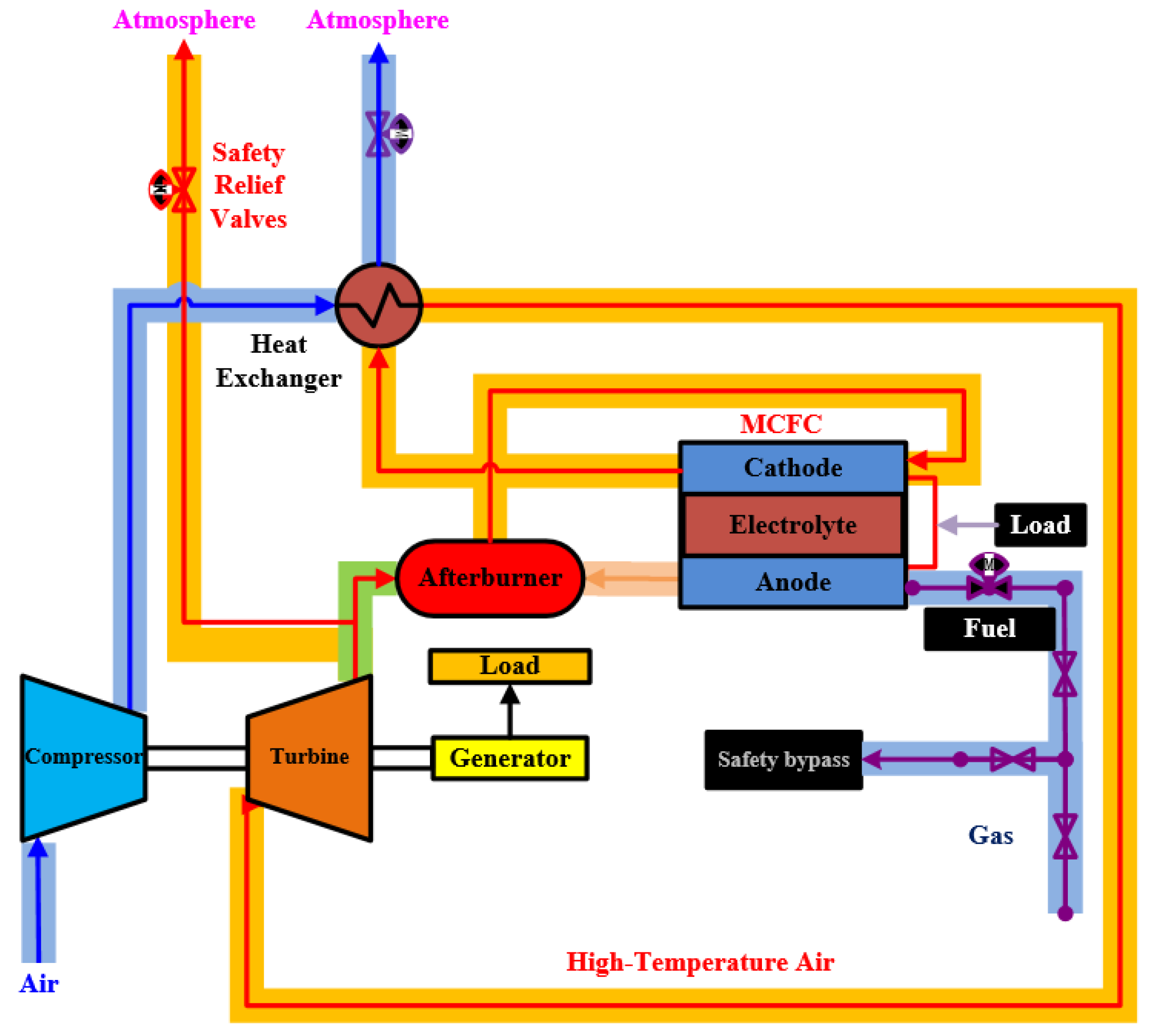
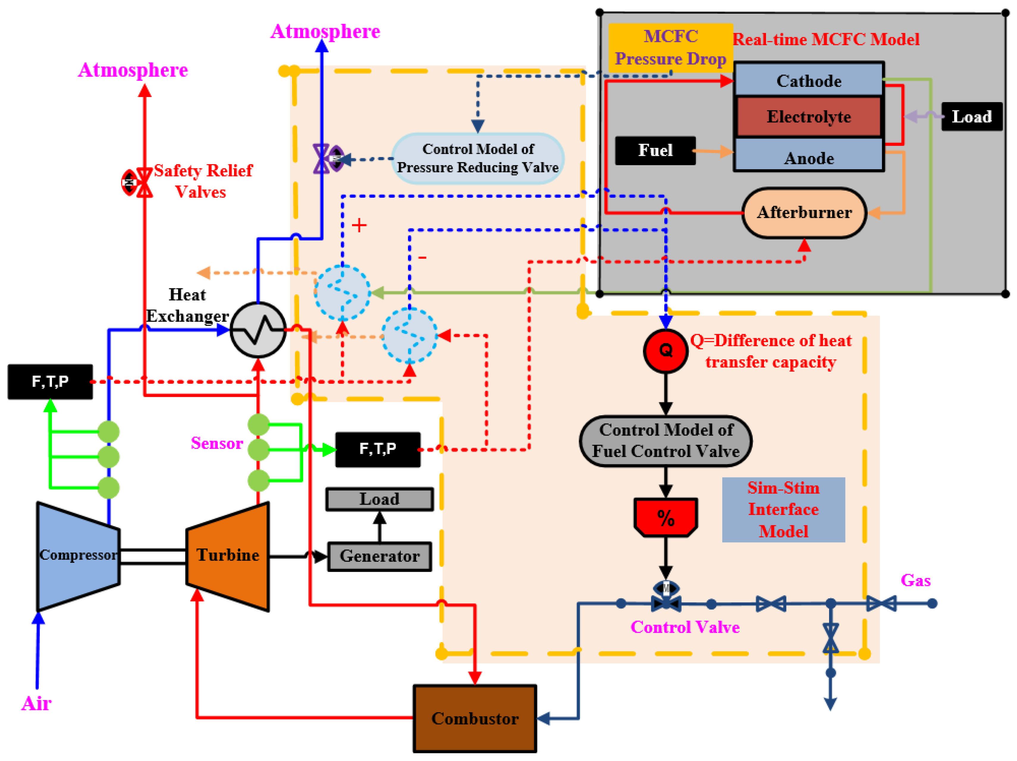
The direct reforming MCFC-MGT hybrid power system is shown in Figure 1. Air is pressurized by a compressor. Then, the compressed air is delivered to the HE to recover waste heat released by the MCFC. Next, the heated air expands in the turbine that coaxially drives the compressor and the generator. The exhaust gas from the turbine flows into the oxidizer, in which an oxidation reaction occurs with the remaining fuel that escapes from the MCFC anode outlet. Then, the gas that contains abundant carbon dioxide goes into the cathode channel of the MCFC. The advantages of this hybrid power system are that the operating pressure of MCFC is almost equal with the atmospheric pressure and the waste heat of the MCFC is sufficiently used by the MGT. A diagram of the MCFC-MGT HILS system is shown in Figure 2. The components inside the solid line are the virtual parts of the HILS system, the components inside the dotted line are the interface parts, and the others are the physical parts. In the physical part of the MCFC-MGT HILS system, the real MCFC stack between the turbine and the HE is absent. Therefore, the gas flowing into the HE is not heated by the MCFC stack, and the pressure loss of the MCFC that has an effect on the characteristics of the MGT is missed. In order to solve this two main problem, a new Sim–Stim interface model for the MCFC-MGT HILS hybrid power system that includes a model to calculate energy compensation, a model to calculate pressure compensation, and the actual actuator was proposed.
Firstly, in order to guarantee energy conservation on the cold side of the HE, the enthalpy difference of the HE outlet between the two different HE models is calculated. The entrance boundary conditions of one HE model are obtained by measuring the temperature, pressure, and mass flow of the compressor outlet and the turbine outlet. The entrance boundary conditions of the another one are gained from the output of the MCFC stack and the measured value of the turbine outlet. Then, the enthalpy difference of the heated air is compensated by injecting additional fuel into the combustor of the MGT. The enthalpy difference is converted to the fuel mass flow rate by dividing the Low Calorific Value (LCV) of the fuel. Then, feed-forward and Proportion Integration Differentiation (PID) technology are employed to achieve fast and accurate control of the fuel valve. A schematic diagram of the afterburning control structure is shown in Figure 3. The mass flow rate of the additional fuel is much smaller than the air entering the turbine, and the effect of the mass flow change is ignored. In addition, because of the huge thermal inertia of the MCFC stack, the temperature of the cathode outlet changes slowly. The flow delay, which exists between the turbine and the HE, is neglected. Secondly, due to missing the pressure loss of the MCFC stack between the turbine and the HE, the dynamic characteristics of the turbine change as the backpressure varies. Although the actual MCFC stack should be located between the HE and the turbine, the pressure control valve at the end of the MGT, which simulates the pressure drop of the MCFC stack, does not affect the turbine’s operating characteristics due to the rapid pressure propagation. Therefore, the mass conservation, energy conservation, and momentum conservation between the MCFC-MGT system and the MCFC-MGT HILS system can be achieved by building the Sim–Stim interface model and applying it in the hybrid power system, which includes the measurement equipment, the models of the two kinds of HEs, the model of the pressure drop in the MCFC stack, the fuel control valve, and the pressure control valve.
Hence, ensuring the balance of mass, energy, and momentum between the virtual part and the physical part of the HILS system can achieve reasonable dynamic characteristics in the HILS system. In order to validate the Sim–Stim interface model before the actual application, real-time models of both the MCFC-MGT system and the MCFC-MGT HILS system are developed in this paper. The MGT is simulated by Advanced PROcess Simulation (APROS), which is mainly based on modularization and supports the external module developed by the user. The model of MCFC and the model of the Sim–Stim interface model are simulated by the Dynamic Link Library (DLL) using Fortran language. The model of the MCFC stack is a lumped real-time model embedded in APROS. The developed MCFC stack module is illustrated in Figure 4.
2.2. Mathematical Model
2.2.1. Basic Equations
The lumped parameter method is employed to develop the model of the MCFC-MGT hybrid power system. Due to no phase change occurring in all components of the hybrid power system, the homogeneous model is enough to simulate the conservation of the gas flow. It mainly includes the following three conservation equations [30]:
Mass balance:
Momentum balance:
Energy balance:
In the above equations, is the quantity of heat exchange, is the friction force produced during gas flow, and the subscript is the wall of the pipe or other components. To solve the partial differential equations, the discretization methods of time and space are utilized. The staggered discretization scheme is used for spatial discretization. Different parameters are solved at different locations in the grid. At the same time, the implicit method is considered for the temporal discretization [30].
2.2.2. Compressor Model
The ideal process for a compressor is an isentropic compression process. However, the thermal process inside the compressor is affected by multiple elements, such as frictional heat generation. Calculation of the compression process requires correction of the isentropic process. The adiabatic efficiency is the power consumption ratio of the adiabatic isentropic process to the adiabatic entropy increase process.
The power consumption of the ideal process of the compression is a function of the temperature, pressure ratio, and specific heat capacity ratio:
where is the ideal gas constant. Therefore, the temperature of the compressor exit is calculated as follows [31]:
where is the pressure ratio of the compressor.
2.2.3. Turbine Model
The calculation of pressure and enthalpy is employed to simulate the turbine. The flow rate is a function of the pressure between the inlet and outlet of the turbine. In the turbine, there are different outlet pressures under different flows. Therefore, the Stodola coefficient is calculated as follows [32]:
where is the Stodola coefficient, is the mass flow rate through the turbine model, and and are the model inlet and outlet pressure, respectively; is the model inlet specific volume. The subscript represents parameters under ideal conditions. The above formula shows that if the inlet and outlet pressure are known, the mass flow rate through the model can also be obtained:
The practical form loss factor is calculated as follows:
For the gas turbine, the working fluid is gas. The model enthalpy difference is
2.2.4. MCFC Model
In this paper, the direct reforming MCFC is considered. The reforming reaction of methane is an endothermic reaction, and is thus affected by the temperature. The gas species of the anode and cathode also impact the chemical reactions. For convenience, collection of the gas species is arranged in the following order:
To reflect the main characteristics of the fuel cell and simplify the model, the four main reactions, including the anode electrochemical reaction, the reforming reaction, the water-gas shift reaction, and the cathode electrochemical reaction, are considered:
The reforming reaction rate is determined by the temperature, pressure, and gas species in the anode channel [33].
where is the reaction constant, and is the equilibrium constant of the reforming reaction [33].
is a function of the partial pressure of gas species and the gas adsorption constant:
The water-gas shift reaction is a reversible reaction, where the equilibrium constant is a function of the gas species [25]:
Then, a lumped parameter model is applied to solve the transient process of the fuel cell. Some assumptions are considered in the simplified model:
- All the gases are ideal gases;
- The temperature of the fuel cell is equal with the temperature of cathode exit and anode exit;
- The energy storage of gas and the heat exchange with the atmosphere are ignored;
- The average feature of the gases is consistent with the exit feature.
The mass balance equations of the anode and cathode are as follows [25]:
where is the control volume of the channel, is the mole quality per unit volume, is the mole flow rate, is mole percentage, and is the total reaction rate of all reactions. The subscripts represent the anode and cathode, respectively; represents seven different species, and represent the inlet and outlet of the channel, respectively.
The energy balance equation of the fuel cell is shown as follows:
where is the enthalpy of the gas, is the mass of the fuel cell, and is the power generated by the fuel cell. After the gas species and the temperature of the stack are solved, the voltage of the cell and the stack can be calculated by the Nernst equation and polarization loss [34]:
The Nernst voltage [35] is calculated by
For this model, by fitting the equation of standard change in Gibbs energy for the water formation reaction, the equation of as the temperature function was established. The equation for the standard potential voltage [34] is
The internal resistance of the fuel cell is provided by the literature [34]:
The polarization resistance of the anode and cathode is complicated, which can be calculated from some correlation equations [34]:
2.2.5. Heat Exchanger Model
The HE is simulated by a lumped parameter model. The HE internal working fluid of the cold side and heat side are air and flue gas, respectively. Therefore, the universal fluid heat transfer equations for the compressible fluid are applied to build the model of the HE:
In the above equations, is the flow rate, is the enthalpy, the subscripts represent the hot side and cold side, respectively; is the energy transfer from the gas of the hot side to the wall, is the energy transferring from the wall to the gas of the cold side:
In the HE, the thermal inertia of the metal wall cannot be ignored. The heat transferring to the metal wall and the heat transferring from the metal wall cannot be immediately balanced during changing conditions. The heat difference will change the wall temperature:
where are the specific heat and mass of the metal wall, respectively.
3. Model Validation
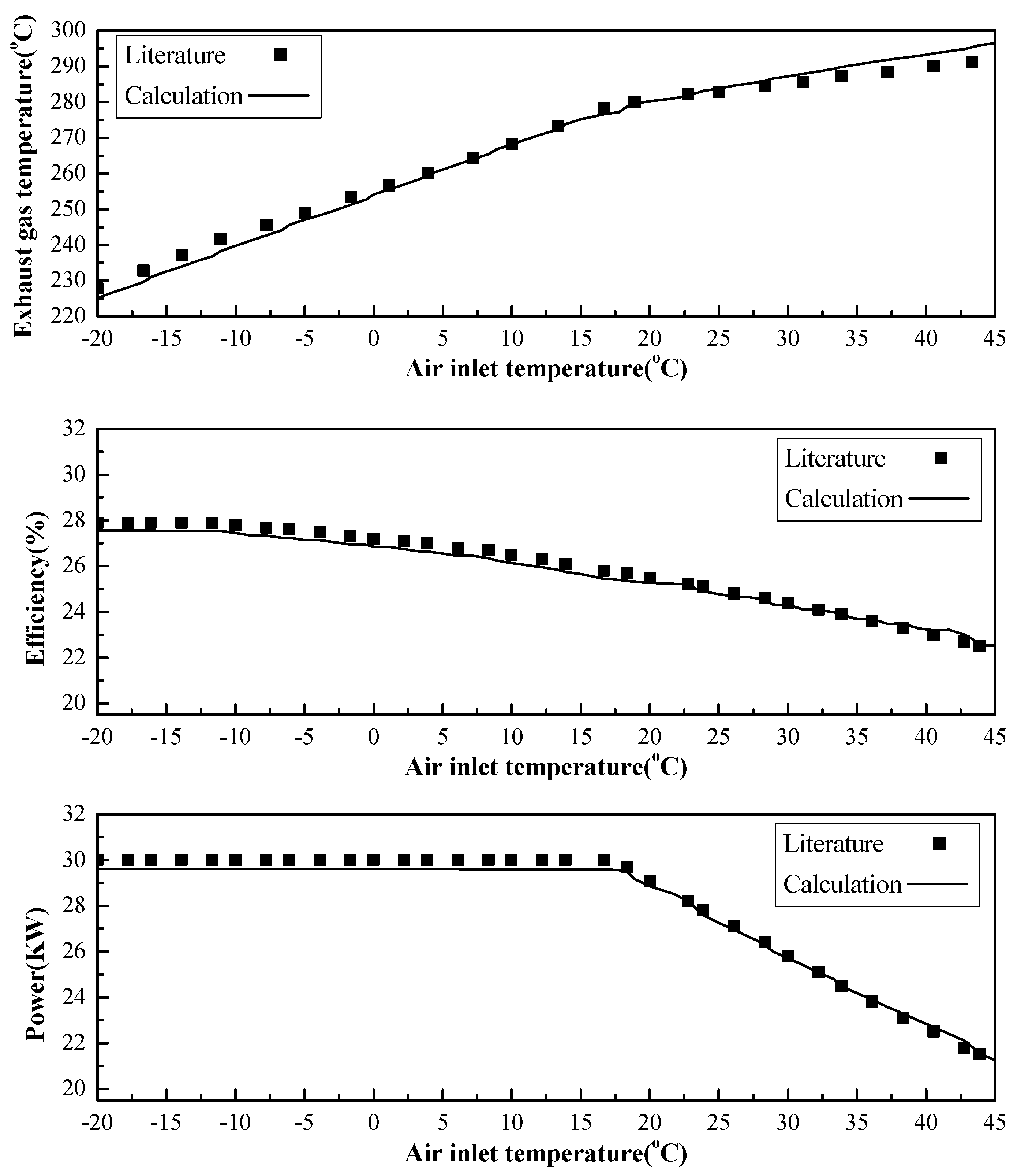
The MGT model was simulated by APROS, which was developed by VTT Finland. The model of the MCFC embedded in APROS was developed by the Dynamic Link Library (DLL) using Fortran language. The hybrid simulation method was utilized to simulate the MCFC-MGT hybrid power system. To evaluate the model of the MGT, the steady-state parameters under rated conditions and the steady-state parameters at different atmospheric temperatures were compared with design values [24]. The boundary conditions of the MGT are shown in Table 1. The steady-state comparison between the design values and the simulation results under rated conditions is shown in Table 2. The maximum relative error was 3.01%, which occurred at the compressor outlet temperature. However, the absolute error was 4.6 °C, which is reasonable for the simulation. As shown in Figure 5, at air inlet temperatures ranging from −20 °C to 45 °C, the steady-state parameters, including the exhaust gas temperature, the output power, and the efficiency, were compared with the design parameters. The maximum output power of C30 was limited to 30 kW. The power was maintained at 30 kW by adjusting the fuel mass flow when the ambient temperature was low. As the ambient temperature increased, the mass flow of compressed air decreased and the gas flow of the turbine intake decreased. In order to keep output power at 30 kW, it was necessary to increase the inlet temperature of turbine. However, when the ambient temperature increased by more than 17 °C, increasing the fuel mass flow would have cause the turbine inlet to overheat. In order to protect the MGT, when the ambient temperature exceeded 17 °C, the MGT output power began to decrease as the ambient temperature increased. The comparison of the simulation results with the design values of the MGT shows a good agreement, as shown in Figure 5.
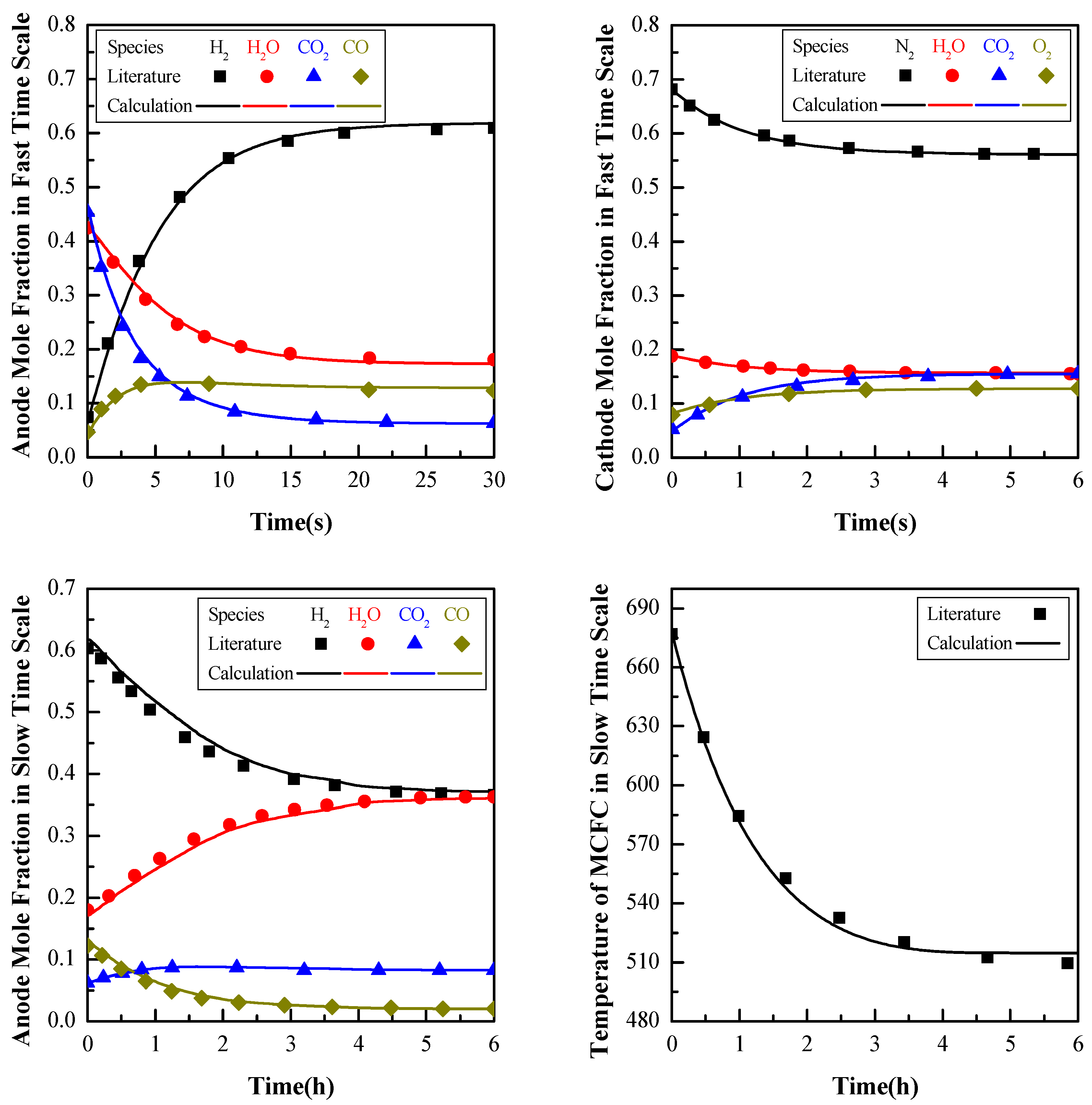
The designed and physical parameters of the MCFC are based on the literature [25]. Thus, the MCFC parameters were compared with those in the literature [25], as shown in Table 3. The current density of the MCFC is a given condition that is 1600 A/m2. The simulation results of the power of the MCFC stacks and the mole friction of the MCFC exit were highly consistent with the literature. To validate the dynamic characteristics of the MCFC model, a current density trip at full load was implemented. When the current density was rapidly removed, the electrochemical reaction suddenly disappeared. As shown in Figure 6, the transient responses of the MCFC model were validated with the literature [25]. In the anode channel, the mole fractions of steam and carbon dioxide decreased quickly, and the mole fraction of hydrogen increased quickly. The equilibrium constant of the water-gas shift reaction is a function of the MCFC temperature that almost stays constant over a short period of time. Due to changes in steam, carbon dioxide, and hydrogen, the carbon monoxide affected by the reverse movement of the water-gas shift reaction increases quickly. Since the electrochemical reaction disappears, a greater fraction of the gas species in the cathode channel remains unchanged after a rapid change. Moreover, the rate of change is related to the volume of the cathode channel. The electrochemical reaction is an exothermic reaction. Because the electrochemical reaction disappears, the temperature of the gas in the cathode channel decreases rapidly. However, the temperature of the MCFC stack slowly decreases under the influence of thermal inertia. The reforming reaction and the displacement reaction change slowly with temperature. Therefore, the gas composition in the anode channel also changes slowly. The comparison with the literature showed that the dynamic characteristics of the MCFC model are highly consistent with the literature. Consequently, the proven MCFC model, which changed the number of fuel cells, was coupled with the verified MGT model to simulate the MCFC-MGT hybrid system, in which the output powers of MGT and MCFC were 16.1 and 145.3 kW, respectively.
4. Simulation Results and Discussion
In order to validate the real-time Sim–Stim interface model, real-time models of the direct reforming MCFC-MGT hybrid power system and the direct reforming MCFC-MGT hybrid power system based on the Sim–Stim interface model were developed in the APROS platform. Because the mature Capstone C30 MGT is employed in the actual MCFC-MGT HILS system, the original control of the C30 is preserved. Its rotational speed remains constant within the controllable range during the study of the dynamic characteristics of HILS system. Therefore, the step change of the MCFC current density is a strict test for the Sim–Stim interface model under all conditions. Therefore, the step-down and step-up of the MCFC current density were simulated during a real-time operation and compared to the models of the MCFC-MGT hybrid power system and the MCFC-MGT hybrid power system based on the Sim–Stim interface model. For convenience, the model of the MGT-MCFC hybrid power system is named Model A, and the model of the MCFC-MGT based on Sim–Stim interface model is named Model B. In order to confirm the effectiveness of the Sim–Stim interface model, the slow time scale and the fast time scale of the main dynamic parameters were observed.
4.1. The Step-Down of the MCFC Current Density
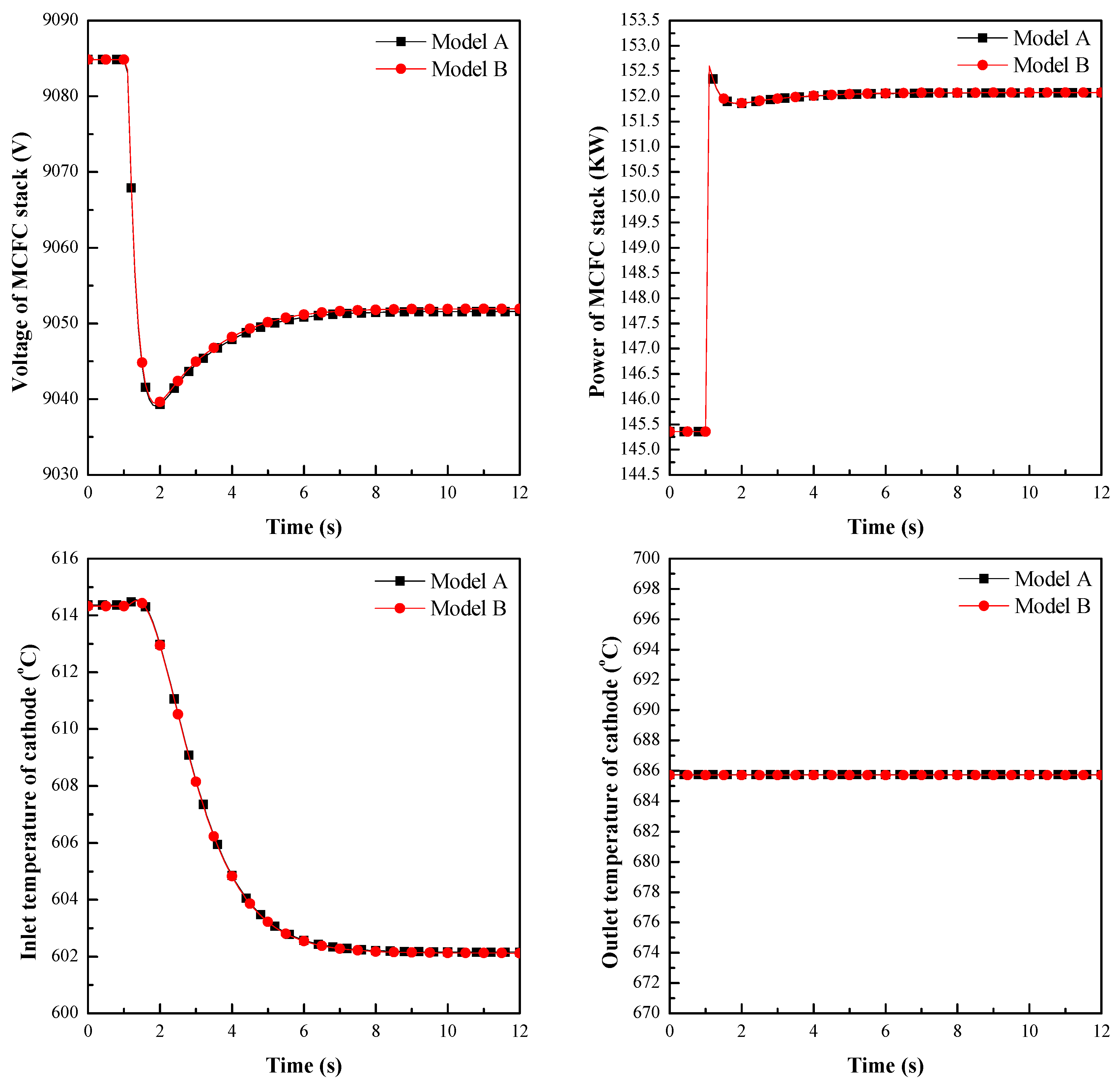
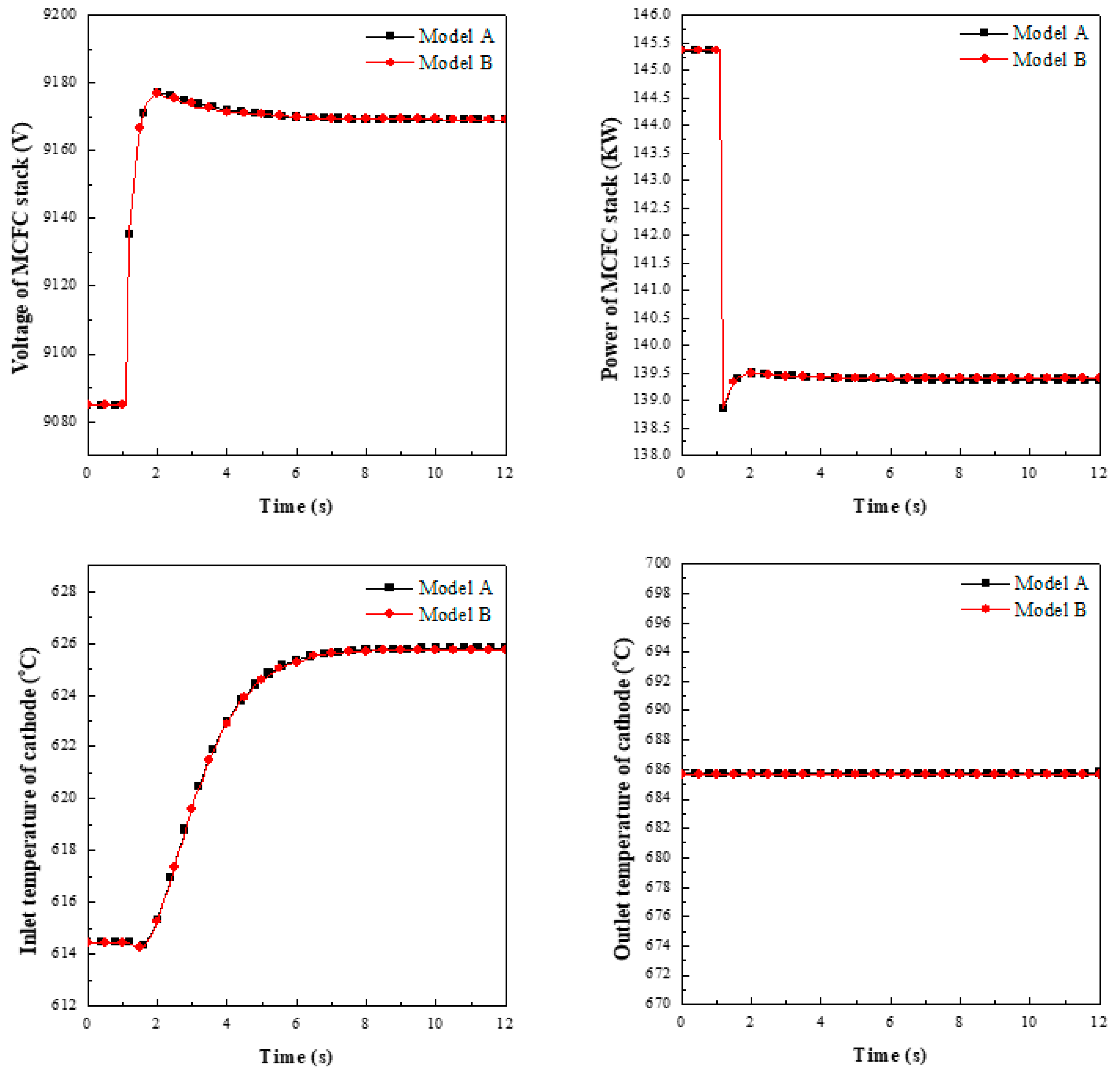
For the fast time scale simulation with step-down of the MCFC current density, the transient response of the voltage of the MCFC, the power of the fuel cell stacks, the cathode inlet temperature, and the cathode outlet temperature were investigated. The comparison between the MCFC-MGT model and the MCFC-MGT model based on the Sim–Stim interface model are presented in Figure 7. When the MCFC current density steeply decreased by 5%, the power of the MCFC stacks, which is a function of current density, rapidly decreased by 5%. Shortly afterwards, under the combined effect of the change in the remaining fuel composition and current density, the voltage of the MCFC stacks increased by about 0.9% in 1 second. The power of the MCFC stack also increased by about 0.9%. Hence, the power of the MCFC stack decreasesd by 4.1%, and the fuel utilization of the MCFC stack decreased. The incremental resident fuel reacted in the combustor, and the flue gas entered the cathode channel of the MCFC. Therefore, the cathode inlet temperature of the MCFC increased. However, when the thermal inertia of the MCFC stack was greater than the thermal inertia of the gas, the cathode outlet temperature of the MCFC was almost stable over a short period of time. Therefore, the negligence of the flow delay existing between the turbine and the HE is reasonable. The comparison between the MCFC-MGT model and the MCFC-MGT model based on the Sim–Stim interface model revealed that the fast time scale dynamic response is identical and the Sim–Stim interface model is rapid.
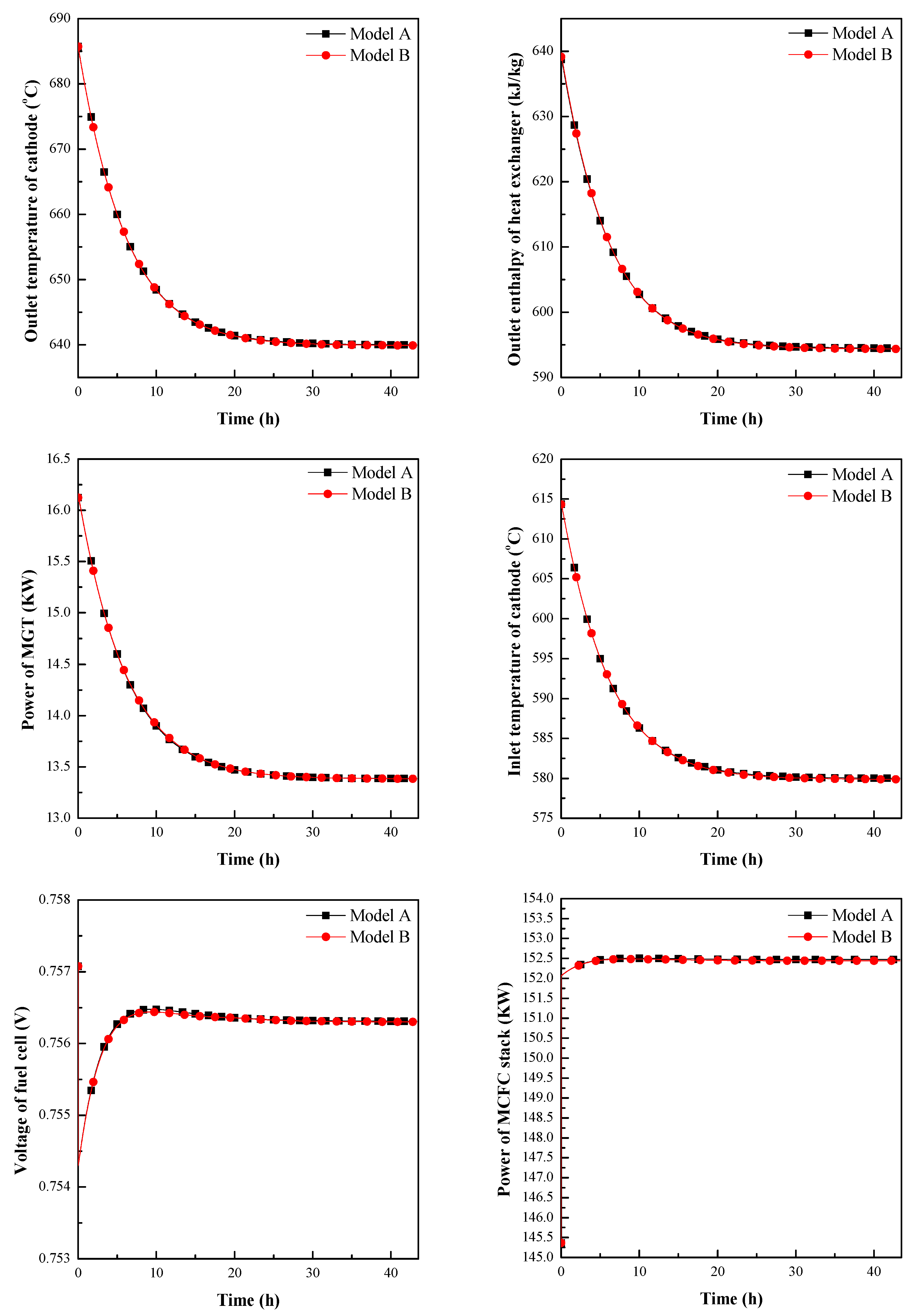
For the slow time scale simulation with step-down of the MCFC current density, the outlet temperature of the cathode, the outlet enthalpy of the HE, the power of MGT, the inlet temperature of the cathode, the voltage of the fuel cell, and the power of the MCFC stack were observed. The comparison of dynamic responses between the MCFC-MGT model and the MCFC-MGT model based on the Sim–Stim interface model is shown in Figure 8. Because the thermal inertia of the MCFC stack is huge, the cathode outlet temperature changed slowly in the slow time scale simulation. Moreover, due to the interaction between the MGT and the MCFC, the time constant of the temperature of the MCFC stack increased further. As shown in Figure 7, when the current density changed to step-down, the cathode inlet temperature increased quickly. As shown in Figure 8, the temperature of the cathode outlet gradually increased. Since the exhaust of cathode flows into the heat side of the HE, the outlet enthalpy of the HE rose slowly. Then, with the increase in internal energy of heated gas, the power of the MGT and the outlet temperature of the turbine increased. The inlet temperature of the MCFC cathode also increased as the outlet temperature of the turbine increased. The relationship between the voltage of the fuel cell and the temperature of the fuel cell is complicated. The voltage of the fuel cell also varied with the temperature of the fuel cell. The power of the MCFC stack changed slowly as the voltage of the fuel cell varied. The transient characteristic comparison between the MCFC-MGT model and MCFC-MGT model based on the Sim–Stim interface model showed a good agreement in the slow time scale after the current density step-down change.
4.2. The Step-Up of the MCFC Current Density
For the fast time scale simulation with step-up of the MCFC current density, the transient response of the voltage of the MCFC, the power of the fuel cell stacks, the cathode inlet temperature, and the cathode outlet temperature were investigated. The fast time scale transient response of the MCFC-MGT hybrid power system during the MCFC current density step-up process is almost opposite to the step-down process. Therefore, the comparison between the MCFC-MGT model and the MCFC-MGT model based on the Sim–Stim interface model is presented in Appendix A. The accordant transient response between the MCFC-MGT model and the MCFC-MGT model based on the Sim–Stim interface model demonstrated that the Sim–Stim interface model is rapid and reasonable.
A comparison of the dynamic characteristics following the MCFC current density step-up change between the MCFC-MGT model and MCFC-MGT model based on the Sim–Stim interface model at a slow time scale, including the outlet temperature of the cathode, the outlet enthalpy of the HE, the power of the MGT, the inlet temperature of the cathode, the voltage of the fuel cell, and the power of the MCFC stacks, are presented in Figure 9. The outlet temperature of the cathode descended gradually. The voltage of the fuel cell and the power of the MCFC stacks varied with the temperature of the fuel cell. The gas from the cathode outlet of the MCFC flowed through the heat side of the HE to transfer heat to the compressed air on the cold side. Therefore, the enthalpy of heated air of the HE decreased slowly, resulting in a reduction in the working ability of the heated air. Of course, the outlet temperature of the turbine decreased gradually. Then, the inlet temperature of the MCFC cathode also slowly reduced. When the time was about 10 h, the maximum relative error was 0.05%, which occurred on the voltage of the fuel cell between the MCFC-MGT model and the MCFC-MGT model based on the Sim–Stim interface model. The transient characteristics of the MCFC-MGT model and MCFC-MGT model based on Sim–Stim interface model showed a good agreement in the slow time scale after the current density step-up changed. Thus, the accordant dynamic characteristics between the MCFC-MGT model and the MCFC-MGT model based on the Sim–Stim interface model demonstrated that the Sim–Stim interface model developed for MCFC-MGT HILS hybrid power system was able to ensure the mass conservation, energy conservation, and momentum conservation between the HILS system and the prototype system.
5. Conclusions
In this work, a real-time model of the direct reforming MCFC-MGT hybrid power system and the direct reforming MCFC-MGT hybrid power system based on the Sim–Stim interface model were developed. The MGT model and the MCFC model were verified, respectively. In addition, by implementing the step-down and step-up of the MCFC current density, the fast transient response of the MCFC-MGT model and the MCFC-MGT model based on the Sim–Stim interface model were compared. The results demonstrate that the real-time Sim–Stim interface model with feed-forward and PID technology is fast and accurate, and the negligence of the flow delay existing between the turbine and the HE is reasonable. Through the step-up and step-down of the MCFC current density, a comparison of the slow time scale transient responses of these two kinds of models were presented to investigate the long-term effectiveness of the Sim–Stim interface model. Research on the step process demonstrates that the real-time Sim–Stim interface model for the MCFC-MGT HILS system is reasonable. Further, the new Sim–Stim interface model will be used in the MCFC-MGT HILS hybrid power system. It establishes a foundation for the development of the HILS method to study the coupled distributed power system with mass, energy, and momentum transfer between subsystems.
Author Contributions
Data curation, K.Y.; Formal analysis, C.Y. and H.H.; Investigation, K.D.; Methodology, K.D. and H.W.; Software, Y.F.; Validation, K.D.; Visualization, C.Y.; Writing—original draft, K.D.; Writing—review & editing, C.Y.
Funding
The authors gratefully acknowledge the friendly support of the National Nature Science Foundation of China (No. 51576020) and Graduate Research and Innovation Foundation of Chongqing, China (No. CYB18052).
Conflicts of Interest
The authors declare no conflict of interest.
Nomenclature
| density (kg/m3) | N2 | nitrogen (-) | |
| velocity (m/s) | p | pressure (Pa) | |
| specific volume (m3/kg) | Pdc | output power of fuel cell stack (W) | |
| specific heat capacity ratio (-) | qc | heat exchange of cool side (W) | |
| pressure ratio (-) | qh | heat exchange of hot side (W) | |
| adiabatic efficiency (-) | Qw | heat flow (W) | |
| Ac | heat exchange area of the cool side (m2) | r1 | reforming reaction rate (mol/s) |
| Ah | heat exchange area of the hot side (m2) | ra | polarization resistance of the anode (Ω) |
| C | mole quality per unit volume (mol/m3) | rc | polarization resistance of the cathode (Ω) |
| CH4 | methane (-) | rohm | internal resistance of the fuel cell (Ω) |
| CO | carbon monoxide (-) | R | ideal gas constant (8.314 J/mol·K) |
| CO2 | carbon dioxide (-) | Ra(c),i | reaction rate of all reactions (mol/s) |
| Cpm | specific heat capacity of metal (J/(kg·K)) | t | time (s) |
| Cps | specific heat capacity of the fuel cell stack (J/(kg·K)) | T | temperature (K) |
| DEN | defined parameter (-) | Ts | fuel cell stack temperature (K) |
| E | Nernst equation (V) | V | control volume of the channel (m3) |
| E0 | standard potential voltage (V) | Vcell | voltage of the fuel cell (V) |
| F | faraday constant (C/mol) | wc | power consumption of the adiabatic entropy increase process (kW) |
| Fa,c | mole flow rate (mol/s) | wc,s | power consumption of the adiabatic isentropic process (kW) |
| Fw | friction force (N) | x | mole fraction (-) |
| g | standard gravity (9.81 m/s2) | Z | elevation (m) |
| GAS | collection of all gases (-) | ||
| h | specific enthalpy (kJ/kg) | Subscripts | |
| H2 | hydrogen (-) | w | wall |
| H2O | water vapor (-) | 0 | ideal conditions |
| J | current density (A/m2) | a | anode |
| k | practical form loss factor (-) | c | cathode |
| k1 | reaction constant of the reforming reaction (-) | i | seven different gas species |
| K | Stodola coefficient | s | fuel cell stack |
| KCH4 | gas adsorption constant of methane (-) | hot | hot side |
| KCO | gas adsorption constant of carbon monoxide (-) | cl | cool side |
| KH2 | gas adsorption constant of hydrogen (-) | m | metal |
| KH2O | gas adsorption constant of steam (-) | ||
| Kp1 | equilibrium constant of the reforming reaction (-) | Superscripts | |
| Kshift | equilibrium constant of water-gas shift reaction (-) | in | inlet |
| m | mass flow (kg/s) | o | outlet |
| Mm | mass of metal (kg) | r | reaction |
| Ms | mass of the fuel cell stack (kg) | ||
Appendix A
Figure A1.
The step-up of MCFC current density—comparison of the fast time scale transient responses of the cell voltage, the fuel cell stack power, the inlet temperature of the cathode, and the outlet temperature of the cathode between the MCFC-MGT model and the MCFC-MGT model based on the Sim–Stim interface model.
References
- Milewski, J.; Discepoli, G.; Desideri, U. Modeling the performance of MCFC for various fuel and oxidant compositions. Int. J. Hydrogen Energy 2014, 39, 11713–11721. [Google Scholar] [CrossRef]
- Gopisetty, S.; Treffinger, P. Generic Combined Heat and Power (CHP) Model for the Concept Phase of Energy Planning Process. Energies 2017, 10, 11. [Google Scholar] [CrossRef]
- Huang, H.; Li, J.; He, Z.; Zeng, T.; Kobayashi, N.; Kubota, M. Performance Analysis of a MCFC/MGT Hybrid Power System Bi-Fueled by City Gas and Biogas. Energies 2015, 8, 5661–5677. [Google Scholar] [CrossRef] [Green Version]
- Liu, A.; Bing, W.; Wen, Z.; Chen, B.; Weng, Y. Catalytic combustion and system performance assessment of MCFC-MGT hybrid system. Int. J. Hydrogen Energy 2014, 39, 7437–7446. [Google Scholar] [CrossRef]
- Liu, A.; Weng, Y. Performance analysis of a pressurized molten carbonate fuel cell/micro-gas turbine hybrid system. J. Power Sour. 2010, 195, 204–213. [Google Scholar] [CrossRef]
- Veyo, S. Westinghouse Fuel Cell Combined Cycle Systems; Office of Scientific & Technical Information Technical Reports: Pittsburgh, PA, USA, 1996. [Google Scholar]
- Wee, J.-H. Molten carbonate fuel cell and gas turbine hybrid systems as distributed energy resources. Appl. Energy 2011, 88, 4252–4263. [Google Scholar] [CrossRef]
- Lorenzo, G.D.; Fragiacomo, P. A methodology for improving the performance of molten carbonate fuel cell/gas turbine hybrid systems. Int. J. Energy Res. 2012, 36, 96–110. [Google Scholar] [CrossRef]
- Ghezel-Ayagh, H.; Walzak, J.; Junker, S.T.; Patel, D.; Michelson, F.; Adriani, A. DFC/T® Power Plant: From Sub-Megawatt Demonstration to Multi-Megawatt Design. ECS Trans. 2008, 12, 713–717. [Google Scholar]
- Ghezel-Ayagh, H.; Walzak, J.; Patel, D.; Daly, J.; Maru, H.; Sanderson, R.; Livingood, W. State of direct fuel cell/turbine systems development. J. Power Sour. 2005, 152, 219–225. [Google Scholar] [CrossRef]
- Kyrychko, Y.N.; Blyuss, K.B.; Gonzalez-Buelga, A.; Hogan, S.J.; Wagg, D.J. Real-time dynamic substructuring in a coupled oscillator–pendulum system. Proc. R. Soc. A Math. Phys. Eng. Sci. 2006, 462, 1271–1294. [Google Scholar] [CrossRef]
- Hao, H.; Zhang, H.; Weng, S.; Ming, S. Dynamic numerical simulation of a molten carbonate fuel cell. J. Power Sour. 2006, 161, 849–855. [Google Scholar]
- Yang, F.; Zhu, X.-J.; Cao, G.-Y. Temperature control of MCFC based on an affine nonlinear thermal model. J. Power Sour. 2007, 164, 713–720. [Google Scholar] [CrossRef]
- Said, S.B.; Saad, K.B.; Benrejeb, M. HIL simulation approach for a multicellular converter controlled by sliding mode. Int. J. Hydrogen Energy 2017, 42, 12790–12796. [Google Scholar] [CrossRef]
- Haghighatkhah, A.; Banijamali, A.; Pakanen, O.P.; Oivo, M.; Kuvaja, P. Automotive software engineering: A systematic mapping study. J. Syst. Softw. 2017, 128, 25–55. [Google Scholar] [CrossRef]
- Tauzia, X.; Karaky, H.; Maiboom, A. Evaluation of a semi-physical model to predict NOx and soot emissions of a CI automotive engine under warm-up like conditions. Appl. Therm. Eng. 2018, 137, 521–531. [Google Scholar] [CrossRef]
- Park, J.I.; Park, H.E.; Park, S.Y.; Choi, K.H. Hardware-in-the-loop simulations of GPS-based navigation and control for satellite formation flying. Adv. Space Res. 2010, 46, 1451–1465. [Google Scholar] [CrossRef]
- Al-Jarrah, M.A.; Hasan, M.M. HILS setup of dynamic flight path planning in 3D environment with flexible mission planning using Ground Station. J. Frankl. Inst. 2011, 348, 45–65. [Google Scholar] [CrossRef]
- Ayasun, S.; Fischl, R.; Vallieu, S.; Braun, J.; Çadırlı, D. Modeling and stability analysis of a simulation–stimulation interface for hardware-in-the-loop applications. Simul. Modell. Pract. Theory 2007, 15, 734–746. [Google Scholar] [CrossRef]
- Lukas, M.D.; Lee, K.Y.; Ghezel-Ayagh, H. An Explicit Dynamic Model for Direct Reforming Carbonate Fuel Cell Stack. IEEE Power Eng. Rev. 2001, 21, 63. [Google Scholar] [CrossRef]
- Roberts, R.A.; Jabbari, F.; Brouwer, J.; Gemmen, R.S.; Liese, E.A. Inter-Laboratory Dynamic Modeling of a Carbonate Fuel Cell for Hybrid Application. In Proceedings of the 2003 International Joint Power Generation Conference, Atlanta, GA, USA, 16–19 June 2003; pp. 565–572. [Google Scholar]
- Law, M.C.; Lee, C.C.; Tay, C.L. Dynamic behaviors of a molten carbonate fuel cell under a sudden shut-down scenario: The effects on temperature gradients. Appl. Therm. Eng. 2015, 82, 98–109. [Google Scholar] [CrossRef]
- Lee, C.-W.; Lee, M.; Yoon, S.-P.; Ham, H.-C.; Choi, S.H.; Han, J.; Nam, S.W.; Yang, D.-Y. Study on the effect of current collector structures on the performance of MCFCs using three-dimensional fluid dynamics analysis. J. Ind. Eng. Chem. 2017, 51, 153–161. [Google Scholar] [CrossRef]
- Corporation, C.T. Technical Reference: Capstone Model C30 Performance; Capstone Turbine Corporation: Chatsworth, CA, USA, 2006. [Google Scholar]
- Lukas, M.D.; Lee, K.Y.; Ghezel-Ayagh, H. Development of a stack simulation model for control study on direct reforming molten carbonate fuel cell power plant. IEEE Trans. Energy Convers. 1999, 14, 1651–1657. [Google Scholar] [CrossRef]
- Jurado, F.; Saenz, J.R. Adaptive control of a fuel cell-microturbine hybrid power plant. In Proceedings of the IEEE Power Engineering Society Summer Meeting, Chicago, IL, USA, 21–25 July 2002; Volume 1, pp. 76–81. [Google Scholar]
- Roberts, R.A.; Brouwer, J.; Liese, E.; Gemmen, R.S. Dynamic simulation of carbonate fuel cell-gas turbine hybrid systems. J. Eng. Gas Turbines Power 2006, 128, 294–301. [Google Scholar] [CrossRef]
- McLarty, D.; Brouwer, J.; Samuelsen, S. Fuel cell–gas turbine hybrid system design part II: Dynamics and control. J. Power Sour. 2014, 254, 126–136. [Google Scholar] [CrossRef]
- Bedont, P.; Grillo, O.; Massardo, A.F. Off-Design Performance Analysis of a Hybrid System Based on an Existing MCFC Stack. J. Eng. Gas Turbines Power 2003, 125, 387–395. [Google Scholar] [CrossRef]
- Siikonen, T. Numerical method for one-dimensional two-phase flow. Numer. Heat Trans. Appl. 1987, 12, 1–18. [Google Scholar]
- Duan, J.; Sun, L.; Wang, G.; Wu, F. Nonlinear modeling of regenerative cycle micro gas turbine. Energy 2015, 91, 168–175. [Google Scholar] [CrossRef]
- Stodola, A. Steam and Gas Turbines; Peter Smith: New York, NY, USA, 1945; Volume 1. [Google Scholar]
- Xu, J.; Froment, G.F. Methane Steam Reforming, Methanation and Water-Gas Shift: I. Intrinsic Kinetics. AiChe J. 1989, 35, 88–96. [Google Scholar] [CrossRef]
- Koh, J.-H.; Seo, H.-K.; Yoo, Y.-S.; Lim, H.C. Consideration of numerical simulation parameters and heat transfer models for a molten carbonate fuel cell stack. Chem. Eng. J. 2002, 87, 367–379. [Google Scholar] [CrossRef]
- Hirschenhofer, J.H.; Stauffer, D.B.; Engleman, R.R.; Klett, M.G. Fuel Cell Handbook; Business/Technology Books: Morgantown, VA, USA, 1998. [Google Scholar]
Figure 1.
Molten Carbonate Fuel Cell-Micro Gas Turbine (MCFC-MGT) hybrid power system diagram.

Figure 2.
Schematic diagram of MCFC-MGT hybrid power system based on the Sim–Stim interface model.

Figure 3.
Schematic diagram of the afterburning control structure.
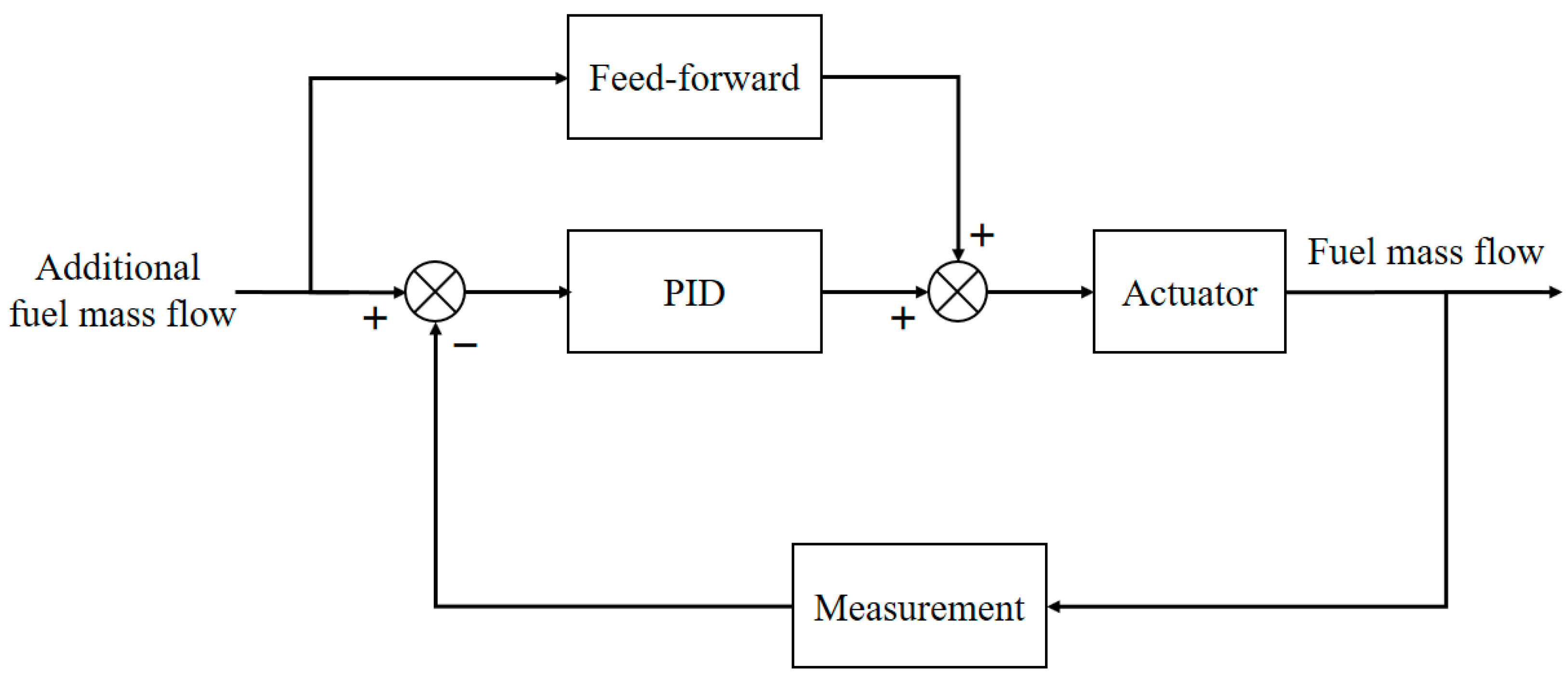
Figure 4.
The MCFC stack module developed in Advanced PROcess Simulation (APROS).
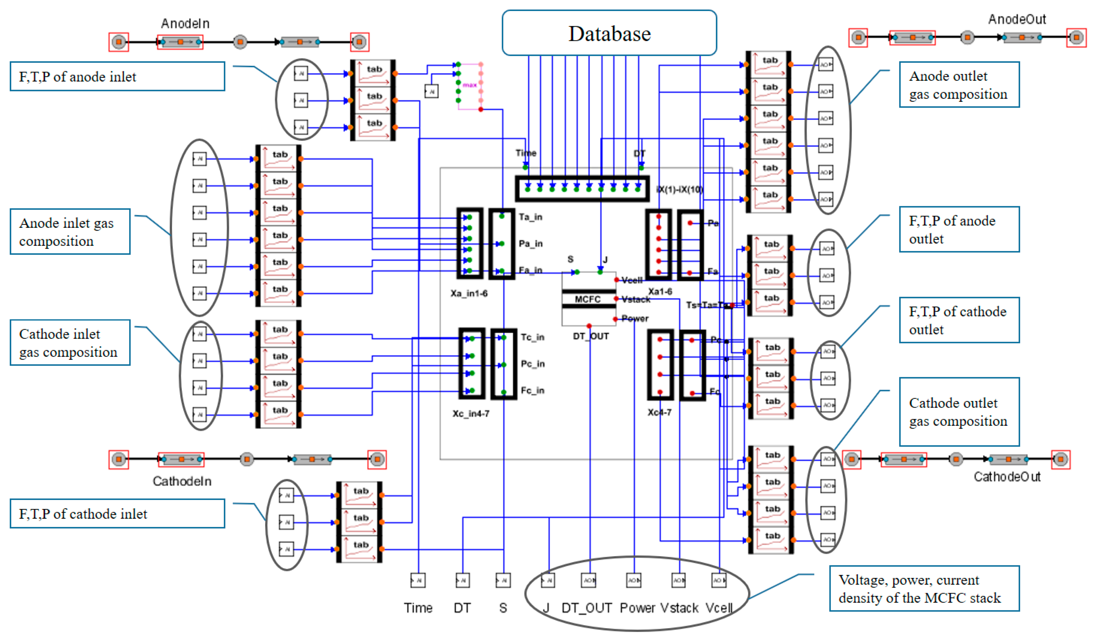
Figure 5.
The exhaust gas temperature, output power, and efficiency comparison between the simulation and design values [24] at air inlet temperatures ranging from −20 °C to 45 °C.
Figure 5.
The exhaust gas temperature, output power, and efficiency comparison between the simulation and design values [24] at air inlet temperatures ranging from −20 °C to 45 °C.

Figure 6.
The step-down of MCFC current density and the transient response of the MCFC stack comparison between the literature and calculation.
Figure 6.
The step-down of MCFC current density and the transient response of the MCFC stack comparison between the literature and calculation.

Figure 7.
The step-down of MCFC current density—comparison of the fast time scale transient responses of the cell voltage, the fuel cell stack power, the inlet temperature of the cathode, and the outlet temperature of the cathode between the MCFC-MGT model and the MCFC-MGT model based on the Sim–Stim interface model.

Figure 8.
The step-down of the MCFC current density—comparison of the slow time scale transient responses of the outlet temperature of the cathode, the outlet enthalpy of the heat exchanger, the power of the MGT, the inlet temperature of the cathode, the voltage of the fuel cell, and the power of the MCFC stack between the MCFC-MGT model and the MCFC-MGT model based on the Sim–Stim interface model.
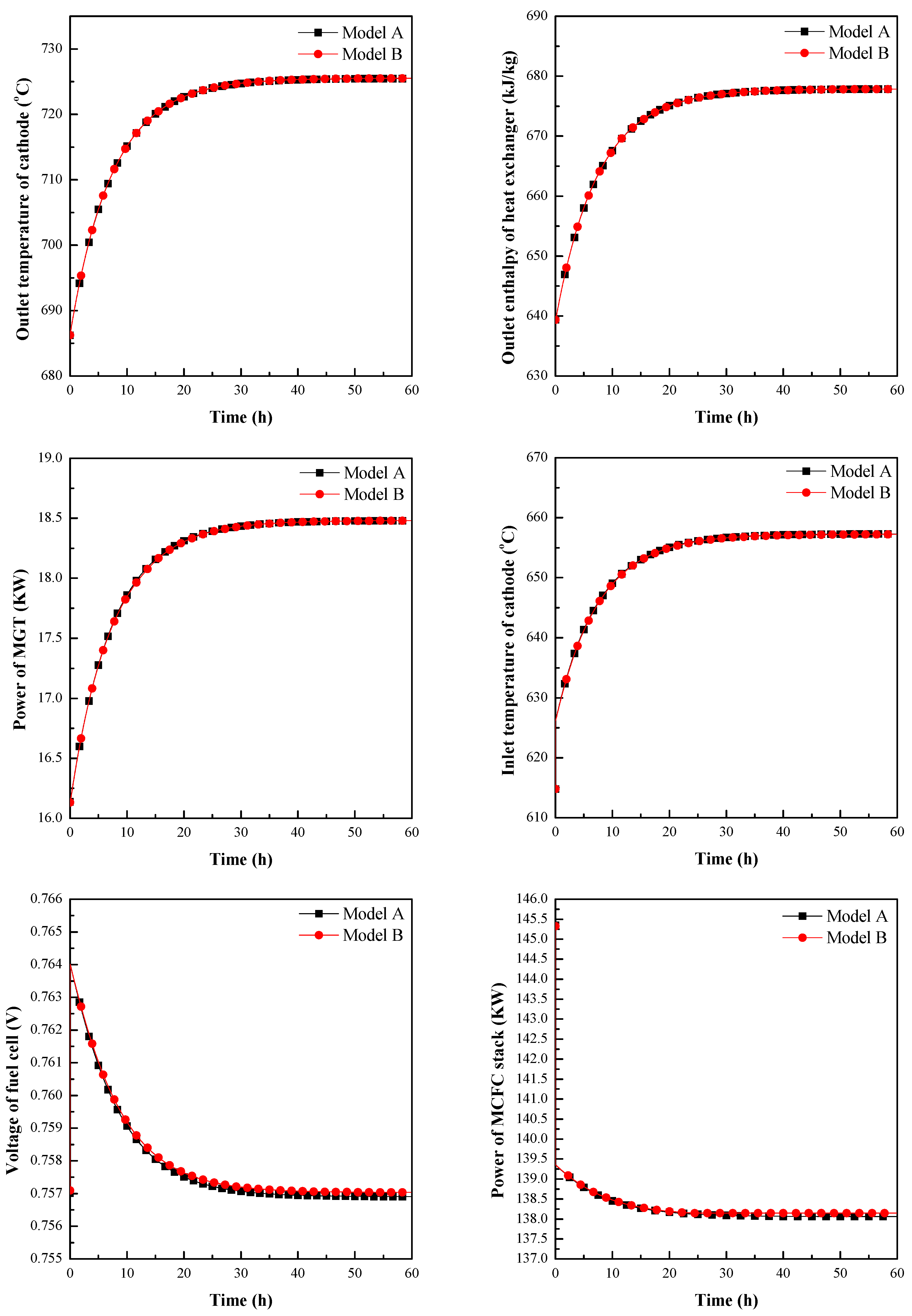
Figure 9.
The step-up of the MCFC current density—comparison of the slow time scale transient response of the outlet temperature of the cathode, the outlet enthalpy of the heat exchanger, the power of the MGT, the inlet temperature of the cathode, the voltage of the fuel cell, and the power of the MCFC stack between the MCFC-MGT model and the MCFC-MGT model based on the Sim–Stim interface model.

Table 1.
The boundary conditions of MGT.
| Parameter | Value | Unit |
|---|---|---|
| Compressor inlet temperature | 15 | °C |
| Compressor inlet pressure | 0.97 | bar |
| Fuel inlet temperature | 25 | °C |
| Fuel inlet pressure | 3.57 | bar |
Table 2.
Comparison of the MGT parameters between the design value [24] and the simulation result.
Table 2.
Comparison of the MGT parameters between the design value [24] and the simulation result.
| Parameter | Simulation Result | Design Value | Unit | Relative Error |
|---|---|---|---|---|
| Compressor outlet temperature | 157.6 | 153 | °C | 3.01% |
| Compressor outlet pressure | 3.1 | 3.1 | bar | 0.00% |
| Compressor flow rate | 0.31 | 0.31 | kg/s | 0.00% |
| Fuel inlet flow rate | 0.0024 | 0.0024 | kg/s | 0.00% |
| Combustor outlet temperature | 822.2 | 840 | °C | −2.12% |
| Combustor outlet pressure | 2.89 | 2.89 | bar | 0.00% |
| Turbine inlet temperature | 822.2 | 840 | °C | −2.12% |
| Turbine outlet temperature | 615 | 620 | °C | −0.81% |
| Power | 29.63 | 30 | MW | −1.23% |
Table 3.
Comparison of the MCFC parameters between the literature [25] and the simulation results.
Table 3.
Comparison of the MCFC parameters between the literature [25] and the simulation results.
| Parameter | Simulation Result | Literature | Unit | Relative Error |
|---|---|---|---|---|
| Gross DC Power | 2294 | 2295 | kW | −0.04% |
| The Temperature of Stack | 676.99 | 677.00 | °C | 0.00% |
| Mole Friction of CH4 at the Anode Exit | 0.001089 | 0.0011 | / | −1.00% |
| Mole Friction of CO at the Anode Exit | 0.046112 | 0.0462 | / | −0.19% |
| Mole Friction of H2 at the Anode Exit | 0.074027 | 0.0741 | / | −0.10% |
| Mole Friction of CO2 at the Anode Exit | 0.453903 | 0.4533 | / | 0.13% |
| Mole Friction of H2O at the Anode Exit | 0.428700 | 0.4245 | / | 0.99% |
| Mole Friction of CO2 at the Cathode Exit | 0.047637 | 0.0476 | / | 0.08% |
| Mole Friction of H2O at the Cathode Exit | 0.187948 | 0.1880 | / | −0.03% |
| Mole Friction of N2 at the Cathode Exit | 0.676758 | 0.6778 | / | −0.15% |
| Mole Friction of O2 at the Cathode Exit | 0.087658 | 0.0865 | / | 1.34% |
© 2019 by the authors. Licensee MDPI, Basel, Switzerland. This article is an open access article distributed under the terms and conditions of the Creative Commons Attribution (CC BY) license (http://creativecommons.org/licenses/by/4.0/).
Share and Cite
MDPI and ACS Style
Yang, C.; Deng, K.; He, H.; Wu, H.; Yao, K.; Fan, Y. Real-Time Interface Model Investigation for MCFC-MGT HILS Hybrid Power System. Energies 2019, 12, 2192. https://doi.org/10.3390/en12112192
AMA Style
Yang C, Deng K, He H, Wu H, Yao K, Fan Y. Real-Time Interface Model Investigation for MCFC-MGT HILS Hybrid Power System. Energies. 2019; 12(11):2192. https://doi.org/10.3390/en12112192
Chicago/Turabian StyleYang, Chen, Kangjie Deng, Hangxing He, Haochuang Wu, Kai Yao, and Yuanzhe Fan. 2019. "Real-Time Interface Model Investigation for MCFC-MGT HILS Hybrid Power System" Energies 12, no. 11: 2192. https://doi.org/10.3390/en12112192
Note that from the first issue of 2016, this journal uses article numbers instead of page numbers. See further details here.