Article

An Intelligent Battery Energy Storage-Based Controller for Power Quality Improvement in Microgrids

1
Electrical Engineering Department, King Fahd University of Petroleum and Minerals, Dhahran 31261, Saudi Arabia
2
Researcher at K.A.CARE Energy Research & Innovation Center at Dhahran, Dhahran 31261, Saudi Arabia
*
Author to whom correspondence should be addressed.
Energies 2019, 12(11), 2112; https://doi.org/10.3390/en12112112
Submission received: 25 April 2019 / Revised: 18 May 2019 / Accepted: 21 May 2019 / Published: 2 June 2019
(This article belongs to the Special Issue Advanced Control in Microgrid Systems)

Abstract

:
Modern power systems rely on renewable energy sources and distributed generation systems more than ever before; the combination of those two along with advanced energy storage systems contributed widely to the development of microgrids (MGs). One of the significant technical challenges in MG applications is to improve the power quality of the system subjected to unknown disturbances. Hence innovative control strategies are vital to cope with the problem. In this paper, an innovative online intelligent energy storage-based controller is proposed to improve the power quality of a MG system; in particular, voltage and frequency regulation at steady state conditions are targeted. The MG system under consideration in this paper consists of two distributed generators, a diesel synchronous generator, and a photovoltaic power system integrated with a battery energy storage system. The proposed control approach is based on hybrid differential evolution optimization (DEO) and artificial neural networks (ANNs). The controller parameters have been optimized under several operating conditions. The obtained input and output patterns are consequently used to train the ANNs in order to perform an online tuning for the controller parameters. Finally, the proposed DEO-ANN methodology has been evaluated under random disturbances, and its performance is compared with a benchmark controller.

1. Introduction

Electric power systems have transformed significantly since distributed energy resources (DER), particularly renewable energy sources (RES), intensively emerged into the distribution networks. Many reasons related to environmental issues, governmental policies and economic aspects have motivated the increased use of RES, such as photovoltaic systems (PV), wind turbines (WT) and small hydropower turbines (HT) [1]. The conventional radial distribution network in various countries suffers from efficiency, quality, and reliability issues. The microgrid (MG) concept is then introduced as a potential candidate solution for the aforesaid conventional network weaknesses [2,3]. The basic idea of MG systems refers to a small-scale electrical power system consists of distributed generation (DGs), energy storage devices (ESDs) and loads [4,5,6]. DGs typically refer to small-scale power generations that are located close to load centers [7,8]. Generally, DGs can be classified into two main categories depending on the type of connection with the grid. The first category is inertial type DGs such as gas turbines (GT), internal combustion engines (ICE) and micro alternators, which include inertial machines. The second category is inverter type DGs such as PV systems, WT systems, and fuel cell (FC) systems, which require power electronic devices [9,10,11,12,13]. ESDs are very important components of MGs and mandatory to balance energy when a system disturbance occurs [14]. There are several energy storage system (ESS) technologies that have been employed for MG applications such as battery energy storage system (BESS), super-capacitors energy storage system (SCESS), superconducting magnetic energy storage (SMES), flywheel energy storage system (FESS), and hydrogen-based energy storage system (HESS) [15,16,17,18,19].
MGs offer several advantages such as lower financial responsibility compared to bulk power generation and utilizing environmentally friendly RES. Moreover, MGs enhance the reliability of the distribution networks, since loads become less sensitive to transmission network interruptions. In short, valuable goals such as reliability, lower carbon emission, and cost saving can be achieved with the deployment of MG systems. On the other hand, MGs still face some regulatory and technical challenges. The regulatory challenges include an uncompetitive electricity market, regulated government pricing, and landscape requirements, whereas the technical challenges include power quality, protection relaying coordination, and dynamic system stability issues [6,20]. Most recently, MGs have gained a huge global interest due to their aforementioned advantages. Many research studies, as well as real projects, have been conducted to implement different kinds of MG systems. For instance, the MG projects in China [21], the MG project in Venezuela [22], the Federal University of Rio de Janeiro MG in Brazil [23], and several projects in the United States [24].
MGs can be operated on either a grid-connected mode or islanded operation mode [25]. The operation and control requirements vary based on the operating mode and the controlled components such as loads, storage units, and DGs [26]. The deployment of MGs, along with the conventional power network, requires appropriate control techniques. In the literature, there are mainly two popular control architectures, which are centralized and decentralized control. In centralized control, the whole system is handled by a central control unit that shares data and information with a distribution control system through communication channels [27]. The study in Reference [28] presented a MG central controller using an intelligent particle swarm optimization (PSO)-fuzzy proportional-integral (PI) control methodology. The PI controller parameters were tuned automatically according to the online measurements using fuzzy logic (FL) rules. The FL membership functions’ parameters were optimized online using the particle swarm optimization (PSO) technique. The intelligent PSO-fuzzy PI control methodology showed better performance in terms of frequency restoration (FR) when compared to the classical and pure fuzzy PI controllers. In decentralized control, each component of the MG system is equipped with a dedicated controller [29]. In Reference [30], a decentralized control approach for FR and reactive power sharing (RPS) in autonomous MGs was proposed. The authors used line voltage drop compensation in order to improve the voltage droop coefficient, which would finally change the frequency reference and improve the power–frequency droop control. In order to ensure an accurate RPS, an output voltage feedback control was introduced. Based on the simulation results, the proposed method proved an effective performance under DG disturbances and at normal operating conditions. Furthermore, a decentralized control methodology for bidirectional power converters in hybrid AC/DC MG was proposed in Reference [31]. The main objective of the proposed control method was to achieve overall power-sharing in grid-connected and autonomous mode. To provide enough voltage support during the islanded mode, an energy storage system was utilized in the DC sub-grid of the hybrid AC/DC MG system. The authors verified the performance of the proposed control strategy by the real-time hardware-in-loop (HIL) tests.
ESDs are widely used to improve the power quality and enhance the stability of MG systems in both grid-connected and islanded mode. Several energy storage-based control strategies have been proposed in the literature [32,33]. In Reference [34], a technique to control a MG system using a proportional-integral-derivative (PID)/fuzzy controller based on a BESS was proposed. The performance of the proposed controller showed better dynamic response when compared to the classical PID controller. Similarly, in Reference [35], a BESS-based controller was proposed to improve the MG power quality by restoring the system voltage and frequency during transients. The authors considered two abnormal conditions in designing their proposed controller, which were sudden load changes and fault occurrence. However, the performance of the above two proposed energy storage-based controllers was not satisfactory. In Reference [36], a robust control approach based on structural singular value theory was employed in order to design the MG frequency controller. The SCESS based controller gains were optimized using differential evolution optimization (DEO) techniques. The proposed control method showed good robustness in restoring the MG frequency following transients, but it did not improve the MG system voltage as well. Likewise, in Reference [37], an active and reactive power control strategy based on BESS and SCESS was proposed to restore MG system frequency and voltage during contingencies. The MG system was modeled to include conventional microgeneration, a PV system, a FC system, and a WT system. The author employed an adaptive online neuro-fuzzy algorithm to tune the storage-based controller gains. Other modern control strategies were proposed in References [38,39,40,41,42] to enhance the dynamic system response under abnormal conditions. These control methods showed an effective dynamic performance, but they did not contribute significantly to the improvement of the MG power quality, and they involved complex calculations and long processes.
Owing to the aforementioned analysis, this paper presents a novel online intelligent control approach based on hybrid DEO and artificial neural networks (ANN). In fact, the idea is to utilize complementary benefits of both strategies to perform an optimal online tuning of the BESS-based PI controller parameters so as to improve the MG system power quality. As mentioned earlier, one of the main technical challenges in MG applications is to improve the power quality of the system subjected to unknown disturbances. Hence innovative hybrid intelligent control approaches are vital to cope with the problem. To the best of authors’ knowledge, this approach has not been proposed earlier in the literature. In this paper, the MG system under consideration consists of two DGs, a diesel synchronous generator (DSG) and a PV system, integrated together with the BESS. In order to improve the power quality of the MG system, the frequency and voltage at the point of common coupling (PCC) need to be maintained within permissible limits. Hence, a novel online intelligent DEO-ANN PI control strategy is being demonstrated in this work. The BESS-based PI controller has been designed to achieve optimal operation under normal and abnormal conditions. The controller gains will be optimized under several low-level disturbances (less than 1 p.u) using the DEO technique. The collected input and output patterns are utilized for training the ANN in order to perform an online tuning of the controller parameters. After that, the proposed control strategy is evaluated under random disturbances. The MG system responses during disturbances are assessed with and without the action of the proposed controller as compared with benchmark controller in order to verify its effectiveness.
The rest of the paper is organized as follows: Section 2 describes the problem. In Section 3, a detailed MG mathematical modeling is presented. The next Section 4 and Section 5 demonstrate the problem formulation and the proposed methodology, respectively. Finally, the results and discussions are provided in Section 6, and the conclusion is given in Section 7.

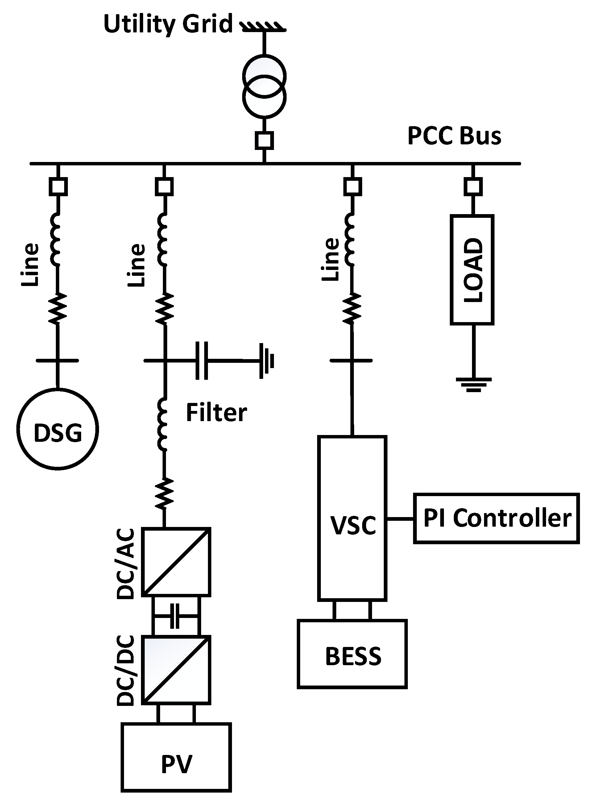
2. Problem Description

MG systems experience disturbances due to many reasons. These disturbances include a sudden loss of power generation, short circuits, and sudden load changes. Therefore, a proper control strategy is greatly needed to improve the power quality and restore the system to its initial steady state condition in case of contingencies. The main theme of this paper is to study the behavior of the MG system under transients. Accordingly, an innovative BESS-based controller was designed to improve the MG power quality during abnormal operating conditions by restoring the system frequency and voltage to normal operating conditions. The MG system being studied in this paper worked on the grid-connected mode and consisted of two distributed generations, which were a DSG and PV power system. Figure 1 shows the single line diagram of the MG system under consideration.
In order to improve the system power quality during transients, an intelligent BESS-based PI controller is proposed. The BESS was interfaced through voltage source converter (VSC) to provide an additional active and reactive power support for the MG system. The controller parameters were optimized under several levels of disturbances using the DEO technique. These disturbances simulated sudden changes in the input mechanical torque of the DSG. The optimized controller parameters and the corresponding disturbances were arranged in input and output patterns for training the ANN. Finally, the proposed intelligent BESS-based PI controller was evaluated under random disturbances, and its performance is compared with a benchmark controller.

3. Mathematical System Modelling

The MG had two DG sources integrated together and connected to the PCC bus. In addition, the battery storage system interfaced through a VSC along with the static loads was connected to the PCC bus. The MG system can be modeled by several nonlinear differential equations that represent its dynamic behavior. Figure 2 shows the detailed layout of the MG system under investigation.
The following sections provide detailed mathematical representations of each component of the MG system.

3.1. Diesel Synchronous Generator

The DSG can be modeled by four nonlinear first order differential equations. Two equations represent the mechanical part of the generator and decomposed from the well-known swing equation. The angular displacement (δ) of the generator rotor and angular speed (ω) are mathematically described as [37]:
d δ d t = ω b ( ω 1 )
d ω d t = 1 2 H ( P m P e )
where:
  • P e : output electrical power
  • P m : input mechanical power
  • H : inertia constant
  • ω b : reference angular speed.
The other two equations represent the electrical part of the generator and they are as follows:
d e q d t = 1 T d 0 [ E f d e q ( x d x d ) i g d ]
d E f d d t = 1 T A [ K A ( V g 0 V g ) ( E f d E f d 0 ) ]
where:
  • x d : d-axis synchronous reactance
  • x d : d-axis transient reactance
  • T A : exciter time constant
  • K A : exciter gain
  • T d 0 : open circuit field constant
  • E f d 0 : reference field voltage
  • V 0 : DSG reference terminal voltage.
The expression in Equation (3) describes the internal voltage e q along the quadrature axis (q-axis) of the generator’s rotor. While, the expression in Equation (4) describes the field voltage E f d along the direct axis (d-axis) of the generator’s rotor. The state variables of the DSG model are given as:
X DSG = [ δ , ω , e q , E f d ] .

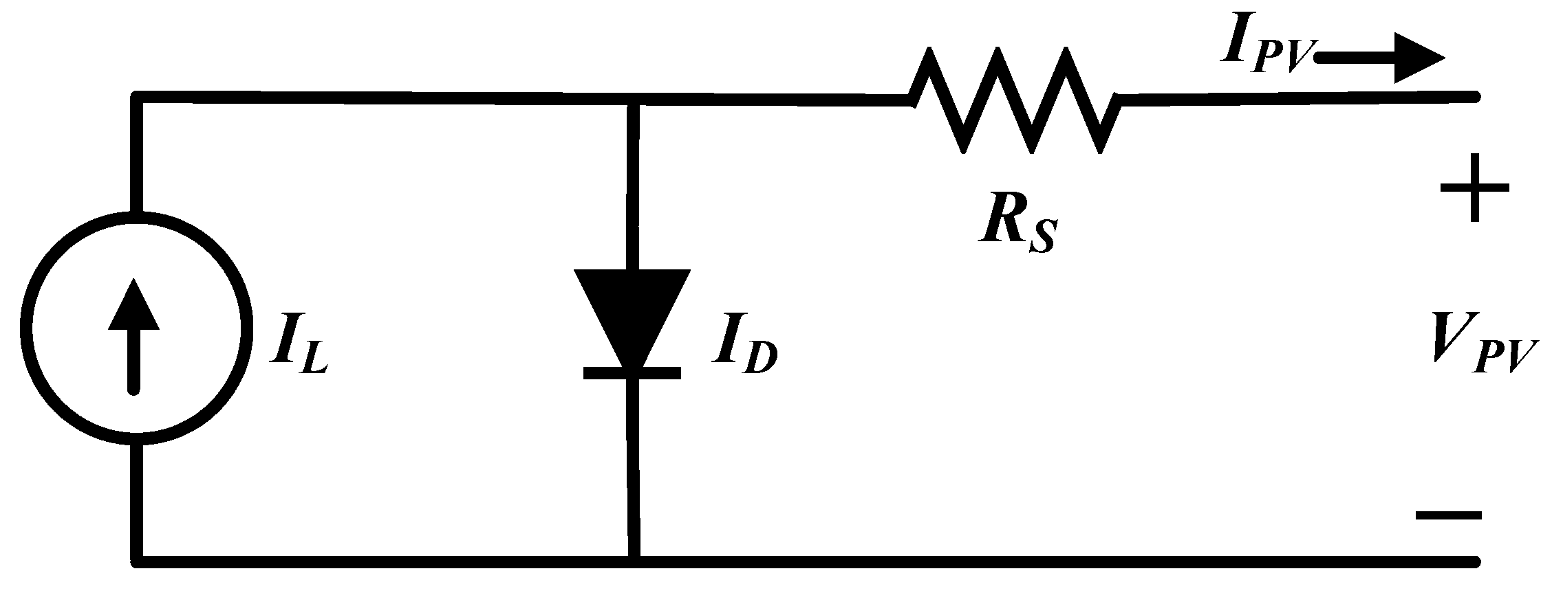
3.2. Photovoltaic System

The solar cell is the fundamental block of the PV system, and it consists mainly of a current source, diode, and resistance. The equivalent circuit shown in Figure 3 is called the simplified-PV model, which consists of a current source, a diode, and a series resistor.
The PV system can be modeled by eight nonlinear first order differential equations [37]. These equations represent the dynamic behavior of the PV cell, the associated power electronics, and the inductance–capacitance (LC) filter as well.

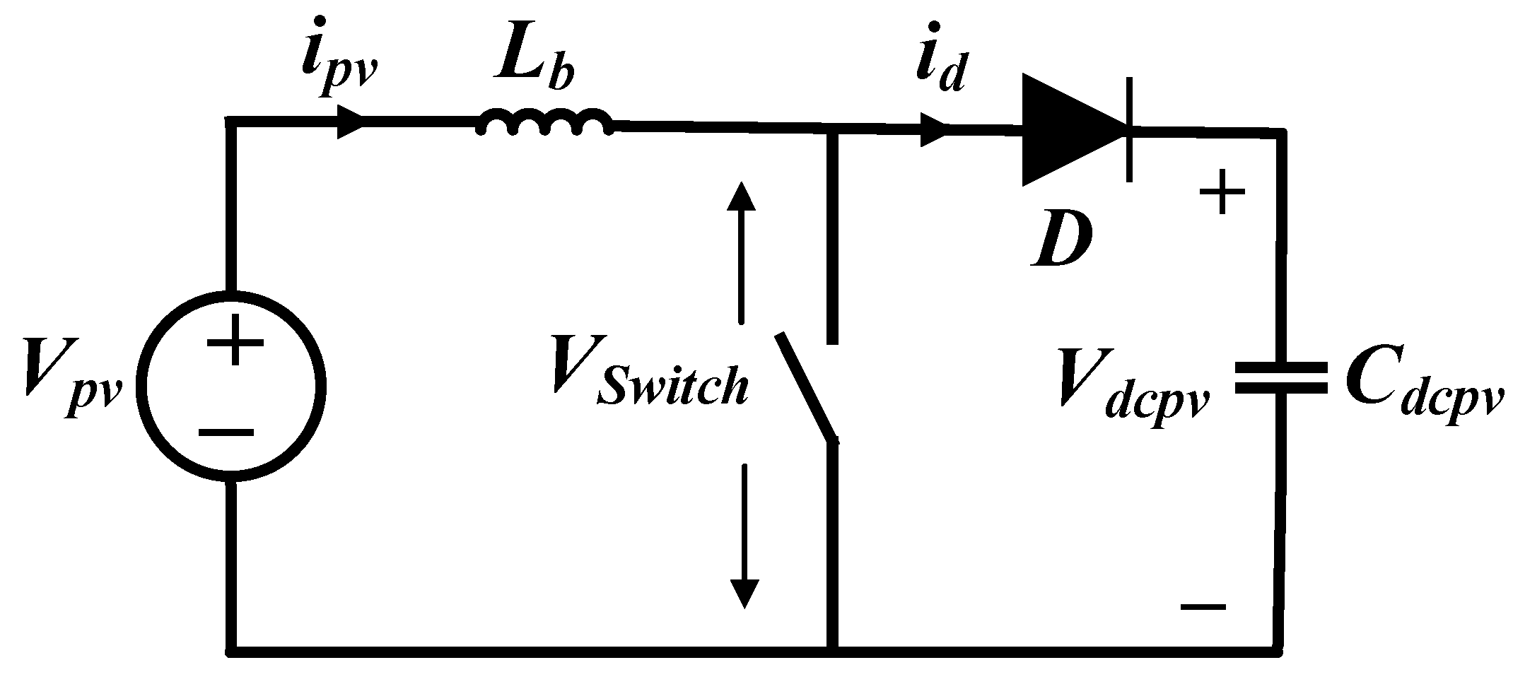
3.2.1. DC/DC Converter and DC Link

The equivalent circuit of the DC/DC boost converter is shown in Figure 4. It consists of an energy storing inductor, an insulated-gate bipolar transistor (IGBT) switch, a forward acting diode, and a DC link capacitor to filter the DC boost converter voltage and maintain constant input voltage to the DC/AC inverter.
The relations of Equations (5) and (6) represent the PV output current and the DC link output voltage after the DC/DC converter respectively.
d i p v d t = 1 L d c b [ V p v ( 1 d r p v ) V d c p v ]
d v d c p v d t = 1 C d c p v [ ( 1 d r p v ) i p v m p v i p f d cos ( ψ p v + θ ) ]
where:
  • L d c b : boost converter inductor
  • C d c p v : DC link capacitor
  • d r p v : DC/DC converter duty ratio.

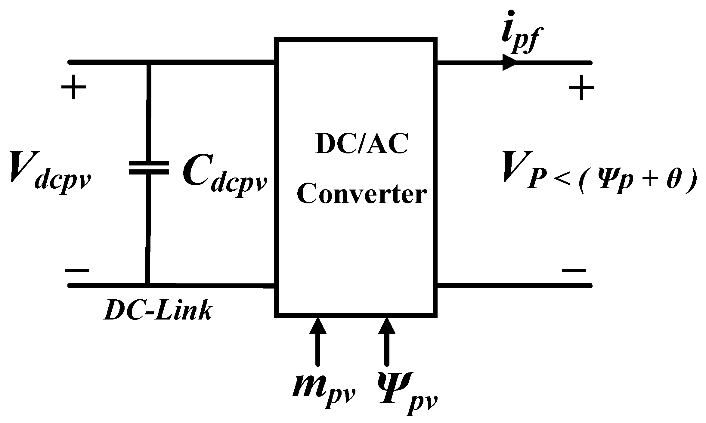
3.2.2. DC/AC Voltage Source Inverter

The voltage source DC/AC inverter (VSI) operated in pulse-width modulation (PWM) mode with a modulation index m p v and a phase angle ψ p v . The inverter is essential to convert the DC power to an AC in order to integrate the PV system with the PCC bus. Figure 5 shows the inverter model.
The mathematical expressions in Equations (7) and (8) represent the inverter output current in the d-axis, and the inverter output current in the q-axis, respectively.
d i p f d d t = w 0 R p f L p f i p f d + w o w i p f q + w o m p v V d c p v cos ( ψ p v + θ ) L p f w o V c p d L p f w o R p d r ( i p f d i p d )
d i p d q d t = w 0 R p f L p f i p f q + w o w i p f d + w o m p v V d c p v sin ( ψ p v + θ ) L p f w o V c p q L p f w o R p d r ( i p f q i p q )
where:
  • m P V : inverter modulation index
  • ψ P V : inverter phase angle.

3.2.3. LC Filter and Coupling Transmission Line

Figure 6 shows the LC low pass filter equivalent circuit along with the transmission line model.
The following set of mathematical expressions in Equations (9)–(12) represent the LC filter current in the d-axis, the LC filter current in the q-axis, the filter capacitor voltage in the d-axis, and the filter capacitor voltage in the q-axis respectively.
d i p d d t = w 0 R p L p i p d + w o w i p q + w o L p ( V c p d V s d ) + w o R p d r ( i p f d i p d )
d i p q d t = w 0 R p L p i p q + w o w i p d + w o L p ( V c p q V s q ) + w o R p d r ( i p f q i p q )
d V c p d d t = 1 C p f ( i p f d i p d ) + w o w V c p q
d V c p q d t = 1 C p f ( i p f q i p q ) + w o w V c p d
where:
  • R p f : filter resistance
  • R p : coupling line resistance
  • L p f : filter inductance
  • L p : coupling line inductance
  • C p f : filter capacitor
  • R p d r : damping resistor.
The state variables of the PV system model are given as:
X P V = [ i p v , V d c p v , i p f d , i p f q , i p d , i p q , V c p d , V c p q ] .

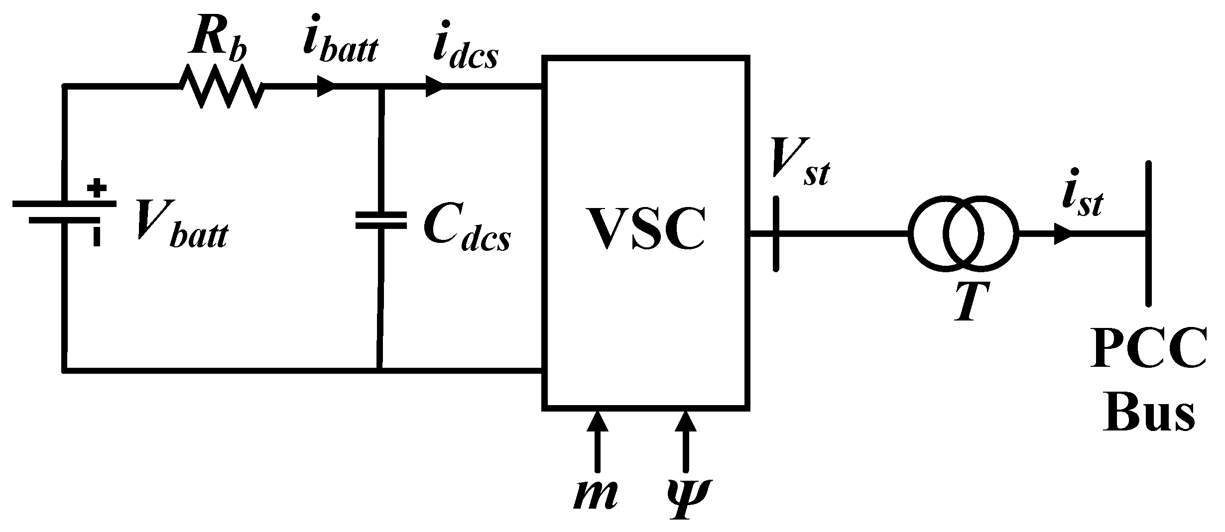
3.3. Battery Energy Storage System

The BESS can be modeled as a single DC source connected in series with a resistor and integrated with the PCC bus through a VSC, as shown in Figure 7. The BESS model that is given in Equations (13) and (14) describes the currents in the d-axis and q-axis, whereas the expression in Equation (15) represents the voltage of the DC-link capacitor [37].
d i s t d d t = w 0 R s t L s t i s t d + w w 0 i s t q + w 0 L s t ( m V d c s cos ( θ + ψ ) V s d )
d i s t q d t = w 0 R s t L s t i s t q + w w 0 i s t d + w 0 L s t ( m V d c s sin ( θ + ψ ) V s q )
d V d c s d t = m C d c s ( i s t q cos ( ψ ) + i s t q sin ( ψ ) ) + V b a t t V d c s R b C d c s
where:
  • R s t : VSC resistance
  • L s t : VSC inductance
  • m : converter modulation index
  • ψ : converter phase angle
  • C d c s : DC-link capacitance
  • R b : battery resistance.
The state variables of the BESS system model are given as:
X BESS = [ i s t d , i s t q , V d c s ] .

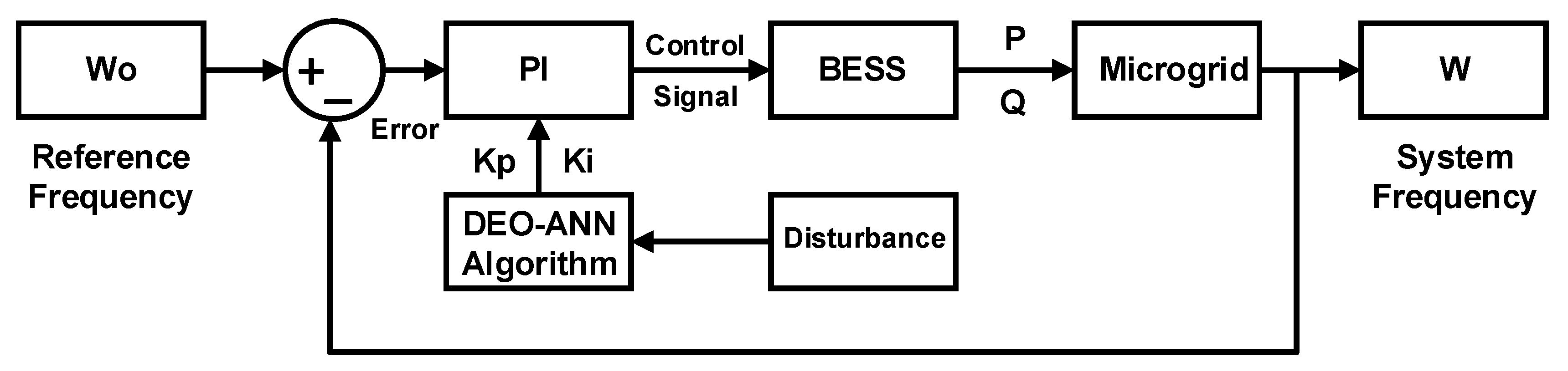
4. Problem Formulation

The aim is to improve the MG power quality by restoring the system frequency and voltage to the steady state condition in the case of having a disturbance in the input mechanical power of the DSG. To solve this optimization problem, the optimal design of the PI controller that gives the minimum frequency error was carried out. Therefore, the objective function was to minimize the system frequency integral squared-error (ISE) as follows:
M i n 0 t ( Δ ω ) 2 d t = 0 t ( ω 0 ω ) 2 d t
where:
  • ω 0 : reference frequency
  • ω : system frequency.
In doing so, some constraints on the PI controller limits were met. The proportional parameter ( K P ) and the integral parameter ( K i ) were as follows:
70 K P 250
70 K i 250
The acceptable operating limits of the MG frequency and voltage are given in Table 1.

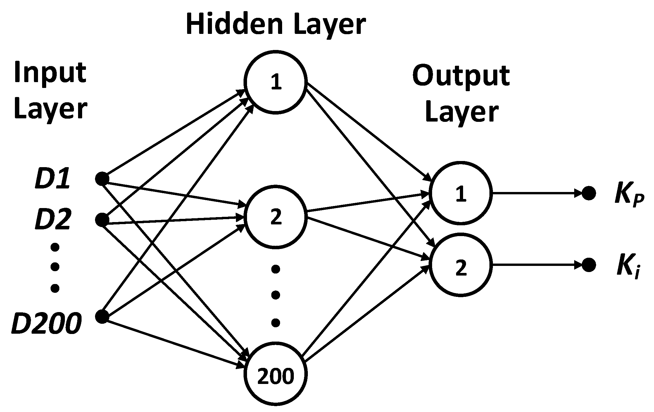
5. The Proposed Methodology

The proposed control methodology in this work was to use hybrid DEO and ANN techniques to optimize the BESS-based PI controller. The main role of the energy storage-based PI controller was to improve the power quality and restore the system to its steady state condition after the occurrence of a disturbance. In order to achieve this type of control, a proper selection of the controller parameters was required. Figure 8 shows the control block diagram of the MG system, where the system frequency was compared to a reference frequency. The mismatch between the two frequencies represented the error that needed to be minimized. Then, this error signal was entered into the PI controller, and the output control signal was as per Equation (17). The DEO-ANN algorithm generated the optimal controller parameters ( K P and K i ) depending on the disturbance level.
C o n t r o l _ S i g n a l = K P e ( t ) + K i 0 t e ( t ) d t .
The control signal controlled the VSC of the BESS through the modulation index (m) and the phase angle (ψ). Accordingly, the BESS supplied or absorbed both active (P) and reactive power (Q) depending on the system needs. The real power enhanced the dynamic performance through quick damping of the oscillations. Consequently, the MG frequency returned to the steady state condition, while the reactive power improved the voltage recovery at the PCC bus. As a result, the MG power quality was improved.
The DEO algorithm was used as an optimization technique to find the optimal values of the controller gains. The DEO is one type of the evolutionary algorithms (EAs) which are population-based optimization techniques. Other EAs include genetic algorithms (GA), genetic programming (GP), evolutionary programming (EP), and evolution strategy (ES) [43]. The DEO is distinguished by its simplicity, robustness and fast convergence. Also, DEO is suitable to solve systems that can be represented by non-linear differential equations [44]. Since the MG system under consideration consisted of several non-linear differential equations, the DEO technique was proposed in this paper to optimize the parameters of the PI controller. The parameter settings of the DEO algorithm are shown in Table 2. The optimal generation number and population size were determined by experience and by trial and error during the simulation until the best performance was achieved, whereas typical values were chosen for the crossover and mutation factors.
The flow chart of the proposed methodology is shown in Figure 9. As can be seen, the algorithm started with the initialization of DEO, and then different levels of disturbances were applied to the input mechanical torque of DSG. These disturbances simulated sudden changes in the mechanical part of the DSG. Both, the optimum solutions ( K P and K i ) and the disturbance level for each operating condition were obtained and stored. Then, these stored parameters were used to train the ANN. Once the ANN was trained, then the weighting matrices could identify the controller parameters for a certain operating condition within the training range.
Figure 10 shows the developed ANN model. As can be seen, it consisted of an input layer with 200 levels of disturbances ranging from 0.2 p.u to 0.8 p.u, a hidden layer with 200 neurons, and an output layer with two neurons that gave the optimized controller parameters ( K P and K i ). The backpropagation algorithm was used as a training algorithm with a hyperbolic tangent activation function for the hidden neurons and a linear activation function for the output neurons.
Figure 11 shows the performance curve of the developed ANN that was trained to give the optimal PI controller parameters for any disturbance within the training range. It can be observed clearly that the best training performance was found to be at epoch number 4 at which the mean squared error (MSE) converged to zero, which indicated that the developed ANN was very well trained.

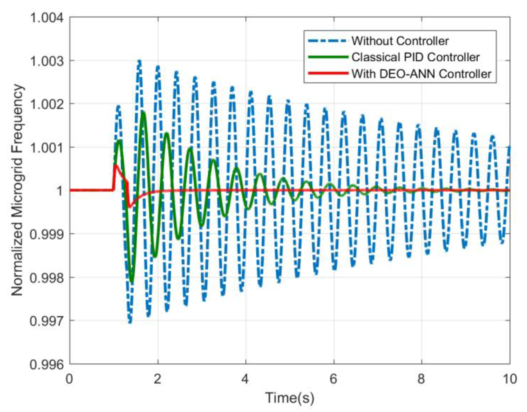
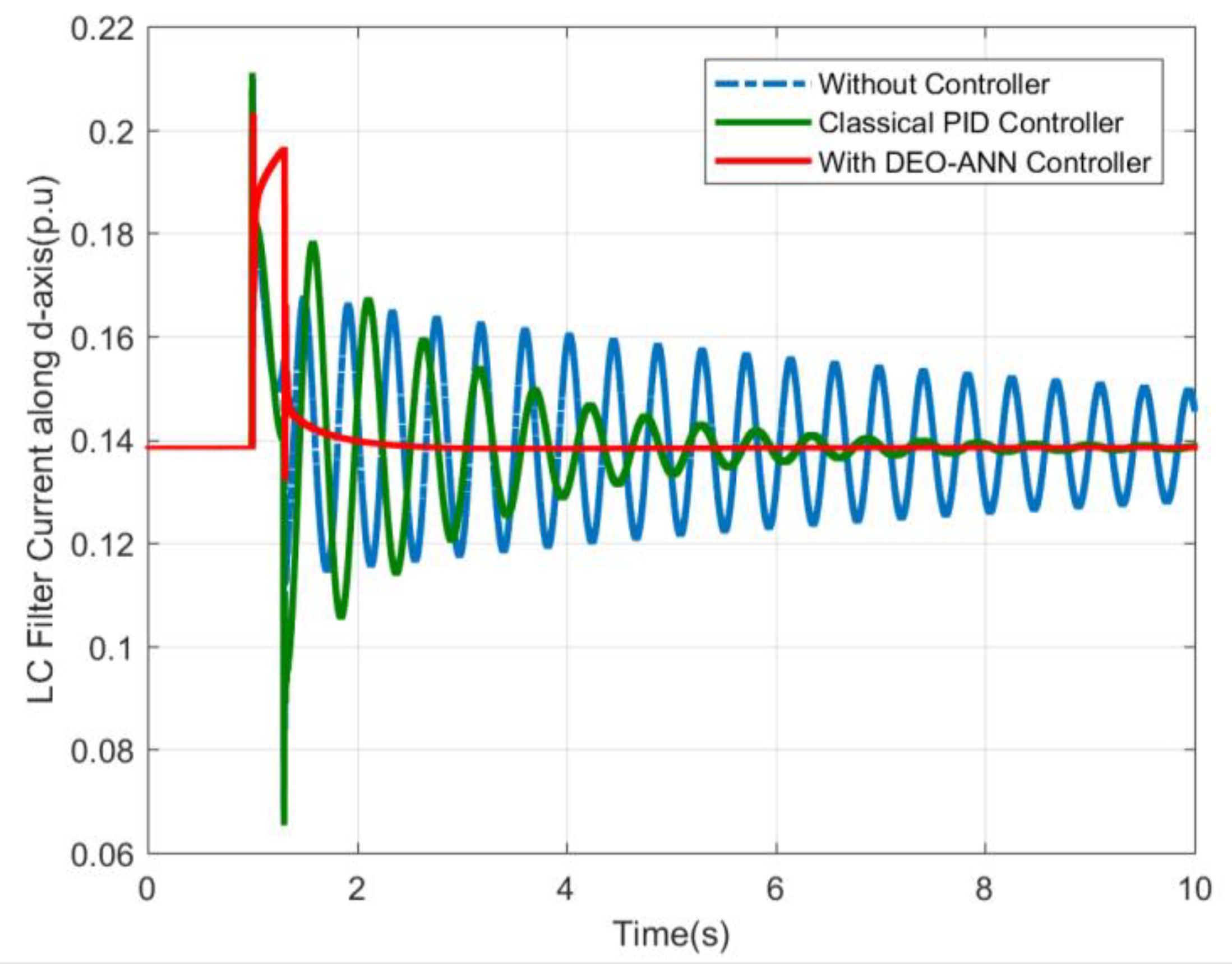
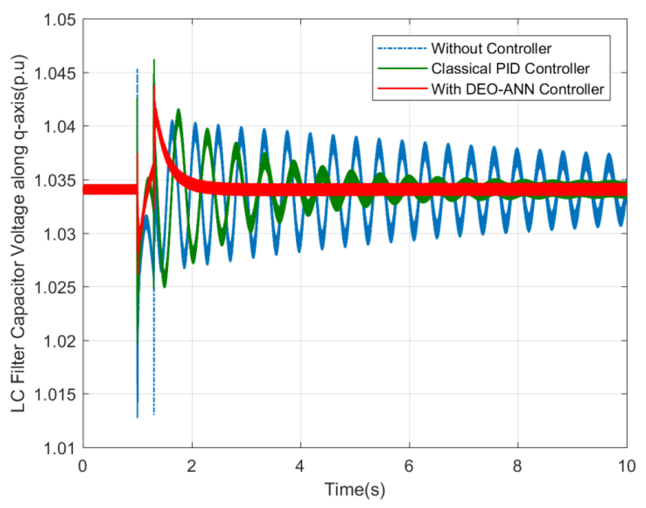
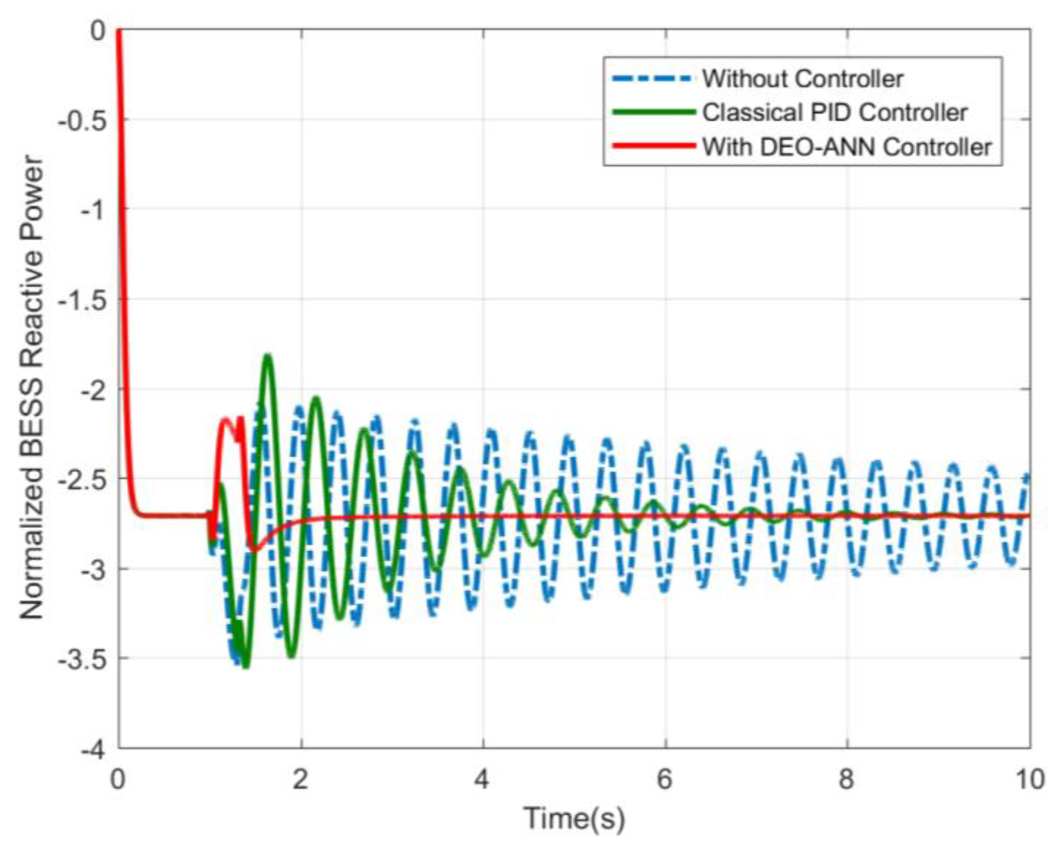
6. Results and Discussions

After completing the training of the ANN, a random disturbance between [0.2~0.8 p.u] was generated (0.3135 p.u) in order to verify the performance of the trained ANN. The input disturbance entered into the ANN, and then the output controller parameters were obtained as shown in Table 3 without violating the specified controller parameters’ constraints.
The dynamic responses of the system with and without the action of the controller along with the comprehensive comparison for the proposed DEO-ANN controller and the well-known benchmark classical PID controller is shown in Figure 12, Figure 13, Figure 14, Figure 15, Figure 16, Figure 17, Figure 18, Figure 19, Figure 20, Figure 21, Figure 22, Figure 23, Figure 24 and Figure 25. In fact, the classical PID controller is widely used as a benchmark controller, and many papers in the literature compare the performance of their proposed controllers with the performance of the classical PID controller [34,35,36,37]. The PID block in MATLAB SIMULINK was utilized which had the control formula shown in Equation (18). The PID controller parameters were tuned using the well-known Ziegler–Nichols method [45].
P I D _ C o n t r o l _ S i g n a l = K P e ( t ) + K i 0 t e ( t ) d t + K D d d t e ( t )
Figure 12 and Figure 13 demonstrate the performance comparison of the proposed DEO-ANN controller using the obtained controller parameters from the developed ANN. It can be observed that the proposed controller performed better than the benchmark model in terms of stabilization time to restore the MG system frequency and voltage to the normal operating condition within a period of 1.5 s.
The variations in the DSG internal voltage and the field voltage are shown in Figure 14 and Figure 15, respectively. It can be seen from those two figures that in the absence of the control action, the oscillations in the DSG internal voltage and field voltage continued for a longer period of time. However, with the action of the intelligent BESS controller, the oscillations were damped quickly and returned to the steady-state condition in 3 s for the DSG internal voltage and less than 1.5 s for the DSG field voltage.
The transient responses of the PV output current and the DC link output voltage are recorded in Figure 16 and Figure 17. Without the proposed controller, the PV output current and the DC link output voltage fluctuated for more than 10 s. However, with the action of the intelligent BESS controller, the fluctuations were damped quickly, restoring the PV output current and the DC link output voltage to the steady-state condition in less than 2 s.
Figure 18 and Figure 19 show the responses of the inverter output current along the d-axis and the inverter output current along the q-axis, respectively. It can be noticed from these figures that the uncontrolled case led to continuous oscillations. However, the transient responses with the proposed controller were improved, and the inverter output current along the d-axis and along the q-axis restored to the steady-state condition in less than 1.5 s.
Figure 20, Figure 21, Figure 22 and Figure 23 show the transient responses of the LC filer output current along the d-axis, the LC filer output current along the q-axis, the LC filter capacitor voltage along the d-axis, and the LC filter capacitor voltage along the tq-axis respectively. It can be observed from these four figures that in the absence of the controller action, the oscillations in the LC filter output current along the d-axis, the LC filter output current along the q-axis, the LC filter capacitor voltage along the d-axis, and the LC filter capacitor voltage along the q-axis continued for a longer period of time. However, the responses in the presence of controller action were enhanced, and the system returned to the steady-state conditions in less than 1.5 s. Moreover, the performance of the proposed DEO-ANN controller surpassed the performance of the classical PID controller in all of the four figures.
Figure 24 and Figure 25 show the BESS performance during transients with and without the action of the proposed PI controller. The BESS behaved randomly without a proper controller and fluctuated for a long period of time. On the other hand, with the use of the intelligent PI controller, the BESS restored the system to steady-state conditions within 1 s. As can be seen in Figure 24, the sudden changes in the input mechanical torque of the DSG were mitigated by the BESS injection or absorption of real power. This will reduce the amplitude of the oscillations in various MG system quantities, particularly the system frequency. Similarly, the variations of the PCC MG voltage during contingencies were reduced by the VSC-interfaced BESS injection or absorption of reactive power, as shown in Figure 25. The proposed PI controller successfully managed the active and reactive power flow from and to the BESS in order to maintain the system frequency and voltage within the prescribed operating limits.
It can be observed from the simulation results that the proposed DEO-ANN controller performed better in terms of stabilization time and overshoot when compared with the benchmark PID controller in all given scenarios. Although there was a tradeoff between the stabilization time and overshoot, the proposed controller was capable of keeping both the percentage of overshoot along with stabilization time to a minimum level.

7. Conclusions

A novel online intelligent BESS-based controller has been proposed in this paper to improve the power quality of a MG system; in particular, voltage control and frequency regulation at steady state conditions were targeted. The overall strategy was based on the combination of two key techniques, DEO and ANN, thus making a hybrid control system that actually benefits from complementary benefits of both approaches. To the best of authors’ knowledge, the proposed approach in this paper has not been proposed earlier in the literature. The frequency and voltage at the PCC bus of the MG have been maintained within prescribed operating limits during normal and transients’ conditions. The controller parameters have been optimized using the DEO technique under different low-level disturbances. Consequently, the optimized controller parameters and the corresponding disturbances were arranged in input and output patterns for the purpose of training the ANN. Finally, the proposed intelligent BESS-based PI controller has been evaluated under random disturbances in order to verify its performance as compared with a benchmark controller. The simulation results proved the effectiveness of the proposed DEO-ANN control strategy. Hence the developed intelligent controller is ready for optimal online tuning of controller parameters under the influence of unknown low-level disturbances. Future work will be on extending the proposed control approach to handle critical disturbances in autonomous microgrids.

Author Contributions

Conceptualization, J.A. and M.K.; methodology, J.A.; software, J.A.; validation, J.A., M.K., and A.A.; formal analysis, J.A., M.K. and A.A.; investigation, J.A., M.K. and A.A.; resources, M.K.; data curation, J.A.; writing—original draft preparation, J.A., M.K. and A.A.; writing—review and editing, J.A. and M.K.; visualization, J.A., M.K. and A.A.; supervision, M.K. and A.A.; project administration, J.A. and M.K.; funding acquisition, M.K.

Funding

The authors would like to acknowledge the support provided by the Deanship of Research (DSR) at King Fahd University of Petroleum and Minerals (KFUPM) for funding this work through project No. RG171009. In addition, Muhammad Khalid would like to acknowledge the funding support provided by the King Abdullah City for Atomic and Renewable Energy (K.A. CARE).

Acknowledgments

We would like to thank Mohammed Ali for his assistance in finalizing the model parameters.

Conflicts of Interest

The authors declare no conflict of interest.

Nomenclature

ANNArtificial neural networks
BESSBattery energy storage system
DEODifferential evolution optimization
DERDistrusted energy resources
DGDistrusted generation
DSGDiesel synchronous generator
EAEvolutionary algorithms
EPEvolutionary programming
ESEvolution strategy
ESDEnergy storage devices
ESSEnergy storage system
FCFuel cells
FESSFlywheel energy storage system
FLFuzzy logic
FRFrequency restoration
GAGenetic algorithm
GPGenetic programming
GTGas turbines
HILHardware-in-loop
HTHydro turbines
ICEInternal combustion engines
IGBTInsulated-gate bipolar transistor
ISEIntegral squared-error
LCInductance-capacitance
MGMicrogrid
PCCPoint of common coupling
PIProportional-integral
PIDProportional-integral-derivative
PSOParticle swarm optimization
PVPhotovoltaic system
PWMPulse-width modulation
RESRenewable energy sources
RPSReactive power-sharing
SCESSSuper-capacitor energy storage system
SMESSuperconducting magnetic energy storage
VSCVoltage source converter
VSIVoltage source inverter

References

  1. Ustun, T.S.; Ozansoy, C.; Zayegh, A. Recent developments in microgrids and example cases around the world—A review. Renew. Sustain. Energy Rev. 2011, 15, 4030–4041. [Google Scholar] [CrossRef]
  2. Kaviri, S.M.; Pahlevani, M.; Jain, P.; Bakhshai, A. A review of ac microgrid control methods. In Proceedings of the 8th International Symposium on Power Electronics for Distributed Generation Systems (PEDG), Florianópolis, Brazil, 17–20 April 2017; pp. 1–8. [Google Scholar]
  3. Khalid, M.; Akram, U.; Shafiq, S. Optimal planning of multiple distributed generating units and storage in active distribution networks. IEEE Access 2018, 6, 55234–55244. [Google Scholar] [CrossRef]
  4. Jiayi, H.; Chuanwen, J.; Rong, X. A review on distributed energy resources and microgrid. Renew. Sustain. Energy Rev. 2008, 12, 2472–2483. [Google Scholar] [CrossRef]
  5. Mahmoud, M.S.; Hussain, S.A.; Abido, M.A. Modeling and control of microgrid: An overview. J. Frankl. Inst. 2014, 351, 2822–2859. [Google Scholar] [CrossRef]
  6. Basak, P.; Chowdhury, S.; nee Dey, S.H.; Chowdhury, S. A literature review on integration of distributed energy resources in the perspective of control, protection and stability of microgrid. Renew. Sustain. Energy Rev. 2012, 16, 5545–5556. [Google Scholar] [CrossRef]
  7. Lidula, N.; Rajapakse, A. Microgrids research: A review of experimental microgrids and test systems. Renew. Sustain. Energy Rev. 2011, 15, 186–202. [Google Scholar] [CrossRef]
  8. Li, Y.; Yang, Z.; Li, G.; Mu, Y.; Zhao, D.; Chen, C.; Shen, B. Optimal scheduling of isolated microgrid with an electric vehicle battery swapping station in multi-stakeholder scenarios: A bi-level programming approach via real-time pricing. Appl. Energy 2018, 232, 54–68. [Google Scholar] [CrossRef] [Green Version]
  9. Vechiu, I.; Curea, O.; Llaria, A.; Camblong, H. Control of power converters for microgrids. COMPEL 2011, 30, 300–309. [Google Scholar] [CrossRef]
  10. Marwali, M.N.; Jung, J.-W.; Keyhani, A. Control of distributed generation systems-part ii: Load sharing control. IEEE Trans. Power Electron. 2004, 19, 1551–1561. [Google Scholar] [CrossRef]
  11. Carrasco, J.M.; Franquelo, L.G.; Bialasiewicz, J.T.; Galván, E.; PortilloGuisado, R.C.; Prats, M.M.; León, J.I.; Moreno-Alfonso, N. Power-electronic systems for the grid integration of renewable energy sources: A survey. IEEE Trans. Ind. Electron. 2006, 53, 1002–1016. [Google Scholar] [CrossRef]
  12. Blaabjerg, F.; Chen, Z.; Kjaer, S.B. Power electronics as efficient interface in dispersed power generation systems. IEEE Trans. Power Electron. 2004, 19, 1184–1194. [Google Scholar] [CrossRef]
  13. Katiraei, F.; Iravani, M.R.; Lehn, P.W. Micro-grid autonomous operation during and subsequent to islanding process. IEEE Trans. Power Deliv. 2005, 20, 248–257. [Google Scholar] [CrossRef]
  14. Tsikalakis, A.G.; Hatziargyriou, N.D. Centralized control for optimizing microgrids operation. In Proceedings of the Power and Energy Society General Meeting, San Diego, CA, USA, 24–29 July 2011; pp. 1–8. [Google Scholar]
  15. Zamora, R.; Srivastava, A. Controls for microgrids with storage: Review, challenges, and research needs. Renew. Sustain. Energy Rev. 2010, 14, 2009–2018. [Google Scholar] [CrossRef]
  16. Ribeiro, P.F.; Johnson, B.K.; Crow, M.L.; Arsoy, A.; Liu, Y. Energy storage systems for advanced power applications. Proc. IEEE 2001, 89, 1744–1756. [Google Scholar] [CrossRef]
  17. Akram, U.; Khalid, M. A coordinated frequency regulation framework based on hybrid battery-ultracapacitor energy storage technologies. IEEE Access 2018, 6, 7310–7320. [Google Scholar] [CrossRef]
  18. Valverde, L.; Rosa, F.; Bordons, C. Design, planning and management of a hydrogen-based microgrid. IEEE Trans. Ind. Inform. 2013, 9, 1398–1404. [Google Scholar] [CrossRef]
  19. Díaz-González, F.; Sumper, A.; Gomis-Bellmunt, O.; Villafáfila-Robles, R. A review of energy storage technologies for wind power applications. Renew. Sustain. Energy Rev. 2012, 16, 2154–2171. [Google Scholar] [CrossRef]
  20. Li, Y.; Yang, Z.; Zhao, D.; Lei, H.; Cui, B.; Li, S. Incorporating energy storage and user experience in isolated microgrid dispatch using a multi-objective model. IET Renew. Power Gener. 2019, 13, 973–981. [Google Scholar] [CrossRef]
  21. Zhao, B.; Chen, J.; Zhang, L.; Zhang, X.; Qin, R.; Lin, X. Three representative island microgrids in the east china sea: Key technologies and experiences. Renew. Sustain. Energy Rev. 2018, 96, 262–274. [Google Scholar] [CrossRef]
  22. López-González, A.; Domenech, B.; Ferrer-Martí, L. Sustainability and design assessment of rural hybrid microgrids in venezuela. Energy 2018, 159, 229–242. [Google Scholar] [CrossRef]
  23. Bellido, M.H.; Rosa, L.P.; Pereira, A.O.; Falcão, D.M.; Ribeiro, S.K. Barriers, challenges and opportunities for microgrid implementation: The case of federal university of rio de janeiro. J. Clean. Prod. 2018, 188, 203–216. [Google Scholar] [CrossRef]
  24. Feng, W.; Jin, M.; Liu, X.; Bao, Y.; Marnay, C.; Yao, C.; Yu, J. A review of microgrid development in the united states–a decade of progress on policies, demonstrations, controls, and software tools. Appl. Energy 2018, 228, 1656–1668. [Google Scholar] [CrossRef]
  25. Green, T.; Prodanović, M. Control of inverter-based micro-grids. Electr. Power Syst. Res. 2007, 77, 1204–1213. [Google Scholar] [CrossRef] [Green Version]
  26. Kumar, M.; Tyagi, B. A state of art review of microgrid control and integration aspects. In Proceedings of the 7th India International Conference on Power Electronics (IICPE), Patiala, India, 17–19 November 2016; pp. 1–6. [Google Scholar]
  27. Parhizi, S.; Lotfi, H.; Khodaei, A.; Bahramirad, S. State of the art in research on microgrids: A review. IEEE Access 2015, 3, 890–925. [Google Scholar] [CrossRef]
  28. Bevrani, H.; Habibi, F.; Babahajyani, P.; Watanabe, M.; Mitani, Y. Intelligent frequency control in an ac microgrid: Online pso-based fuzzy tuning approach. IEEE Trans. Smart Grid 2012, 3, 1935–1944. [Google Scholar] [CrossRef]
  29. Rajesh, K.; Dash, S.; Rajagopal, R.; Sridhar, R. A review on control of ac microgrid. Renew. Sustain. Energy Rev. 2017, 71, 814–819. [Google Scholar] [CrossRef]
  30. Zhang, Z.; Dou, C.; Yue, D.; Zhang, B.; Luo, W. A decentralized control method for frequency restoration and accurate reactive power sharing in islanded microgrids. J. Frankl. Inst. 2018, 355, 8874–8890. [Google Scholar] [CrossRef]
  31. Yang, P.; Xia, Y.; Yu, M.; Wei, W.; Peng, Y. A decentralized coordination control method for parallel bidirectional power converters in a hybrid ac–dc microgrid. IEEE Trans. Ind. Electron. 2018, 65, 6217–6228. [Google Scholar] [CrossRef]
  32. Faisal, M.; Hannan, M.; Ker, P.J.; Hussain, A.; Mansur, M.; Blaabjerg, F. Review of energy storage system technologies in microgrid applications: Issues and challenges. IEEE Access 2018, 6, 35143–35164. [Google Scholar] [CrossRef]
  33. Akram, U.; Khalid, M.; Shafiq, S. An innovative hybrid wind-solar and battery-supercapacitor microgrid system—Development and optimization. IEEE Access 2017, 5, 25897–25912. [Google Scholar] [CrossRef]
  34. Parise, G.; Martirano, L.; Kermani, M.; Kermani, M. Designing a power control strategy in a microgrid using pid/fuzzy controller based on battery energy storage. In Proceedings of the International Conference on Environment and Electrical Engineering and Industrial and Commercial Power Systems Europe (EEEIC/I&CPS Europe), Milan, Italy, 6–9 June 2017; pp. 1–5. [Google Scholar]
  35. Kermani, M. Transient voltage and frequency stability of an isolated microgrid based on energy storage systems. In Proceedings of the 16th International Conference on Environment and Electrical Engineering (EEEIC), Florence, Italy, 7–10 June 2016; pp. 1–5. [Google Scholar]
  36. Li, H.; Wang, X.; Xiao, J. Differential evolution-based load frequency robust control for micro-grids with energy storage systems. Energies 2018, 11, 1686. [Google Scholar] [CrossRef]
  37. Ali, M.A. Control of a Microgrid through Energy Storage Devices using Evolutionary and Neuro-Fuzzy Methods. Master’s Thesis, King Fahd University of Petroleum and Minerals Dhahran, Dhahran, Saudi Arabia, 2013. [Google Scholar]
  38. Fu, C.; Tan, W. Decentralised load frequency control for power systems with communication delays via active disturbance rejection. IET Gener. Transm. Distrib. 2017, 12, 1397–1403. [Google Scholar] [CrossRef]
  39. Ma, M.; Zhang, C.; Liu, X.; Chen, H. Distributed model predictive load frequency control of the multi-area power system after deregulation. IEEE Trans. Ind. Electron. 2017, 64, 5129–5139. [Google Scholar] [CrossRef]
  40. Shankar, R.; Chatterjee, K.; Bhushan, R. Impact of energy storage system on load frequency control for diverse sources of interconnected power system in deregulated power environment. Int. J. Electr. Power Energy Syst. 2016, 79, 11–26. [Google Scholar] [CrossRef]
  41. Mu, C.; Tang, Y.; He, H. Improved sliding mode design for load frequency control of power system integrated an adaptive learning strategy. IEEE Trans. Ind. Electron. 2017, 64, 6742–6751. [Google Scholar] [CrossRef]
  42. Rinaldi, G.; Cucuzzella, M.; Ferrara, A. Third order sliding mode observer-based approach for distributed optimal load frequency control. IEEE Control Syst. Lett. 2017, 1, 215–220. [Google Scholar] [CrossRef]
  43. Dasgupta, D.; Michalewicz, Z. Evolutionary Algorithms in Engineering Applications; Springer Science & Business Media: Berlin, Germany, 2013. [Google Scholar]
  44. Storn, R. On the usage of differential evolution for function optimization. In Proceedings of the Biennial Conference of the North American Fuzzy Information Processing Society (NAFIPS), Berkeley, CA, USA, 19–22 June 1996. [Google Scholar]
  45. Åström, K.J.; Hägglund, T. Revisiting the ziegler–nichols step response method for pid control. J. Process Control 2004, 14, 635–650. [Google Scholar] [CrossRef]
Figure 1. Single line diagram of the microgrid (MG) system.
Energies 12 02112 g001
Figure 2. Detailed layout of the MG system.
Energies 12 02112 g002
Figure 3. Simplified-photovoltaic (PV) model.
Energies 12 02112 g003
Figure 4. The DC/DC converter circuit.
Energies 12 02112 g004
Figure 5. The voltage source inverter (VSI) model.
Energies 12 02112 g005
Figure 6. The inductance–capacitance (LC) filter and transmission line model.
Energies 12 02112 g006
Figure 7. The battery energy storage system (BESS) model.
Energies 12 02112 g007
Figure 8. MG control diagram model.
Energies 12 02112 g008
Figure 9. Flowchart of the proposed approach.
Energies 12 02112 g009
Figure 10. The artificial neural networks (ANN) model.
Energies 12 02112 g010
Figure 11. The ANN training performance curve.
Energies 12 02112 g011
Figure 12. MG system frequency (in p.u).
Energies 12 02112 g012
Figure 13. MG system voltage (in p.u).
Energies 12 02112 g013
Figure 14. Diesel synchronous generator (DSG) internal voltage.
Energies 12 02112 g014
Figure 15. DSG field voltage.
Energies 12 02112 g015
Figure 16. PV output current.
Energies 12 02112 g016
Figure 17. DC link output voltage.
Energies 12 02112 g017
Figure 18. Inverter output current along the d-axis.
Energies 12 02112 g018
Figure 19. Inverter output current along the q-axis.
Energies 12 02112 g019
Figure 20. LC filter output current along the d-axis.
Energies 12 02112 g020
Figure 21. LC filter output current along the q-axis.
Energies 12 02112 g021
Figure 22. LC filter capacitor voltage along the d-axis.
Energies 12 02112 g022
Figure 23. LC filter capacitor voltage along the q-axis.
Energies 12 02112 g023
Figure 24. Injected real power by the BESS.
Energies 12 02112 g024
Figure 25. Injected reactive power by the BESS.
Energies 12 02112 g025
Table 1. MG acceptable operating limits.
QuantityMinimum Value (p.u)Maximum Value (p.u)
Frequency0.9991.001
Voltage0.951.05
Table 2. The differential evolution optimization (DEO) algorithm parameter settings.
Parameter DescriptionValue
Generation number50
Population size20
Crossover factor0.5
Mutation factor0.5
Table 3. Proportional-integral (PI) controller parameters using the proposed approach.
Controller ParameterValue
Kp128.22
Ki161.78

