Investigation of Soot Formation in a Novel Diesel Fuel Burner
by

Natascia Palazzo
1,2,*, 
Matthias Kögl
1,2,
Philipp Bauer
1,
Manu Naduvil Mannazhi
3,
Lars Zigan
1,2,
Franz Johann Thomas Huber
1,2 and
Stefan Will
1,2 1
Lehrstuhl für Technische Thermodynamik (LTT), Friedrich-Alexander-Universität Erlangen-Nürnberg (FAU), 91058 Erlangen, Germany
2
Erlangen Graduate School in Advanced Optical Technologies (SAOT), Friedrich-Alexander-Universität Erlangen-Nürnberg (FAU), 91052 Erlangen, Germany
3
Combustion Physics, Faculty of Engineering, Lund University, P.O. Box 118, SE-221 00 Lund, Sweden
*
Author to whom correspondence should be addressed.
Energies 2019, 12(10), 1993; https://doi.org/10.3390/en12101993
Submission received: 16 April 2019
/
Revised: 14 May 2019
/
Accepted: 15 May 2019
/
Published: 24 May 2019
(This article belongs to the Section I: Energy Fundamentals and Conversion)
Abstract
:In the present work, a novel burner capable of complete pre-vaporization and stationary combustion of diesel fuel in a laminar diffusion flame has been developed to investigate the effect of the chemical composition of diesel fuel on soot formation. For the characterization of soot formation during diesel combustion we performed a comprehensive morphological characterization of the soot and determined its concentration by coupling elastic light scattering (ELS) and laser-induced incandescence (LII) measurements. With ELS, radii of gyration of aggregates were measured within a point-wise measurement volume, LII was employed in an imaging approach for a 2D-analysis of the soot volume fraction. We carried out LII and ELS measurements at different positions in the flame for two different fuel types, revealing the effects of small modifications of the fuel composition on soot emission during diesel combustion.
1. Introduction
The extensive use of fossil fuels as major energy carriers and the correlated emissions have caused serious environmental concerns among fuel producers, engine manufacturers, and public administration institutions. Emissions from engines include different chemical compounds like carbon monoxide (CO), nitric oxides (NOx), volatile organic compounds (VOCs), and particulate matter (PM). In particular, the majority of PM emitted by engines is composed of carbonaceous particles known as soot. These particles, as many scientific studies have demonstrated, can provoke harmful effects on human health and the environment [1]. In response to the forecasted emission regulations, much effort has been put into developing new engine generations as well as optimizing existing fuels [2]. In particular, improving fuel characteristics is a promising solution to reduce emissions. Two strategies have been proposed to achieve that: (1) Complete replacement of the petroleum-derived fuels with synthetic ones, and (2) inserting fuel additives capable of altering the fuel’s physical and chemical properties [3]. To further develop and optimize such strategies a deep comprehension of the soot formation mechanisms in the engine is necessary. There are many factors influencing soot emission from engines. Besides the chemical composition of the fuel, which is in the focus of the present study, soot formation in a diesel engine is influenced by physical processes. These include the atomization and resulting shape of the spray, the method of air supply, the mixture proportion, turbulence level, pressure, injection time, and ignition delay [4,5]. Consequently, a complete understanding of the extremely complex nature of this process is only achievable by studying the single factors affecting soot formation inside the engine separately. For example, identifying the chemical effects is decisive in order to determine the impact of additive insertion. Although significant progress has been made in the last years, a complete comprehension of the effect of the fuel chemical composition on soot generation is still missing. Fundamental studies on the chemical effects of fuel composition on soot production are possible by pre-vaporizing the diesel fuel before combustion, in order to avoid spray-related effects. Moreover, the investigation of a laminar diffusion flame from completely pre-vaporized diesel offers several advantages. Laminar diffusion flames provide simplified conditions that include the key steps of soot formation, growth and oxidation. Additionally, laminar flames are easier to model and permit easy access to apply diagnostic methods for the determination of species concentration, temperature, and soot parameters [6,7,8].
The goal of the present work is the realization and characterization of a system that allows to single-out the effect of the diesel fuel chemical composition on soot formation. The effect of minor modifications of the fuel chemical composition on the soot produced is of particular interest in this work. To that end, the strategy of complete vaporization of the fuel was adopted and a novel laminar burner was developed and built. Mainly two optical diagnostic techniques, laser-induced incandescence (LII) and elastic light scattering (ELS) were employed for the characterization of the soot produced. While LII allows for the 2D evaluation of soot concentration, expressed as volume fraction fv [9], ELS permits the measurement of crucial morphological characteristics (i.e., radii of gyration of the aggregates) [10]. The set of fuels tested include two reference diesels with a modest variation in the chemical composition (i.e., with a different content of aromatic species). The first fuel, CEC RF-06-03, is a certified diesel used as a reference (it has a total content of aromatics species of 24.4 wt.%, 20.2 wt.% mono aromatics) while the second fuel, CEC RF-79-07, is a certified reference fuel typically used as a baseline for additive insertion (total content of aromatics: 21.6 wt.%, 16.9 wt.% mono aromatics). For simplicity, CEC RF-06-03 will be referred to as “reference” fuel and CEC RF-79-07 as “baseline” fuel in the following. The soot particulates generated at various heights above the burner were characterized and compared for these fuels.
2. Background and Methods
2.1. Soot Characterization for Liquid Fuels
The sooting tendency of liquid fuels under various conditions has been the topic of a number of studies. Fundamental investigations on fossil fuel surrogates as well as on biodiesel surrogates have been performed both in shock tubes [11,12], premixed [13,14], and diffusion flames [15,16,17]. The studies of soot formation in diesel flames are limited; recent investigations, including the work of Solero [18] and Lemaire et al. [2,19], employed an atomizer to produce a fuel spray for direct vaporization of the fuel in the flame itself. Du et al. [20] studied the effects of injection pressure, nozzle orifice diameter, and gas density on soot formed in a turbulent diffusion diesel flame. The authors utilized a continuous gas flow high-pressure/high-temperature spray chamber. Matti Maricq [21] used a system composed of a syringe pump for fuel supply (diesel surrogate, biodiesel) and an injection nozzle to create a spray flame. In 2009, Lemaire et al. [22] designed a McKenna-Hybrid burner where a high-speed spray of micro-sized fuel droplets was formed at the nebulizer tip and directly injected in the burner, allowing it to generate a turbulent diffusion flame. However, for the investigation of the chemical mechanisms of soot formation it is especially important to reduce the effects of the fuel´s physical properties, such as density, viscosity, and surface tension of droplets, that significantly influence atomization and evaporation time in a spray flame. Only very few examples of non-spray flame burners, designed for combustion of high-temperature boiling point fuels, are present in the literature. Gerstmann et al. [23] described the concept of a vaporizing diesel burner for camp stoves and military field kitchens. In this set-up the fuel is vaporized in a vertical tube, directed through a super-heater tube, and then burned on a cylindrical screen flame holder. The flame generated is not easily controllable/reproducible and; therefore, not suitable for the quantification of the soot volume fraction or morphological investigations, but is restricted to practical applications. In the work of Bryce et al. [24], a diesel flame (with ~13 mm length) was generated in a burner system consisting of a vaporizer vessel, kept at 300 °C, joint to a co-flow burner by a heated tube where the fuel is pulse injected. The height of the flame produced was controlled by a needle valve. This set-up allowed for a stable flame; however, on the other hand, the pulsed injection had to be continuously controlled in order to preserve steady flame conditions.
For the present study, a continuous fuel flow as well as a compact system, allowing for enhanced homogenous conditions of the flame, are desirable. Furthermore, the complete vaporization of the realistic multi-component diesel fuel considered in the present study requires temperatures of at least 370 °C. This is a challenge due to low self-ignition temperature (for commercial diesel at 210 °C), an issue discussed in Section 3.1.
2.2. Laser-Induced Incandescence
Laser-induced incandescence (LII) is based on the heating of (usually carbonaceous) particles with a short laser pulse up to the sublimation temperature and the analysis of the subsequent enhanced thermal radiation signal [25]. This technique has received increasing attention as it allows for a temporally- and spatially-resolved visualization of soot concentration [26]. Theoretical analysis has shown that, for sufficient intensities of the laser pulse, the maximum LII signal is approximately proportional to the local soot volume fraction fV [25]. To determine fV the system has to be calibrated, usually this is done by laser extinction on a sooting “reference” lab flame [27] or on the flame under investigation [28]. Generally, LII signals are highly nonlinear with laser fluence and the optimum fluence must be determined first [25]. Thanks to the possibility of performing temporally- and spatially-resolved soot measurements, pulsed LII has been widely applied for the evaluation of soot concentration in a variety of flames, from laminar premixed [29] to laminar diffusion [30,31], and jet-diffusion flames [32]. In particular, jet-diffusion flames have been used extensively for the two-dimensional visualization of soot distribution and properties employing LII. Furthermore, LII has been widely used for the analysis of influences of buoyancy and fuel type on the soot produced in premixed and non-premixed laminar diffusion flames [33,34]. Finally, the use of LII has been extended to particle characterization inside the cylinder of a diesel engine, at the exhaust and in a combusting diesel jet [35,36,37].
2.3. Elastic Light Scattering
Although the aggregation of soot particles greatly influence the behavior of the LII signal [10], aggregate parameters cannot be inferred by LII. For the evaluation of aggregate size, expressed as radius of gyration Rg and fractal dimension Df, another optical technique, namely elastic light scattering (ELS), may be favorably employed [10]. Generally, two different types of experimental ELS set-ups may be distinguished. The first approach uses a scanning goniometer [38], which allows for a potentially high angular resolution, but comes with the drawback of a sequential, slow measurement procedure, which restricts this method to stationary objects. The second experimental set-up uses multiple detectors [39,40,41] for the simultaneous detection of scattering signals under several angles. Unfortunately, the number of detectors and, consequently, the angular resolution is limited. More recently, the approach of wide-angle light scattering (WALS) was introduced, which overcomes the limitations previously listed as it combines the advantages of a fast measurement and a high angular resolution [6]. In this case an ellipsoidal mirror is used to image the scattered light over a wide range of angles and with high angular resolution onto a planar detector. For the determination of aggregate parameters from WALS data, the theory of Rayleigh–Debye–Gans for fractal aggregates (RDG-FA) is commonly employed [10], assuming that primary particles scatter independently. Under these assumptions, the intensity of the scattered light Isca for monodisperse aggregates is directly proportional to the structure factor S(qRg), where q is the magnitude of the scattering vector. The scattering vector is defined as the difference between the incident and the scattered wave vector with wavelength λ and scattering angle θ, its magnitude q can be calculated by
The functional behavior of the structure factor can be approximated for mainly three regimes [10]:
From the Guinier regime it is possible to derive the radius of gyration of the aggregates Rg. From a Taylor-expansion one, it obtains
The radius of gyration is then computed from the slope of the line after plotting the inverse scattering intensity Isca−1(q) against q2. As real particle ensembles are polydisperse, the Rg obtained will be an effective value which depends on the sizes distribution, and it is strongly dominated by large aggregates. A detailed description of the influence of polydispersity on the measured radius of gyration is given by Sorensen et al. [38,42], while Huber et al. [43] investigated the possibility of inferring size distribution parameters from WALS-measurements. This technique has been applied in both laminar premixed and non-stationary flames [6,44].
3. Experimental Apparatus and Approach
3.1. Laminar Diesel Burner
Figure 1 shows the novel burner designed. It was constituted of two main sections: The first section was a vaporization zone, 100 mm in length, where the fuel was inserted and pumped upward by a gear pump (HNPM mzr®-2921) through a 4 mm diameter tube. The tube was surrounded by five heating elements (380 °C heating temperature) which allowed for the pre-vaporization of the diesel fuel before entering into the intermediate zone. After passing through a metallic grid coupled with a metallic porous set, the vaporized fuel, 0.175 L/min gas volume flow at 380 °C (corresponding to 0.45 g/min), was inserted into the intermediate zone where it was mixed with N2. A constant volume flow of 0.3 L/min of nitrogen (at 380 °C) was used as carrier gas instead of air in order to avoid auto-ignition (as the auto-ignition temperature is in the same range as the boiling temperature) inside the mixing zone of the burner. N2 was pre-heated up to 380 °C and inserted from both sides between the vaporization zone and the mixing section; in this way, a swirling flow was generated in the mixing zone for better homogenization of the fuel–nitrogen blend. The fuel–nitrogen mixture then entered the second section, which was a mixing chamber with 180 mm total length and 45 mm inner diameter. A second ceramic porous set and a flow homogenizer, preceded by a metallic grid, were arranged at the end of the section before the flame zone. A constant temperature between 370 and 380 °C was achieved by a heating jacket which surrounded the mixing section. This temperature range was chosen for complete evaporation and, at the same time, to minimize pyrolysis (which mainly occurs between 400 and 800 °C [45]). The inner flow temperature was constantly monitored by two inner thermocouples positioned at the beginning of the modular stage and before the flame zone. The 45 mm diameter of the inlet tube, which allowed the generation of the desired homogeneous mixture of the N2–fuel blend, was subsequently decreased by a conical nozzle to 2.5 mm to stabilize the flame. The Reynolds number at the burner outlet was approximately 100. Furthermore, a co-flow of air, 18 L/min volume flow at standard temperature, and pressure was inserted in order to efficiently shield the flame. The air was pre-heated up to 380 °C and introduced from both sides around the nozzle. The co-flow cylinder was filled with glass spheres for homogenization of the air co-flow. The laminar flame obtained exhibited a height of 95 mm and a width of 8 mm.
3.2. Laser-Induced Incandescence Set-Up
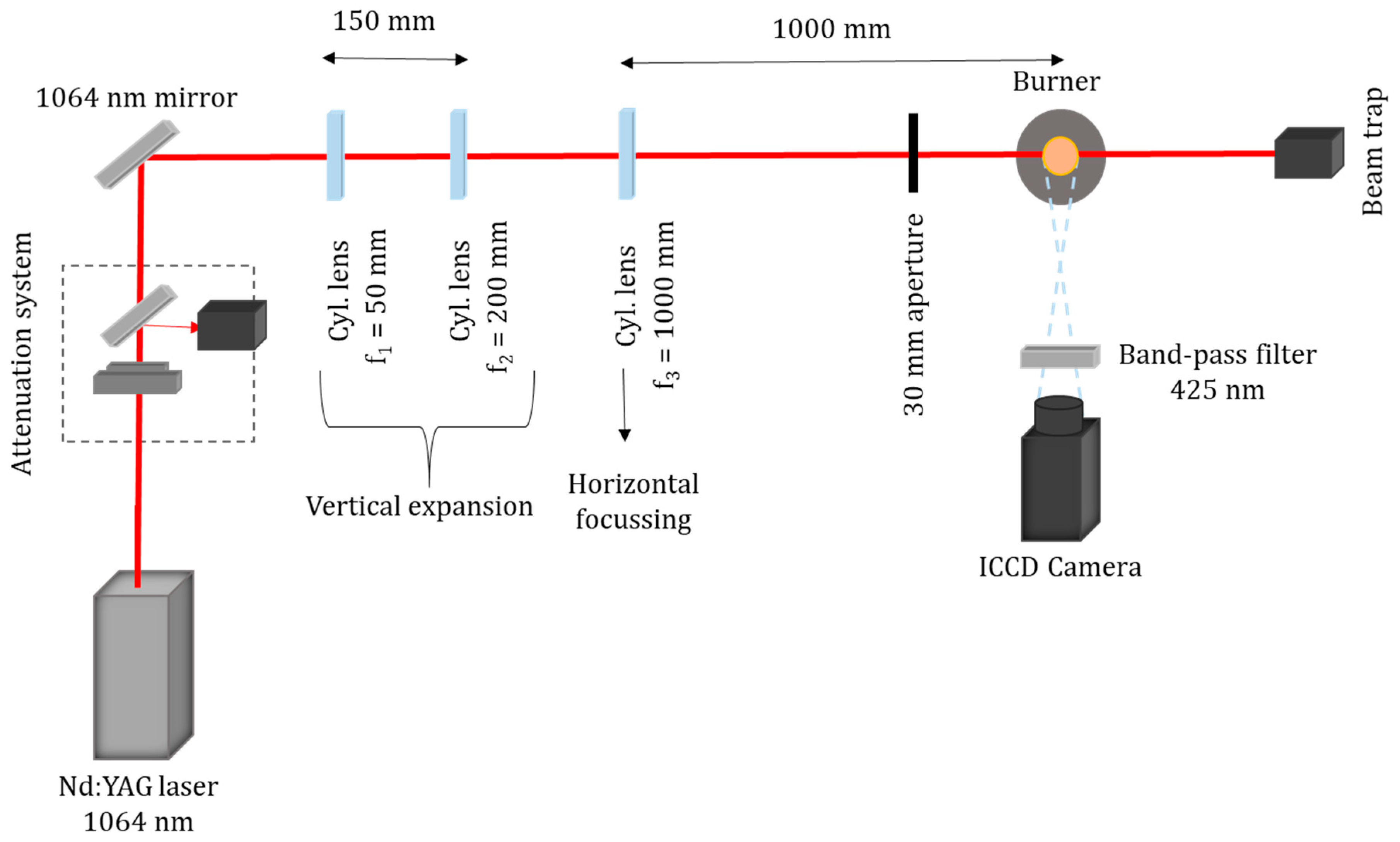
The optical LII set-up is shown in Figure 2. A Q-switched pulsed Nd:YAG laser (Quantel, Q-smart 850), with a repetition rate of 10 Hz and a pulse width of 5 ns was employed as the light source. The fundamental wavelength, 1064 nm, was chosen to avoid interferences with laser-induced fluorescence (LIF) from polycyclic aromatic hydrocarbons. The laser energy is regulated by a combination of a half-wave plate and a thin film polarizer. The beam, 6 mm in diameter, is then shaped into a laser sheet by a series of three cylindrical lenses. The first two lenses, f1 = −50 mm and f2 = 200 mm, expand the beam vertically while the last lens, f = 1000 mm, compresses the beam and focuses it into the flame. Finally, a 30 mm aperture is positioned before the burner, which cuts the edges to ensure that the final beam profile was approximately top hat. This setup generates a laser sheet of 30 mm height and 0.6 mm thickness for 2D-LII measurements. The homogeneity of the laser sheet generated was checked by using a beam profile camera (SP620U Spiricon, OPHIR Photonics). The fluence used is varied between 0.05 and 0.3 J/cm2. The detection system consists of an intensified CCD camera (Andor USB iStar model DH334T-18F-E3, 16 bit) with a resolution of 354 × 301 pixels (maximum resolution 1024 × 1024 pixels). The gate width used is 20 ns while the repetition rate is 10 Hz. A band-pass filter at 425 nm with 50 nm FWHM is employed. For the quantification of the soot volume fraction by LII, the absolute incandescence intensity was calibrated by extinction measurements using a CW laser wavelength (532 nm) on a flat flame from a McKenna burner and, subsequently, compared with the incandescence intensity measured in the diesel burner. From the ratio between the beam intensity before (I0) and after (I) the flame, and knowing the path length of the beam in the flame d, the extinction coefficient Kλ is obtained by
and subsequently the soot volume fraction fv is determined through
Uncertainties in the determination of soot volume fraction are mainly introduced by two factors, namely the value of the absorption function E(m), where m is the complex index of refraction, and the influence of scattering. For E(m), we chose a common value of 0.3 that is generally used for 1064 nm wavelength [46,47,48]. It should be noted that absolute values of fv derived for the diesel burner might be influenced by possible differences in the composition of the soot particles, thus the value of E(m) between the burners used for calibration and measurement. Nonetheless when comparing relative differences in the diesel burner the influence of chemical composition should be small as formation conditions are similar, although an influence can—as a matter of principle—not be ruled out completely [25]. When a collimated beam passes through a volume, its intensity will decrease due to absorption and scattering. For aggregates in a size range of 150–200 nm, the scattering process usually carries between 20% and 30% weight on the overall extinction process [10]. Consequently, after the estimation of the effective aggregates size by WALS measurements, the extinction coefficient was corrected for the scattering, which in this case resulted to be about 22% of the total beam attenuation.
3.3. Wide Angle Light Scattering Set-Up
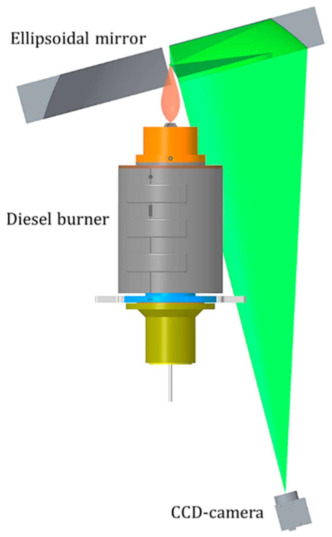
The optical set-up used to adapt the WALS technique to the burner configuration is shown in Figure 3. The ellipsoidal mirror required for WALS measurements can be described as a slice cut out of a spheroid with 32 mm height. The body of the mirror is made out of aluminum, while the reflective surface has an amorphous nickel plating. The distance between the two focal points of the mirror is ∆f = 600 mm and the diameter of the respective plane is 250 mm. Two slits of 10 mm width are placed oppositely to each other in order to allow the beam to pass through. The mirror is positioned above the burner, while the flame generated from the burner is located in the first focal point of the ellipsoidal mirror. The scattered light from the first focal point of the mirror is imaged onto the CCD-camera (AV PIKE F-100B, 1000 × 1000 pixels, 16 bit) by the mirror and a camera lens. An aperture in the second focal point of the mirror defines the size of the measurement volume in the first focal point, which is about 0.3 mm under 90° scattering angle. The exposure time of the camera for the measurements was set to 43 µs. A bandpass filter (535 nm wavelength to compensate the blueshift of the tilted illumination under 12.5°) placed before the lens blocked the ambient light and light from soot luminescence. The camera-mirror system is installed in a rotatable construction and tilted by an angle of 15°, with respect to the vertical axis of the burner, as it can be observed in Figure 4, in order to avoid the signal being completely blocked by the burner. In this manner, the scattered light is collected by one half of the mirror, which contains all the information, while the redundant signal from the other half is discarded. A cw-laser (Qioptiq Nano-250) at 532 nm wavelength, 200 mW, (35 mW used for measurements), is used as the light source. The beam is focused into the measurement volume by a f = 300 mm lens to obtain a small measurement volume with constant flame conditions. The beam polarization is cleaned by a Glan–Taylor prism and adjusted to vertical relative to the mirror plane. The optical set-up had to be calibrated to account for the 1/sin(θ) size dependence of the measurement volume as well as for aberrations caused by the mirror’s surface. For this purpose, calibration measurements on nitrogen molecules, scattering in the Rayleigh regime, were carried out. The irradiation was performed using vertically polarized light; in this manner the scattering of the gas molecules is expected to be isotropic in the scattering plane. For calibration with nitrogen, the laser-power was increased to 200 mW, while the exposure time was increased to 3 s. These settings guarantee sufficient scattering signal as well as constant conditions during a single camera exposure to avoid signal blurring.
4. Results and Discussion
4.1. Determination of Soot Concentration
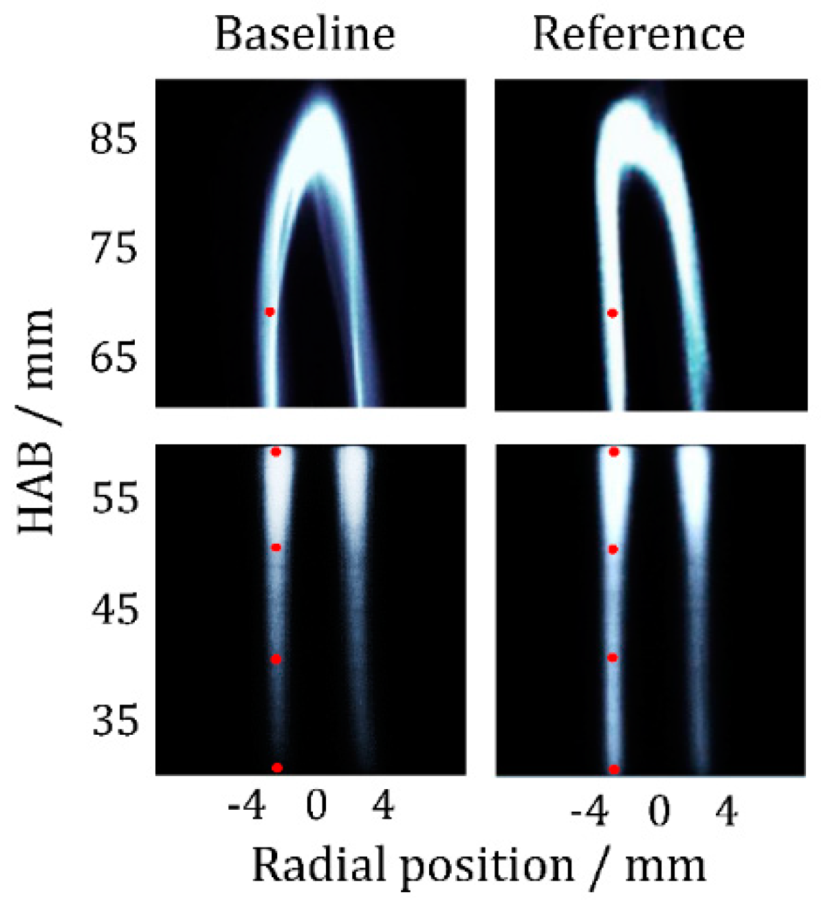
The resulting diesel flame was laminar and sufficiently stable for soot characterization studies. Nevertheless, the flame had minor fluctuations of ±0.7 mm from the central position in the radial direction. For LII measurements, 5000 images were acquired and, after a selection based on symmetry criterion, around 1000 LII images at every height were considered and evaluated to quantify the soot distribution. A background image of the flame with the laser turned off was recorded, accounting for flame luminosity, ambient light, and thermal noise of the camera. LII single-shot images of the reference and baseline diesel flame between 30 and 90 mm height above the burner surface (HAB) are shown in Figure 5, while the averaged images of 1000 LII-single-shots at the same position are shown in Figure 6. The red dots in Figure 6 indicate the location of the WALS measurements.
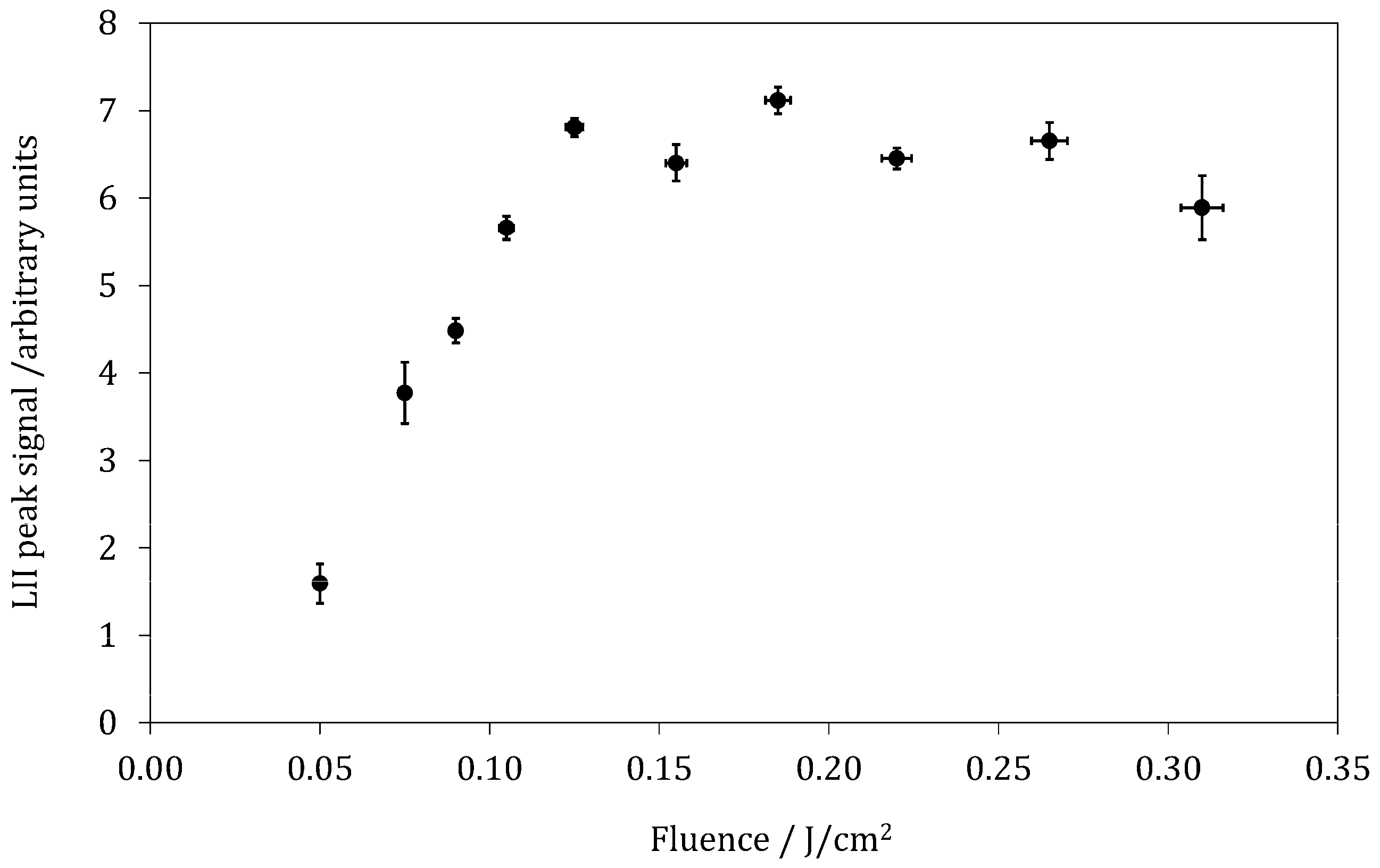
Under flame conditions for pulsed LII, the peak-LII signal typically increased by increasing the fluence until it reached a maximum. In fact, the peak-LII signal started to saturate when the sublimation temperature was reached [49]. For quantitative LII measurements, the prompt LII signal intensity was evaluated. To minimize effects of fluence fluctuations from the laser and laser extinction, first the fluence for a maximum LII signal had to be adjusted. The LII peak behavior as a function of the fluence was; therefore, determined for the diesel flame under study; Figure 7 shows the resulting LII fluence curve. The LII signal was measured at 50 mm above the burner and resulted from the average of 200 single-shot measurements for every fluence. A fluence of 0.15 J/cm2, at the beginning of the plateau region of the curve, was chosen for the subsequent quantitative measurements. At this fluence, the LII peak was barely dependent on the fluence itself, allowing for a proper evaluation of the soot volume fraction.
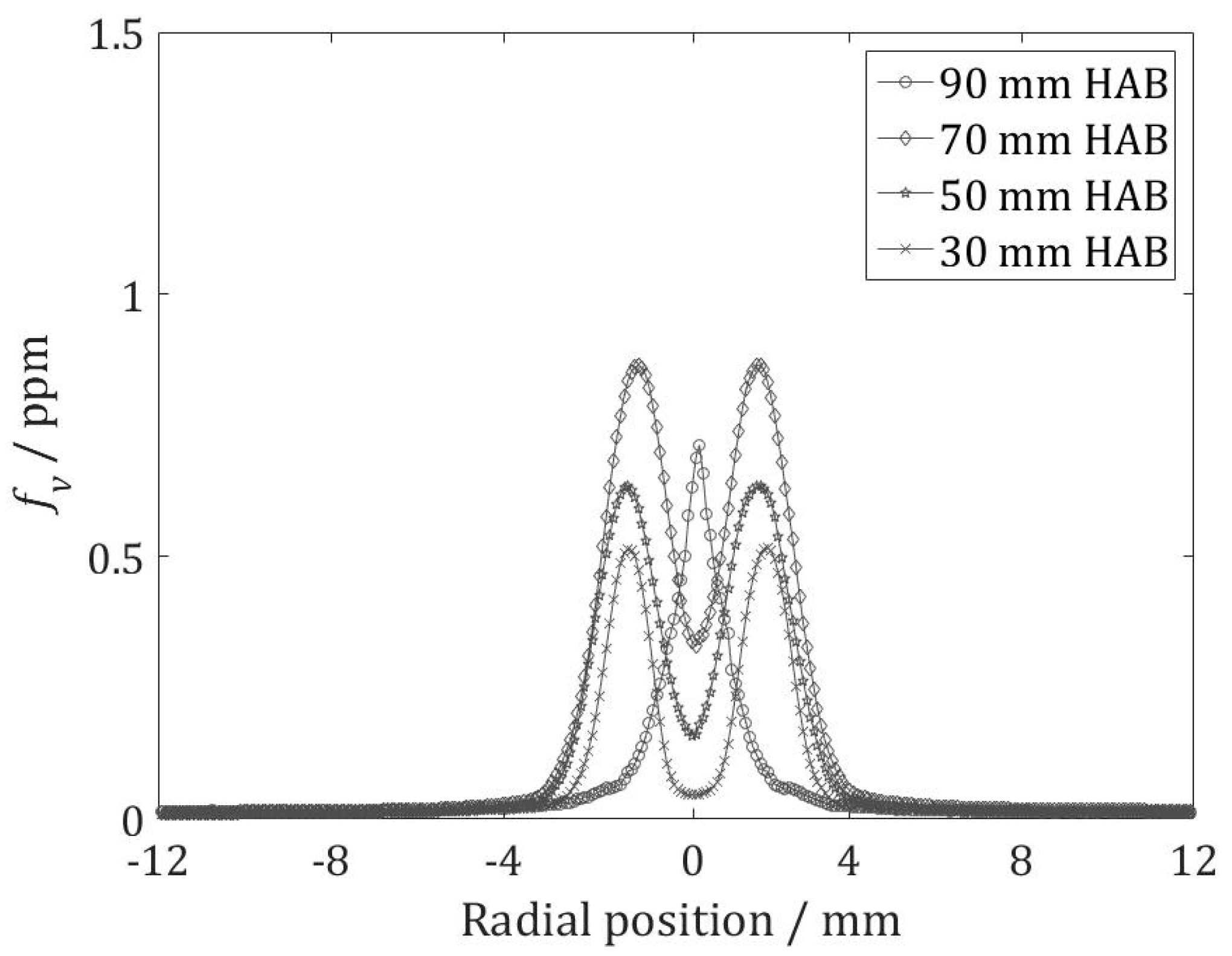
Figure 8 and Figure 9 show the radial soot volume fraction distribution estimated from the averaged LII signal intensity of 1000 single-shot images after calibration by extinction. The measurements were carried out from 30 to 90 mm HAB, in intervals of 10 mm. The overall height of the flame did not change when the fuel was changed; therefore, it was possible to compare the measurements carried out at different heights in the flame between the two fuels. In the chart only 30, 50, 70, and 90 mm were reported. For both fuels, the soot volume fraction reached its maximum in the annular region of the flame, while the central section of the flame exhibited a lower concentration or absence of soot. As expected for diffusion flames, soot was formed in the fuel-rich regions (i.e., below the stoichiometric surface in which fuel and air is perfectly mixed). Accordingly, the LII signal exhibited two peaks in the annular areas, from 30 to 80 mm HAB. The two typical peaks of diffusion flames, which were visible until 80 mm HAB, joined into one peak higher in the flame (i.e., at 90 mm), reflecting the typical “bell” trend of soot in diffusion flames.
It was also observable that for both fuels soot volume fraction increased with increasing HAB, until 80 mm HAB, because of ongoing soot formation. At 90 mm, HAB soot oxidation became dominant; therefore, a reduction of volume fraction occurred. The behavior observed is consistent with data in the literature [50]. The averaged soot volume fraction measured along the width of the flame (~10 mm, from −5 mm to +5 mm) and the maximum fv for the HAB considered, expressed as ppm, are reported in Table S1 in the Supplementary Material. In the diesel flame studied, the maximum fv found was between 1.5 ppm for the baseline diesel and 1.8 ppm for the reference diesel. A more detailed comparison for the two diesel fuels is shown in Figure 10. The combustion of the reference diesel CEC RF-06-03 exhibited between 17% and 40% (depending on the HAB) more soot production with respect to the baseline diesel CEC RF-79-07, especially in the soot formation zone. The error bars, calculated from the standard deviation of the sample distribution, were always below 9%. The two fuels tested had a similar cetane number (52.4 for the reference, 53.3 for the baseline), viscosity, and density (about 2.8 mm2/s at 40 °C for the viscosity and 834 kg/m2 at 15 °C for the density for both fuels). The difference found between the two fuels can be explained by a higher content of aromatic species (mainly mono-aromatics) by about 3% in the CEC RF-06-03 reference diesel. In fact, the phenomenological models of soot formation [51,52,53] postulate that the propensity of a fuel to generate soot is determined mainly by the rate of incipient soot nucleation. The nucleation can involve several paths: Cyclization of chain molecules into rings or dehydrogenation (at low temperatures) of aromatic rings and subsequent formation of polycyclics, as well as breakup and subsequent recyclization of rings at higher temperatures. Fuels with a higher content of aromatic species are; thus, expected to show a higher potential for particle nucleation. As a consequence, also a little difference in aromatics content, like in our case, can cause a significant increase of soot emission, which arises from a growth in the number of soot nucleation paths. Overall flame temperature has a significant impact on the soot formation process. Though it may be assumed that temperatures in the flame were very similar for both fuels, and thus effects resulting from temperature were minor, we also intend to perform temperature measurements in future work.
4.2. Characterization of Morphological Soot Properties
The WALS-measurement technique requires homogeneous flame-properties within the observed measurement volume, a condition not always fulfilled when the flame is flickering. From the ring-shaped scattering data from the CCD-image, scattering data with an angular resolution of 1° is generated. A total of 5000 images of the ring-shaped scattering data were collected from the point-wise measurement volume in the annular region of the flame at the same heights as LII (i.e., from 30 to 70 mm above the burner, every 10 mm; at 80 and 90 mm HAB it was not possible to collect enough data for the evaluation due to the tip fluctuation). As calibrated scattering data from fractal aggregates should monotonously decay with increasing scattering angle, data with positive slope could be discarded. A filter prevented the further evaluation of scattering data that exhibited an increase in intensity between 10° and 90°. For the backward scattering, a less rigorous criterion can be employed as predominantly forward scattering contains the data for the Rg-evaluation. Consequently, between 90° and 170° a larger number of non-decaying data-points (i.e., five) were allowed. Data that passed the filter were evaluated in the Guinier-regime according to Equation (2). Within the 5000 single-images acquired, about 200 images were selected and evaluated for every measurement point. In Figure 11 and Figure 12, one of the single images is shown (Figure 11) in comparison with the corresponding normalized intensity-angle chart. It can be observed that forward scattering is predominant over backward scattering. For the determination of effective aggregate sizes, the measured scattering data I(q) is inverted according to
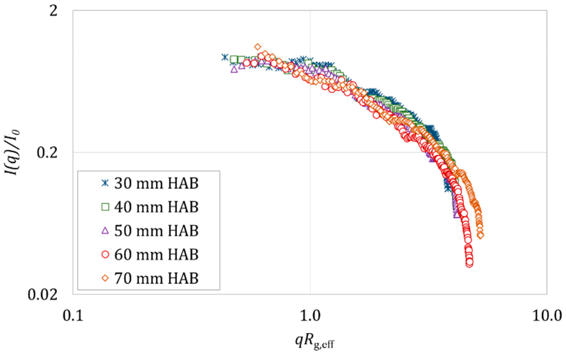
By fitting 1/I(q) against q2 within the limit of the Guinier regime (I(q)/I(0) ≤ 2), the values I(0) and the slope m are obtained and processed to calculate the value of the effective radius of gyration Rg,eff. Figure 12 displays the single-shot scattering data as a function of qRg,eff at different heights in the flame for the reference diesel RF-06-03.
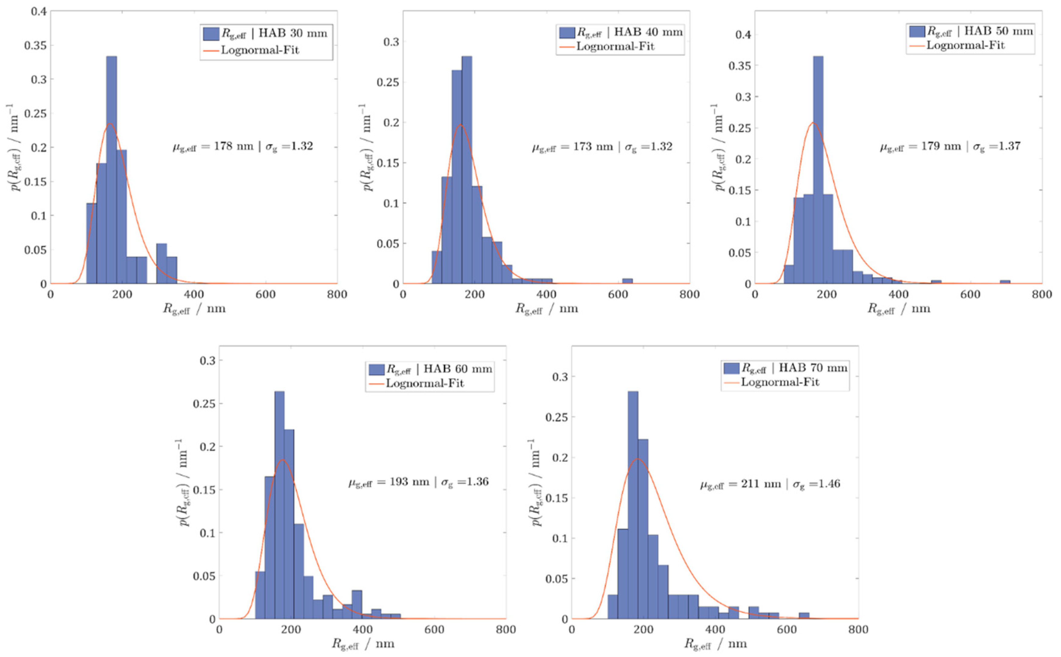
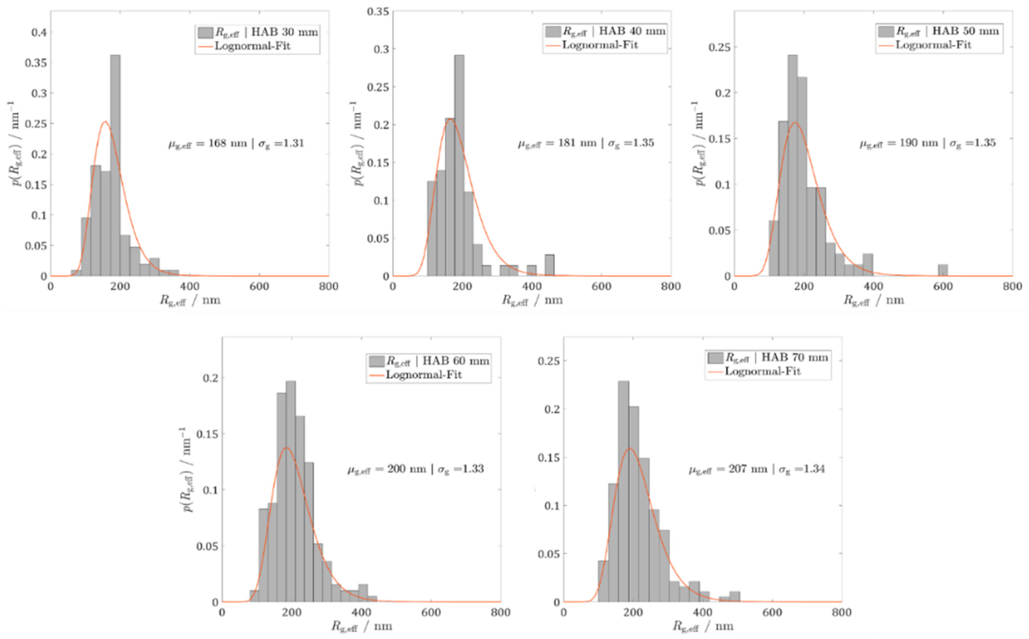
The results for the effective radii of gyration distribution from 30 to 70 mm above the burner for reference and baseline diesel are depicted in Figure 13 and Figure 14, respectively. The statistical distribution of the radii of gyration shows a lognormal shape, which was also observed in slightly turbulent flames [44]. In general, a slight increase of the median µg,eff with increasing HAB can be observed for both fuels, which can be explained by an increasing aggregation time of the particles. As for the reference diesel CECRF-06-03, the median values µg,eff obtained ranged from 178 nm at 30 mm HAB to 211 nm at 70 mm HAB. In the case of the baseline diesel CECRF-79-07, the variation of µg,eff between the lowest height at 30 mm HAB and the upper one at 70 mm HAB is approximately 40 nm.
In Figure 15 the comparison of the median values µg,eff obtained at various HAB for the two fuels under study is reported. To further compare the results, arbitrary subsamples of about 200 are drawn from the full sample at each HAB, yielding a standard deviation of the µg,eff, which on average is 7 nm. Although µg seems to be slightly higher for the baseline diesel between 40 and 60 mm above the burner, within the statistical uncertainty of the results a difference in aggregate size between the two fuels cannot be stated clearly, the aggregation process itself does not seem to alter for the different fuels.
5. Conclusions
A novel prototype of a high-boiling-temperature liquid fuel burner at atmospheric pressure was designed, manufactured, and tested with realistic diesel fuels. The burner was specifically designed to investigate soot formation and, in particular, the influence of the fuel chemical composition on soot formation. For this purpose, the fuel was completely pre-vaporized in order to avoid physical effects on soot formation caused by, for example, spray formation. Soot emission from two diesel fuels, CEC RF-06-03 (reference diesel) and CEC RF-79-07 (baseline diesel), slightly different in chemical composition, were characterized by LII and WALS measurements in the laminar diffusion flame.
The results of the soot quantification at different heights of the flame indicated that with increasing height above the burner, from 30 to 80 mm, soot concentration increased for both fuels; the maximum volume fraction found at 80 mm HAB was 1.76 ppm for the reference and 1.47 ppm for the baseline diesel. After 80 mm HAB, soot oxidizes; therefore, a reduction of soot concentration was observed. As for aggregates size, the radius of gyration (Rg) increased slightly with increasing height above the burner for both reference and baseline diesel. The maximum median of Rg was observed at 70 mm HAB with µg = 211 nm for the reference and µg = 2 07 nm for the baseline; the minimum median was measured at 30 mm HAB, with µg = 178 nm for the reference and µg = 169 nm for the baseline. The comparison of the soot measured in the two diesels showed that the medium radius of gyration did not vary significantly; however, the soot concentration decreased in the baseline diesel flame. This baseline diesel contained a slightly reduced amount of aromatic species leading to the reduction of soot emission, yet the aggregation process was not influenced.
It may be concluded that the novel burner system is capable of producing a sooting non-premixed diesel flame, which forms a suitable basis for the analysis of soot formation for different realistic diesel and other liquid fuels with a high vaporization temperature. Furthermore, the combination of LII and WALS turned out as a suitable tool for the investigation of soot formation in such a burner. Since soot formation in a vapor fuel flame is mainly influenced by the fuel chemical composition, we are now able to single-out the effect of minor changes of fuel chemical composition on soot formation, for example, in the case of diesel additives, which are a promising way to reduce soot emission from engines. Investigations on the influence of diesel additives (which are typically in the range of 1–3 wt.% or even lower) on particle emissions, as well as the analysis of biofuels are planned for future experiments.
Supplementary Materials
The following are available online at https://www.mdpi.com/1996-1073/12/10/1993/s1, Table S1: Maximum and mean fv with the corresponding standard deviations for reference and baseline diesel.
Author Contributions
M.K., N.P. and L.Z. designed the burner; N.P., P.B., M.N.M. performed the experiments; N.P. and F.J.T.H. performed the data evaluation; N.P., P.B., M.N.M., M.K., L.Z., F.J.T.H. and S.W. wrote the paper.
Funding
The financial support from the European Union’s Horizon 2020 research and innovation program under the Marie Skłodowska-Curie grant agreement No. 675528 (Project: IPPAD) is gratefully acknowledged. We acknowledge support by Deutsche Forschungsgemeinschaft and Friedrich-Alexander-Universität Erlangen-Nürnberg (FAU) within the funding program Open Access Publishing.
Acknowledgments
The authors thank Leo Bahr and Simon Aßmann for supporting the measurements and post-processing. Furthermore, the authors thank Afton Chemical Corporation for the supply of the baseline diesel. The authors acknowledge support by Deutsche Forschungsgemeinschaft and Friedrich-Alexander-Universität Erlangen-Nürnberg (FAU) within the funding program Open Access Publishing.
Conflicts of Interest
The authors declare no conflicts of interest.
References
- Bond, T.C.; Doherty, S.J.; Fahey, D.; Forster, P.; Berntsen, T.; DeAngelo, B.; Flanner, M.; Ghan, S.; Kärcher, B.; Koch, D. Bounding the role of black carbon in the climate system: A scientific assessment. J. Geophys. Res. Atmos. 2013, 118, 5380–5552. [Google Scholar] [CrossRef]
- Lemaire, R.; Bejaoui, S.; Therssen, E. Study of soot formation during the combustion of Diesel, rapeseed methyl ester and their surrogates in turbulent spray flames. Fuel 2013, 107, 147–161. [Google Scholar] [CrossRef]
- Khalife, E.; Tabatabaei, M.; Demirbas, A.; Aghbashlo, M. Impacts of additives on performance and emission characteristics of diesel engines during steady state operation. Prog. Energy Combust. Sci. 2017, 59, 32–78. [Google Scholar] [CrossRef]
- Mansurov, Z. Soot formation in combustion processes. Combust. Explos. Shock Waves 2005, 41, 727. [Google Scholar] [CrossRef]
- Karataş, A.E.; Gülder, Ö.L. Soot formation in high pressure laminar diffusion flames. Prog. Energy Combust. Sci. 2012, 38, 818–845. [Google Scholar] [CrossRef]
- Oltmann, H.; Reimann, J.; Will, S. Wide-angle light scattering (WALS) for soot aggregate characterization. Combust. Flame 2010, 157, 516–522. [Google Scholar] [CrossRef]
- Reimann, J.; Kuhlmann, S.-A.; Will, S. 2D aggregate sizing by combining laser-induced incandescence (LII) and elastic light scattering (ELS). Appl. Phys. B 2009, 96, 583–592. [Google Scholar] [CrossRef]
- Wang, Y.; Makwana, A.; Iyer, S.; Linevsky, M.; Santoro, R.J.; Litzinger, T.A.; O’Connor, J. Effect of fuel composition on soot and aromatic species distributions in laminar, co-flow flames. Part 1. Non-premixed fuel. Combust. Flame 2018, 189, 443–455. [Google Scholar] [CrossRef]
- Ni, T.; Pinson, J.; Gupta, S.; Santoro, R. Two-dimensional imaging of soot volume fraction by the use of laser-induced incandescence. Appl. Opt. 1995, 34, 7083–7091. [Google Scholar] [CrossRef]
- Sorensen, C. Light scattering by fractal aggregates: A review. Aerosol Sci. Technol. 2001, 35, 648–687. [Google Scholar] [CrossRef]
- Hong, Z.; Davidson, D.; Vasu, S.; Hanson, R. The effect of oxygenates on soot formation in rich heptane mixtures: A shock tube study. Fuel 2009, 88, 1901–1906. [Google Scholar] [CrossRef]
- Mathieu, O.; Chaumeix, N.; Paillard, C.-E. Soot formation from a distillation cut of a Fischer–Tropsch diesel fuel: A shock tube study. Combust. Flame 2012, 159, 2192–2201. [Google Scholar] [CrossRef]
- Inal, F.; Senkan, S.M. Effects of equivalence ratio on species and soot concentrations in premixed n-heptane flames. Combust. Flame 2002, 131, 16–28. [Google Scholar] [CrossRef] [Green Version]
- D’Anna, A.; Alfe, M.; Apicella, B.; Tregrossi, A.; Ciajolo, A. Effect of fuel/air ratio and aromaticity on sooting behavior of premixed heptane flames. Energy Fuels 2007, 21, 2655–2662. [Google Scholar] [CrossRef]
- Moss, J.; Aksit, I. Modelling soot formation in a laminar diffusion flame burning a surrogate kerosene fuel. Proc. Combus. Inst. 2007, 31, 3139–3146. [Google Scholar] [CrossRef]
- De Andrade Oliveira, M.; Olofsson, N.-E.; Johnsson, J.; Bladh, H.; Lantz, A.; Li, B.; Li, Z.; Aldén, M.; Bengtsson, P.-E.; Luijten, C. Soot, PAH and OH measurements in vaporized liquid fuel flames. Fuel 2013, 112, 145–152. [Google Scholar] [CrossRef]
- Lapuerta, M.; Barba, J.; Sediako, A.D.; Kholghy, M.R.; Thomson, M.J. Morphological analysis of soot agglomerates from biodiesel surrogates in a coflow burner. J. Aerosol Sci. 2017, 111, 65–74. [Google Scholar] [CrossRef]
- Solero, G. Experimental analysis of the influence of inert nano-additives upon combustion of diesel sprays. Nanosci. Nanotechnol. 2012, 2, 129–133. [Google Scholar] [CrossRef]
- Lemaire, R.; Faccinetto, A.; Therssen, E.; Ziskind, M.; Focsa, C.; Desgroux, P. Experimental comparison of soot formation in turbulent flames of diesel and surrogate diesel fuels. Proc. Combus. Inst. 2009, 32, 737–744. [Google Scholar] [CrossRef]
- Du, C.; Andersson, S.; Andersson, M. Two-dimensional measurements of soot in a turbulent diffusion diesel flame: The effects of injection pressure, nozzle orifice diameter, and gas density. Combust. Sci. Technol. 2018, 196, 1659–1688. [Google Scholar] [CrossRef]
- Matti Maricq, M. Physical and chemical comparison of soot in hydrocarbon and biodiesel fuel diffusion flames: A study of model and commercial fuels. Combust. Flame 2011, 158, 105–116. [Google Scholar] [CrossRef]
- Lemaire, R.; Maugendre, M.; Schuller, T.; Therssen, E.; Yon, J. Original use of a direct injection high efficiency nebulizer for the standardization of liquid fuels spray flames. Rev. Sci. Instrum. 2009, 80, 105105. [Google Scholar] [CrossRef] [PubMed]
- Gerstmann, J.; Demetri, E.P.; Jacobs, J.N.; Pickard, D.W. Vaporizing Diesel Burner. Google Patents 5474442, 1991. Available online: https://patents.google.com/patent/US5474442A/en (accessed on 24 May 2019).
- Bryce, D.J.; Ladommatos, N.; Zhao, H. Quantitative investigation of soot distribution by laser-induced incandescence. Appl. Opt. 2000, 39, 5012–5022. [Google Scholar] [CrossRef]
- Michelsen, H.; Schulz, C.; Smallwood, G.; Will, S. Laser-induced incandescence: Particulate diagnostics for combustion, atmospheric, and industrial applications. Prog. Energy Combust. Sci. 2015, 51, 2–48. [Google Scholar] [CrossRef] [Green Version]
- Vander Wal, R.; Weiland, K. Laser-induced incandescence: Development and characterization towards a measurement of soot-volume fraction. Appl. Phys. B 1994, 59, 445–452. [Google Scholar] [CrossRef]
- Shaddix, C.R.; Harrington, J.E.; Smyth, K.C. Quantitative measurements of enhanced soot production in a flickering methane/air diffusion flame. Combust. Flame 1994, 99, 723–732. [Google Scholar] [CrossRef]
- Shaddix, C.R.; Smyth, K.C. Laser-induced incandescence measurements of soot production in steady and flickering methane, propane, and ethylene diffusion flames. Combust. Flame 1996, 107, 418–452. [Google Scholar] [CrossRef]
- Axelsson, B.; Collin, R.; Bengtsson, P.-E. Laser-induced incandescence for soot particle size measurements in premixed flat flames. Appl. Opt. 2000, 39, 3683–3690. [Google Scholar] [CrossRef] [PubMed]
- Walsh, K.T.; Fielding, J.; Smooke, M.D.; Long, M.B. Experimental and computational study of temperature, species, and soot in buoyant and non-buoyant coflow laminar diffusion flames. Proc. Combust. Inst. 2000, 28, 1973–1979. [Google Scholar] [CrossRef] [Green Version]
- McEnally, C.S.; Pfefferle, L.D. Improved sooting tendency measurements for aromatic hydrocarbons and their implications for naphthalene formation pathways. Combust. Flame 2007, 148, 210–222. [Google Scholar] [CrossRef]
- Vander Wal, R.L.; Jensen, K.A.; Choi, M.Y. Simultaneous laser-induced emission of soot and polycyclic aromatic hydrocarbons within a gas-jet diffusion flame. Combust. Flame 1997, 109, 399–414. [Google Scholar] [CrossRef]
- Das, D.D.; McEnally, C.S.; Pfefferle, L.D. Sooting tendencies of unsaturated esters in nonpremixed flames. Combust. Flame 2015, 162, 1489–1497. [Google Scholar] [CrossRef] [Green Version]
- Reimann, J.; Will, S. Optical diagnostics on sooting laminar diffusion flames in microgravity. Micrograv. Sci. Technol. 2005, 16, 333–337. [Google Scholar] [CrossRef]
- Kock, B.F.; Tribalet, B.; Schulz, C.; Roth, P. Two-color time-resolved LII applied to soot particle sizing in the cylinder of a Diesel engine. Combust. Flame 2006, 147, 79–92. [Google Scholar] [CrossRef]
- Schraml, S.; Will, S.; Leipertz, A. Simultaneous Measurement of Soot Mass Concentration and Primary Particle Size in the Exhaust of a DI Diesel Engine by Time-Resolved Laser-Induced Incandescence (TIRE-LII); 0148-7191; SAE Technical Paper; SAE: Warrendale, PA, USA, 1999. [Google Scholar]
- Wiltafsky, G.; Stolz, W.; Köhler, J.; Espey, C. The Quantification of Laser-Induced Incandescence (LII) for Planar Time Resolved Measurements of the Soot Volume Fraction in a Combusting Diesel Jet; 0148-7191; SAE Technical Paper; SAE: Warrendale, PA, USA, 1996. [Google Scholar]
- Sorensen, C.; Cai, J.; Lu, N. Light-scattering measurements of monomer size, monomers per aggregate, and fractal dimension for soot aggregates in flames. Appl. Opt. 1992, 31, 6547–6557. [Google Scholar] [CrossRef]
- Santoro, R.; Semerjian, H.; Dobbins, R. Soot particle measurements in diffusion flames. Combust. Flame 1983, 51, 203–218. [Google Scholar] [CrossRef]
- Puri, R.; Richardson, T.; Santoro, R.; Dobbins, R. Aerosol dynamic processes of soot aggregates in a laminar ethene diffusion flame. Combust. Flame 1993, 92, 320–333. [Google Scholar] [CrossRef]
- Hull, P.; Shepherd, I.; Hunt, A. Modeling light scattering from diesel soot particles. Appl. Opt. 2004, 43, 3433–3441. [Google Scholar] [CrossRef] [PubMed]
- Sorensen, C.; Wang, G. Size distribution effect on the power law regime of the structure factor of fractal aggregates. Phys. Rev. E 1999, 60, 7143. [Google Scholar] [CrossRef]
- Huber, F.J.; Will, S.; Daun, K.J. Sizing aerosolized fractal nanoparticle aggregates through Bayesian analysis of wide-angle light scattering (WALS) data. J. Quant. Spectrosc. Radiat. Transf. 2016, 184, 27–39. [Google Scholar] [CrossRef]
- Oltmann, H.; Reimann, J.; Will, S. Single-shot measurement of soot aggregate sizes by wide-angle light scattering (WALS). Appl. Phys. B 2012, 106, 171–183. [Google Scholar] [CrossRef]
- Di Blasi, C. Modeling chemical and physical processes of wood and biomass pyrolysis. Progr. Energy Combust. Sci. 2008, 34, 47–90. [Google Scholar] [CrossRef]
- Maffi, S.; De Iuliis, S.; Cignoli, F.; Zizak, G. Investigation on thermal accommodation coefficient and soot absorption function with two-color Tire-LII technique in rich premixed flames. Appl. Phys. B 2011, 104, 357–366. [Google Scholar] [CrossRef]
- Eremin, A.; Gurentsov, E.; Popova, E.; Priemchenko, K. Size dependence of complex refractive index function of growing nanoparticles. Appl. Phys. B 2011, 104, 285–295. [Google Scholar] [CrossRef]
- Snelling, D.R.; Liu, F.; Smallwood, G.J.; Gülder, Ö.L. Determination of the soot absorption function and thermal accommodation coefficient using low-fluence LII in a laminar coflow ethylene diffusion flame. Combust. Flame 2004, 136, 180–190. [Google Scholar] [CrossRef]
- Olofsson, N.-E.; Simonsson, J.; Török, S.; Bladh, H.; Bengtsson, P.-E. Evolution of properties for aging soot in premixed flat flames studied by laser-induced incandescence and elastic light scattering. Appl. Phys. B 2015, 119, 669–683. [Google Scholar] [CrossRef]
- De Iuliis, S.; Cignoli, F.; Zizak, G. Two-color laser-induced incandescence (2C-LII) technique for absolute soot volume fraction measurements in flames. Appl. Opt. 2005, 44, 7414–7423. [Google Scholar] [CrossRef]
- Frenklach, M. Reaction mechanism of soot formation in flames. Phys. Chem. Chem. Phys. 2002, 4, 2028–2037. [Google Scholar] [CrossRef]
- Johansson, K.; Head-Gordon, M.; Schrader, P.; Wilson, K.; Michelsen, H. Resonance-stabilized hydrocarbon-radical chain reactions may explain soot inception and growth. Science 2018, 361, 997–1000. [Google Scholar] [CrossRef] [PubMed] [Green Version]
- Schulz, F.; Commodo, M.; Kaiser, K.; De Falco, G.; Minutolo, P.; Meyer, G.; Andrea, D.; Gross, L. Insights into incipient soot formation by atomic force microscopy. Proc. Combust. Inst. 2019, 37, 885–892. [Google Scholar] [CrossRef]
Figure 1.
Schematic design of the laminar burner for diesel vaporization and combustion.

Figure 2.
Schematic top-view of the optical set-up for 2D-LII measurements.

Figure 3.
Schematic side-view of the optical set-up for WALS measurements.

Figure 4.
Rotatable camera-mirror system. Camera, mirror, and optical set-up are tilted by 15° with respect to the vertical axis of the burner. In this way the signal collected by half of the mirror is imaged into the camera without being blocked by the burner itself.
Figure 4.
Rotatable camera-mirror system. Camera, mirror, and optical set-up are tilted by 15° with respect to the vertical axis of the burner. In this way the signal collected by half of the mirror is imaged into the camera without being blocked by the burner itself.

Figure 5.
Single-shot raw LII images of the laminar non-premixed flame obtained from the combustion of the reference and the baseline diesel.
Figure 5.
Single-shot raw LII images of the laminar non-premixed flame obtained from the combustion of the reference and the baseline diesel.

Figure 6.
Mean LII images, average of 1000 single-shots.

Figure 7.
LII peak signal versus fluence curve. The vertical error bars are obtained from the standard deviation of the 1000 LII single-shot images evaluated, while the horizontal error bars are the standard deviation of the laser fluence.
Figure 7.
LII peak signal versus fluence curve. The vertical error bars are obtained from the standard deviation of the 1000 LII single-shot images evaluated, while the horizontal error bars are the standard deviation of the laser fluence.

Figure 8.
Comparison of soot volume fraction (fv) radial profiles at 30, 50, 70, and 90 mm for the reference diesel.
Figure 8.
Comparison of soot volume fraction (fv) radial profiles at 30, 50, 70, and 90 mm for the reference diesel.

Figure 9.
Comparison of soot volume fraction (fv) radial profiles at 30, 50, 70, and 90 mm for the baseline diesel.
Figure 9.
Comparison of soot volume fraction (fv) radial profiles at 30, 50, 70, and 90 mm for the baseline diesel.

Figure 10.
Comparison of the maximum fv measured for the reference diesel and baseline diesel between 30 and 90 mm above the burner (HAB), with corresponding standard deviations.
Figure 10.
Comparison of the maximum fv measured for the reference diesel and baseline diesel between 30 and 90 mm above the burner (HAB), with corresponding standard deviations.

Figure 11.
Single-shot calibrated image of half (0–180°) of the ring-shaped WALS scattering data (left) and the corresponding normalized scattering intensity (right).
Figure 11.
Single-shot calibrated image of half (0–180°) of the ring-shaped WALS scattering data (left) and the corresponding normalized scattering intensity (right).

Figure 12.
Comparison of single-shot scattering data versus qRg,eff from 30 to 70 mm above the burner. The scattering data can be evaluated in the Guinier regime.
Figure 12.
Comparison of single-shot scattering data versus qRg,eff from 30 to 70 mm above the burner. The scattering data can be evaluated in the Guinier regime.

Figure 13.
Distribution of the effective Rg,eff at 30, 40, 50, 60, and 70 mm HAB for the reference diesel CEC RF-06-03.
Figure 13.
Distribution of the effective Rg,eff at 30, 40, 50, 60, and 70 mm HAB for the reference diesel CEC RF-06-03.

Figure 14.
Distribution of the effective Rg,eff at 30, 40, 50, 60, and 70 mm HAB for the baseline diesel CEC RF-79-07.
Figure 14.
Distribution of the effective Rg,eff at 30, 40, 50, 60, and 70 mm HAB for the baseline diesel CEC RF-79-07.

Figure 15.
Comparison of the median Rg (µg,eff) found at the different HABs investigated for the reference diesel and the baseline diesel.
Figure 15.
Comparison of the median Rg (µg,eff) found at the different HABs investigated for the reference diesel and the baseline diesel.

© 2019 by the authors. Licensee MDPI, Basel, Switzerland. This article is an open access article distributed under the terms and conditions of the Creative Commons Attribution (CC BY) license (http://creativecommons.org/licenses/by/4.0/).
Share and Cite
MDPI and ACS Style
Palazzo, N.; Kögl, M.; Bauer, P.; Mannazhi, M.N.; Zigan, L.; Huber, F.J.T.; Will, S. Investigation of Soot Formation in a Novel Diesel Fuel Burner. Energies 2019, 12, 1993. https://doi.org/10.3390/en12101993
AMA Style
Palazzo N, Kögl M, Bauer P, Mannazhi MN, Zigan L, Huber FJT, Will S. Investigation of Soot Formation in a Novel Diesel Fuel Burner. Energies. 2019; 12(10):1993. https://doi.org/10.3390/en12101993
Chicago/Turabian StylePalazzo, Natascia, Matthias Kögl, Philipp Bauer, Manu Naduvil Mannazhi, Lars Zigan, Franz Johann Thomas Huber, and Stefan Will. 2019. "Investigation of Soot Formation in a Novel Diesel Fuel Burner" Energies 12, no. 10: 1993. https://doi.org/10.3390/en12101993
Note that from the first issue of 2016, this journal uses article numbers instead of page numbers. See further details here.