Toolface Control Method for a Dynamic Point-the-Bit Rotary Steerable Drilling System


1
College of Information and Control Engineering, China University of Petroleum, Qingdao 266580, China
2
School of Petroleum Engineering, China University of Petroleum, Qingdao 266580, China
*
Author to whom correspondence should be addressed.
Energies 2019, 12(10), 1831; https://doi.org/10.3390/en12101831
Submission received: 14 April 2019
/
Revised: 4 May 2019
/
Accepted: 7 May 2019
/
Published: 14 May 2019
(This article belongs to the Section F: Electrical Engineering)
Abstract
:In the dynamic point-the-bit rotary steerable system (DPRSS), a high dynamic stiffness toolface control method is desired to ensure the stabilized platform traces the directional command accurately and quickly. A three-loop compound toolface control method using the Model-based Active Disturbance Rejection Control (MADRC) algorithm is presented, and a load torque estimator and an outer housing speed estimator are designed based on system model to obtain the external disturbances. The proposed toolface control method was verified by numerical simulation and DPRSS prototype testing, and its speed loop frequency responses are analyzed. The results reveal that this method is effective in disturbance rejection and robust against parameter uncertainties, and the MADRC shows better performance compared with the conventional ADRC and the proportional-integral (PI) controller. The proposed method has the potential to be used in harsh drilling conditions.
1. Introduction
Directional drilling technology is the science of deviating a borehole along a predefined path. With the growing demands of new oil and gas drilling technology, the traditional drilling equipment has difficulty in covering these demands. The rotary steerable system (RSS) is the latest technology that improves drilling accuracy and increases the rate of penetration [1,2].
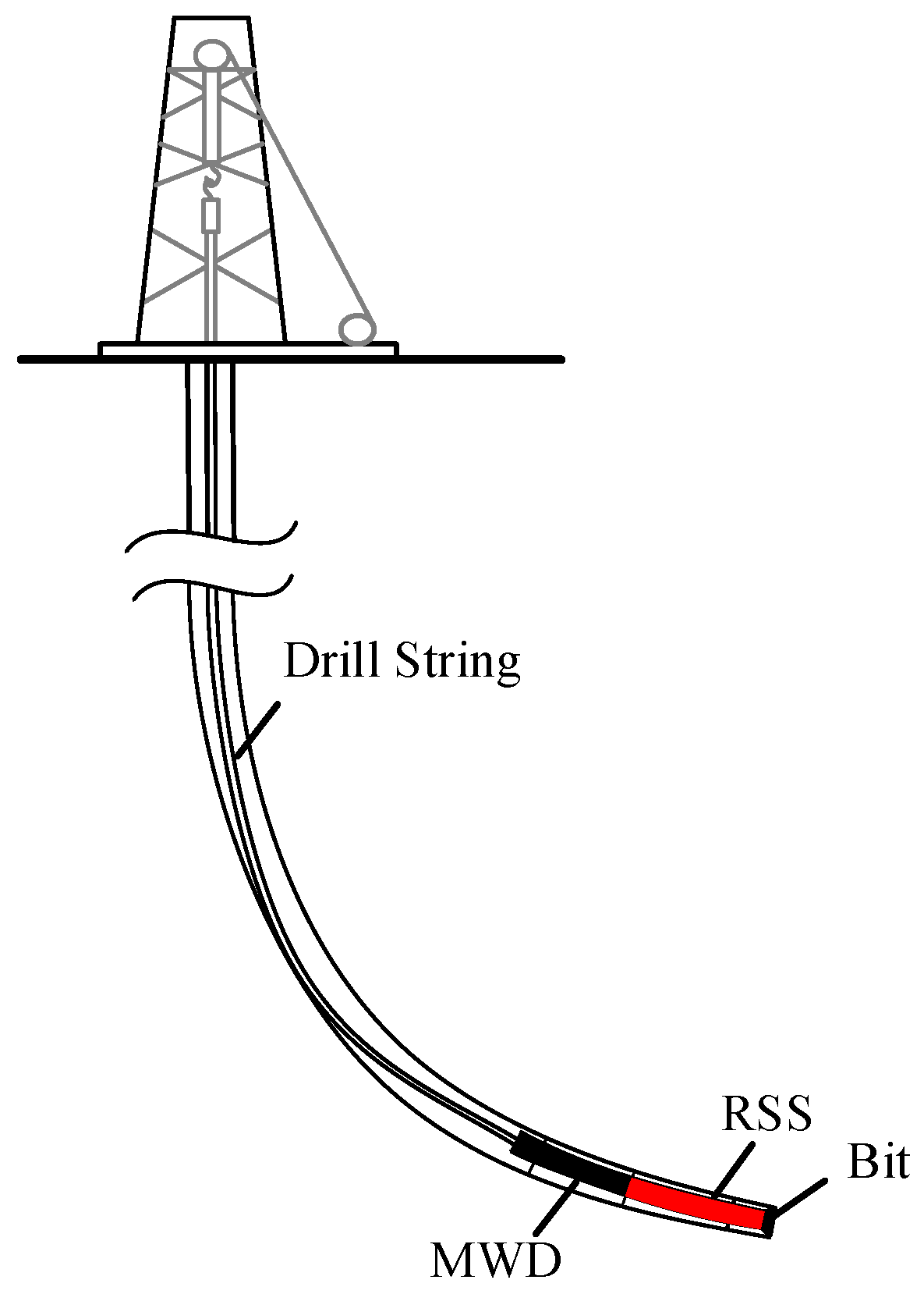
As can be seen in Figure 1, the downhole drilling equipment consists of the drill string, the measurement while drilling (MWD) instrument, the RSS, and the drilling bit. The drill string applies the drilling torque and the weight on bit (WOB), the MWD is used for real-time drilling parameters measurement, and the RSS connects to the bit and changes the bit orientation directly.
The bit direction is described by an angle named the toolface. Generally, the RSS has two essential parts: the first one, named the bit steering unit, is used to apply steering force to the bit; the other one, named the geostationary unit, is used to determine the toolface while the drilling string is rotating. Two kinds of steering units are used, the first one applies a side force to the borehole by three pads, which is known as ‘push-the-bit,’ and the second one uses a dual-eccentric ring to change the bit steering directly, which is called ‘point-the-bit.’ The second one is of particular interest because its performance is independent of formation quality. There are also two kinds of geostationary units, the first one having an independent outer housing which does not rotate or rotates very slowly relative to the drilling string, called ‘static RSS’, and the second one is known as ‘dynamic RSS’, having a closed-loop-controlled stabilized platform which is geostationary while the drilling string is rotating [3]. Based on the combination of the steering units and geostationary units, four kinds of directional drilling tools are developed.
This paper focuses on the dynamic point-the-bit rotary steerable system (DPRSS), its geostationary unit is a motor-driven stabilized platform, and the steering unit is fixed at one end of the platform. Hence, the toolface is operated by changing the stabilized platform angular position [4]. The steering accuracy of DPRSS is determined by the performance of the stabilized platform control system. However, the downhole disturbances, such as the load torque and the outer housing speed, create additional challenges to the controller design [3,5,6,7,8,9].
The structure of the RSS toolface control method is summarized in Figure 2, and it is also suitable for our DPRSS. The control method consists of four loops from inside to outside, namely, the current loop, the motor speed loop, the stabilized platform speed loop, and the toolface loop. The motor is described by the transfer function, where is the Laplace operator, and are the motor stator resistance and inductance, is the torque constant, is the coefficient of counter electromotive force, is the total inertia of the stabilized platform and the motor, and is the viscous coefficient. , and denote the toolface, motor speed, and motor current, respectively. The load torque is the disturbance of the motor speed loop, and the outer housing rotary speed is the disturbance of the stabilized platform speed loop. Both the current loop and motor speed loop are designed to improve motor performance. The stabilized platform speed loop is to suppress outer housing speed fluctuations, and the toolface loop is used to track the toolface reference.
Different structures in Figure 2 have been used in RSS, e.g., a three–loop structure without a stabilized platform speed loop was suggested by Tang [10] and Zhang [11]. The performance of the three–loop and four–loop structure using proportional-integral (PI) controllers was compared in [12], with the help of stabilized platform speed loop, the four–loop system has better outer housing speed rejection performance, but the four–loop structure is complex since there are four controllers that need to be tuned.
The control algorithm is another key factor for system performance. Controllers based on PID [3,7,10,13], sliding mode control [5,14] and intelligent control [11] have been studied in the other types of RSS drilling system, however, the DPRSS disturbances are time-varying with uncertainties, the traditional PID algorithm cannot achieve high performance, and the others are too dependent on mathematical models or too complex to implement on the downhole hardware.
The ADRC is an emerging technology proposed by Han [15]. It has been adopted by the motor control system to cope with vast uncertainties [16,17,18] and it is easy for downhole hardware implementation. The ADRC can be designed model–independent, which is called conventional ADRC (CADRC). Meanwhile, the model information can also be used in the ADRC algorithm, which is called model–based active disturbance rejection control (MADRC). In our system, parts of the DRPSS dynamics are known, which can be separated from the ESO to reduce estimation burden. In this way, the toolface tracking performance can be improved.
In this paper, a three-loop compound toolface control system using the MADRC algorithm is proposed. The stabilized platform is driven by a permanent magnet synchronous motor (PMSM), and the field–oriented control (FOC) technique is applied. The theoretical model of the stabilized platform is studied, a load torque estimator and an outer housing speed estimator are presented, based on the system model, and the toolface MADRC controller and motor speed MADRC controller are designed. The proposed toolface control method was verified by simulation and tested by a DPRSS prototype under several typical drilling modes, including normal drilling, sticking, and the stick-slipping. The controller robustness against parameter uncertainties and the toolface response performance were analyzed and simulated. For comparison, the CADRC and PI algorithms were also implemented in simulation and experimental tests. The proposed control method shows satisfactory performance and its application in actual drilling operation would be explored in future work.
This paper is organized as follows: Section 2 includes the DPRSS working principle description and stabilized platform modeling. Section 3 provides a short review of the MADRC algorithm and shows a comprehensive explanation of the proposed toolface control method. Section 4 provides the simulation and prototype test results. Section 5 provides the conclusion and future work.
2. The DPRSS Working Principle and Modeling of the Stabilized Platform
2.1. DPRSS Working Principle
In Figure 3, plane Ῥ is perpendicular to the wellbore axis, point A is the top of plane Ῥ, and point B is the intersection of the bit axis and plane Ῥ. The line is named the high side; the angle between and is the toolface, and it is denoted by . The toolface is defined between 0 and 360 deg, which represents the intended drilling direction. The DPRSS consists of four fundamental parts: the outer housing, the stabilized platform, the bit shaft, and the universal joint. The outer housing connects to the drill string and rotates at the same speed as it. The drilling torque and the WOB are transmitted from outer housing to bit through the universal joint. The steering unit is assembled on the stabilized platform, and the bit shaft connects eccentrically to the steering unit.
The stabilized platform is the core part of DPRSS, it is equipped with an angular position control system and remains nearly geostationary while the outer housing is rotating. The desired toolface is achieved by changing the stabilized platform angular position. It is clear that the DPRSS bit steering precision highly depends on the stabilized platform toolface control performance.
In drilling engineering, the toolface is monitored by the field engineer, and the desired toolface is updated based on the formation characteristics. According to the field engineer experience, the DPRSS toolface tracking error should be less than ±15 deg, otherwise the bit cannot reach the target reservoir successfully.
2.2. The Stabilized Platform Modeling
In the synchronous d–q frame, the PMSM mathematical model is:
where and , and , and denote the stator voltage, stator current, and the stator winding inductance of the d–axis and q–axis, respectively. is the stator winding resistance, is the permanent magnet flux, and is the number of pole pairs.
The PMSM is a complex nonlinear system with multi-variables and strong coupling. By applying the field oriented control (FOC) technique, the controller is designed to keep nearly zero, and then the torque- and flux-producing components are approximately decoupled; the PMSM electromagnetic torque is only related to the q–axis motor current [19]:
where is the motor torque constant. In this case, the PMSM model is simplified, and its torque can be controlled by an controller.
Based on Newton’s 2nd law for rotation, the stabilized platform kinematic equation is:
where , , , , and are the PMSM electromagnetic torque, load torque, friction factor, static friction torque, and total inertia, respectively, is a unit transform factor, and the term denotes the viscous friction torque.
Considering the toolface is determined by the outer housing speed and motor speed , from the DPRSS structure shown in Figure 3, we can obtain:
Considering , , and are constants, the toolface is linearly related to and , the drilling dynamics are considered in terms of the load torque and the outer housing speed, which are nonlinear and time-varying. The load torque and outer housing speed are difficult to measure immediately, hence, they are treated as disturbances in the control system design.
3. DPRSS Toolface Control Method
The q–axis current, motor speed, and toolface are controlled separately using a three–loop compound structure. In this way, we reduce the stabilized platform to three first–order objects, and then, the MADRC algorithm is applied in the motor speed loop and toolface loop to achieve high dynamic performance in the overall operating range.
3.1. MADRC Framework and Algorithm
The MADRC diagram is shown in Figure 4, and consists of four items: the tracking differentiator (TD), the extend state observer (ESO), the state error feedback (SEF) control law, and the model–based compensation (MC). The ESO is used to estimate the total unknown disturbances; the SEF generates to restrain the residual error and achieve the desired control goal; the TD is to arrange the transition process, and it can be omitted in the first-order system. The three items mentioned above constitute the CADRC [15]. The MC, which generates the estimation of available disturbance value , is an improvement of the CADRC, and it needs to be designed based on the object model.
Considering a typical first–order single–input single–output system:
where is the output, the is the real–valued function of the state , is the external disturbance, is the control input. Owing to uncertainties, it is hard to fully know the and the , but we can separate the known part from them. Rewrite (5) as
where represents the unknown object dynamics and external disturbances, which are called total unknown disturbances, the parameter uncertainties are also included in . denotes the known dynamics and external disturbances, and is obtained by the MC.
Considering as an augmented state, we can write Equation (6) as:
In Equation (7), the is the augmented state, according to [20], the states of the augmented first–order system in Equation (7) are observable. Then, the unique ESO for Equation (7) is:
where and are the estimation values of and , and and are the observer gains. Compared with the CADRC, which treats all dynamics and external disturbances as unknown, the MADRC separates from the ESO output , which lightens the ESO burden. This is helpful to reduce the ESO estimation error. The nonlinear function is [15]:
The function plays an important role in the ADRC framework, it has both linear and nonlinear region, its linear region is to prevent high–frequency chattering. It is obvious that Equation (8) is in the form of classical Luenberger observer when , and it is in the form of a variable structure observer when . Generally, the ADRC adopts , in this case, the ESO does not converge to sliding mode but to the ‘self–stable region’, it also yields relatively high gain when the error is small and small gain when the error is large [21]. The gains and are determined based on observer cut–off frequency [22,23]:
With the ESO properly designed, is expected to converge to the unknown disturbance , Equation (5) can now be dynamically compensated with:
Substituting Equation (7) into Equation (6):
It is clear that the object is reduced to an approximate unit–gain integrator transfer function, which is easy to be controlled by the following SEF:
where is the reference, is determined by closed loop cut–off frequency. The nonlinear function generates a large equivalent controller gain while is small, and vice versa. The nonlinear control law has been proved to be more efficient than the linear one [21].
3.2. Load Torque and Outer Housing Speed Estimators
The typical value of total inertia, friction factor, and static friction are determined based on the motor parameter and the DPRSS structure, but the load torque and outer housing speed are immeasurable and need to be estimated.
Considering the and are obtained by sensors, the load torque can be estimated by:
A low–pass filter is used to suppress the high–frequency noise, and then, the estimator is shown as:
where is the time constant of low pass filter. The discrete load observer using the backward Euler’s method is:
where is the estimator output, h is the sample period, is the sample time, and are two intermediate variables. Although the larger leads to better estimation performance in the steady state, the observer dynamic response becomes slow. depends on the application requirements; in our application, is 0.001 s.
In addition to the load torque, the outer housing speed is still unknown. Owing to the limitation of DPRSS structure, it is hard to install sensors on the outer housing. Considering that is easily obtained by installing a gyro inside the stabilized platform sensor package, we utilize Equation (4) to estimate the outer housing speed :
3.3. Design of the DPRSS Toolface Control Method
The toolface control method block diagram is shown in Figure 5. Considering that the current loop can be designed the same as the controller, the current loop is omitted in Figure 5. The PMSM is also described by transfer function to meet an agreement with Figure 2, and the coefficient of counter electromotive force is . The subscripts m and t denote the speed loop terms and toolface loop terms, respectively.
The current loop controller adopts the PI algorithm, its controller parameters were tuned by the frequency domain design method. The motor speed loop and the toolface loop adopt the MADRC algorithm.
Define states and , we rewrite Equation (3) as:
where is a constant. in Equation (3) is replaced by the current loop reference , and denotes the total unknown disturbances. is the speed loop MC, which is designed as:
By applying the linear formation of , where , the speed loop ESO is:
Let , then, the error equation of Equation (20) is:
The roots of the characteristic polynomial of are , which are all in the left half plane, considering comes from a physical system which varies continuously, the is bounded, then, it is obvious that the speed loop ESO is bounded–input bound–output stable, the can be estimated.
The linear formation of is also used in the speed loop SEF design, which is given by:
Once the speed loop MADRC controller is designed, we use instead of . Define states , , and then, the state equation of Equation (4) is:
where the is a constant. The MC of the toolface MADRC controller is:
Remark 1: Equation (24) combines gyro measurements in the toolface loop, comparing with the direct use of gyro measurements, for example, the stabilized platform speed control loop [12], the gyro turns into an auxiliary measurements in the proposed toolface control loop, the gyro drift is lumped in the unknown disturbance and estimated by ESO, and then the gyro drift effect is reduced.
The nonlinear is applied in the toolface loop to improve control performance, the ESO and SEF are given by:
Assuming is bounded, which is reasonable in the DRPSS application because its disturbances can be treated as continuously varying, then, referring to [24], the steady–state errors of the toolface loop ESO are and , it is obvious that the ESO estimation errors are bounded.
For DPRSS applications, the reference signal mainly remains constant, the disturbances come from the physical system and varies continuously, then, the external disturbances, the reference signal, and their derivatives are all bounded; hence, the toolface control system is convergent [23,25], but its performance depends on the controller parameters.
4. Simulation and DPRSS Prototype Experiment
The numerical simulation and DPRSS prototype experiments were performed to verify the controller performance, besides the proposed toolface control method, the CADRC strategy and the PI algorithm were also used for comparison. The CADRC strategy was realized by deleting the and terms in the MADRC.
The control method simulation was carried out, the controller robustness against parameter uncertainties and the toolface response performance in the presence of various disturbances were presented. Then, the control method was implemented on the DPRSS prototype to test its capability. The typical values of PMSM parameter, which were used in the simulation, load torque estimator, and speed loop MADRC controller, are shown in Table 1.
4.1. Toolface Control Method Simulation
As shown in Figure 6, the control method was simulated by Simulink software. The current loop and PMSM were combined in one block. The speed loop control algorithm and the toolface loop control algorithm were performed by different blocks. The load torque disturbance was simulated as follows [11]:
where is the steering torque, and denotes the eccentric torque which is caused by the eccentrically located receptacle of steering unit.
The outer housing speed is the primary disturbance and it is time-varying. Particularly, the stick-slip condition which is a periodic stopping (sticking) and overshooting (slipping) of the angular velocity is considered, it is caused by the drilling assembly stick-slip torsional vibration. Typically, the stick-slip baseband frequency is less than 3.14 rad/s [26], and the peak bit rotation rate may be several times that of the operating rotation rate.
The controllers were tuned based on the method presented in [22]. is a constant, and can be calculated using the motor parameter, the other parameters need to be tuned based on the disturbance characteristics. The ESO gains cannot be smaller than the closed loop cut–off frequency, and it is known that the higher bandwidth leads to better controller tracking performance. However, it cannot be too large to ensure the control signal under physical limits, such as the motor rated current and rated speed limitations. Considering the toolface loop bandwidth should be larger than 3.14 rad/s to suppress stick-slip disturbance, and the motor speed loop cut–off frequency can be selected 10–20 times that of the toolface loop, we selected the as the initial values, then, the and were increased step by step until the control signal reached the physical limits. Following such a tuning procedure, the toolface loop controller was tuned by setting as the initial values. The final controller parameters are shown in Table 2.
4.1.1. The Motor Speed Loop Simulation
The motor speed loop was simulated firstly. The motor speed controller sampling time was 0.5 ms. The CADRC and a well–tuned PI controller were also employed for comparison, and the CADRC uses the parameters in Table 2.
The simulation process was carried out as follows: (1) the step reference change is added at t = 0 s; and (2) the steering load torque step change is added at t = 0.25 s. Considering the stabilized platform mechanical characteristics, the is 0.0014 Nm. Due to the steering torque is linear related to the WOB [27], based on the DPRSS mechanical structure [4] and the field WOB data [28], we assumed a set of data which is calculated by:
The motor speed responses of MADRC, CADRC, and PI are shown in Figure 7. It is observed that all three controllers can track the reference step change and reject the load torque disturbance. The MADRC and CADRC take 0.023 s to suppress the disturbance, but the PI controller needs 0.103 s. The maximum speed tracking errors in the presence of load torque disturbance for the MADRC, the CADRC, and the PI controller are 622 deg/s, 1116 deg/s, and 1243 deg/s, respectively. The results reveal that the MADRC is more effective, which shows the best reference tracking and disturbance rejection performance in the motor speed loop simulation.
The ESO estimated unknown disturbances of MADRC and CADRC are shown in Figure 8. It can be seen that the unknown disturbance of MADRC is much smaller than that of CADRC, which means the ESO estimation burden is reduced as desired. The load observer output is also compared with the load torque in Figure 9, and the observer output follows the load torque well.
4.1.2. The Toolface Control Method Simulation
The toolface control method was simulated with various outer housing speed disturbances. The toolface controller sampling time was 10 ms. The CADRC was used to compare response performance, and the parameter uncertainties of the load torque estimator were studied.
The load disturbance was the same as the one in motor speed simulation, and four typical outer housing speed disturbances are shown in Figure 10. The outer housing is stationary in the first part, which represents the ‘making a connection’ drilling process, meanwhile, the toolface reference changes from 0 to 180 deg. Then, a 720 deg/s speed step is applied, which represents the drilling equipment starts to drill. The third part is a negative step, which occurs while the bit is sticking, and the fourth part is a typical outer housing speed under stick-slip vibration; the rotation speed comes from a set of raw data which acquired from the drilling site.
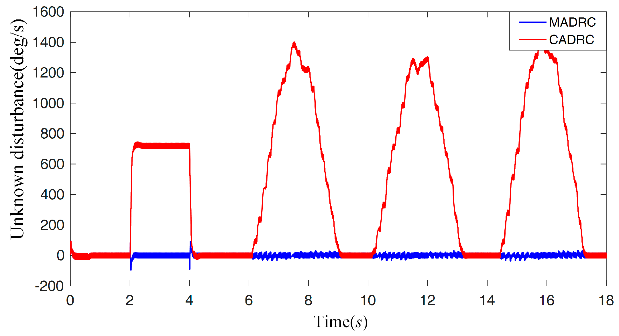
As can be seen in Figure 11. At t = 0 s, the 180 deg step reference is added, the CADRC and MADRC response curves are similar, but the MADRC shows better disturbance rejection performance at the beginning of the second part. In the following part, the negative step disturbance is added, the maximum toolface errors for CADRC and MADRC are 20 deg and 4.5 deg, respectively, and the MADRC reduces 77.5% tracking error of the CADRC. In the last part, sustained oscillations can be observed: the MADRC tracking error is 1.1 deg, but that of the CADRC is 4.9 deg. In Figure 12, the ESO estimated unknown disturbance of CADRC follows the outer housing speed variation, but the one of MADRC is nearly zero, which reveals the MADRC disturbance estimation burden was reduced, and the disturbance rejection performance was improved as desired.
4.1.3. Robustness and Disturbance Rejection Performance Analysis
The DPRSS is operated in harsh drilling conditions, the parameter uncertainties in Equation (16) and the disturbance rejection performance in the presence of various disturbances need to be considered. Since the stabilized platform is sealed inside the outer housing, the total inertia is mainly affected by bit inertia variation, such as the bit balling, which increases the bit inertia, and the bit wear, which decrease the bit inertia. The friction factor is mainly affected by the bearing friction which is related to temperature and bearing load. The motor torque constant is reduced with the increasing of temperature. Considering bit wear [29], bit balling, bear friction variation and motor flux linkage variation [30], the error of , and was assumed to be ±20%, −90% to +100%, and −40% to 0%, respectively. Note that the controller parameters were the same during the simulation.
Considering the parameter uncertainties and load torque disturbance are included in the speed loop, its tracking and disturbance rejection performances in the presence of parameter uncertainties are analyzed.
Since the speed loop MADRC is a linear controller, its frequency response can be obtained by its transfer function. Additionally, since the transient of the current loop is negligible compared with that of the speed loop, for the sake of simplicity, we use instead of in the derivation, and the static friction torque is omitted. The MADRC transfer function is derived based on the CADRC transfer function which was initially presented in [31]. By converting the MADRC algorithm to the frequency domain using the Laplace transform, it is possible to obtain Equation (28) from Equations (15), (19), (20), and (22):
where , , , and are listed in the Appendix A, specifically. If is set to 0, the MADRC is equivalent to the CADRC. The block diagram shown in Figure 13 is derived to obtain the closed–loop transfer function.
where , , and are listed in the Appendix A. Then, the closed–loop transfer function and the disturbance transfer function can be obtained. Note that the load torque disturbance is considered in the form of its motor speed response.
We assumed two extreme conditions to analyse the frequency response in the presence of parameter uncertainties, the first one changed , , and to 20%, 100%, and 0% of their normal values, and the second one reduced the , and to −20%, −90%, and −40% of their normal values. The Bode diagrams of and , along with the two extreme conditions, are shown in Figure 14. For the normal condition without uncertainties, the –3 dB bandwidth of the speed loop is about 520 rad/s, which agrees with . Although the parameter uncertainties affect closed–loop frequency response, the low–frequency tracking responses are almost the same, which guarantees the tracking requirement of the toolface controller output. Figure 14b proves the disturbance rejection ability of the speed control loop since the magnitude responses are under 0 dB within controller baseband, the disturbance frequency responses are almost unchanged with the parameter uncertainties, in addition, with the help of the MC, the MADRC has better disturbance rejection performance, which shows agreement with Figure 7.
Due to the nonlinearity of the function in the toolface loop, it is difficult to analyze the toolface response using frequency domain method. Because the tracking error can show the toolface tracking performance directly, we performed simulations in the presence of various possible parameter uncertainties and disturbances, and the tracking errors are evaluated using the root mean square error (RMSE) index.
Figure 15 shows the toolface tracking RMSEs with parameter uncertainties, the toolface response data shown in Figure 11 was used as the standard value. The toolface RMSE is small and negligible, which reveals that the DPRSS control system is robust in the presence of the possible parameter uncertainties.
Figure 16 shows the toolface tracking RMSEs with various load torque disturbance, the possible load torque magnitude and frequency are varied based on (27), it is observed that the toolface is insensitive to the load torque variation.
For the sake of simplicity, the sinusoidal wave shown in (30) was used to simulate stick-slip, and then, the toolface tracking RMSEs in the presence of outer housing speed disturbance were obtained:
where and denote the amplitude and frequency of the stick-slip, respectively. As can be seen in Figure 17, although the errors increase as the stick-slip becomes more extreme, the controller performs well in rejecting these disturbances.
Although the proposed control method has shown satisfactory performance, there are still a large number of factors, such as model error, sensor error, and measurement delay, which cannot be well considered by simulation, the DPRSS prototype experiments will be performed in the following section.
4.2. DPRSS Prototype Experiment
The DPRSS prototype is shown in Figure 18. The outer housing is connected to the outer housing motor by a spline coupling, and the outer housing motor acts as the upper drilling string which drives the outer housing. The stabilized platform which driven by the PMSM is assembled inside the outer housing. A sensor package, including a gyro, accelerometer, and microprocessor, is installed on the stabilized platform [32]. The proposed controllers are implemented in a TMS320F28335 DSP. The high-speed CAN bus is used for data exchange between the DSP, the microprocessor, and the USB-CAN analyzer. The analyzer acquires all data. The motor speed is measured by a resolver, and the toolface is measured in the way shown in [30].
The outer housing speed disturbance was added by changing the outer housing motor speed, and the load torque disturbance was tested by the equipment shown in Figure 19. The PMSM connects to the torque motor by a spline coupling, the constant load torque is generated by a torque motor and measured by the torque sensor. In the DPRSS prototype experiment, all the controller parameters were the same as the ones used in the simulation.
4.2.1. The Motor Speed Loop Test
Figure 20 shows the motor speed step response curve. The MADRC and CADRC controllers have larger overshoot than the PI algorithm before t = 0.3 s, but their speed fluctuation is much smaller.
Owing to the torque motor limitation, only the constant 0.25 Nm load torque was tested. The load torque disturbance rejection performance is shown in Figure 21. The test results meet an agreement with the simulation in Figure 7, with the load torque being compensated in MADRC, its tracking error is the smallest among the three algorithms. Figure 22 shows the load torque observer output and the torque sensor measurements, the torque estimation error is larger than the one in the simulation, but it follows the real torque tendency as desired.
4.2.2. The Toolface Loop Test
Figure 23 shows the toolface loop response curves of MADRC and CADRC. The outer housing speed disturbances consist of the four parts which have been introduced in Figure 10. Comparing the simulation results shown in Figure 11, the prototype toolface tracking errors are larger, but MADRC still shows better disturbance rejection performance. In the second and third parts, the MADRC maximum error is 10 deg, the CADRC maximum error is 17 deg, which is 70% larger than the MADRC. In the fourth part, the stick-slip disturbance is tested, the CADRC maximum tracking error is 7 deg, and the MADRC maximum tracking error is 4.5 deg, which reduces 36% errors of the CADRC.
Figure 24 shows the real outer housing speed, and the ESO estimated unknown disturbances of the MADRC and CADRC. Due to the model errors, which were not considered in the simulation, the ESO output magnitude in prototype test is larger than the simulation, but the ESO-estimated disturbance of MADRC is still smaller than that of CADRC, thus, the ESO burden is reduced as desired.
In the previous research [12], the best maximum tracking error was 15 deg based on the four–loop PI control method, where the performed stick-slip magnitude was 720 deg/s. By applying the proposed control method, the toolface tracking error was reduced to 4.5 deg with 1400 deg/s stick-slip magnitude. It is clear that the proposed control method has largely improved the DPRSS toolface control precision, and these results show the potential of the proposed method to be used in harsher drilling conditions.
5. Conclusions
In this paper, a DPRSS toolface control method using the MADRC algorithm was proposed and verified, to our knowledge, it is the first time that the MADRC has been used for DPRSS. The frequency responses and the simulation results reveal that the proposed method is robust against parameter uncertainties: the RMSEs in the presence of various external disturbances are less than 1 deg. The experimental results also indicate that the toolface control system satisfies the field requirements; its maximum tracking errors are less than 10 deg under the four typical drilling conditions. Furthermore, the MADRC shows better disturbance rejection performance than the CADRC and PI algorithms. This work demonstrated that the MADRC has the potential to guarantee the DPRSS steering performance in harsher drilling conditions. Stabilized platform toolface control performance testing in actual drilling processes are considered for future work.
Author Contributions
Conceptualization, W.W. and Y.G.; Methodology, W.W.; Software, N.W. and X.P.; Validation, W.W. and N.W.; Formal Analysis, W.W. and Y.G.; Investigation, N.W. and X.P.; Resources, Y.G.; Data Curation, Y.G.; Writing-Original Draft Preparation, W.W.; Writing-Review & Editing, Y.G. and J.d.O.F.; Visualization, W.W.; Supervision, Y.G.; Project Administration, Y.G.; Funding Acquisition, Y.G.
Funding
This research was funded by [Ministry of Science and Technology of the People’s Republic of China] grant number [2016YFC0302800] and [Ministry of Education of the People’s Republic of China] grant number [15CX06065A] and [15CX08014A].
Conflicts of Interest
The authors declare no conflict of interest.
Appendix A
References
- Schaaf, S.; Mallary, C.; Pafitis, D. Point-the-bit rotary steerable system: Theory and field results. In Proceedings of the SPE Annual Technical Conference and Exhibition, Dallas, TX, USA, 1–4 October 2000; Society of Petroleum Engineers: Houston, TX, USA, 2000. [Google Scholar]
- Zhang, C.; Zou, W.; Cheng, N. Overview of rotary steerable system and its control methods. In Proceedings of the 2016 IEEE International Conference on Mechatronics and Automation (ICMA), Harbin, China, 7–10 August 2016; IEEE: Piscataway, NJ, USA, 2016; pp. 1559–1565. [Google Scholar]
- Vadali, M.; Xue, Y.; Song, X.; Dykstra, J. Control of Rotary Steerable Toolface in Directional Drilling. In Proceedings of the ASME 2015 Dynamic Systems and Control Conference, Columbus, OH, USA, 28–30 October 2015; American Society of Mechanical Engineers: New York, NY, USA, 2015. [Google Scholar]
- Wang, W.; Geng, Y.; Yan, Z. Dynamic Point-the-Bit Rotary Steerable Drilling Tool and Measuring Method Thereof. U.S. Patent US9587440B2, 7 March 2017. [Google Scholar]
- Zhang, Y.; Yi, J. Adaptive Second Sliding Mode Control for Stabilized Platform of Rotary Steering Drilling Tool. In Proceedings of the 2013 International Conference on Mechanical and Automation Engineering (MAEE), Jiujang, China, 21–23 July 2013; IEEE: Piscataway, NJ, USA, 2013; pp. 140–143. [Google Scholar]
- Li, Y.; Cheng, W.; Tang, N.; Huo, A.; Wang, Y.; Guo, Y.; Kang, S. The intelligent PID control of the rotary navigational drilling tool. China Pet. Mach. 2010, 38, 13–16. [Google Scholar]
- Feng, S.; Guanyun, L.; Qingming, M. A strap-down automatic vertical drilling system. Acta Pet. Sin. 2011, 32, 360–363. [Google Scholar]
- Kim, J.; Myung, H. Development of a Novel Hybrid-Type Rotary Steerable System for Directional Drilling. IEEE Access 2017, 5, 24678–24687. [Google Scholar] [CrossRef]
- Kremers, N.A.H.; Detournay, E.; van de Wouw, N. Model-based robust control of directional drilling systems. IEEE Trans. Control Syst. Technol. 2016, 24, 226–239. [Google Scholar] [CrossRef]
- Tang, N.; Huo, A.; Wang, Y.; Cheng, W. Experimental study on control function of stabilized platform for rotary steering drilling tool. Acta Pet. Sin. 2008, 29, 284. [Google Scholar]
- Wang, Y.; Wang, H.; Kang, S. Output feedback linearization of servo platform for rotary steering drilling system. Acta Pet. Sin. 2014, 35, 952–957. [Google Scholar]
- Wang, K.; Wang, W.; Si, J.; Li, C.; Geng, Y.F. Research on the Measurement and Control System of Dynamic Point-the-bit Rotary Steerable Drilling Tools. China Pet. Mach. 2018, 46, 35–38, 67. [Google Scholar]
- Yong, D.Z.; Yong, P. A Comparative Analysis to Traditional PID and Fuzzy Adaptive PI-Variable Damping Controlling System of MRST Stabilized Platform. In Proceedings of the 2009 International Conference on Measuring Technology and Mechatronics Automation, Zhangjiajie, China, 11–12 April 2009; IEEE: Piscataway, NJ, USA, 2009; pp. 745–748. [Google Scholar]
- Huo, A.; He, Y.; Wang, Y.; Tang, N.; Cheng, W. Research of disc valve friction torque modeling and integral sliding mode adaptive control for rotary steering drilling tool. In Proceedings of the 2010 2nd International Conference on Computer Engineering and Technology (ICCET), Chengdu, China, 16–18 April 2010; IEEE: Piscataway, NJ, USA, 2010; pp. V1-715–V1-719. [Google Scholar]
- Han, J. From PID to active disturbance rejection control. IEEE Trans. Ind. Electron. 2009, 56, 900–906. [Google Scholar] [CrossRef]
- Du, L.; Zhang, K.; Jin, G. Linear auto disturbance rejection controller for vector-controlled PMSM drive system. In Proceedings of the 2011 International Conference on Transportation, Mechanical, and Electrical Engineering (TMEE), Changchun, China, 16–18 December 2011; IEEE: Piscataway, NJ, USA, 2011; pp. 879–882. [Google Scholar]
- Tong, Z.; Hong, G.; Jinquan, X.; Xiaolin, K.; Hao, Q. Research on PMSM active disturbance rejection controller based on model compensation. In Proceedings of the 2015 18th International Conference on Electrical Machines and Systems (ICEMS), Pattaya, Thailand, 25–28 October 2015; IEEE: Piscataway, NJ, USA, 2015; pp. 1593–1596. [Google Scholar]
- Wang, L.; Zhang, H.; Liu, X. Robust sensorless of ADRC controlled PMSM based on MRAS with stator resistance identification. In Proceedings of the 2011 30th Chinese Control Conference (CCC), Yantai, China, 22–24 July 2011; IEEE: Piscataway, NJ, USA, 2011; pp. 3575–3579. [Google Scholar]
- Pillay, P.; Krishnan, R. Control characteristics and speed controller design for a high performance permanent magnet synchronous motor drive. IEEE Trans. Power Electron. 1990, 5, 151–159. [Google Scholar] [CrossRef]
- Chen, S.; Bai, W.; Huang, Y. ADRC for systems with unobservable and unmatched uncertainty. In Proceedings of the 2016 35th Chinese Control Conference (CCC), Chengdu, China, 27–29 July 2016; IEEE: Piscataway, NJ, USA, 2016; pp. 337–342. [Google Scholar]
- Guo, B.; Bacha, S.; Alamir, M. A review on ADRC based PMSM control designs. In Proceedings of the IECON 2017—43rd Annual Conference of the Industrial Electronics Society, Beijing, China, 29 October–1 November 2017; IEEE: Piscataway, NJ, USA, 2017; pp. 1747–1753. [Google Scholar]
- Gao, Z. Scaling and bandwidth-parameterization based controller tuning. In Proceedings of the American Control Conference, Denver, CO, USA, 4–6 June 2006; pp. 4989–4996. [Google Scholar]
- Zhao, Z.-L.; Guo, B.-Z. A nonlinear extended state observer based on fractional power functions. Automatica 2017, 81, 286–296. [Google Scholar] [CrossRef]
- Li, J.; Xia, Y.; Qi, X.; Gao, Z. On the necessity, scheme, and basis of the linear–nonlinear switching in active disturbance rejection control. IEEE Trans. Ind. Electron. 2017, 64, 1425–1435. [Google Scholar] [CrossRef]
- Zhao, Z.-L.; Guo, B.-Z. A novel extended state observer for output tracking of MIMO systems with mismatched uncertainty. IEEE Trans. Autom. Control 2018, 63, 211–218. [Google Scholar] [CrossRef]
- Pavone, D.; Desplans, J. Application of high sampling rate downhole measurements for analysis and cure of stick-slip in drilling. In Proceedings of the SPE Annual Technical Conference and Exhibition, New Orleans, LA, USA, 25–28 September 1994; Society of Petroleum Engineers: Houston, TX, USA, 1994. [Google Scholar]
- Barton, S. Development of stable PDC bits for specific use on rotary steerable systems. In Proceedings of the IADC/SPE Asia Pacific Drilling Technology, Kuala Lumpur, Malaysia, 11–13 September 2000; Society of Petroleum Engineers: Houston, TX, USA, 2000. [Google Scholar]
- Chen, S.; Blackwood, K.; Lamine, E. Field investigation of the effects of stick-slip, lateral, and whirl vibrations on roller cone bit performance. In Proceedings of the SPE Annual Technical Conference and Exhibition, Houston, TX, USA, 3–6 October 1999; Society of Petroleum Engineers: Houston, TX, USA, 1999. [Google Scholar]
- Ersoy, A.; Waller, M. Wear characteristics of PDC pin and hybrid core bits in rock drilling. Wear 1995, 188, 150–165. [Google Scholar] [CrossRef]
- Sun, Z. Research on Performance and Temperature Rise of Permanant Magnet Synchronous Motor in High Temperature Environment; Harbin Institute of Technology: Harbin, China, 2017. [Google Scholar]
- Tian, G.; Gao, Z. Frequency response analysis of active disturbance rejection based control system. In Proceedings of the 2007 IEEE International Conference on Control Applications, Singapore, 1–3 October 2007; IEEE: Piscataway, NJ, USA, 2007; pp. 1595–1599. [Google Scholar]
- Wang, W.; Geng, Y.; Wang, K.; Si, J.; Fiaux, J. Dynamic Toolface Estimation for Rotary Steerable Drilling System. Sensors 2018, 18, 2944. [Google Scholar] [CrossRef]
Figure 1.
Schematic of the directional drilling system.

Figure 2.
Structure of the RSS toolface control method.

Figure 3.
Structural schematic of the DPRSS.

Figure 4.
Block diagram of the MADRC.

Figure 5.
The scheme of the toolface control method.

Figure 6.
Simulation diagram of the toolface control method.

Figure 7.
CADRC, MADRC, and PI response curves.

Figure 8.
The ESO estimated unknown disturbance of CADRC and MADRC in the speed loop.

Figure 9.
The load torque variation and load torque observer output.

Figure 10.
The outer housing speed disturbance.

Figure 11.
The toolface response curves.

Figure 12.
The ESO estimated disturbances of CADRC and MADRC in the toolface loop.

Figure 13.
Block diagram of the speed–loop MADRC in the frequency domain.

Figure 14.
Frequency response of the speed–loop. (a) the frequency response of ; and (b) the frequency response of with parameter uncertainties.
Figure 14.
Frequency response of the speed–loop. (a) the frequency response of ; and (b) the frequency response of with parameter uncertainties.

Figure 15.
The toolface RMSE in the presence of parameter uncertainties.

Figure 16.
Toolface tracking errors in the presence of load torque.

Figure 17.
Toolface tracking errors in the presence of stick-slip.

Figure 18.
DPRSS Prototype.

Figure 19.
Load torque test equipment.

Figure 20.
Speed loop step response curves.

Figure 21.
Load torque rejection curve of the motor speed loop.

Figure 22.
Comparison of the load torque observer and the torque sensor.

Figure 23.
Toolface response curves.

Figure 24.
The ESO outputs of MADRC, CADRC, and the outer housing speed.


Table 1.
Specification of the PMSM.
| Rated Power | 452 W | Rated Voltage | 48 V |
| Rated Current | 4.7 A | Pole Pairs | 4 |
| Stator Inductance | 0.0021383 H | Stator Resistance | 1.52 Ohm |
| Rated Speed | 2280 RPM | Total Inertia | 1.4490 × 10⁻⁵ kgm2 |
| Rated Torque | 0.69 Nm | Torque Constant | 0.12887 Nm/Apeak |
| Static Friction | 0.0115 Nm | Viscous Coefficient | 0.00008 Nms |
Table 2.
Controller parameters.
| 555 | 40 | ||
| 555 | 65 | ||
| 509,831 | 1 |
© 2019 by the authors. Licensee MDPI, Basel, Switzerland. This article is an open access article distributed under the terms and conditions of the Creative Commons Attribution (CC BY) license (http://creativecommons.org/licenses/by/4.0/).
Share and Cite
MDPI and ACS Style
Wang, W.; Geng, Y.; Wang, N.; Pu, X.; Fiaux, J.d.O. Toolface Control Method for a Dynamic Point-the-Bit Rotary Steerable Drilling System. Energies 2019, 12, 1831. https://doi.org/10.3390/en12101831
AMA Style
Wang W, Geng Y, Wang N, Pu X, Fiaux JdO. Toolface Control Method for a Dynamic Point-the-Bit Rotary Steerable Drilling System. Energies. 2019; 12(10):1831. https://doi.org/10.3390/en12101831
Chicago/Turabian StyleWang, Weiliang, Yanfeng Geng, Ning Wang, Xiaojiao Pu, and Joice de Oliveira Fiaux. 2019. "Toolface Control Method for a Dynamic Point-the-Bit Rotary Steerable Drilling System" Energies 12, no. 10: 1831. https://doi.org/10.3390/en12101831
Note that from the first issue of 2016, this journal uses article numbers instead of page numbers. See further details here.