Photovoltaic Integrated Hybrid Microgrid Structured Electric Vehicle Charging Station and Its Energy Management Approach

 , ,
, ,  ,
,
Abstract
:1. Introduction
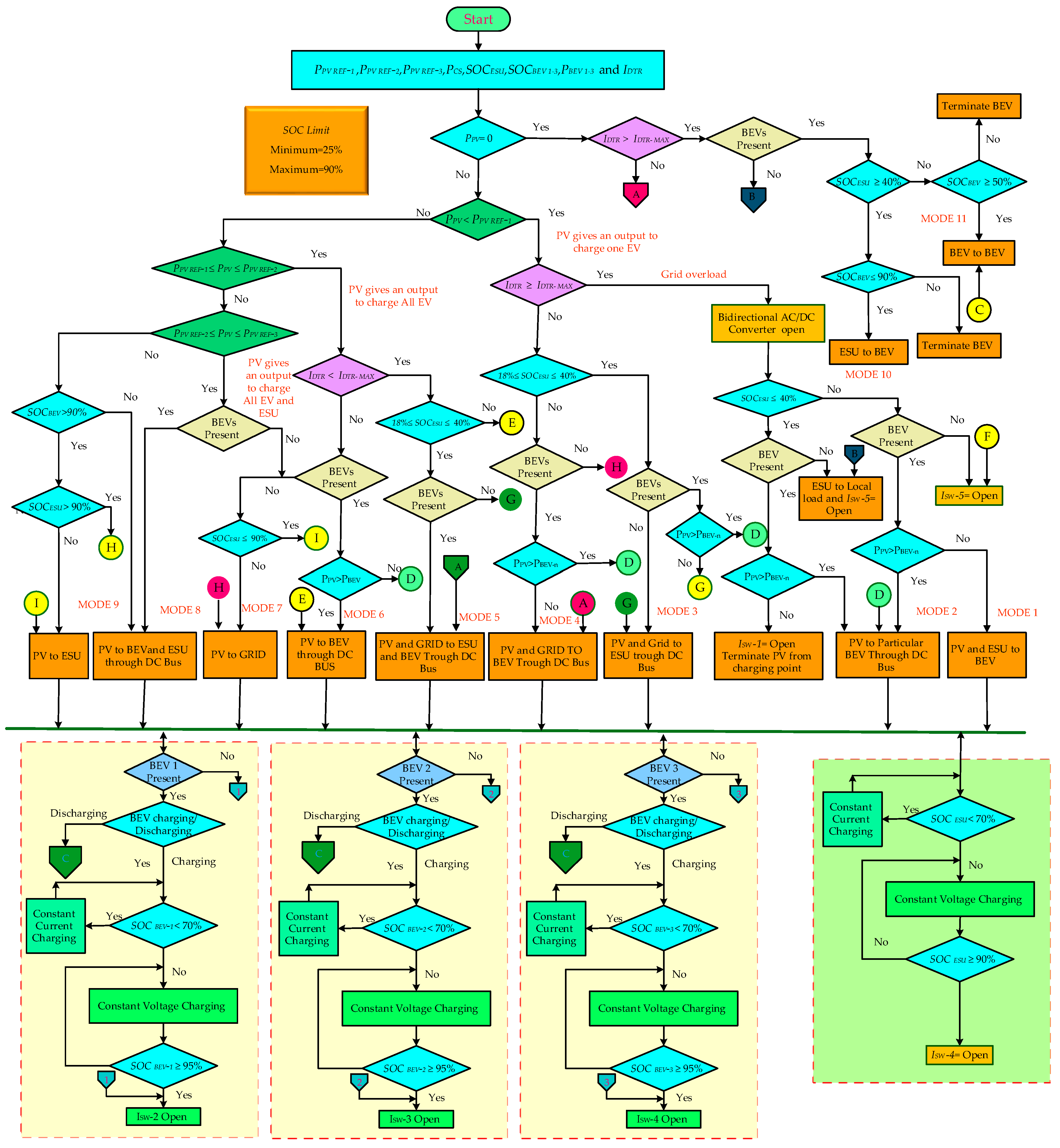
- Eleven different modes of energy management strategies are developed for the proposed microgrid to provide continuous power to the BEV charging point.
- When the utility grid is fully loaded and irradiation for PV energy production is low, BEV charging is delayed or temporarily interrupted, and the ESU and vehicle-to-vehicle charging manage the power demand.
- Mathematical power balance equations for all 11 modes are used to analyze the power flow.
- The proposed hybrid multiport charging station with an EMS was developed and simulated through MATLAB/Simulink. Also, an experimental study was carried out for different modes of operation.
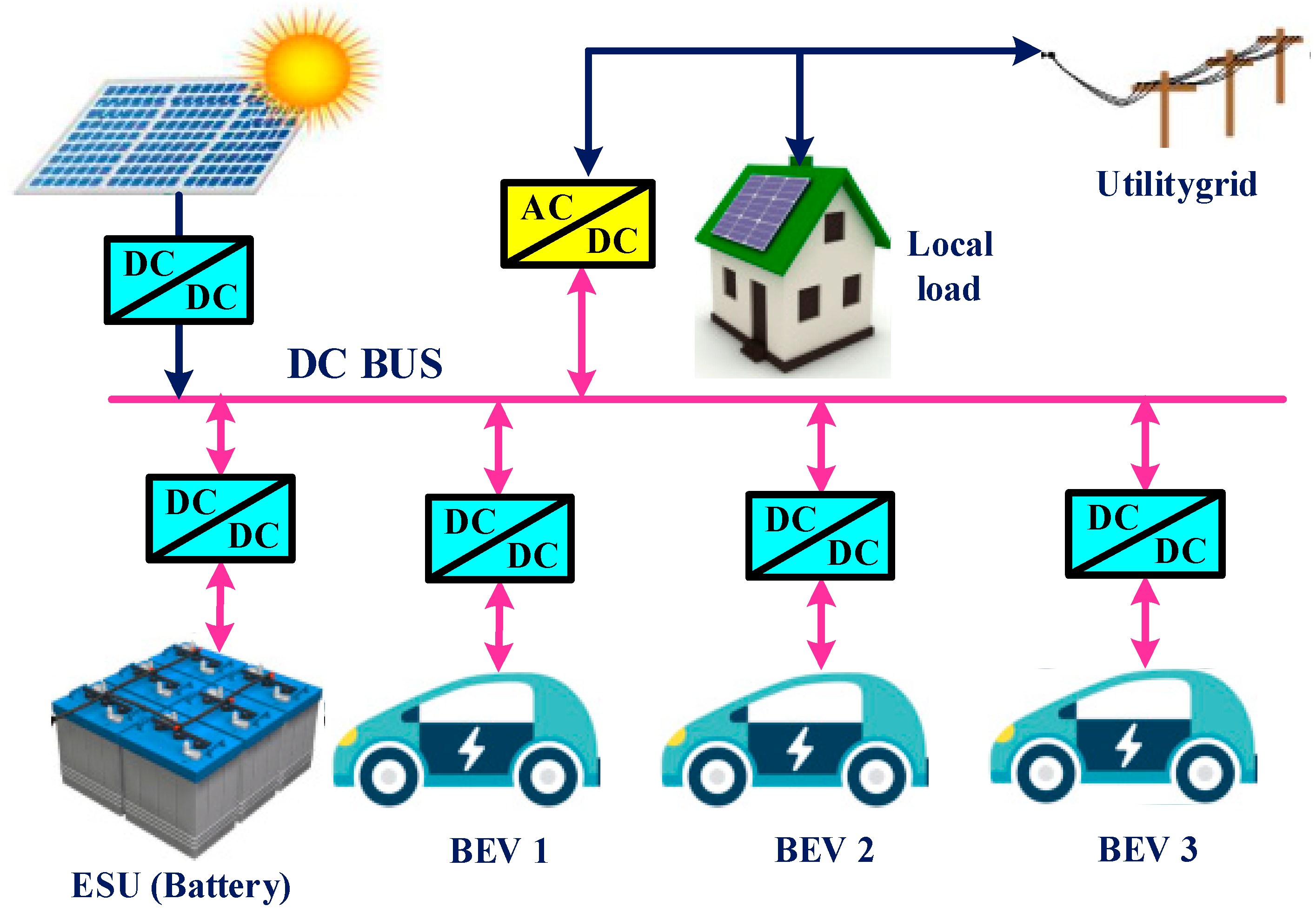
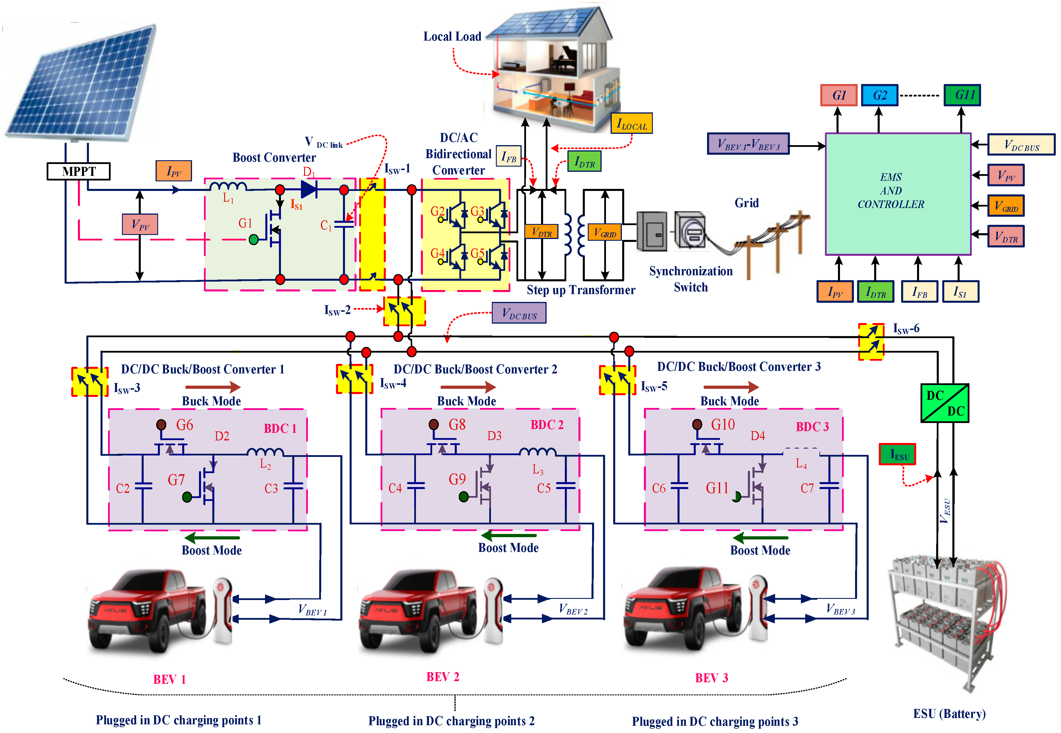
2. Proposed Utility Grid-Integrated Charging Station
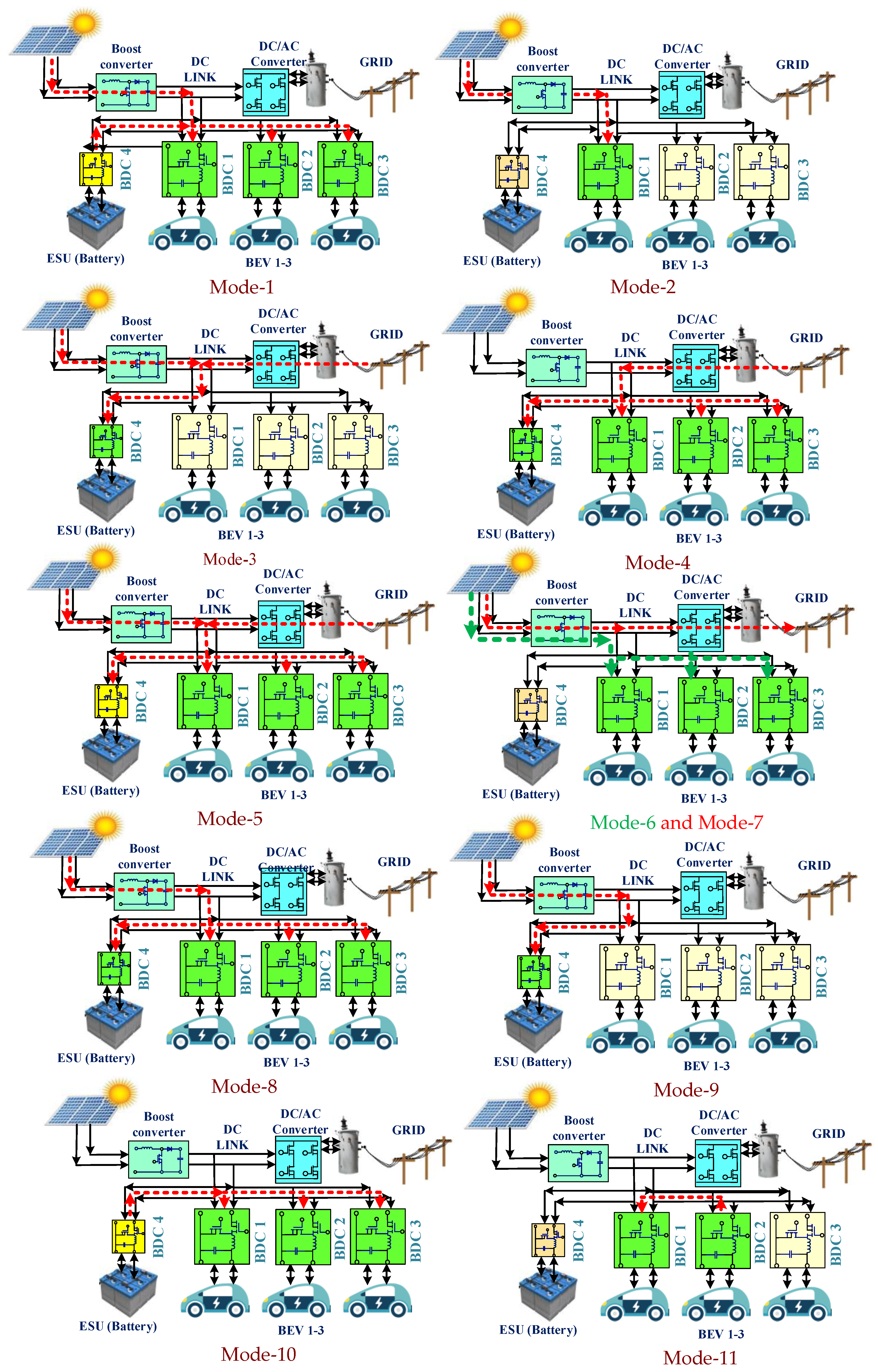
3. Energy Management Modes of Charging Station
- (1)
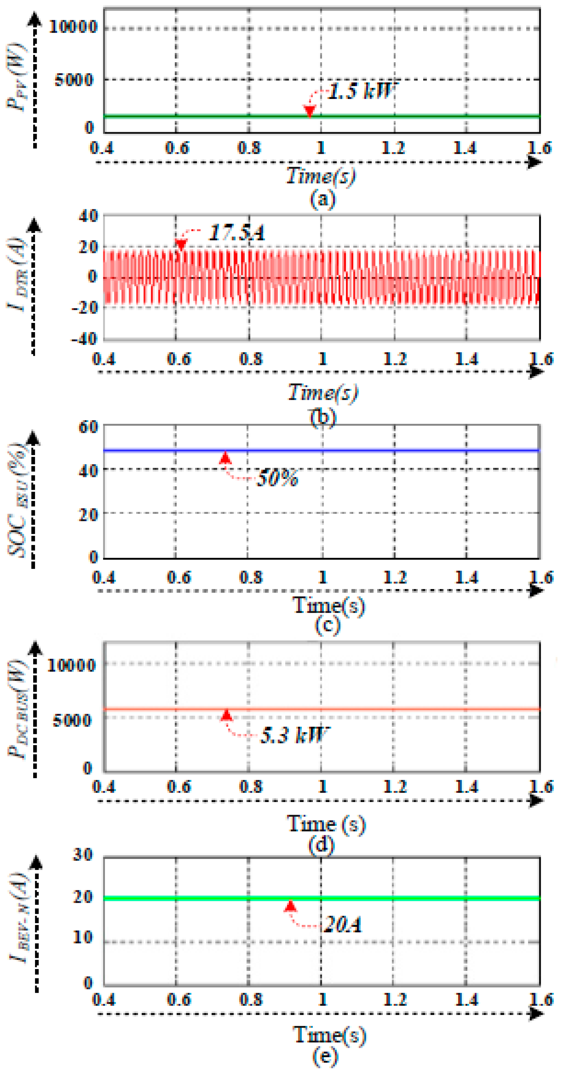
- PV and ESU to BEV charging mode (Mode-1).
- (2)
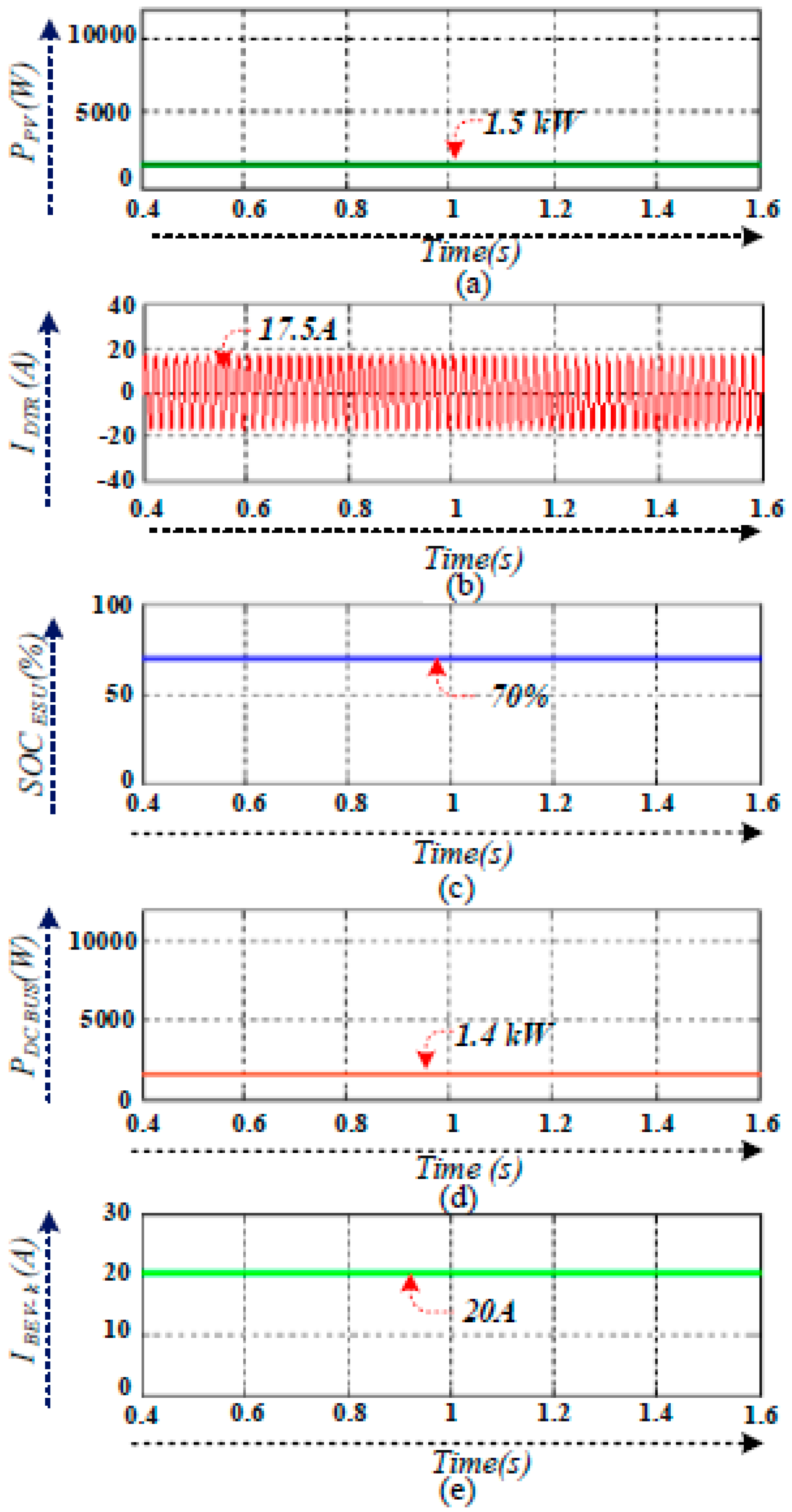
- PV to particular BEV charging mode (Mode-2).
- (3)
- PV and utility grid-connected ESU charging mode (Mode-3).
- (4)
- PV and utility grid-connected BEV charging mode (Mode-4).
- (5)
- PV and utility grid-connected ESU and BEV charging mode (Mode-5).
- (6)
- PV to BEV charging mode (Mode-6).
- (7)
- PV to grid inversion mode (Mode-7).
- (8)
- PV to ESU and BEV charging mode (Mode-8).
- (9)
- PV to ESU charging mode (Mode-9).
- (10)
- ESU to BEV charging mode (Mode-10).
- (11)
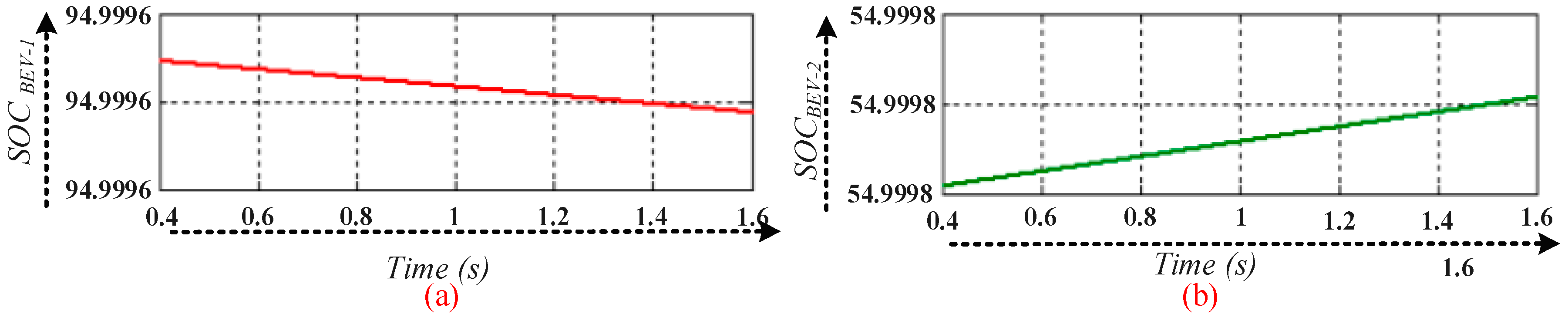
- BEV to BEV charging mode (Mode-11).
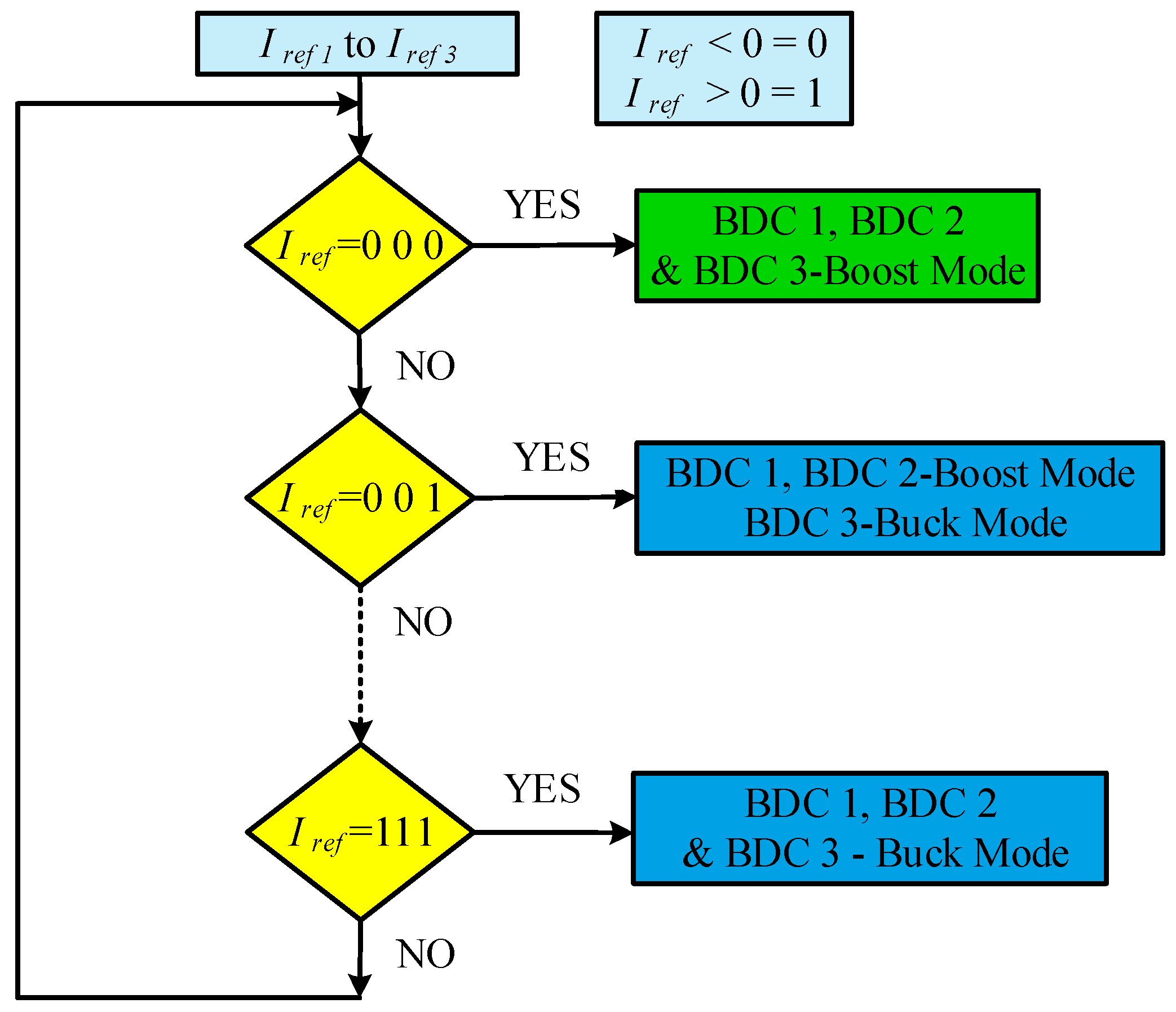
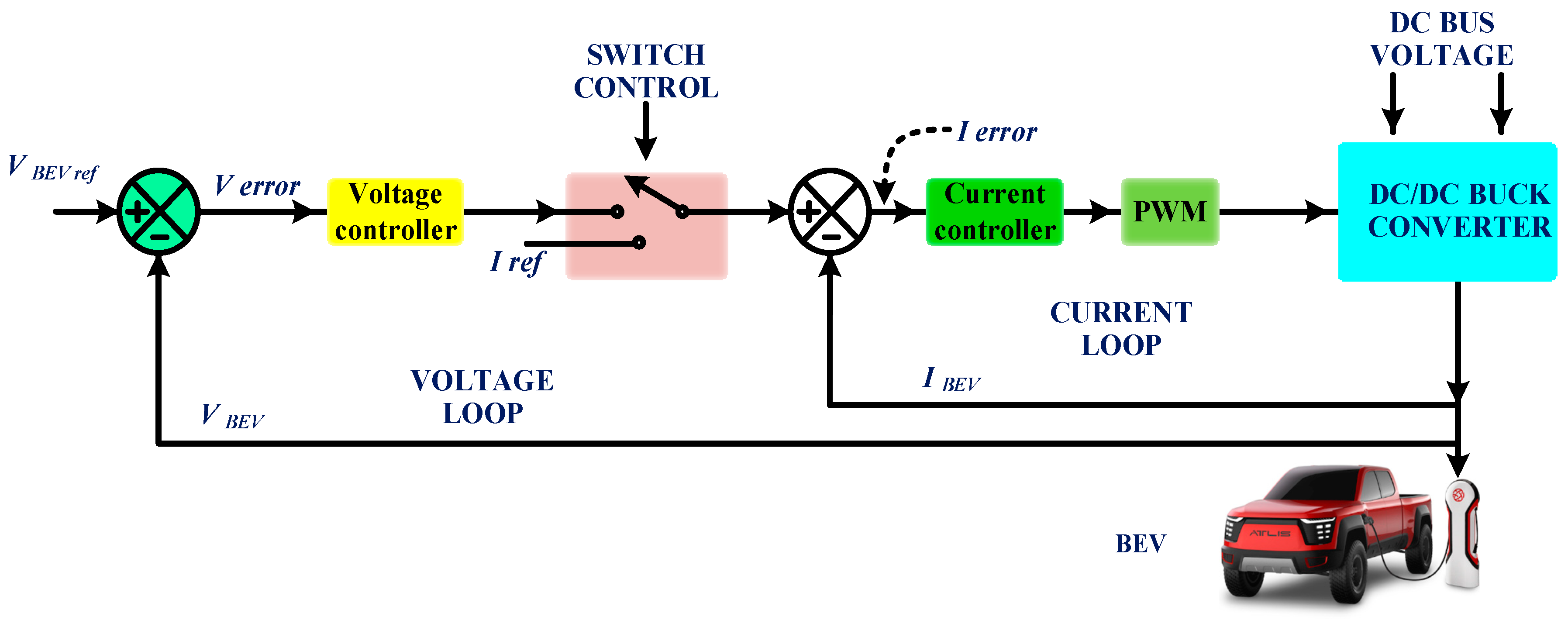
4. Control Operation of Power Converters
BEV Battery Charging Controller
5. Simulation and Evaluation of Charging Station
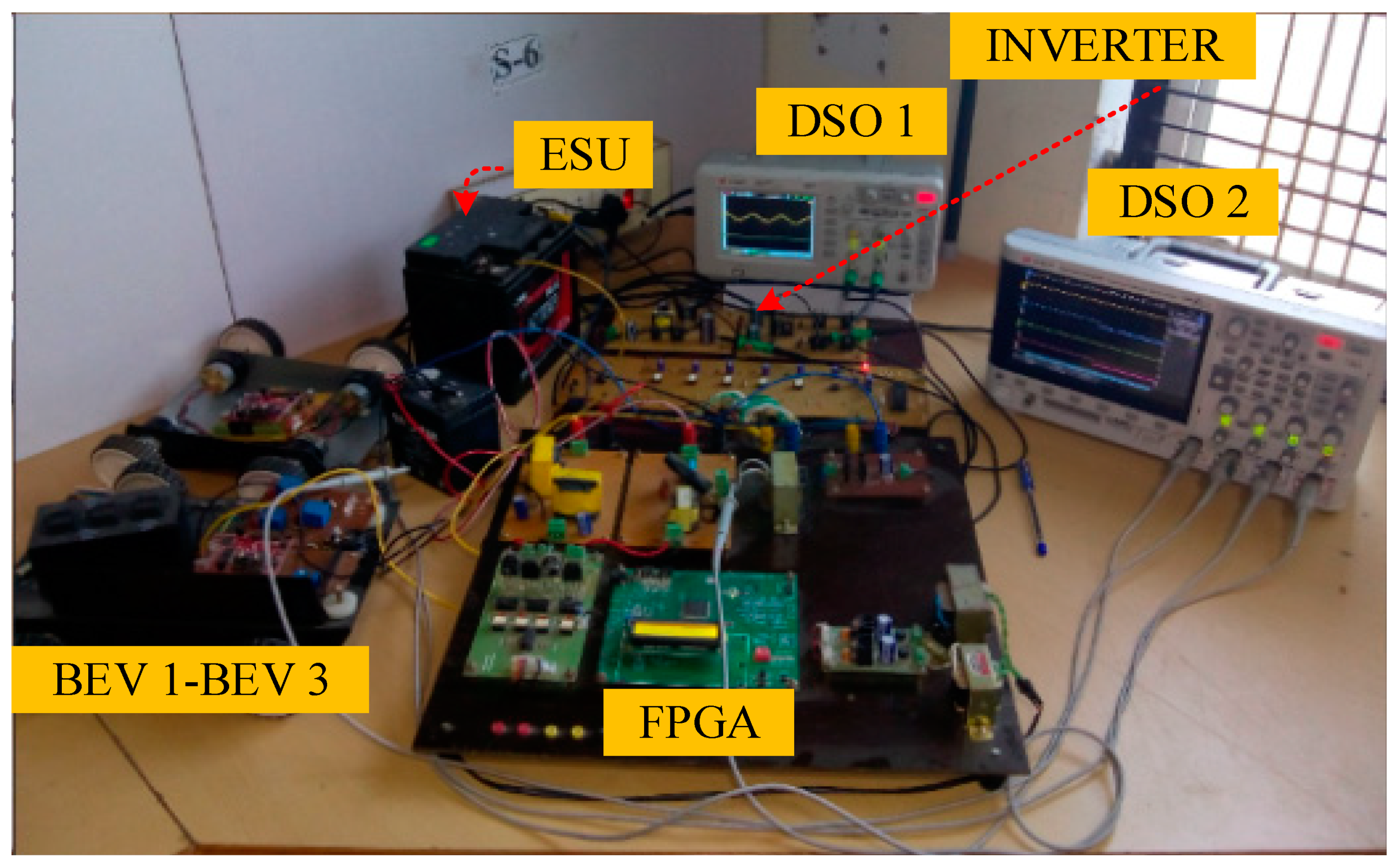
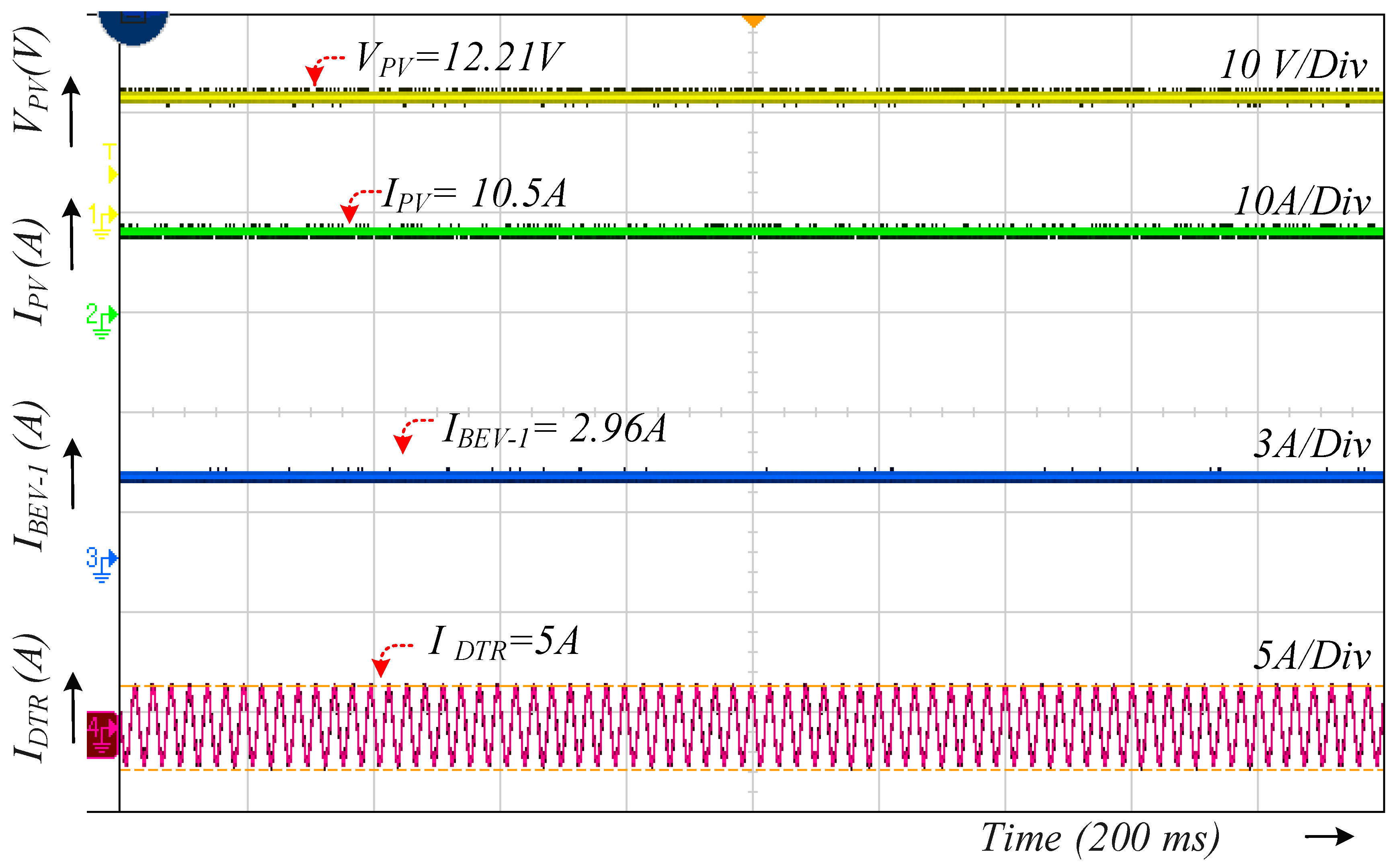
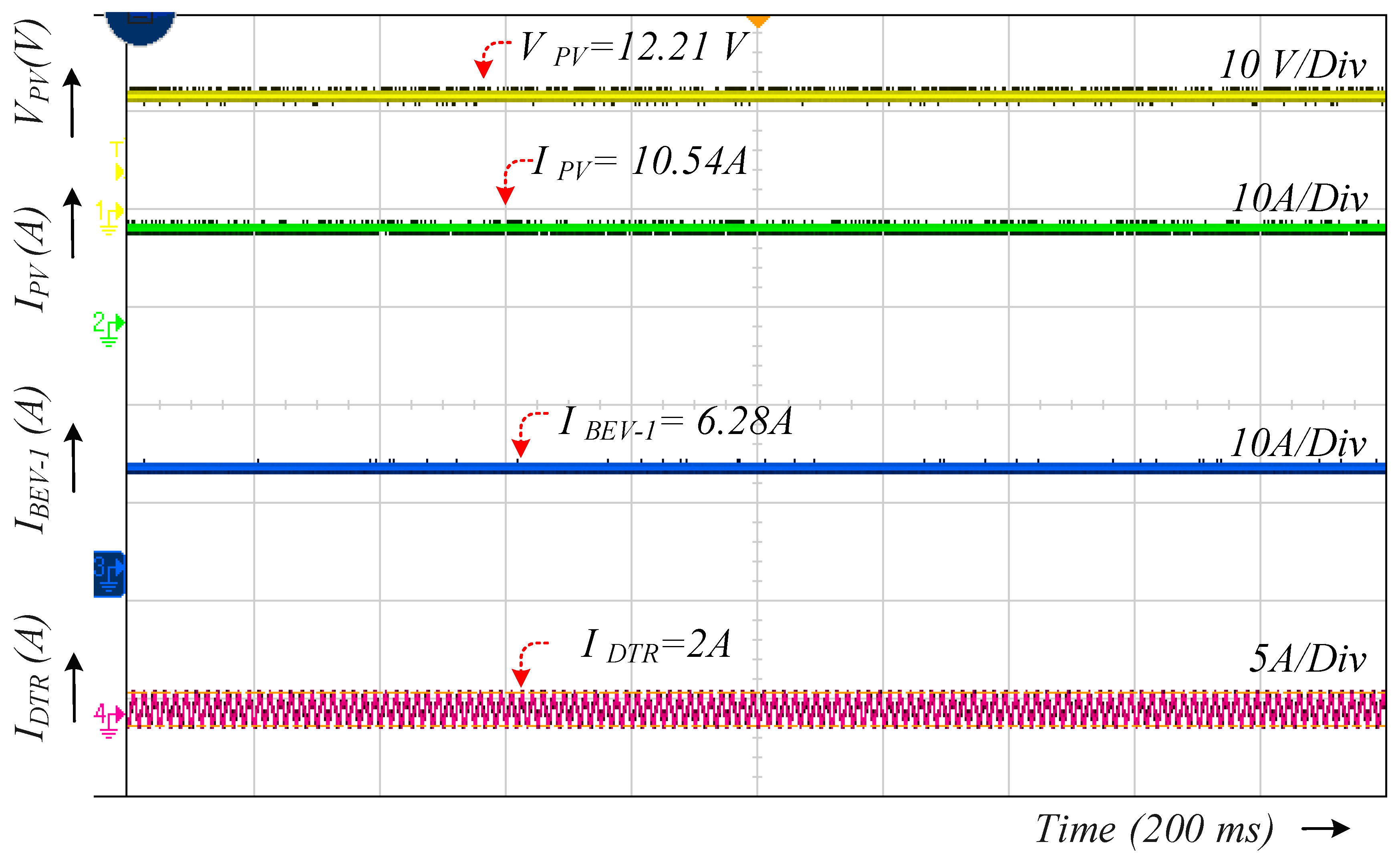
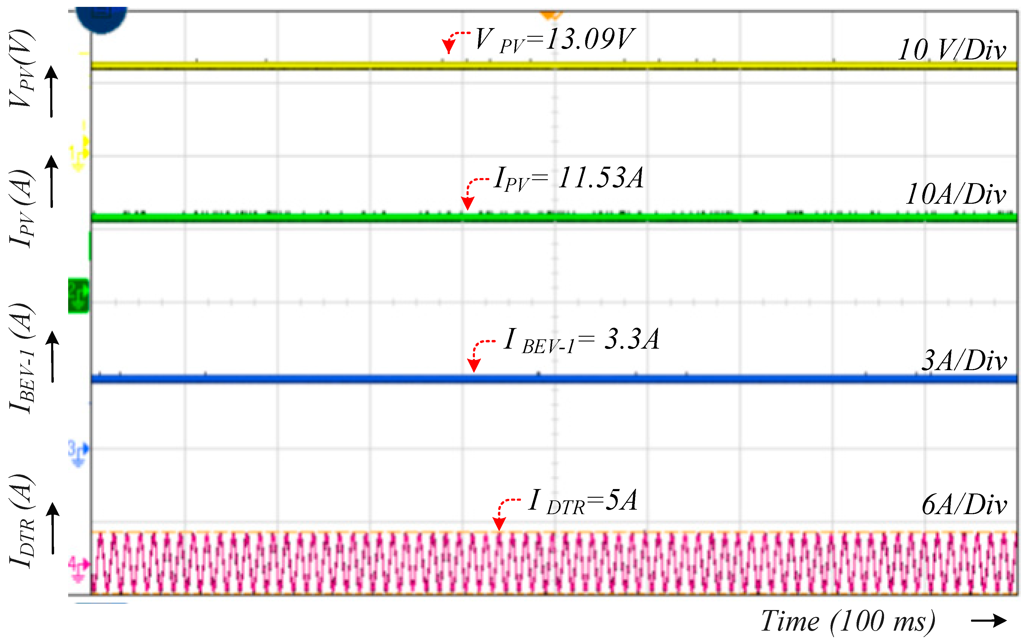
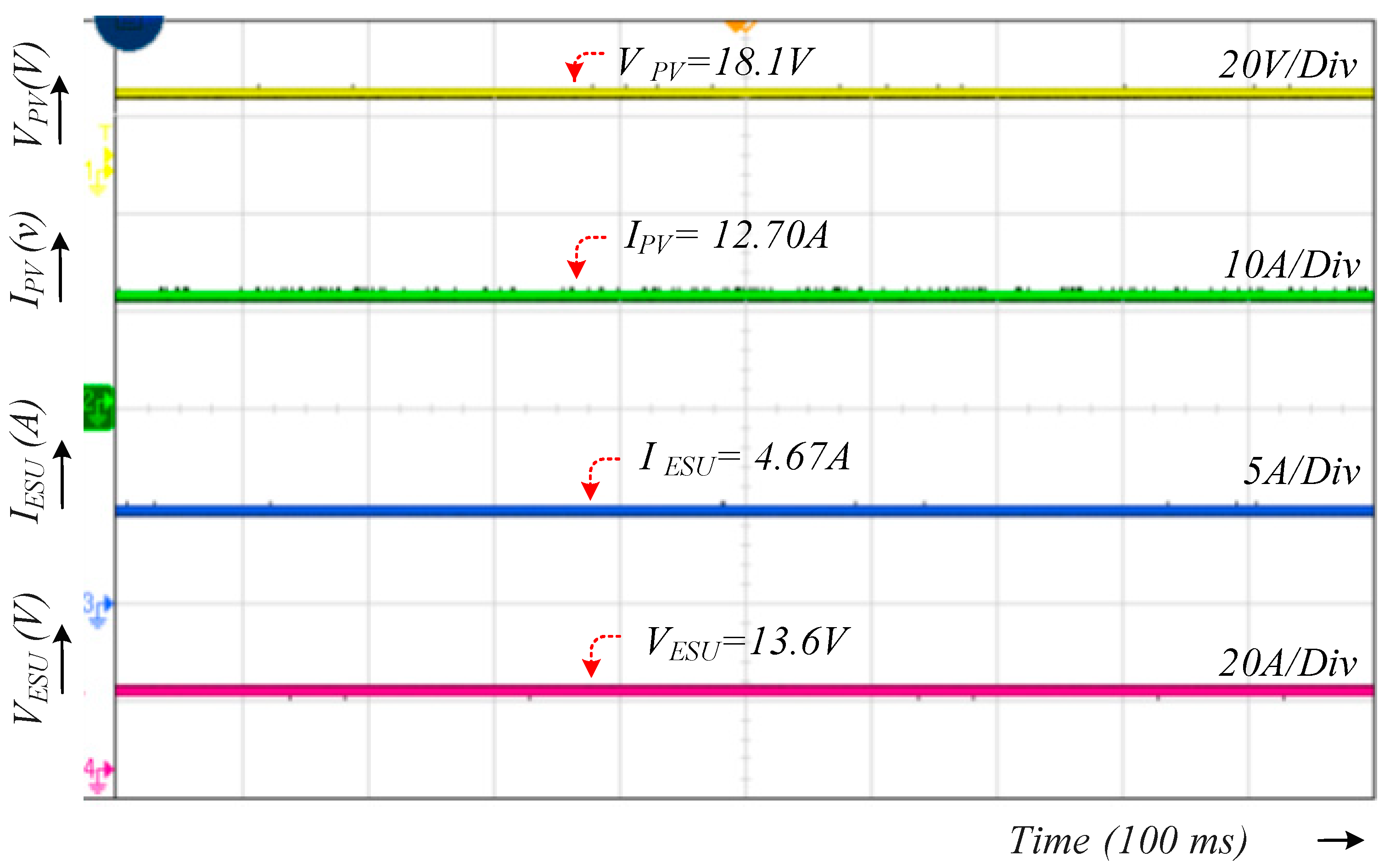
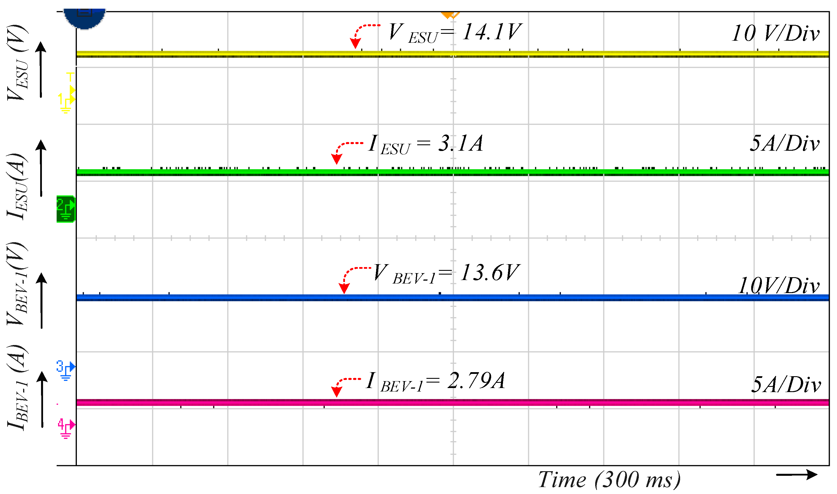
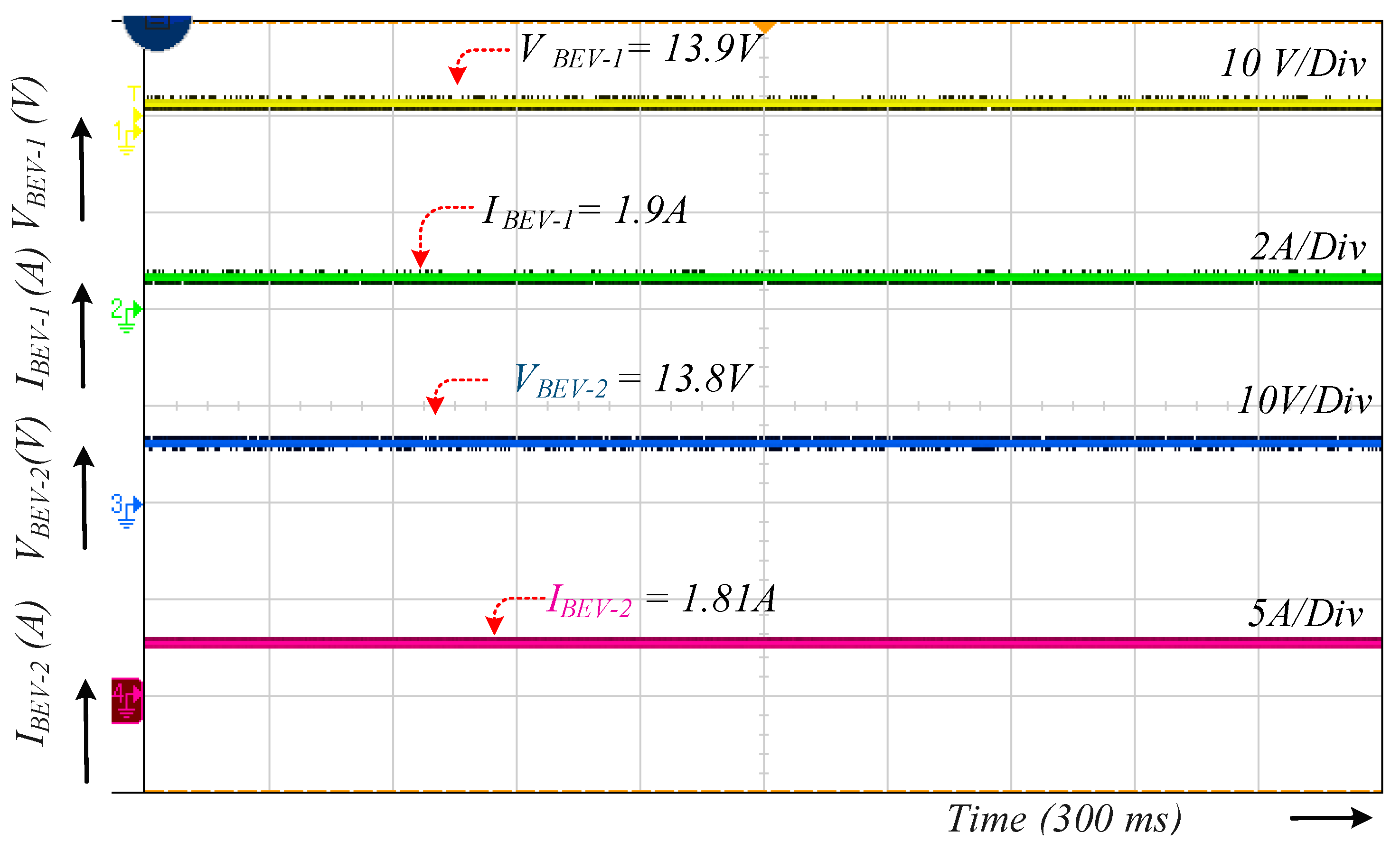
6. Experimental Validation
- (1)
- PV and ESU to BEV charging mode (PPV ≤ 120 W).
- (2)
- PV to particular BEV charging mode (PPV ≤ 120 W).
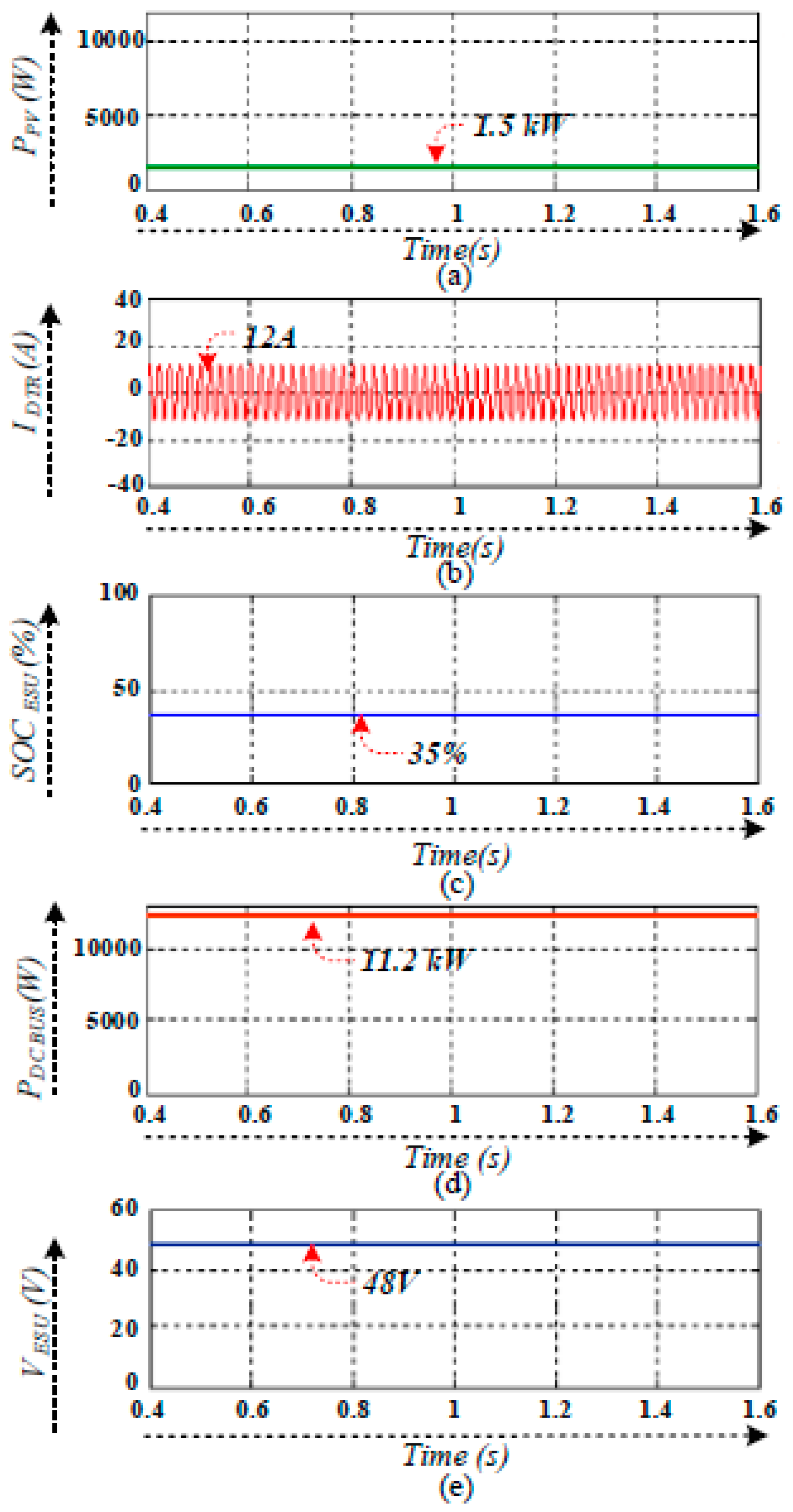
- (3)
- PV and utility grid-connected ESU charging mode (PPV ≤ 120 W).
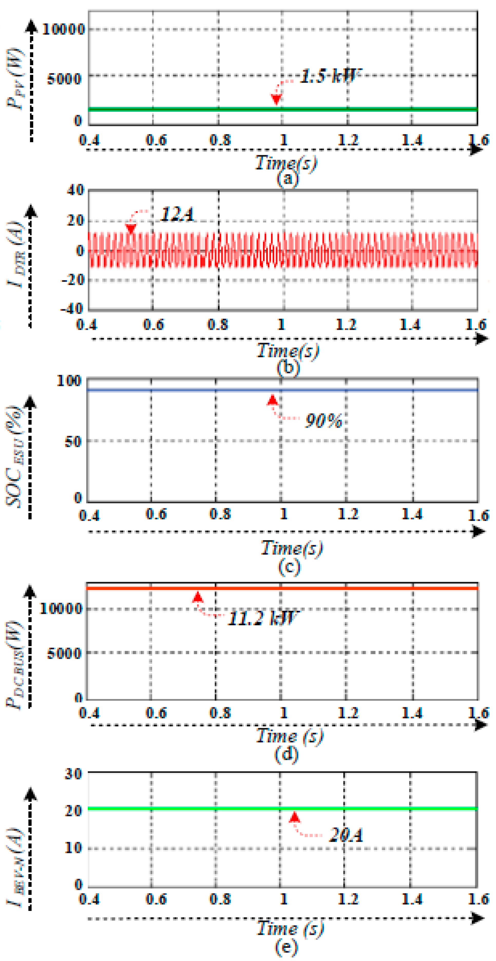
- (4)
- PV and utility grid-connected ESU and BEV charging mode (PPV ≤ 120 W).
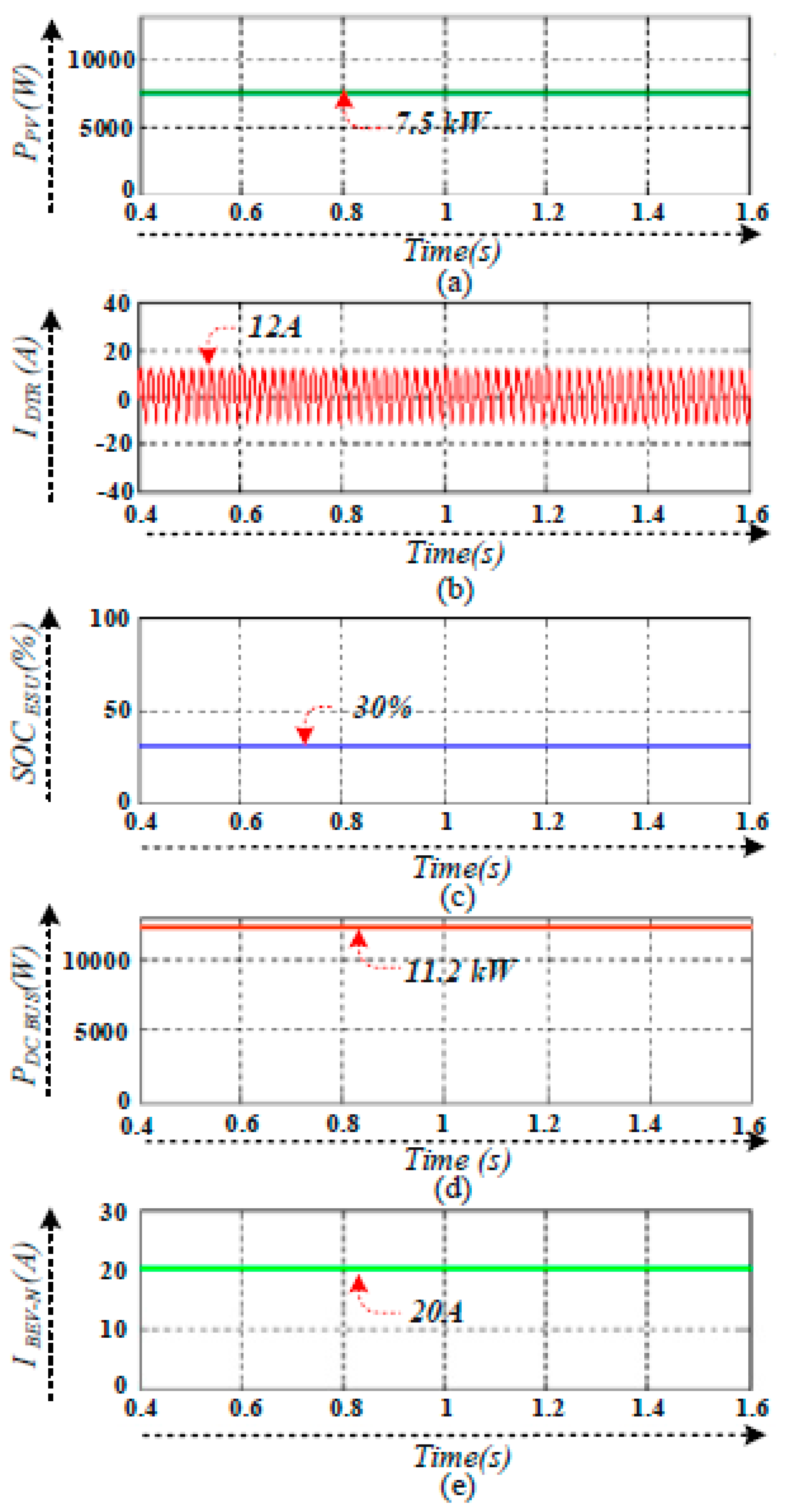
- (5)
- PV and utility grid-connected BEV charging mode (120 W ≤ PPV ≤ 160 W).
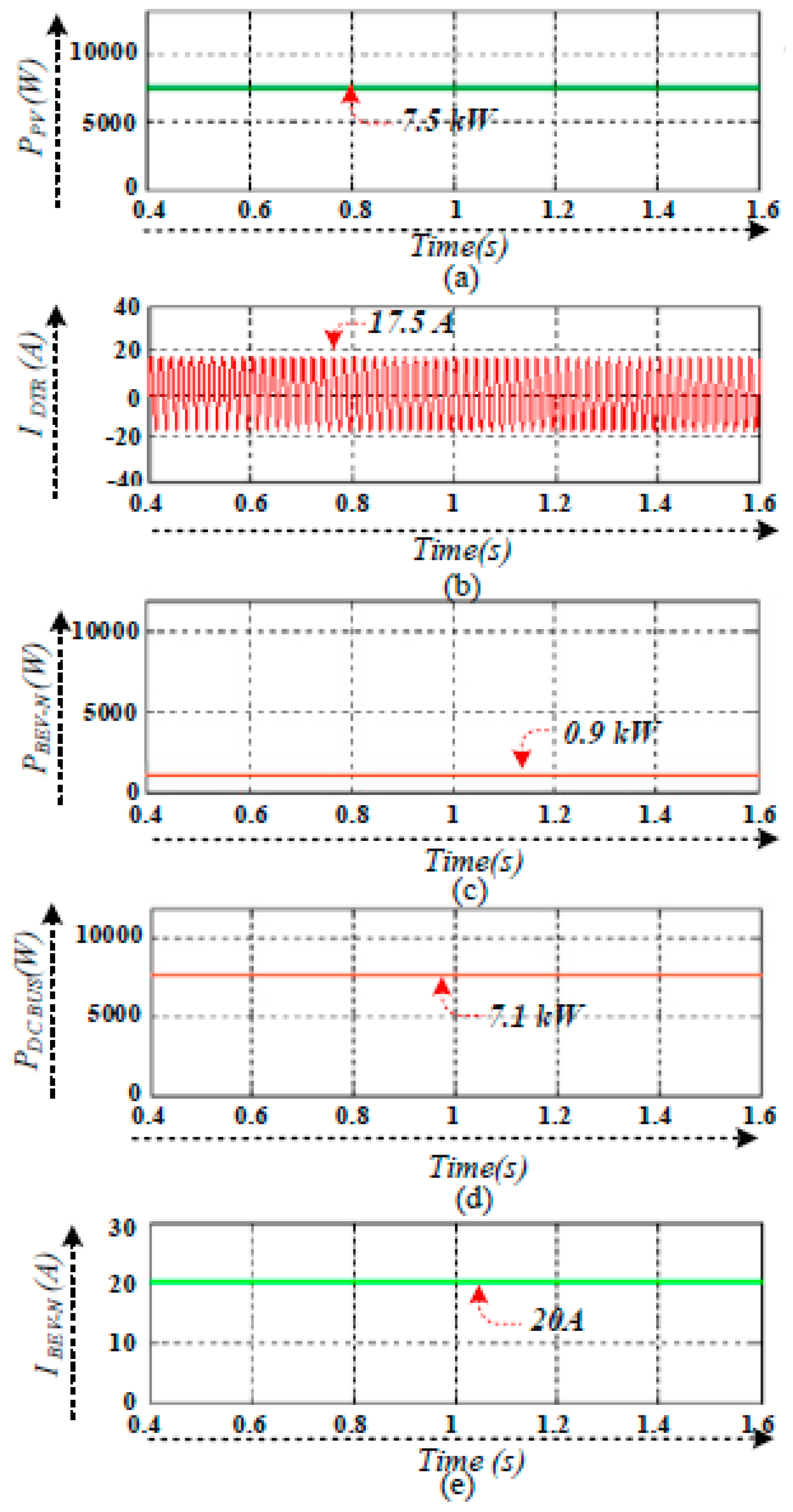
- (6)
- PV to BEV charging mode (120 W ≤ PPV ≤ 160 W).
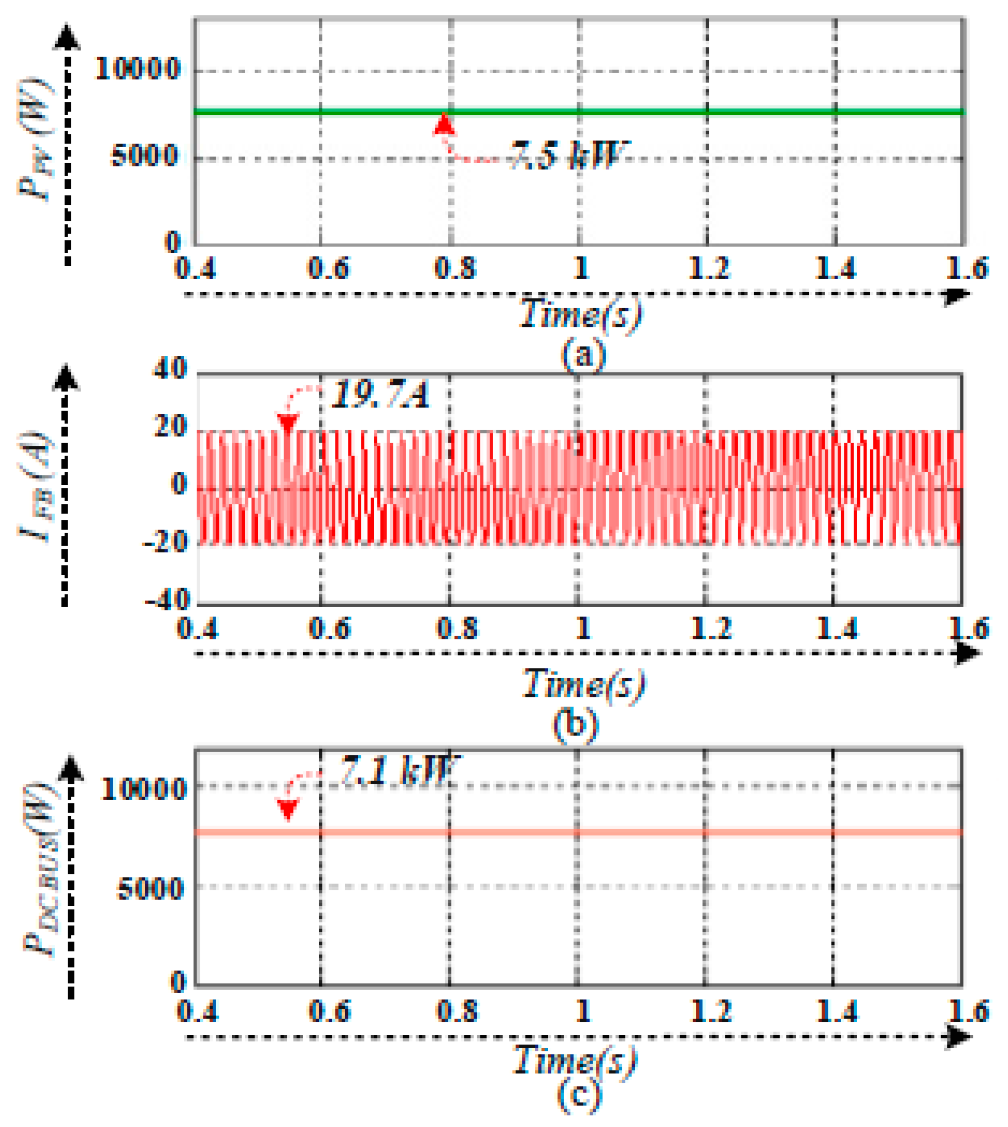
- (7)
- PV to grid inversion mode (120 W ≤ PPV ≤ 160 W).
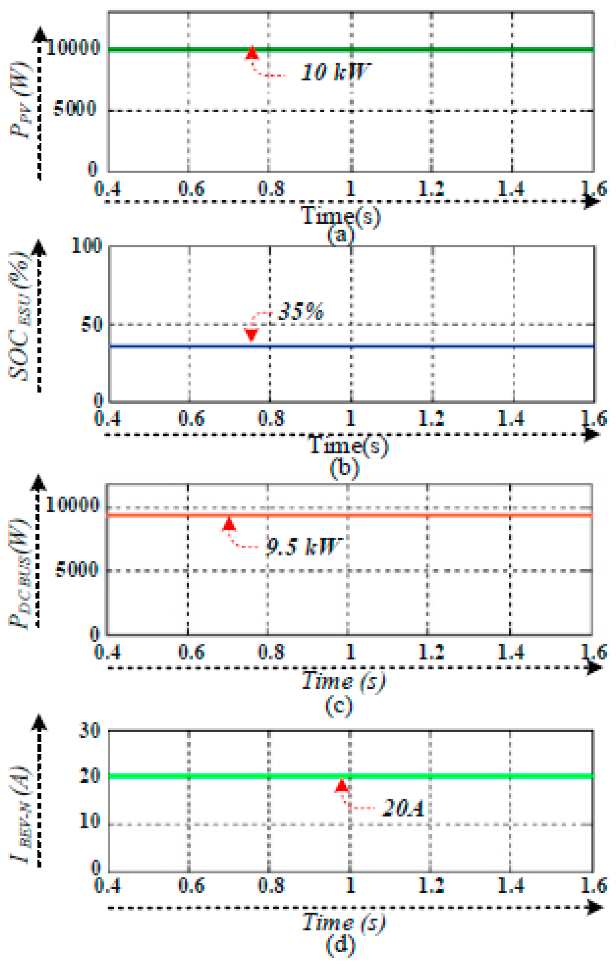
- (8)
- PV to ESU and BEV charging mode (160 W ≤ PPV ≤ 230 W).
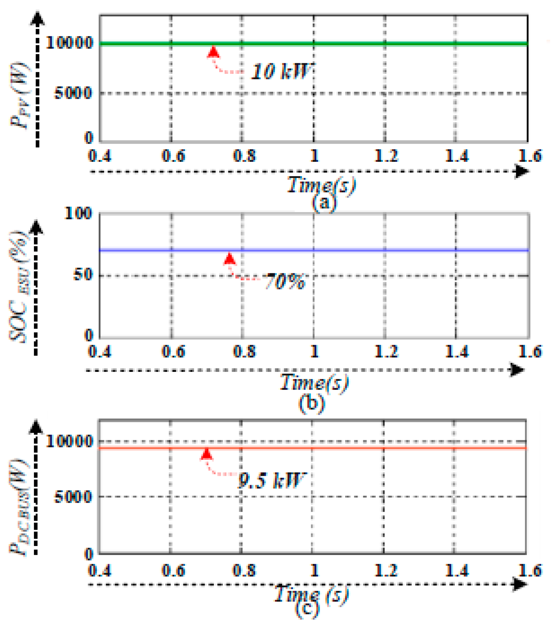
- (9)
- PV to ESU charging mode (PPV ≥ 230 W).
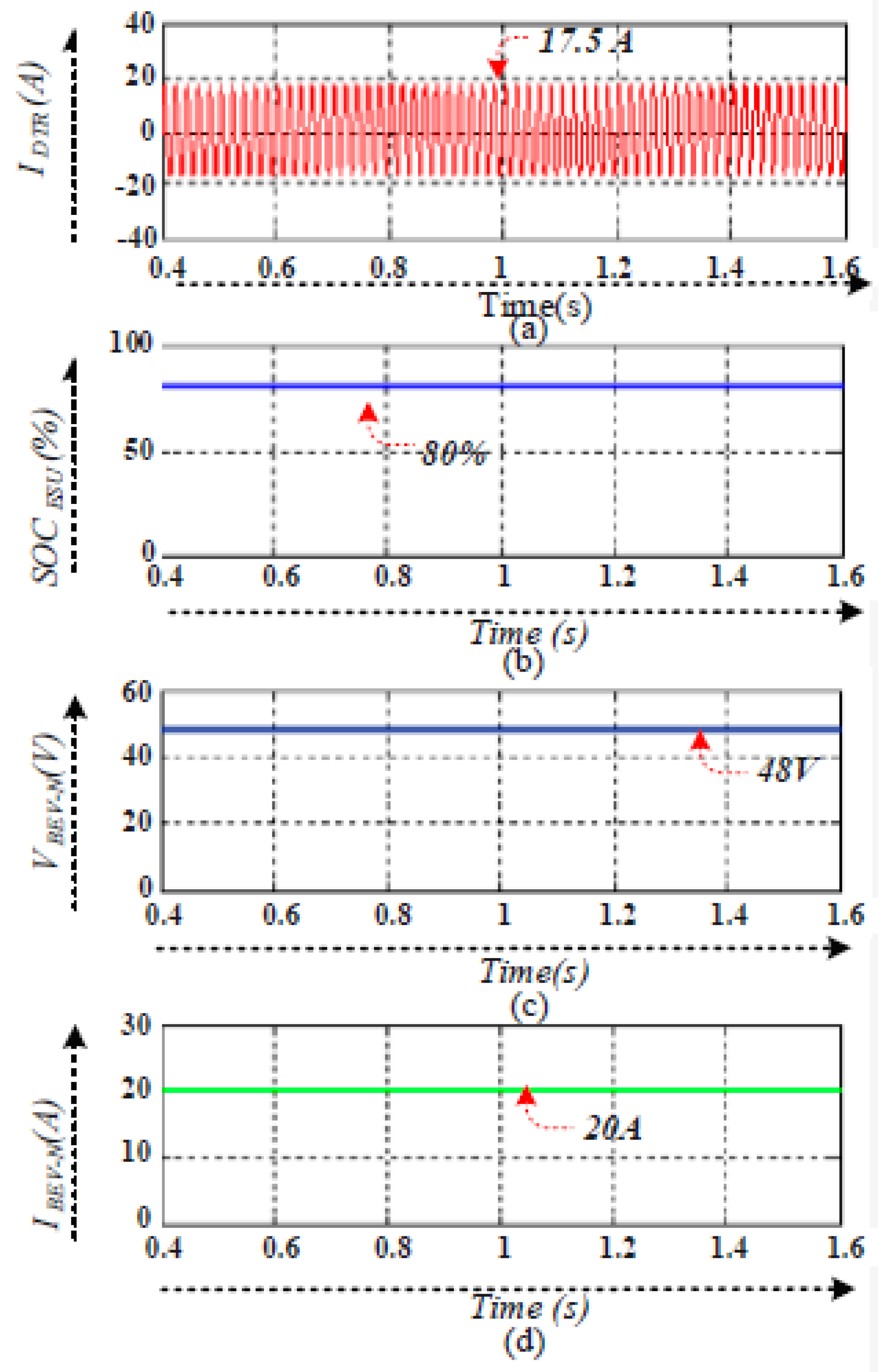
- (10)
- ESU to BEV charging mode (PPV < PPV MIN).
- (11)
- BEV to BEV charging mode (PPV < PPV MIN).
7. Conclusions
Author Contributions
Funding
Acknowledgments
Conflicts of Interest
Abbreviations
| VPV | Output voltage of the PV panel |
| IPV | Output current of the PV panel |
| PPV | PV power |
| VDTR | Voltage drawn from the utility grid |
| IDTR | Current drawn from the utility grid |
| IFB | Feedback current to the utility grid |
| IS1 | Boost converter current |
| VESU | ESU battery voltage |
| IESU | ESU battery current |
| PESU | Energy storage unit power |
| Iref | Battery charging current |
| PCS | Charging station power |
| PUG | Power drawn from the utility grid |
| BEV | Battery electric vehicle |
| G2V | Grid to vehicle |
| V2V | Vehicle to vehicle |
| ESU2V | ESU to vehicle |
| VDC BUS | DC bus voltage |
| PDC BUS | DC bus power |
| PBEV-N | BEVs power |
| PBEV-K | Particular BEV power |
| PPV REF-1 | PV power reference 1 |
| PPV REF-2 | PV power reference 2 |
| PPV REF-3 | PV power reference 3 |
| SOCESU | SOC of energy storage unit |
| SOC BEV | SOC of battery electric vehicle |
| VBEV-1–VBEV-3 | BEVs’ battery voltages |
| ISW | Isolation switch |
References
- Prakash, J.; Habib, G. A technology-based mass emission factors of gases and aerosol precursor and spatial distribution of emissions from on-road transport sector in India. Atmos. Environ. 2018, 180, 192–205. [Google Scholar] [CrossRef]
- Fulton, L.; Mejia, A.; Arioli, M.; Dematera, K.; Lah, O. Climate change mitigation pathways for Southeast Asia: CO2 emissions reduction policies for the energy and transport sectors. Sustainability 2017, 9, 1160. [Google Scholar] [CrossRef]
- Bose, R.K.; Srinivas chary, V. Policies to Reduce Energy Use and Environmental Emissions in the Transport Sector: A Case of Delhi City. Energy Policy 1997, 25, 1137–1150. [Google Scholar] [CrossRef]
- Emadi, A.; Lee, Y.J.; Rajashekara, K. Power electronics and motor drives in electric hybrid electric and plug—in hybrid electric vehicles. IEEE Trans. Ind. Electron. 2008, 55, 2237–2245. [Google Scholar] [CrossRef]
- Wang, C.S.; Stielau, O.H.; Covic, G.A. Design considerations for a contactless electric vehicle battery charger. IEEE Trans. Ind. Electron. 2005, 52, 1308–1314. [Google Scholar]
- Guerrero, J.M.; Loh, P.C.; Lee, T.L. Advanced control architectures for intelligent Microgrids-part II: Power quality, energy storage, and AC/DC Microgrids. IEEE Trans. Ind. Electron. 2013, 60, 1263–1270. [Google Scholar] [CrossRef]
- Preetham, G.; Shireen, W. Photovoltaic charging station for plug-in hybrid electric vehicles in a smart grid environment. In Proceedings of the IEEE PES Innovative Smart Grid Technologies, Washington, DC, USA, 16–20 January 2012; pp. 1–8. [Google Scholar]
- Vaidya, M.; Stefanakos, E.; Krakow, B.; Lamb, H.; Arbogast, T.; Smith, T. Direct DC-DC electric vehicle charging with a grid connected photovoltaic system. In Proceedings of the 25th IEEE Photovoltaic Specialists Conference, Washington, DC, USA, 13–17 May 1996; pp. 1505–1508. [Google Scholar]
- Fenton, J.; Hodkinson, R. Lightweight Electric/Hybrid Vehicle Design; Elsevier: Amsterdam, The Netherlands, 2001. [Google Scholar]
- Ruiz-Rodriguez, F.J.; Hernández, J.C.; Jurado, F. Voltage behaviour in radial distribution systems under the uncertainties of photovoltaic systems and electric vehicle charging loads. Int. Trans. Electr. Energy Syst. 2018, 28, e2490. [Google Scholar] [CrossRef]
- Yilmaz, M.; Krein, P.T. Review of Charging Power Levels and Infrastructure for Plug-In Electric and Hybrid Vehicles. In Proceedings of the IEEE International Electric Vehicle Conference (IEVC’12), Greenville, SC, USA, 4–8 March 2012. [Google Scholar]
- Chen, H.; Hu, Z.; Luo, H.; Qin, J.; Rajagopal, R.; Zhang, H. Design and Planning of a Multiple-charger Multiple-port Charging System for PEV Charging Station. IEEE Trans. Smart Grid 2017, 10, 173–183. [Google Scholar] [CrossRef]
- Chokkalingam, B.; Padmanaban, S.; Siano, P.; Krishnamoorthy, R.; Selvaraj, R. Real-Time Forecasting of EV Charging Station Scheduling for Smart Energy Systems. Energies 2017, 10, 377. [Google Scholar] [CrossRef]
- Sanchez-Sutil, F.; Hernández, J.C.; Tobajas, C. Overview of electrical protection requirements for integration of a smart DC node with bidirectional electric vehicle charging stations into existing AC and DC railway grids. Electric Power Syst. Res. 2015, 122, 104–118. [Google Scholar] [CrossRef]
- Du, Y.; Zhou, X.; Bai, S.; Lukic, S.; Huang, A. Review of non-isolated bi-directional DC-DC converters for plug-in hybrid electric vehicle charge station application at municipal parking decks. In Proceedings of the Applied Power Electronics Conference and Exposition (APEC), Palm Springs, CA, USA, 21–25 February 2010; pp. 1145–1151. [Google Scholar]
- Salas, V.; Olias, E.; Barrado, A.; Lazaro, A. Review of the maximum power point tracking algorithms for stand-alone photovoltaic systems. Sol. Energy Mater. Sol. Cells 2006, 90, 1555–1578. [Google Scholar] [CrossRef]
- Hernandez, J.C.; Sutil, F.S. Electric vehicle charging stations feeded by renewable: PV and train regenerative braking. IEEE Latin Am. Trans. 2016, 14, 3262–3269. [Google Scholar] [CrossRef]
- Pickard, W.F.; Shen, A.Q.; Hansing, N.J. Parking the power: Strategies and physical limitations for bulk energy storage in supply–demand matching on a grid whose input power is provided by intermittent sources. Renew. Sustain. Energy Rev. 2009, 13, 1934–1945. [Google Scholar] [CrossRef]
- Esram, T.; Chapman, P.L. Comparison of photovoltaic array maximum power point tracking techniques. IEEE Trans. Energy Convers. 2007, 22, 439–449. [Google Scholar] [CrossRef]
- Xiao, B.; Hang, L.; Mei, J.; Riley, C.; Tolbert, L.M.; Ozpineci, B. Modular cascaded H-bridge multilevel PV inverter with distributed MPPT for grid-connected applications. IEEE Trans. Ind. Appl. 2015, 51, 1722–1731. [Google Scholar] [CrossRef]
- Carrasco, J.M.; Franquelo, G.; Bialasiewicz, T.; Galvan, E.; Guisado, R.C.P.; Prats, A.M.; Le´on, J.I.; Moreno-Alfonso, N. Power-electronic systems for the grid integration of renewable energy sources: A survey. IEEE Trans. Ind. Electron. 2006, 53, 1002–1016. [Google Scholar] [CrossRef]
- Hamilton, C.; Gamboa, G.; Elmes, J.; Kerley, R.; Arias, A.; Pepper, M.; Shen, J.; Batarseh, I. System architecture of a modular direct-DC PV charging station for plug-in electric vehicles. In Proceedings of the IECON 2010—36th Annual Conference on IEEE Industrial Electronics Society, Glendale, AZ, USA, 7–10 November 2010; pp. 2516–2520. [Google Scholar]
- Shaukat, N.; Khan, B.; Ali, S.M.; Mehmood, C.A.; Khan, J.; Farid, U.; Majid, M.; Anwar, S.M.; Jawad, M.; Ullah, Z. A survey on electric vehicle transportation within smart grid system. Renew. Sustain. Energy Rev. 2017, 81, 1329–1349. [Google Scholar] [CrossRef]
- Fathima, A.H.; Palanisamy, K.; Sanjeevikumar, P.; Umashankar, S. Intelligence-based battery management and economic analysis of an optimized dual-Vanadium Redox Battery (VRB) for a Wind-PV HYBRID SYSTEM. Energies 2018, 11, 2785. [Google Scholar] [CrossRef]
- Zhao, Z.; Hu, J.; Chen, H. Bus Voltage Control Strategy for Low Voltage DC Microgrid Based on AC Power Grid and Battery. In Proceedings of the 2017 IEEE International Conference on Energy Internet (ICEI), Beijing, China, 17–21 April 2017; pp. 349–354. [Google Scholar]
- Khajehoddin, S.A.; Karimi-Ghartemani, M.; Jain, P.K.; Bakhshai, A. DC-bus design and control for a single-phase grid-connected renewable converter with a small energy storage component. IEEE Trans. Power Electron. 2013, 28, 3245–3254. [Google Scholar] [CrossRef]
- Li, X.; Guo, L.; Wang, C.; Zhang, S.; Rong, Y.; Feng, Y.; Li, Y. Robust and autonomous DC bus voltage control and stability analysis for a DC microgrid. In Proceedings of the 2016 IEEE 8th International Power Electronics and Motion Control Conference (IPEMC-ECCE Asia), Hefei, China, 22–26 May 2016; pp. 3708–3714. [Google Scholar]
- Chen, D.; Xu, L.; Yao, L. DC voltage variation based autonomous control of DC microgrids. IEEE Trans. Power Deliv. 2013, 28, 637–648. [Google Scholar] [CrossRef]
- Yoon, S.G.; Kang, S.G. Economic microgrid planning algorithm with electric vehicle charging demands. Energies 2017, 10, 1487. [Google Scholar] [CrossRef]
- Ul-Haq, A.; Cecati, C.; Al-Ammar, E.A. Modeling of a Photovoltaic-Powered Electric Vehicle Charging Station with Vehicle-to-Grid Implementation. Energies 2016, 10, 4. [Google Scholar] [CrossRef]
- Zhou, D.; Al-Durra, A.; Matraji, I.; Ravey, A.; Gao, F. Online Energy Management Strategy of Fuel Cell Hybrid Electric Vehicles: A Fractional-Order Extremum Seeking Method. IEEE Trans. Ind. Electron. 2018, 65, 6787–6799. [Google Scholar] [CrossRef]
- Dragicevic, T.; Guerrero, J.M.; Vasquez, J.C.; Skrlec, D. Supervisory control of an adaptive-droop regulated DC microgrid with battery management capability. IEEE Trans. Power Electron. 2014, 29, 695–706. [Google Scholar] [CrossRef]
- Demirok, E.; Gonzalez, P.C.; Frederiksen, K.H.; Sera, D.; Rodriguez, P.; Teodorescu, R. Local reactive power control methods for overvoltage prevention of distributed solar inverters in low-voltage grids. IEEE J. Photovolt. 2011, 1, 174–182. [Google Scholar] [CrossRef]
- Karimi-Ghartemani, M.; Khajehoddin, S.A.; Jain, P.; Bakhshai, A. A systematic approach to DC-bus control design in single-phase grid-connected renewable converters. IEEE Trans. Power Electron. 2013, 28, 3158–3166. [Google Scholar] [CrossRef]
- Haghbin, S.; Lundmark, S.; Alakula, M.; Carlson, O. Grid-connected integrated battery chargers in vehicle applications: Review and new solution. IEEE Trans. Ind. Electron. 2013, 60, 459–473. [Google Scholar] [CrossRef]
- Dallinger, D.; Wietschel, M. Grid integration of intermittent renewable energy sources using price-responsive plug-in electric vehicles. Renew. Sustain. Energy Rev. 2012, 16, 3370–3382. [Google Scholar] [CrossRef] [Green Version]
- Rahman, I.; Vasant, P.M.; Singh, B.S.M.; Abdullah-Al-Wadud, M.; Adnan, N. Review of recent trends in optimization techniques for plug-in hybrid, and electric vehicle charging infrastructures. Renew. Sustain. Energy Rev. 2016, 58, 1039–1047. [Google Scholar] [CrossRef]
- Escudero-Garzas, J.J.; Seco-Granados, G. Charging station selection optimization for plug-in electric vehicles: An oligopolistic game-theoretic framework. In Proceedings of the Innovative Smart Grid Technologies, Washington, DC, USA, 16–20 January 2012; pp. 1–8. [Google Scholar]
- Wang, M.; Ismail, M.; Zhang, R.; Shen, X.S.; Serpedin, E.; Qaraqe, K. A semi-distributed V2V fast charging strategy based on price control. In Proceedings of the 2014 IEEE Global Communications Conference, Austin, TX, USA, 8–12 December 2014; pp. 4550–4555. [Google Scholar]
- Hernández, J.C.; Sanchez-Sutil, F.; Vidal, P.G.; Rus-Casas, C. Primary frequency control and dynamic grid support for vehicle-to-grid in transmission systems. Int. J. Electr. Power Energy Syst. 2018, 100, 152–166. [Google Scholar] [CrossRef]
- Bhatti, A.R.; Salam, Z.; Ashique, H. Electric vehicle charging using photovoltaic based microgrid for remote islands. Energy Procedia 2016, 103, 213–218. [Google Scholar] [CrossRef]
- Tran, V.T.; Sutanto, D.; Muttaqi, K.M. The state of the art of battery charging infrastructure for electrical vehicles: Topologies, power control strategies, and future trend. In Proceedings of the 2017 Australasian Universities Power Engineering Conference (AUPEC), Melbourne, VIC, Australia, 19–22 November 2017; pp. 1–6. [Google Scholar]
- Goli, P.; Shireen, W. PV Integrated Smart Charging of PHEVs Based on DC Link Voltage Sensing. IEEE Trans. Smart Grid 2014, 5, 1421–1428. [Google Scholar] [CrossRef]
- Sbordone, D.; Bertini, I.; Di Pietra, B.; Falvo, M.C.; Genovese, A.; Martirano, L. EV fast charging stations and energy storage technologies: A real implementation in the smart micro grid paradigm. Electr. Power Syst. Res. 2015, 120, 96–108. [Google Scholar] [CrossRef]
- Nagarajan, A.; Shireen, W. Grid connected residential photovoltaic energy systems with Plug-In Hybrid electric Vehicles (PHEV) as energy storage. In Proceedings of the IEEE PES General Meeting, Providence, RI, USA, 25–29 July 2010; pp. 1–5. [Google Scholar]


| CS Parameters | Mode-1 | Mode-2 | Mode-3 | Mode-4 | Mode-5 | Mode-6 | Mode-7 | Mode-8 | Mode-9 | Mode-10 | Mode-11 |
|---|---|---|---|---|---|---|---|---|---|---|---|
| PPV (W) | 1500 | 1500 | 1500 | 1500 | 7500 | 7500 | 7500 | 10,000 | 10,000 | 0 | 0 |
| IDTR (A) | 17.5 | 17.5 | 12 | 12 | 12 | 17.5 | 19.7 | NC | NC | 17.5 | 17.5 |
| SOCESU (%) | 50 | 70 | 35 | 90 | 30 | NC | 90 | 35 | 70 | 80 | 25 |
| IESU (A) | 12 | NC | 12 | NC | 120 | NC | NC | 120 | 120 | 15 | NC |
| PDC-GRID (W) | 5340 | 1425 | 11250 | 11250 | 11250 | 7125 | 7125 | 9500 | 9500 | 4800 | 1000 |
| PBEV-N (W) | 1000 | 1000 | NA | 1000 | 1000 | 960 | NA | 1000 | FC | 1000 | 950 |
| IBEV-N (A) | 20 | 20 | NA | 20 | 20 | 20 | NA | 20 | FC | 20 | 19 |
| Ref. Papers | Microgrid Type | On board Storage System | Nonrenewable Sources Connected | Renewable Sources | Utility Grid Connected | Type of Charging | Control Strategy | V2V Charging | Pros and Cons |
|---|---|---|---|---|---|---|---|---|---|
| [41] | AC | YES | Two Diesel Generators | PV | YES | On board | Load demand | YES | Pros: ● Generators used; Uninterrupted supply Cons: ● Conversion needs for charging |
| [42] | Hybrid | YES | NO | PV and WIND | YES | On board | Power Control | NO | Pros: ● High power density converter used for charging Cons: ● PV to grid stabilize the demand |
| [43] | DC | YES | NO | PV | YES | Off board | DC link voltage | NO | Pros: ● Distribution Transformer upgradation not required Cons: ● Not used ESU for store PV power |
| [44] | AC | YES | NO | NO | YES | Off board | Power Control Strategies | NO | Pros: ● Smart charging Cons: ● AC distribution network, increases conversion losses |
| [45] | DC | NO | NO | PV | YES | On board | Power Control | NO | Pros: ● Flexible EV charging Cons: ● Overloading of grid not realized |
| Proposed | Hybrid | YES | NO | PV | YES | Off board | PV and DC link Power | YES | Pros: ● Provide optimum usage of PV utilization and considering grid overloading, bidirectional power flow for V2V Cons: ● High Cost of ESU installation |
© 2019 by the authors. Licensee MDPI, Basel, Switzerland. This article is an open access article distributed under the terms and conditions of the Creative Commons Attribution (CC BY) license (http://creativecommons.org/licenses/by/4.0/).
Share and Cite
Savio, D.A.; Juliet, V.A.; Chokkalingam, B.; Padmanaban, S.; Holm-Nielsen, J.B.; Blaabjerg, F. Photovoltaic Integrated Hybrid Microgrid Structured Electric Vehicle Charging Station and Its Energy Management Approach. Energies 2019, 12, 168. https://doi.org/10.3390/en12010168
Savio DA, Juliet VA, Chokkalingam B, Padmanaban S, Holm-Nielsen JB, Blaabjerg F. Photovoltaic Integrated Hybrid Microgrid Structured Electric Vehicle Charging Station and Its Energy Management Approach. Energies. 2019; 12(1):168. https://doi.org/10.3390/en12010168
Chicago/Turabian StyleSavio, Dominic A., Vimala A. Juliet, Bharatiraja Chokkalingam, Sanjeevikumar Padmanaban, Jens Bo Holm-Nielsen, and Frede Blaabjerg. 2019. "Photovoltaic Integrated Hybrid Microgrid Structured Electric Vehicle Charging Station and Its Energy Management Approach" Energies 12, no. 1: 168. https://doi.org/10.3390/en12010168