Experimental Research on the Thermal Performance and Semi-Visualization of Rectangular Flat Micro-Grooved Gravity Heat Pipes

1
School of Energy and Environmental Engineering, Hebei University of Technology, Tianjin 300401, China
2
Department of Comprehensive Management, CNOOC Energy Conservation & Environmental Protection Service Co., Ltd., Tianjin 300452, China
*
Authors to whom correspondence should be addressed.
Energies 2018, 11(9), 2480; https://doi.org/10.3390/en11092480
Submission received: 24 August 2018
/
Revised: 10 September 2018
/
Accepted: 14 September 2018
/
Published: 18 September 2018
Abstract
:To strengthen the heat dissipating capacity of a heat pipe used for integrated insulated gate bipolar transistors, as an extension of our earlier work, the effect of micro-groove dimension on the thermal performance of flat micro-grooved gravity heat pipe was studied. Nine pipes with different depths (0.4 mm, 0.8 mm, 1.2 mm) and widths (0.4 mm, 0.8 mm, 1.2 mm) were fabricated and tested under a heating load range from 80 W to 180 W. The start-up time, temperature difference, relative thermal resistance and equivalent thermal conductivity were presented as performance indicators by comparison of flat gravity heat pipes with and without micro-grooves. Results reveal that the highest equivalent thermal conductivity of the flat micro-grooved gravity heat pipes is 2.55 times as that of the flat gravity heat pipe without micro-grooves. The flat gravity heat pipes with deeper and narrower micro-grooves show better thermal performance and the optimal rectangular micro-groove dimension among the selected options is determined to be 1.2 mm (depth) × 0.4 mm (width). Furthermore, the liquid–vapor phase behaviors were observed to verify the heat transfer effects and analyze the heat transfer mechanism of the flat micro-grooved heat pipes.
1. Introduction
The demand for boosting modern transportation requires excellent performance of integrated insulated gate bipolar transistors (IGBTs) as driving systems. The technologies of large-scale integrated circuits and extra microfabrication enable IGBTs to hold thousands of transistors, and the operating characteristic of high-frequency switching necessitates an enormous capacity for heat dissipation. Due to the flexible configuration and effective performance, flat heat pipes are widely applied in cooling electrical devices [1] to prevent the malfunction or irreversible damage of electronic components [2]. A plate gravity heat pipe (PGHP) or flat gravity heat pipe (FGHP) is a cavity of small thickness partially filled with a two-phase working fluid [3]. The liquid turns into vapor by absorbing heat from the interface at an evaporation section and the vapor condenses back into liquid at a condensation section by releasing the heat. For a flat micro-grooved gravity heat pipe (FMGHP), similar to a FGHP, it also functions as a gravity-type heat pipe which operates in a vertical orientation. The evaporation section and the condensation section lie in the bottom end and the top end of the heat pipe, respectively. The working liquid flows as it is driven by a pressure difference. The liquid returns to the evaporation section through the combined effect of gravity and the capillary action generated by the micro-grooves [4]. Micro-grooves act as a kind of wick on the inner surface of the evaporation and condensation sections to help uniformly distribute liquid streams across the surface and create enhanced heat transfer performance [5]. Thus, FGHPs combined with micro-grooves are simple and effective to enhance heat transfer for removing heat.
In 1981, Tuckerman et al. [6] pioneered microchannel cooling. The use of high-aspect ratio channels could increase surface area and reduce thermal resistance to some extent. Some micro-groove geometries with a U-shaped [7], triangular [8,9], trapezoidal [10,11] and rectangular [12] cross-sections, for example, were studied in the literature. Particularly, flat heat pipes with rectangular micro-grooves are widely considered in research and utilization for their easy manufacture. Hopkins et al. [13] performed experiments with rectangular micro-grooved flat heat pipes. They concluded that narrower or deeper grooved wick structures had better heat removal performance.
Do et al. [14] developed a mathematical model for predicting the thermal performance of a flat heat pipe with a rectangular micro-grooved wick structure. By using the proposed model, the optimum width and height of the micro-groove based on the original model was determined with respect to the maximum heat transport rate of the flat micro-grooved heat pipes. The results of the thermal optimization showed that a narrow and deep micro-groove had a relatively high heat transport rate in certain dimensional scopes.
With the numerical model developed by Saad et al. [15], an axially-grooved flat heat pipe was investigated. They found that the dimensions of the rectangular micro-grooves considerably affected the hydrodynamic parameters. It was concluded that for a given groove width (depth), the maximum power increased with the groove depth (width). Consequently, good thermal performance was obtained in deep and narrow micro-grooves. In their following study [16], flat micro-grooved heat pipes with rectangular and triangular micro-grooves were compared, indicating the rectangular micro-grooves allowed for higher capillary limits than the triangular micro-grooves.
Gillot et al. [17] studied flat silicon heat pipes used as thermal spreaders in power devices such as IGBTs. The results showed that when using a rectangular micro-grooved silicon heat pipe, heat was more uniformly distributed and thermal resistance was decreased. For a heat transfer coefficient of 3 kW/(m·K), the thermal resistance for the flat silicon heat pipe with 100 μm high micro-grooves was decreased by about 31% compared with the plain prototype without any micro-grooves.
In the literature of Nagayama et al. [12], they reported a simplified theoretical analysis to optimize the micro-groove size for straight microchannels on a flat silicon heat pipe. The flat heat pipe made of silicon substrate had a grooved area of 15 × 70 mm2. When the micro-groove height was fixed at 100 μm, the optimal value for width was 100 μm. Through conducting experiments, they concluded that the driving force determined by the geometry played the primary role on the thermal performance of heat pipes, while the number of micro-grooves played the secondary role on the thermal performance.
The exploration for flat heat pipes further combined with visualization can provide a better insight of the characteristics of liquid–vapor phase behaviors. Wong et al. [7] investigated the working characteristics of a micro-grooved heat pipes. With visualization, the behavior of the working fluid was observed and the variation in evaporator thermal resistance with increasing heating load was measured.
The aforementioned literature confirms the necessity and value for studying flat micro-grooved heat pipes. Besides, in our previous work [18], we carried out the experimental study on an FGHP. The effects of various heating loads and fluid filling ratios on the thermal performance were observed and studied at unsteady state. As an extension of the previous work, FMGHPs were studied in this paper. Considering the capillary limit and further avoiding dry-out happening during the evaporation section, nine FMGHPs with different rectangular micro-groove dimensions were designed and manufactured. Experiments were carried out to investigate their thermal performance. The start-up time, temperature difference, relative thermal resistance and equivalent thermal conductivity as thermal performance indicators were obtained under different heating loads by comparing FMGHPs with FGHPs to determine an optimal rectangular micro-groove dimension. Furthermore, semi-visualization was used to validate the heat transfer effect by analyzing liquid–vapor phase behaviors.
2. Experimental
2.1. Fabrication of FMGHPs
The experimental setup is similar to our earlier work [18], except for the micro-groove part of the FMGHPs. The semi-visualization of the FMGHP mainly consists of three parts: the base plate (270 mm × 160 mm × 16 mm) and the frame structure (270 mm × 160 mm × 6 mm with an internal cavity of 210 mm × 100 mm × 6 mm) made of aluminum alloy, and a visualized window (240 mm × 130 mm × 10 mm) made of quartz glass. These were tightened with screws. The base plate has an internal space with a dimension of 100 mm × 2.5 mm × 210 mm for filling with working fluid. Rectangular micro-grooves were processed on the internal surface of the base plate and described by width (w) × depth (d). Figure 1 shows a fabricated FMGHP (a) and the structure of the micro-grooves in FMGHP from an A–A cross-section view (b).
The nine FMGHPs have the same micro-groove quantity (40) and different micro-groove dimensions, which are divided into three groups according to the three widths marked with “w” (0.4 mm, 0.8 mm, 1.2 mm) in Figure 1b. Three kinds of widths of micro-grooves are involved, and different groove widths are obtained through adjusting the widths of fins marked with “f” in Figure 1b, which are the middle parts between two micro-grooves. Besides, there are three depths (0.4 mm, 0.8 mm, 1.2 mm) marked with “h” in Figure 1b for each width. The specific dimensions of the micro-grooves are shown in Table 1.
Furthermore, the procedures of cleaning, drying, sealing, tightness testing, vacuuming and filling were carried out in sequence for the FMGHP, which are the same as those in our previous work [18]. The working fluid used in the FMGHPs is acetone, due to its working temperature, saturation vapor pressure, and some other beneficial properties such as its liquid transmission coefficient and thermal stability.
2.2. Experimental System
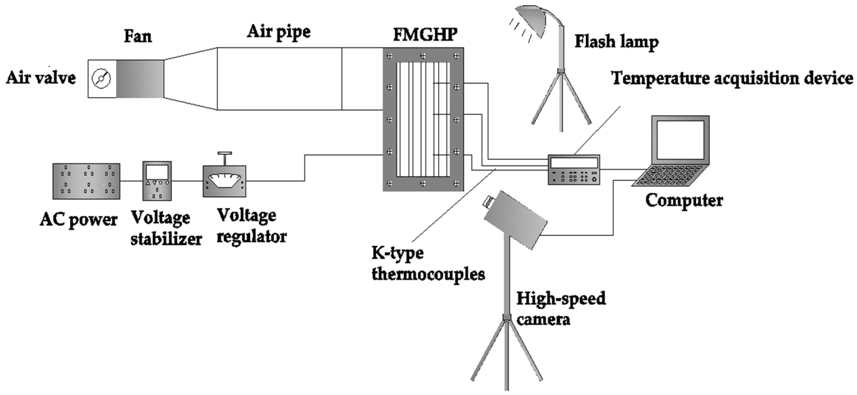
The experimental system includes the semi-visualization FMGHP, a heating system, a cooling system and a data acquisition system. The semi-visualization FMGHP was experimented with in a vertical orientation. In the heating system, the heat for the evaporation section was provided by a heat block (100 mm × 90 mm × 10 mm), which was tightened to the external surface of the evaporation section (with a width of 100 mm and a height of 90 mm). In the cooling system, the condensation section (with a width of 100 mm and a height of 90 mm) of the FMGHP was cooled by forced air at a constant temperature and flow rate. There is a transition/adiabatic section between the evaporation and condensation sections, which has a width of 100 mm and a height of 30 mm. In the data acquisition system, three K-type thermocouples were arranged at selected positions on the Z-axis to monitor the temperature variation at the evaporation, transition and condensation sections. The visualization was performed using a high-speed camera (model i-SPEED3). In addition, the heating and cooling system were wrapped in insulation cotton to minimize heat loss during the experiment. The experimental system is shown in Figure 2.
2.3. Experimental Conditions
The FMGHPs were evacuated down to a pressure of 1 × 10⁻³ Pa and then filled with acetone. A filling ratio of 48% is adopted according to the optimal filling ratio for FGHPs reported in our earlier work [18], although the heat pipes in this work are distinguished from those without micro-grooves. The thermal performance experiments of each FMGHP at different heating loads (80–180 W) were carried out at least three times.
3. Thermal Performance Indicators
The start-up time, temperature difference, relative thermal resistance, and equivalent thermal conductivity are used as four indicators of the thermal performance of FMGHPs.
(i) The start-up time denotes the time from the beginning of heating at the evaporation section to the beginning of the FMGHPs working. The work starting can be analyzed by the first obvious fluctuation of the temperature at the evaporation section under various heating loads [18].
(ii) The temperature difference ∆T at stable operation between the evaporation and condensation sections in the cavity of the FMGHP is measured as another indicator. It is shown as Equation (1) [18].
where Te and Tc represent the average temperatures in the evaporation and condensation sections of the heat pipe, K, respectively.
(iii) Thermal resistance refers to the required temperature difference to transfer per unit heat. In the present work, the focus is given to the relative resistance of the working fluid circulating between the evaporation and condensation sections at stable operation. The relative thermal resistance is defined as Equation (2) [18].
where R is the relative thermal resistance of the working fluid, K/W, and Q is the heating load, W.
(iv) The equivalent thermal conductivity at stable operation is defined as Equations (3) and (4) [12,19].
where k is the equivalent thermal conductivity, W/(m·K); A represents the cross-sectional area of the vapor cavity in the FMGHP, m2; leff is the effective length of the FMGHP, m; and le, lt and lc denote the lengths of the evaporation, transition and condensation sections, m, respectively.
4. Results and Discussion
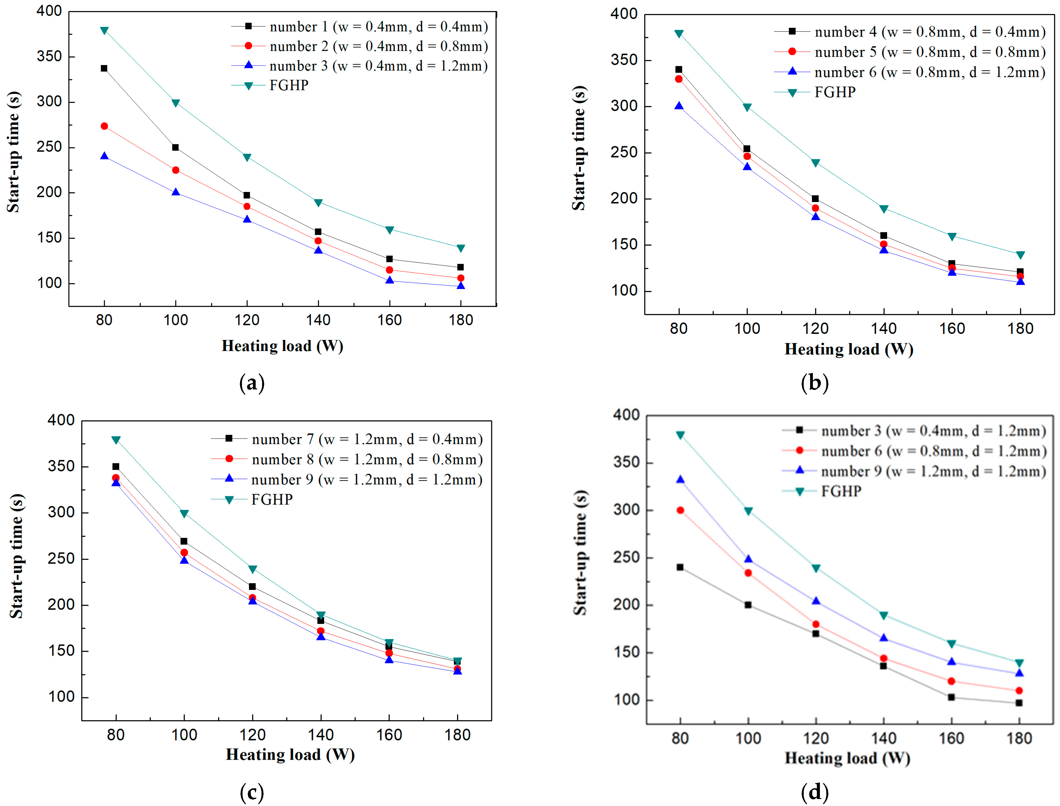
4.1. The Effects of FMGHP Micro-Grooves on Start-Up Time
The start-times of the FGHP and FMGHPs with different micro-groove depths (0.4 mm, 0.8 mm and 1.2 mm) decrease with an increase in heating load, as shown in Figure 3a (w = 0.4 mm), Figure 3b (w = 0.8 mm) and Figure 3c (w = 1.2 mm), respectively. In the FMGHPs and FGHP, at the beginning of heating in the evaporation section, the interior working fluid is calm, and the average temperature of the working fluid is low. With the constant input of heat, the working fluid absorbs heat continuously, which results in the superheating of the working fluid. The energy accumulates to generate nucleation and the obvious fluctuation of the temperature in the evaporation section occurs. Then, the heat pipe starts to operate. To accumulate the same amount of heat for the start-up, the higher heating input leads to the shorter response time required for the FGHP and FMGHPs.
When the heating load remains constant, the start-up time of FMGHPs decreases with the increasing depth of the micro-grooves. The FGHP without micro-grooves has the longest start-up time. FMGHPs three, six and nine have the shortest start-up times as shown in Figure 3a–c, respectively. When the heat pipe has deeper micro-grooves, the working fluid filling into the micro-grooves is closer to the heating block, which enhances the heat transfer from the heat block to the working fluid. Besides, the contact surface between the working fluid and the heated evaporation section of the heat pipe is increased. The working fluid in the micro-grooves can obtain more heat per unit time from a larger contact surface. Therefore, the response time of the FMGHP is shortened.
Figure 3d compares the three FMGHPs with a FGHP. It is shown that the FMGHPs have the same depth of 1.2 mm and different widths. The start-up time of the FMGHPs decreases with a decreasing width of the micro-grooves at each heating load. For instance, when the heating load is 120 W and the width is 0.4 mm, 0.8 mm and 1.2 mm, the shortest start-up times are 170 s, 180 s and 204 s, respectively. They decline by 29%, 25% and 15% compared with the FGHP without micro-grooves. FMGHP 3, with narrower and deeper grooves, has the shortest start-up time at each heating load. The bigger capillary force due to the narrower micro-grooves primarily affects this performance [1,5]. When the heat pipe has narrower micro-grooves, the condensed working fluid draws back to the evaporation section in less time with the effect of bigger capillary force and gravity. Thus, the response time of the FMGHP is further shortened.
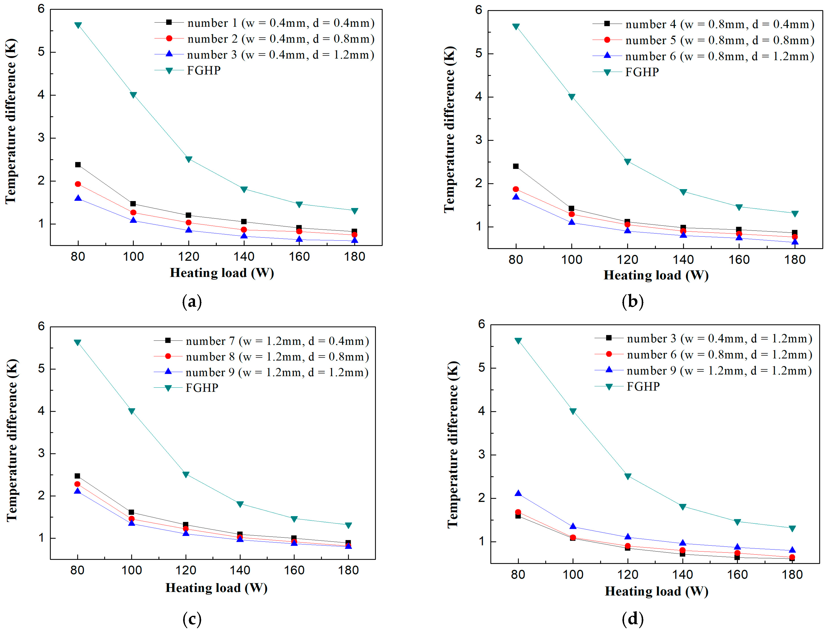
4.2. The Effects of Micro-Grooves on FMGHPs on Temperature Difference
In Figure 4a (w = 0.4 mm), Figure 4b (w = 0.8 mm) and Figure 4c (w = 1.2 mm), it is shown that the temperature differences of the FGHP and FMGHPs with different depths (0.4 mm, 0.8 mm and 1.2 mm) of micro-grooves decrease as the heating load increases. When the heat pipe operates steadily, lots of saturated vapor circulates between the evaporation and condensation sections. Liquid absorbs heat in the evaporation section and vapor releases heat in the condensation section. Plenty of latent heat is transferred through the formation and split of bubbles. When the heating load increases, more bubbles are generated to transfer more heat. Meanwhile, the disturbance to the boiling working fluid resulting from the movement of the bubbles is enhanced near the heating surface. The temperatures in the both the evaporation and condensation sections of FMGHPs and the FGHP are close to uniform. Therefore, the temperature difference between the evaporation and condensation sections is reduced and the heat transfer capacity of the heat pipes is strengthened.
When the heating load is kept constant, the temperature difference of the FMGHPs decreases with an increase in micro-groove depth. The lowest temperature differences occur in the curve of FMGHP 3, FMGHP 6 and FMGHP 9 in Figure 4a–c, respectively. The FGHP without micro-grooves has the highest temperature difference. There are three main reasons for this. Firstly, deep micro-grooves enhance the capillary force which is required to draw the condensed liquid from the condensation section back into the evaporation section [20], and the capillary force affects jointly with gravity in FMGHPs. The increased capillary force enhances the thermal performance of FMGHPs by reducing the thickness of the condensed liquid film. Secondly, the nucleation rate increases in the presence of a scratched surface compared to that of a smooth surface [21], which makes it easier to form bubbles [22,23], so the micro-grooves create conditions for the formation of bubbles in the evaporation section. The increased number of bubbles and the enhanced disturbance of the working fluid lead to the better heat transfer ability of FMGHPs. Thirdly, the micro-grooves in FMGHPs enlarge the cross-sectional area of the vapor section and further reduce the flow resistance in the vapor section [12,14]. The increased depth can also cause a reduction in the flow resistance in the micro-grooves because the additional flow resistance due to liquid–vapor interfacial shear stress is decreased [14]. These influences contribute to a decrease in the temperature difference between the evaporation and condensation sections and an increase in the thermal performance of the FMGHPs. On the contrary, the deeper micro-grooves also increase the conduction path between the micro-grooved base and the fin top of the micro-grooves, which adds additional thermal resistance to some extent [2]. Nevertheless, the three factors stated above still predominantly reduce the temperature difference and strengthen the heat transfer of the FMGHPs.
By comparing FMGHP 3, FMGHP 6 and FMGHP 9 with FGHP in Figure 4d, it is shown that the temperature difference of the three FMGHPs decreases with the decreasing width of the micro-grooves at each heating load. For instance, when the heating load is 120 W, the temperature differences are 0.848 K, 0.901 K and 1.100 K respectively, which are declined by 66%, 64% and 56%, compared with that of the FGHP without micro-grooves. The lowest temperature difference is obtained by FMGHP 3. In this case, the micro-groove width is reduced, and the fin thickness is increased without changing the depth and quantity of the micro-grooves. This leads to a higher capillary pumping force and better thermal performance. In fact, the narrower width brings negative effects. The reduction in width causes a reduction of the cross-sectional area in the micro-grooves, which results in higher flow resistance [14]. However, the driving force from the pressure difference plays the primary role on the thermal performance while the heat transfer area and the liquid–vapor phase change area play the secondary role [13]. Therefore, in this case, these counteracting influences ultimately contribute to an increase in the temperature difference and thermal performance of the FMGHPs.
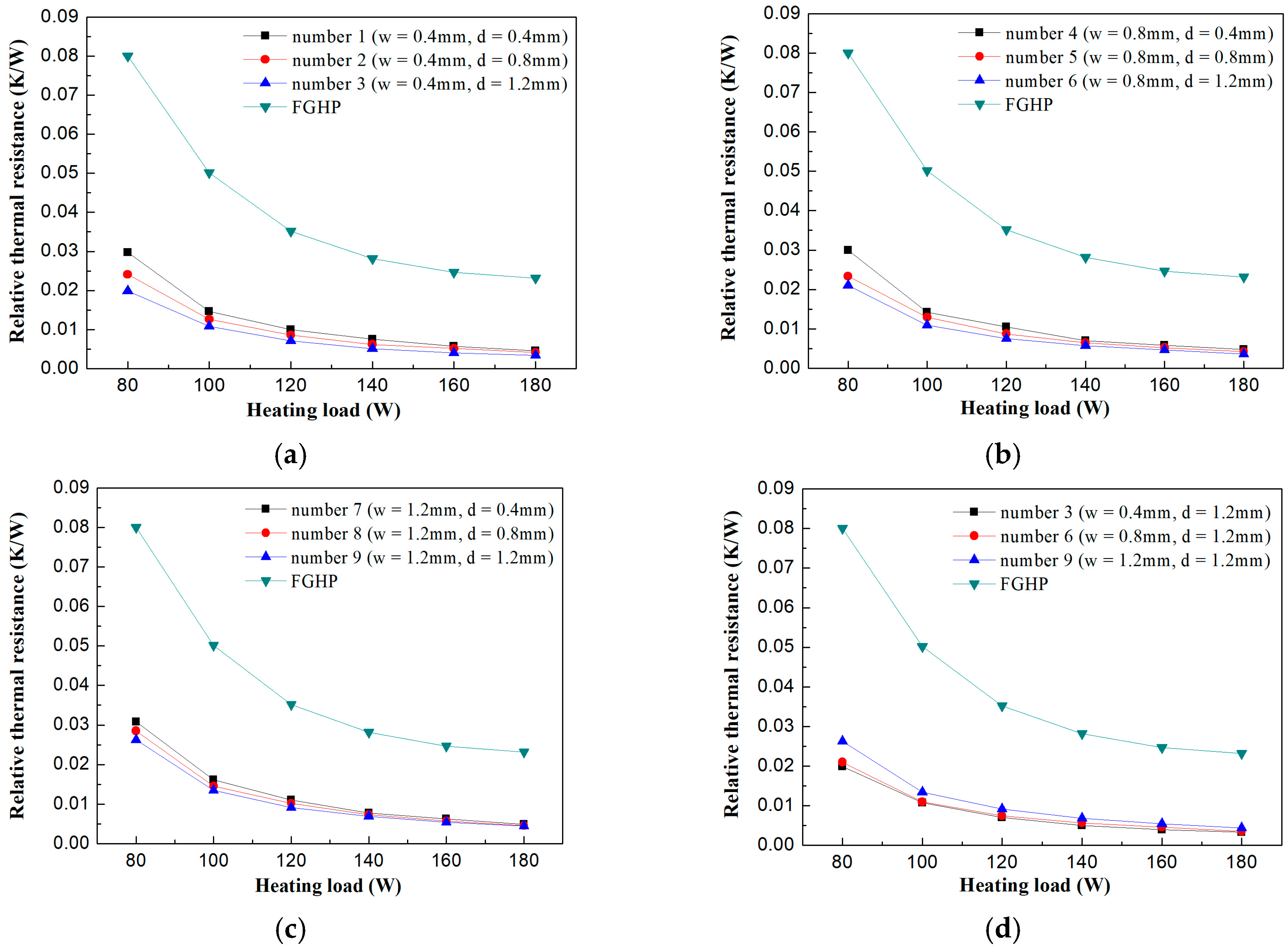
4.3. The Effects of Micro-Grooves on FMGHPs on Relative Thermal Resistance
The curve trend of the relative thermal resistance at different heating loads and the influence analysis for the micro-groove dimensions are similar to that of the temperature difference. The relative thermal resistances of FGHP and FMGHPs with different depths (0.4 mm, 0.8 mm and 1.2 mm) of micro-grooves decrease with increasing heating load, described in Figure 5a (w = 0.4 mm), Figure 5b (w = 0.8 mm) and Figure 5c (w = 1.2 mm), respectively. When the heating load remains constant, the relative thermal resistance of FMGHPs decreases with the increasing depth of the micro-grooves. FMGHP 3, FMGHP 6 and FMGHP 9 have the lowest relative thermal resistances shown in Figure 5a–c, respectively. The FGHP without micro-grooves has the highest relative thermal resistance.
Figure 5d compares FMGHPs 3, 6 and 9 with the FGHP. The relative thermal resistance of the FMGHPs decreases with the decreasing width of the micro-grooves at each heating load. For example, when the heating load is 120 W, FMGHPs 3, 6 and 9 have the relative thermal resistance of 0.0070 K/W, 0.0075 K/W and 0.0092 K/W, respectively, which are respectively declined by 80%, 79% and 74% compared with that of the FGHP without micro-grooves. It is found that the lowest relative thermal resistance is obtained by FMGHP 3 at each heating load.
4.4. The Effects of Micro-Grooves on FMGHPs on Equivalent Thermal Conductivity
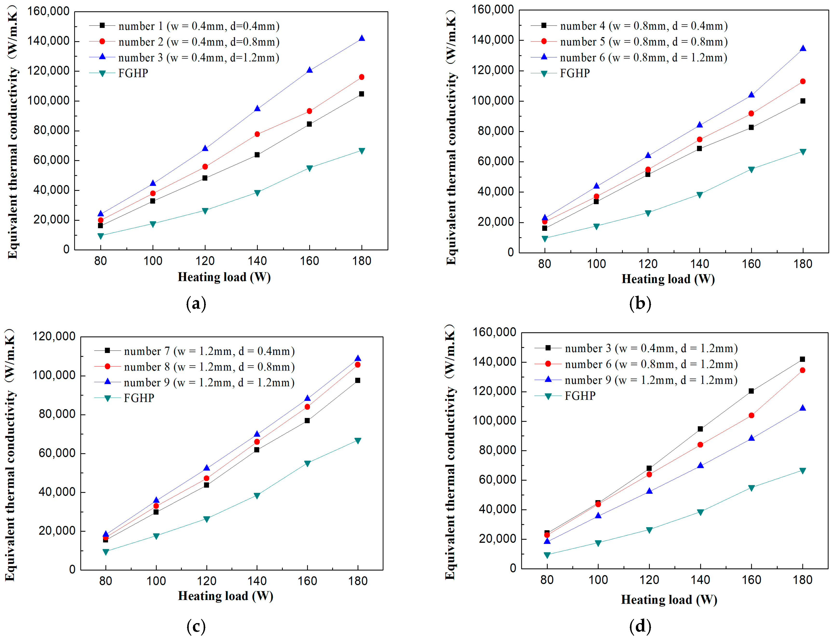
The equivalent thermal conductivity is a general indicator for heat transfer performance of a heat pipe. The equivalent thermal conductivity of the FGHP and FMGHPs with different micro-groove depths (0.4 mm, 0.8 mm and 1.2 mm) increases as the heating load increases, shown in Figure 6a (w = 0.4 mm), Figure 6b (w = 0.8 mm) and Figure 6c (w = 1.2 mm), respectively. When the heating load remains constant, the equivalent thermal conductivity of the FMGHPs increases with the increasing depth of the micro-grooves. FMGHPs 3, 6 and 9 have the highest equivalent thermal conductivity shown in Figure 6a–c, respectively. The FGHP without micro-grooves has the lowest equivalent thermal conductivity.
As shown in Figure 6d, FMGHPs 3, 6 and 9 have the same depth of 1.2 mm and different widths. The equivalent thermal conductivity of the FMGHPs increases with the decreasing width of the micro-groove at each heating load. For instance, at the heating load of 120 W, FMGHPs 3, 6 and 9 reach the equivalent thermal conductivity of 67,925 W/(m·K), 63,964 W/(m·K), and 52,363 W/(m·K), respectively. Their capacity for thermal conductivity is respectively 2.55, 2.41 and 1.97 times as that of the FGHP. The capacity for thermal conductivity of FMGHP 3 is the highest.
In summary, FMGHP 3 is selected from the nine FMGHPs with different micro-groove dimensions for the best performance in start-up and heat transfer aspects.
4.5. The Semi-Visualization Comparison of FMGHP and FGHP
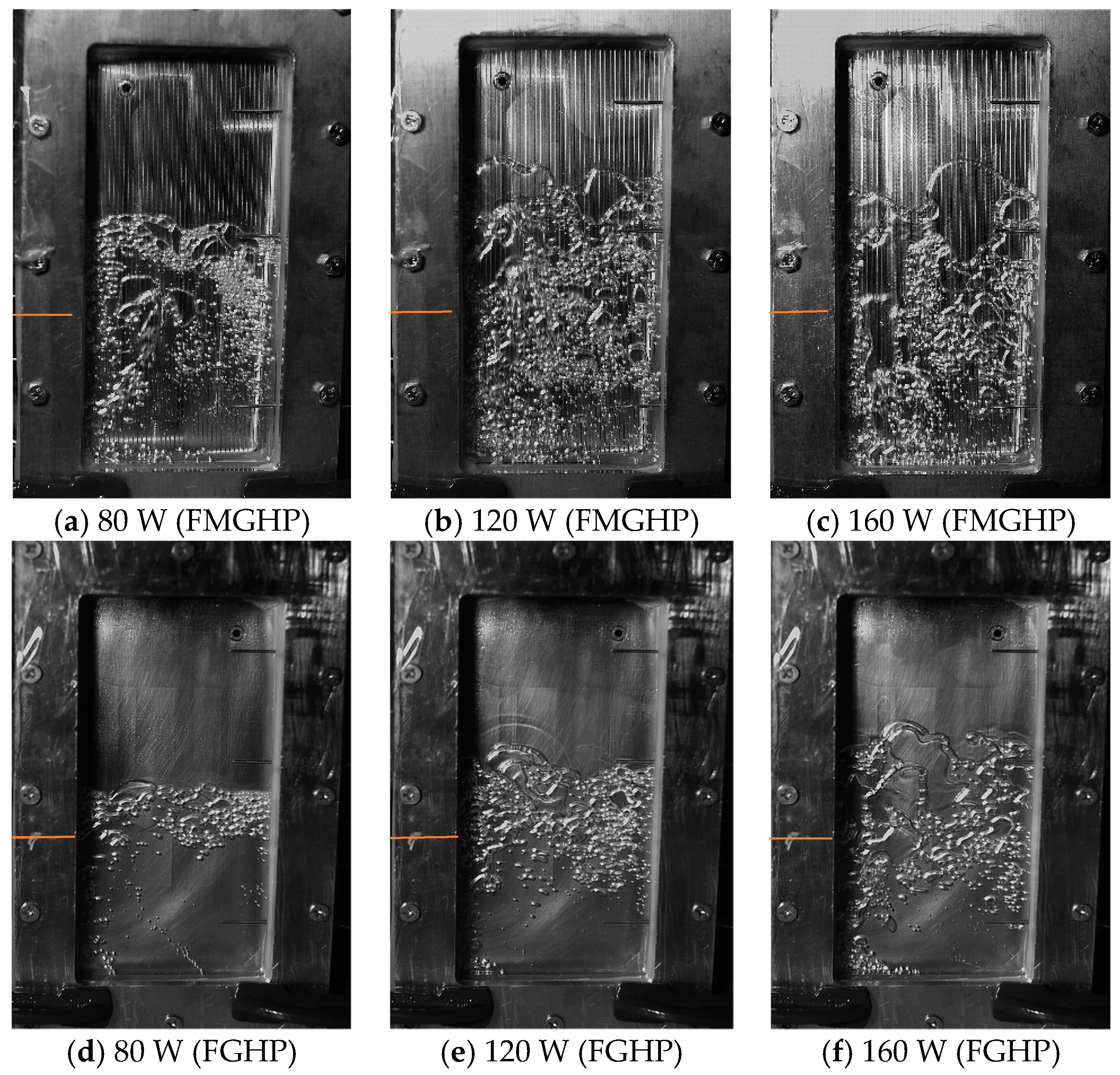
To clarify how the micro-grooves increase the thermal performance of FMGHPs, the liquid–vapor phase change heat transfer was observed by the visualized window. Taking comparability into account, the photos taken at the same time were chosen to obtain a reasonable observation. In Figure 7, the liquid–vapor two-phase behaviors at 300 s of FMGHP 3 (Figure 7a–c) and FGHP (Figure 7d–f) are compared at different heating loads (80 W, 120 W and 160 W).
When the heating load is 80 W in the FGHP at 300 s, a small amount of bubbles can be observed in Figure 7d. The relatively calm working fluid at the bottom zone of the evaporation section in the FGHP also proves the relatively weak liquid–vapor two-phase behavior. In comparison, the liquid–vapor two-phase behavior in FMGHP 3 shown in Figure 7a is relatively intensive. Larger and more bubbles can be seen in FMGHP 3 compared with the FGHP. Similarly, the coincident observations also exist in Figure 7b,e (120 W) and Figure 7c,f (160 W).
The gas–liquid two-phase behaviors begin by the formation of nucleation sites and the evolution of bubbles. The roughness of the wall creates conditions for the nucleation sites, the heterogeneous nucleation (which requires less nucleation energy) firstly appears on the micro-grooves and accidentally fabricated tiny cracks. Then, homogeneous nucleation is formed in the low-density region resulting from turbulence of the working liquid [21,24]. When the energy of the working fluid in the cavity accumulates with heating, the bubbles are generated from the nucleation sites. Moreover, the existence of micro-grooves which are embedded into the heated base contributes to the shorter distance from liquid to heat source and the larger heated surface. They are beneficial for the formation of nucleation sites and the evolution of bubbles.
With absorbing heat, the bubbles become larger and more are formed. They will rise, separating from the heated surface under multiple effects of surface and inertia force. In the evolution process of the bubbles, the strong interactional disturbance existing in the surrounding fluid and vapor prompts the merging and split of bubbles, which strengthens heat transfer ability. During the gas–liquid two-phase heat transfer process, evaporation and condensation coexist in the cavity of the heat pipe. Vapor releases latent heat in the cooling surface and condensed liquid flows back to the evaporation section. The micro-grooves play a positive role in strengthening heat transfer through exerting the capillary force and reducing the flow resistance in both the vapor and liquid sections.
5. Conclusions
Nine FMGHPs with different depths (0.4 mm, 0.8 mm, 1.2 mm) and widths (0.4 mm, 0.8 mm, 1.2 mm) were fabricated and experimented with at various heating loads (80–180 W). The findings can be summarized as follows:
- (1)
- With the increasing heating load, the start-up time, temperature difference and relative thermal resistance of FMGHPs show a declining trend and the equivalent thermal conductivity is enhanced.
- (2)
- The deeper and narrower micro-grooves show better thermal performance and the optimal rectangular micro-groove dimension among the selected options is determined as 1.2 mm (depth) × 0.4 mm (width) within the experimental range.
- (3)
- The start-up time, temperature difference, relative thermal resistance and equivalent thermal conductivity of FMGHPs are all better than that of the FGHP. The four indicators of FMGHP 3, which has the best thermal performance among the nine FMGHPs, are enhanced by 29%, 66%, 80% and 155%, respectively.
- (4)
- At the same heating load, the liquid–vapor two-phase behaviors in the FMGHP are more intensive. Larger and more bubbles can be observed in the cavity of the FMGHP compared with the observations of the FGHP.
Author Contributions
X.G. conceived the research. X.G., Q.Z. and Y.L. (Yamei Li) carried out the experiment, deduction, and calculation. Q.Z., Y.L. (Yamei Li), Y.L. (Yingfan Liu), S.L. and S.I. participated in the analysis of the data and writing of the initial manuscript. X.G. and Q.Z. revised the manuscript and adjusted the data presentation. All authors have read and approved the manuscript.
Funding
This research received no external funding.
Conflicts of Interest
The authors declare no conflict of interest.
References
- Yau, Y.H.; Ahmadzadehtalatapeh, M. A review on the application of horizontal heat pipe heat exchangers in air conditioning systems in the tropics. Appl. Therm. Eng. 2010, 30, 77–84. [Google Scholar] [CrossRef]
- Alijani, H.; Çetin, B.; Akkus, Y.; Dursunkaya, Z. Effect of design and operating parameters on the thermal performance of aluminum flat grooved heat pipes. Appl. Therm. Eng. 2018, 132, 174–187. [Google Scholar] [CrossRef]
- Lips, S.; Lefèvre, F.; Bonjour, J. Nucleate boiling in a flat grooved heat pipe. Int. J. Therm. Sci. 2009, 48, 1273–1278. [Google Scholar] [CrossRef]
- Li, Y.; He, H.F.; Zeng, Z.X. Evaporation and condensation heat transfer in a heat pipe with a sintered-grooved composite wick. Appl. Therm. Eng. 2013, 50, 342–351. [Google Scholar] [CrossRef]
- Yu, M.; Diallo, T.M.O.; Zhao, X.D.; Zhou, J.Z.; Du, Z.Y.; Ji, J.; Cheng, Y.D. Analytical study of impact of the wick’s fractal parameters on the heat transfer capacity of a novel micro-channel loop heat pipe. Energy 2018, 158, 746–759. [Google Scholar] [CrossRef]
- Tuckerman, D.B.; Pease, R.F.W. High performance heat sinking for VLSI. IEEE Electron Device Lett. 1981, 2, 126–129. [Google Scholar] [CrossRef]
- Wong, S.C.; Chen, C.W. Visualization and evaporator resistance measurement for a groove-wicked flat-plate heat pipe. Int. J. Heat Mass Transf. 2012, 55, 2229–2234. [Google Scholar] [CrossRef]
- Liu, X.D.; Chen, Y.P. Transient thermal performance analysis of micro heat pipes. Appl. Therm. Eng. 2013, 58, 585–593. [Google Scholar] [CrossRef]
- Suman, B.; Hoda, N. Effect of variations in thermophysical properties and design parameters on the performance of a V-shaped micro grooved heat pipe. Int. J. Heat Mass Transf. 2005, 48, 2090–2101. [Google Scholar] [CrossRef]
- Wu, H.Y.; Cheng, P. Visualization and measurements of periodic boiling in silicon microchannels. Int. J. Heat Mass Transf. 2003, 46, 2603–2614. [Google Scholar] [CrossRef]
- Jiao, A.J.; Ma, H.B.; Critser, J.K. Evaporation heat transfer characteristics of a grooved heat pipe with micro-trapezoidal grooves. Int. J. Heat Mass Transf. 2007, 50, 2905–2911. [Google Scholar] [CrossRef]
- Nagayama, G.; Gyotoku, S.; Tsuruta, T. Thermal performance of flat micro heat pipe with converging microchannels. Int. J. Heat Mass Transf. 2018, 122, 375–382. [Google Scholar] [CrossRef]
- Hopkins, R.; Faghri, A.; Khrustalev, D. Flat miniature heat pipes with micro capillary grooves. J. Heat Transf. 1999, 121, 102–109. [Google Scholar] [CrossRef]
- Do, K.H.; Kim, S.J.; Garimella, S.V. A mathematical model for analyzing the thermal characteristics of a flat micro heat pipe with a grooved wick. Int. J. Heat Mass Transf. 2008, 51, 4637–4650. [Google Scholar] [CrossRef] [Green Version]
- Saad, I.; Maalej, S.; Zaghdoudi, M.C. Combined effects of heat input power and filling fluid charge on the thermal performance of an electrohydrodynamic axially grooved flat miniature heat pipe. Appl. Therm. Eng. 2018, 134, 469–483. [Google Scholar] [CrossRef]
- Saad, I.; Maalej, S.; Zaghdoudi, M.C. Modeling of the EHD effects on hydrodynamics and heat transfer within a flat miniature heat pipe including axial capillary grooves. J. Electrostat. 2017, 85, 61–78. [Google Scholar] [CrossRef]
- Gillot, C.; Avenas, Y.; Cezac, N.; Poupon, G.; Schaeffer, C.; Fournier, E. Silicon heat pipes used as thermal spreaders. IEEE Trans. Compon. Packag. Technol. 2003, 26, 332–339. [Google Scholar] [CrossRef]
- Gou, X.; Li, Y.M.; Zhang, Q.Y.; Shah, I.A.; Zhao, D.; Liu, S.A.; Wang, Y.T.; Wang, E.Y.; Wu, J.X. A novel semi-visualizable experimental study of a plate gravity heat pipe at unsteady state. Energies 2017, 10, 1994. [Google Scholar]
- Kwon, G.H.; Kim, S.J. Experimental investigation on the thermal performance of a micro pulsating heat pipe with a dual-diameter channel. Int. J. Heat Mass Transf. 2015, 89, 817–828. [Google Scholar] [CrossRef]
- Yu, F.W.; Yu, C.; Cao, J.G.; Chen, Y.P. Experimental analysis of the evaporation regimes of an axially grooved heat pipe at small tilt angles. Int. J. Heat Mass Transf. 2018, 126, 334–341. [Google Scholar] [CrossRef]
- Ruckenstein, E.; Berim, G.O. Kinetics of heterogeneous nucleation on a rough surface: Nucleation of a liquid phase in nanocavities. J. Colloid Interface Sci. 2010, 351, 277–282. [Google Scholar] [CrossRef] [PubMed]
- Ji, X.B.; Xu, J.L.; Li, H.C. Huang, G.H. Switchable heat transfer mechanisms of nucleation and convection by wettability match of evaporator and condenser for heat pipes: Nanostructured surface effect. Nano Energy 2017, 38, 313–325. [Google Scholar] [CrossRef]
- Ruckenstein, E.; Djikaev, Y.S. Recent developments in the kinetic theory of nucleation. Adv. Colloid Interface Sci. 2005, 118, 51–72. [Google Scholar] [CrossRef] [PubMed]
- Baidakov, V.G.; Pankov, A.S. Nucleation in ethane–nitrogen solutions. I. Homogeneous nucleation. Int. J. Heat Mass Transf. 2015, 86, 930–935. [Google Scholar] [CrossRef]
Figure 1.
(a) A photo of a fabricated flat micro-grooved gravity heat pipe (FMGHP); (b) The A–A cross-section of the micro-grooves in a FMGHP (units: mm).
Figure 1.
(a) A photo of a fabricated flat micro-grooved gravity heat pipe (FMGHP); (b) The A–A cross-section of the micro-grooves in a FMGHP (units: mm).

Figure 2.
Experimental system of the semi-visualization FMGHP. AC = alternating current.

Figure 3.
The start-up time of the FMGHPs and the flat gravity heat pipe (FGHP) at different heating loads: (a) FMGHPs 1–3 and FGHP; (b) FMGHPs 4–6 and FGHP; (c) FMGHPs 7–9 and FGHP; (d) FMGHPs 3, 6, 9 and FGHP.
Figure 3.
The start-up time of the FMGHPs and the flat gravity heat pipe (FGHP) at different heating loads: (a) FMGHPs 1–3 and FGHP; (b) FMGHPs 4–6 and FGHP; (c) FMGHPs 7–9 and FGHP; (d) FMGHPs 3, 6, 9 and FGHP.

Figure 4.
The temperature difference of the FMGHPs and FGHP at different heating loads: (a) FMGHPs 1–3 and FGHP; (b) FMGHPs 4–6 and FGHP; (c) FMGHPs 7–9 and FGHP; (d) FMGHPs 3, 6, 9 and FGHP.
Figure 4.
The temperature difference of the FMGHPs and FGHP at different heating loads: (a) FMGHPs 1–3 and FGHP; (b) FMGHPs 4–6 and FGHP; (c) FMGHPs 7–9 and FGHP; (d) FMGHPs 3, 6, 9 and FGHP.

Figure 5.
The relative thermal resistance of the FMGHPs and FGHP at different heating loads: (a) FMGHPs 1–3 and FGHP; (b) FMGHPs 4–6 and FGHP; (c) FMGHPs 7–9 and FGHP; (d) FMGHPs 3, 6, 9 and FGHP.
Figure 5.
The relative thermal resistance of the FMGHPs and FGHP at different heating loads: (a) FMGHPs 1–3 and FGHP; (b) FMGHPs 4–6 and FGHP; (c) FMGHPs 7–9 and FGHP; (d) FMGHPs 3, 6, 9 and FGHP.

Figure 6.
The equivalent thermal conductivity of the FMGHPs and FGHP at different heating loads: (a) FMGHPs 1–3 and FGHP; (b) FMGHPs 4–6 and FGHP; (c) FMGHPs 7–9 and FGHP; (d) FMGHPs 3, 6, 9 and FGHP.
Figure 6.
The equivalent thermal conductivity of the FMGHPs and FGHP at different heating loads: (a) FMGHPs 1–3 and FGHP; (b) FMGHPs 4–6 and FGHP; (c) FMGHPs 7–9 and FGHP; (d) FMGHPs 3, 6, 9 and FGHP.

Figure 7.
The liquid–vapor two-phase behaviors at 300 s of FMGHP 3 (a–c) and the FGHP (d–f) at different heating loads. Note: the initial liquid level is marked with the red line.
Figure 7.
The liquid–vapor two-phase behaviors at 300 s of FMGHP 3 (a–c) and the FGHP (d–f) at different heating loads. Note: the initial liquid level is marked with the red line.


Table 1.
The nine kinds of dimensions of rectangular micro-grooves.
| FMGHP Number | Depth (d) | Width (w) | Micro-Groove Length | Micro-groove Number |
|---|---|---|---|---|
| (mm) | (mm) | (mm) | ||
| 1 | 0.4 | 0.4 | 200 | 40 |
| 2 | 0.8 | |||
| 3 | 1.2 | |||
| 4 | 0.4 | 0.8 | ||
| 5 | 0.8 | |||
| 6 | 1.2 | |||
| 7 | 0.4 | 1.2 | ||
| 8 | 0.8 | |||
| 9 | 1.2 |
© 2018 by the authors. Licensee MDPI, Basel, Switzerland. This article is an open access article distributed under the terms and conditions of the Creative Commons Attribution (CC BY) license (http://creativecommons.org/licenses/by/4.0/).
Share and Cite
MDPI and ACS Style
Gou, X.; Zhang, Q.; Li, Y.; Liu, Y.; Liu, S.; Iram, S. Experimental Research on the Thermal Performance and Semi-Visualization of Rectangular Flat Micro-Grooved Gravity Heat Pipes. Energies 2018, 11, 2480. https://doi.org/10.3390/en11092480
AMA Style
Gou X, Zhang Q, Li Y, Liu Y, Liu S, Iram S. Experimental Research on the Thermal Performance and Semi-Visualization of Rectangular Flat Micro-Grooved Gravity Heat Pipes. Energies. 2018; 11(9):2480. https://doi.org/10.3390/en11092480
Chicago/Turabian StyleGou, Xiang, Qiyan Zhang, Yamei Li, Yingfan Liu, Shian Liu, and Saima Iram. 2018. "Experimental Research on the Thermal Performance and Semi-Visualization of Rectangular Flat Micro-Grooved Gravity Heat Pipes" Energies 11, no. 9: 2480. https://doi.org/10.3390/en11092480
Note that from the first issue of 2016, this journal uses article numbers instead of page numbers. See further details here.