Article

Leveraging Hybrid Filter for Improving Quasi-Type-1 Phase Locked Loop Targeting Fast Transient Response

1
School of Electrical Engineering, Shenyang University of Technology, Shenyang 110870, China
2
Liaoning Province Electric Power Company, Shenyang 110006, China
*
Author to whom correspondence should be addressed.
Energies 2018, 11(9), 2472; https://doi.org/10.3390/en11092472
Submission received: 4 September 2018 / Revised: 13 September 2018 / Accepted: 16 September 2018 / Published: 17 September 2018
(This article belongs to the Special Issue Power Electronics in Renewable Energy Systems)

Abstract

:
In renewable energy generation applications, phase locked loop (PLL) is one of the most popular grid synchronization technique. The main objective of PLL is to rapidly and precisely extract phase and frequency especially when the grid voltage is under non-ideal conditions. This motivates the recent development of moving average filters (MAFs) based PLL in a quasi-type-1 system (i.e., QT1-PLL). Despite its success in certain applications, the transient response is still unsatisfactory, mainly due to the fact that the time delay caused by MAFs is still large. This has significantly limited the utilization of QT1-PLL, according to common grid codes such as German and Spanish grid codes. This challenge has been tackled in this paper. The basic idea is to develop a new hybrid filtering stage, consisting of adaptive notch filters (ANFs) and MAFs, arranged at the inner loop of QT1-PLL. Such an idea can greatly improve the transient response of QT1-PLL, owing to the fact that ANFs are utilized to remove the fundamental frequency negative voltage sequence (FFNS) component while other dominant harmonics can be removed by MAFs with a small time delay. By applying the proposed technique, the settling time is reduced to less than one cycle of grid frequency without any degradation in filtering capability. Moreover, the proposed PLL can be easily expanded to handle dc offset rejection. The effectiveness is validated by comprehensive experiments.

1. Introduction

With the development of renewable energy system, PLL is widely used in most of grid-connected power converter applications owing to its simple structure [1]. Synchronous-reference-frame based PLL (SRF-PLL) is a standard PLL in three-phase grid connected applications, as shown in Figure 1. Since the open-loop transfer function of its model has two poles at the origin, SRF-PLL can be treated as a type-2 PLL (a type-N system has N poles at origin). When grid voltages are unpolluted, SRF-PLL can provide zero phase-error under phase jump and frequency deviation [2,3]. However, its phase-tracking performance degrades under non-ideal grid conditions owing to the existence of disturbances voltage components such as FFNS component and harmonics [4]. This motivates the work [5] to integrate low-pass filters into SRF-PLL, together with moving average filter (MAF) or delay signal cancellation (DSC) operator, to attenuate disturbances. Despite its success in completely removing harmonics, it incurs significant degradation of the dynamic performance. This has significantly limited its applications due to the restriction of common grid codes such as German and Spanish grid codes [6,7].
In recent years, many PLLs were developed to make improvements in phase tracking performance. Some type-2 PLLs, such as multiple complex-coefficient-filter-based PLL (MCCF-PLL) [8], dual second-order generalized integrator based PLL (DSOGI-PLL) [9] and multiple reference frame based PLL (MRF-PLL) [10], provide a higher bandwidth by using hybrid filtering but high order harmonics cannot be totally removed. Although some MAF and DSC based hybrid filtering stage can solve this problem, the time delay induced by MAF or DSC is large. In Reference [11], a differential MAF-PLL (DAMF-PLL) was proposed. Although the window length (Tω) of its MAF is narrowed, the settling time is still over one cycle, which can hardly satisfy the requirements in some grid code [12,13]. Recently, a novel PLL structure with rapid transient response was proposed in Reference [14], which is named quasi-type-1 PLL (QT1-PLL). Some advanced PLLs also improve their dynamic performance by using QT1 structure. But the filtering capability of these existing quasi-type-1 structure based PLLs is still unsatisfactory. A brief literature review related to some advanced PLLs mentioned above is given in Section 2.
To tackle the above technical challenge, this paper develops a new hybrid filtering stage, consisting of adaptive notch filters (ANFs) and MAFs, arranged at the inner loop of QT1-PLL. Such an idea can reduce the settling time of QT1-PLL, because ANFs are employed to eliminate the FFNS while other dominant harmonics can be removed by MAFs with a narrowed window length. By using the proposed method, the convergence time is reduced to a short time within one grid period without any degradation in filtering capability. The propose method is motivated from [11]. Moreover, compared with author’s other two papers [15,16], besides the main difference in filtering technique, this paper also studies the digital implementation of the proposed method in more detail. The computational burden is evaluated and the adaptive implementation of MAFs is also discussed. On the contrary, lacking this part of the discussion [15,16], it is difficult to implement in a practical embedded system.
Our contribution is as follows.
  • A novel hybrid filtering stage with narrowed Tω of MAFs is proposed, which can remove dominant disturbances completely without degrading the dynamic performance.
  • In conventional QT1-PLL, only phase margin (PM) is considered in design procedure [14]. In this paper, the settling times under two adverse grid conditions are directly taken into account in design guidelines. In addition, PM does not decrease yet.
  • To validate the effectiveness of the proposed method, a comprehensive experimental study is performed which considers many cases such as phase and frequency change, voltage sag and harmonic polluted grid voltages. The results show that the transient behavior lasts for nearly one grid period. Compared with QT1-PLL, the settling time is reduced by nearly 40%, which makes it fulfill the stringent transient response requirement in most grid standard [6,7].
  • As a byproduct, the proposed PLL can also handle dc offset by using two more ANFs. It is examined under dc offset injection condition. This advantage is confirmed by comparative experiments.
Literature review is presented in Section 2. The suggested hybrid filtering technique and PLL is introduced and analyzed in detailed in Section 3. The mathematical modeling of the proposed PLL is derived in Section 4. Section 4 also provides parameter design guidelines and evaluates the stability of open-loop system. In Section 5, comparative experiments are implemented to validate performance of the proposed method.

2. Literature Review

To achieve a satisfactory performance under adverse conditions, many advanced PLLs were suggested recently. Almost all these PLLs evolved from SRF-PLL. According to control structure, a general classification of some typical advanced PLLs is depicted in Figure 2. All of these PLLs, except MAF-PLL and QT1-PLL, use hybrid filter based on low pass filter (LPF) or MAF.
To achieve a better performance, LPF-based hybrid filtering stage is employed in many advanced PLLs, such as MCCF-PLL [8], DSOGI-PLL [9] and MRF-PLL [10]. The hybrid filtering stage, which are usually arranged at the front of Park transformation, can be divided into two parts. One part is responsible for eliminating FFNS, which can be considered as a notch filter. Another, act as a LPF, is used to reject other dominant harmonics. Although the bandwidth of these PLLs open-loop system becomes higher, high order harmonics still remain owing to the usage of LPFs. MAFs and DSCs can be adopted to overcome this disadvantage. They can act as ideal filters to remove harmonic disturbance completely. Nevertheless, the transient behavior is slowed down by time delays of MAFs and DSCs [17]. MAF-based hybrid filtering technique is also developed in recent years. It makes MAF can fulfill disturbances rejection requirement with a narrowed Tω. In Reference [11], DMAF-PLL is successful in reducing Tω. However, a big deviation of frequency estimation occurs under a phase step change condition owing to the differential proportional component, which may bring about an unexpected tripping operation in some power generation applications [18,19].
Another approach to improve PLL’s transient performance is to reduce the type of a PLL system. In Reference [20], a hybrid type-1/type-2 PLL with a so-called reconstructor unit was proposed. This PLL performs as a type-1 PLL under normal grid condition. When grid frequency is off-nominal, the reconstructor is activated to make the system behave as a type-2 system. Owing to this variable-structure, this hybrid type1/2 PLL provides a fast response. Motivated by [20], QT1-PLL was proposed in Reference [14]. The block scheme of QT1-PLL is depicted in Figure 3. Unlike type-2 PLL structure, QT1-PLL has a feed-forward control path. It makes QT1-PLL similar to type-1 PLL structure. However, from the control viewpoint, it is actually a type-2 system. Compared with MAF-PLL, it not only provides almost same filtering capability but also achieves less settling time under a frequency step change condition. Although the disturbance rejection capability is not better than that of MAF-PLL when grid frequency drifts, it can be simply solved by making the MAFs’ window length adaptive adjust with grid frequency. To expand its application conditions, a hybrid filter based PLL named HPLL was proposed in Reference [21]. Its filtering stage consists of DSCs and MAFs. With the employment of DSCs, HPLL offers a dc-offset filtering capability for QT1-PLL. The disadvantage of QT1-PLL and HPLL is the large delay in MAFs and DSCs. It is a common defect of many MAF/DSC based PLLs. In Reference [22], a novel-type-1 PLL (NT1-PLL) implemented in QT1-PLL structure is proposed. Its filtering stage act as same as that in MCCF-PLL. Although NT1-PLL provides a much better dynamic performance, the utilization of LPF makes its filtering stage unable to completely remove high order harmonics disturbance. Consequently, phase-error of NT1-PLL still exists under distorted grid conditions.
A performance comparison between some of typical PLLs mentioned above is listed in Table 1. As discussed above, the transient behaviors of most of type-2 PLLs and MAF/DSC based PLLs are slow. The quasi-type-1 structure shows its advantage in dynamic performance.

3. The Hybrid Filtering Stage and Proposed PLL

To reduce the settling time of PLLs as small as possible, a hybrid cascaded filtering stage is incorporated into QT1-PLL structure. The window length of MAFs is narrowed. The proposed PLL enhances the advantage of QT1-PLL in dynamic performance.

3.1. The Proposed PLL

The scheme of QT1-PLL structure is depicted in Figure 3. vabc is three-phase grid voltage, vd,q is d,q-axis voltage of vabc. v ¯ d and v ¯ q are dc components in vd and vq. ωff is the nominal frequency value of fundamental frequency positive voltage sequence (FFPS). ∆ω denotes the deviation of input frequency from ωff. The estimated values of FFPS’s frequency and phase is represented by ω ^ and θ ^ 1 + .
In three-phase grid applications, unbalanced grid voltages can be decomposed into FFPS, FFNS and non-triplen odd harmonic sequences [22]. Since these dominant disturbances in αβ-frame turn to be even harmonics in dq-frame after using Park transformation [23,24], frequency of the lowest order harmonic which is FFNS component turns to be −100 Hz. FFPS turns to be DC components. Thus, Tω of MAF is selected to be half a cycle (0.01 s for 50 Hz grid) in QT1-PLL. Table 2 lists the dominant component in the most practical conditions [25]. Since these components represent grid voltage vectors, some of their signs are negative to represent that the negative sequence vectors rotate in counterclockwise direction.
Figure 4 illustrates the block scheme of the proposed PLL. ANFs are embedded into QT1-PLL. All disturbances are filtered by the proposed hybrid filtering stage in dq-frame. ANFs are utilized to eliminate −100Hz FFNS. The rest of harmonics (±300 Hz, ±600 Hz, etc.) are removed by MAFs. Since the lowest harmonic order turns to be ±6 (±300 Hz components) rather than −2 (−100 Hz component) in QT1-PLL, Tω of MAF is reduced to be 0.0033 s (1/6 grid cycle).

3.2. Hybrid Cascaded Filtering Stage

As introduced above, the proposed filtering stage is composed of ANFs and MAFs. It can provide an ideal filtering capability and improve the dynamic performance. To achieve this goal, the parameters in the hybrid filtering stage needs to be properly designed in this part.
Since Tω of MAFs is already set to be 0.0033 s as mentioned above, ANF is the only component to be designed, which is written as
ANF ( s ) = s 2 + ( 2 ω ^ ) 2 s 2 + 2 ω ^ ξ s + ( 2 ω ^ ) 2
where ξ is the damping factor and ω ^ is the estimation of grid frequency. For a 50 Hz power system under normal condition, ω ^ equals to 2π50 rad/s. Figure 5 shows the bode plot of ANF part of filtering stage with different values of ξ. It is observed that FFNS (−100 Hz) component is eliminated and FFPS (0 Hz) remains without any change in magnitude or phase. ξ is determined by step response simulations of ANF(s). The results are depicted in Figure 6. A trade-off is made between the transient response and peak deviation. Therefore, ξ is selected to be 0.7. Since ANF is an adaptive filter and its notch frequency depends on the ω ^ , the frequency adaptive structure of ANF is necessary and depicted in Figure 7.
As studied in many literature [26,27], the MAF can be expressed as
MAF ( s ) = 1 e T ω s T ω s
Then, the proposed hybrid filtering stage can be expressed as
H ( s ) = ANF ( s ) MAF ( s ) = s 2 + ( 2 ω ^ ) 2 s 2 + 2 ω ^ ξ s + ( 2 ω ^ ) 2 1 e T ω s T ω s
where ξ = 0.7 and Tω = 0.0033 s.
Figure 8 depicts the frequency characteristic of H(s). Observing Figure 8, H(s) has a unity gain and zero phase shift at 0 Hz. It means H(s) has no impact on FFPS in dq-frame. H(s) also provides zero gain at frequencies of the dominant disturbances (−100 Hz, ±300 Hz, ±600 Hz, etc.). The dominant disturbances listed in Table 2 can be totally removed by the proposed hybrid filtering stage.

3.3. Proposed Hybrid Filter with DC Offset Rejection Capability

In some cases, with DC injection from power converters or A/D conversion, DC offset may present at the input of PLL. If DC offset rejection is required and necessary in some applications, an ANF designed to remove DC offset can be included in the inner loop of the proposed method. The DC offset occurs as −50 Hz voltage sequence vector in dq-frame. Hence, the ANF used for DC offset removal is expressed as
ANF dc ( s ) = s 2 + ( ω ^ ) 2 s 2 + 2 ω ^ ξ s + ( ω ^ ) 2
The whole hybrid filtering stage with ANFdc can be written as
H dc ( s ) = ANF ( s ) ANF dc ( s ) MAF ( s ) = s 2 + ( 2 ω ^ ) 2 s 2 + 2 ω ^ ξ s + ( 2 ω ^ ) 2 s 2 + ( ω ^ ) 2 s 2 + 2 ω ^ ξ s + ( ω ^ ) 2 1 e T ω s T ω s
where ξ is also 0.7. The frequency response of Hdc(s) is illustrated in Figure 9. It shows that Hdc(s) can completely remove −50 Hz voltage sequence caused by dc offset and other disturbance components listed in Table 2.

4. Small-Signal Modeling and Design Procedure

Based on a small-signal model, parameters design procedures are suggested in Section 4. The transient response under two abnormal conditions are the key factors concerned in the procedure. The stability analysis is also presented in this section.

4.1. Small-Signal Model

Since the filtering stage of QT1-PLL and the proposed PLL is the major difference, the model of the proposed method can be simply obtained from that of QT1-PLL (as shown in Figure 10) [14], by substituting H(s) for MAF. The small-signal model of the proposed PLL is shown in Figure 11. D(s) represents all disturbances. To be brief, the detailed derivation of the model is not presented. A simulation is implemented in Section 3 to assess the modeling accuracy.

4.2. Parameter Design Guidelines

As already mentioned above, the parameters in the proposed hybrid filter, Tω and ξ are already selected to be 0.0033 s and 0.7, respectively. Therefore, only k is left to be designed.
Applying block diagram algebra to Figure 11, a simplified small-signal model is achieved in Figure 12, which is a typical close-loop system. Its open-loop transfer function is
G ol ( s ) = θ ^ 1 + ( s ) θ 1 + ( s ) θ ^ 1 + ( s ) = ( ANF ( s ) MAF ( s ) 1 ANF ( s ) MAF ( s ) ) ( s + k s )
The phase tracking error transfer function is
G e ( s ) = θ e ( s ) θ 1 + ( s ) = θ 1 + ( s ) θ ^ 1 + ( s ) θ 1 + ( s ) = 1 1 + G ol ( s )
where θe(s) represents phase error. In response to a phase jump (Δθ), phase-error can be expressed in s-domain as
Θ e Δ θ ( s ) = Δ θ s G e ( s )
In response to a frequency jump (Δω), phase-error is
Θ e Δ θ ( s ) = Δ ω s 2 G e ( s )
To provide a rapid transient response under both phase and frequency jump conditions, the settling time is examined by applying inverse Laplace transform to phase-error. As a function of k, the variations of 2% settling time for phase jump (solid line) and frequency jump (dashed line) are depicted in Figure 13. It is obvious that choosing k to be 150 is an optimal value considering both conditions.
Since all the parameters are given, the open-loop bode diagram is depicted in Figure 14. PM of the proposed PLL and QT1-PLL is 45.3 degree and 44.8 degree, respectively. It is enough to ensure their stability. Compared with QT1-PLL, the crossover frequency of the suggested PLL is bigger. It also illustrates that all dominant disturbance components listed in Table 2 can be eliminated, completely.
When dc offset exists in grid voltages and is required to be eliminated in some applications, Hdc(s) is recommended for this task, which is proposed in the previous section. The design procedure is similar to the design guidelines mentioned above. For the sake of brevity, it is not presented here. According to Figure 15, k can be chosen to be 76.5. The corresponding open-loop bode diagram is depicted in Figure 16. DC component (50 Hz component in dq-frame) is removed by the proposed method. The phase margin is 31 degrees at 32.5 Hz, which illustrates that the system is stable. Compared with QT1-PLL, the bandwidth is bigger.

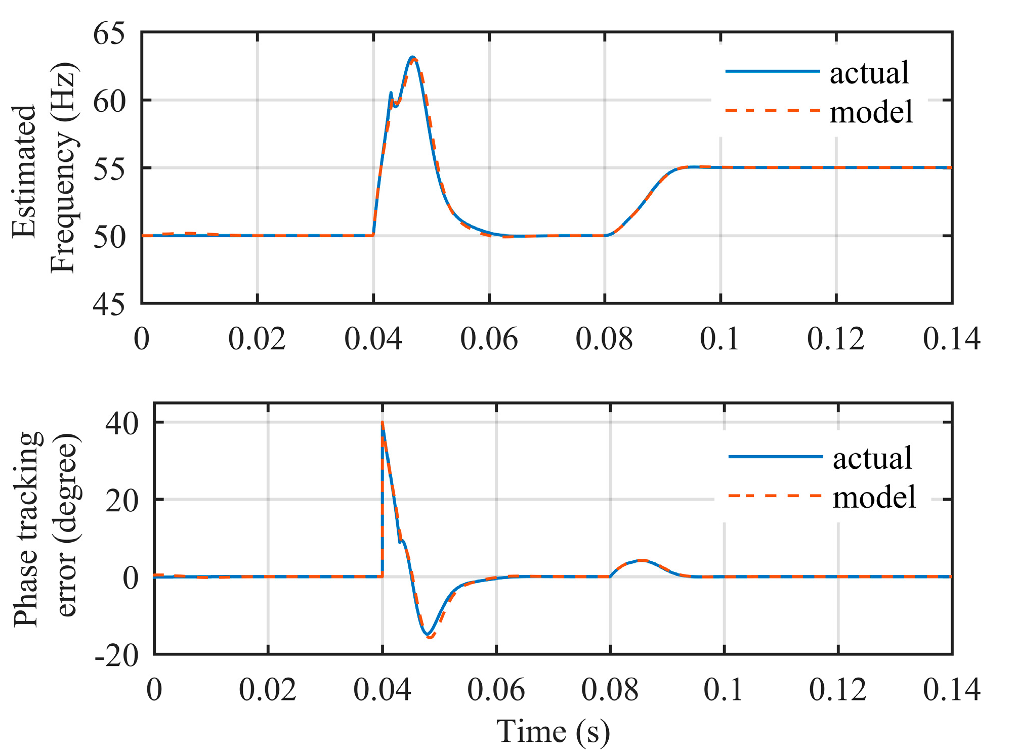
4.3. Assessment of Small-Signal Model

To assess the accuracy of the small-signal model, a simulation is carried out under phase jump (+40°) and frequency step change (+5 Hz) simulations. As depicted in Figure 17, the model can precisely predict the transient response of the proposed PLL. For brevity, the assessment of the proposed method with DC rejection capability is not presented.

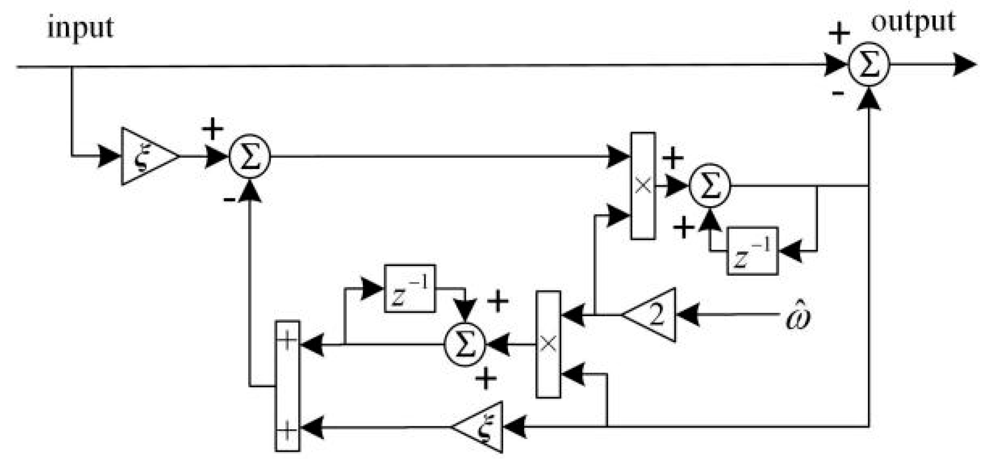
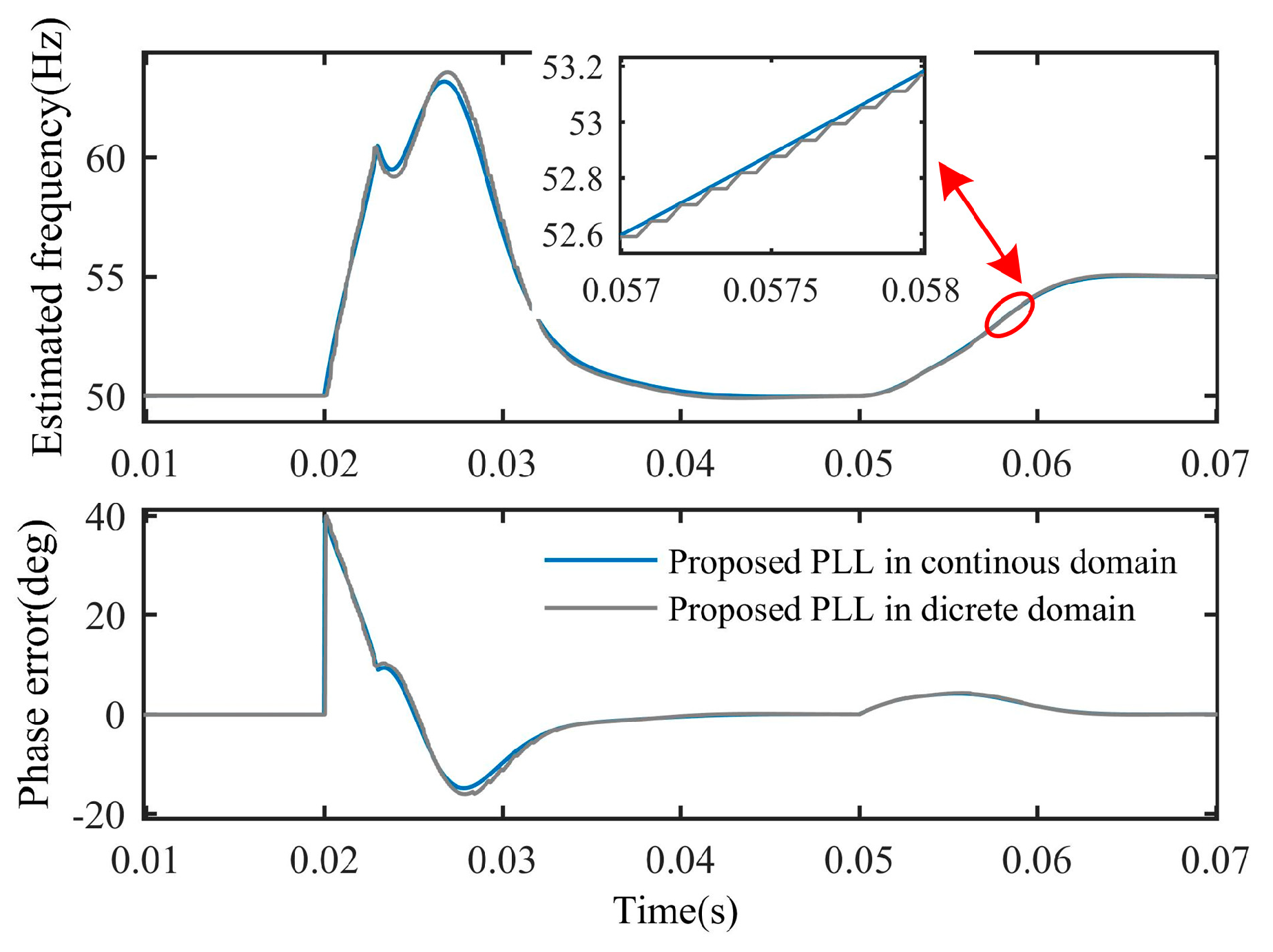
4.4. Digital Implementation

The proposed PLL is designed in the continuous-time domain. However, a discrete-time realization is required in practice. The main difference between the proposed method and QT1-PLL is ANFs. To discretize ANFs, Back Euler method is used to approximate the integrals in ANF as follow,
1 s T S 1 z 1
Figure 18 shows the discrete-time realization of ANF. It can be observed that ANF requires five multipliers, three adders, two subtractors and two stored samples. To assess the computational burden, Table 3 lists the math operator required in the hybrid filtering stage. Although the proposed PLL require a little more math operation, it takes much less storage space than QT1-PLL.
The impact of frequency variation of MAF is another thing need to be noticed. If the grid frequency drifts away from its nominal value, MAF with a fixed window length cannot completely remove harmonics. Hence, MAFs are frequency-adaptive in the proposed PLL. They can change their window length based on the online estimation of grid frequency. Several methods can be implemented to realize a frequency-adaptive MAF. A simplest form to adjust the window length of MAF is to round-down or round-up Tω/Ts to the nearest integer. However, this method introduces discretization error. To reduce this error, linear interpolation method is used in this paper, which increases computational burden. MAFs used in QT1-PLL, DMAF-PLL are also adaptive in this paper. The detailed linear interpolation method and frequency MAF implementation can be found in References [20,28].
Figure 19 illustrates the discretization effect of the proposed PLL in simulation. The sample time used in discretization is 10 kHz. As depicted in Figure 19, the dynamic behaviors in continuous domain and discrete domain are almost same.

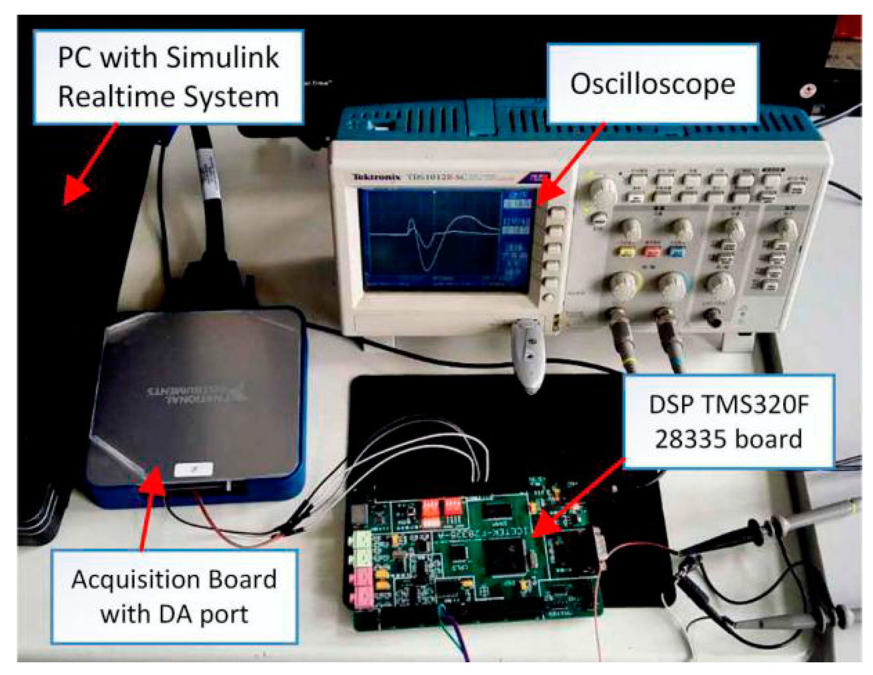
5. Experimental Results
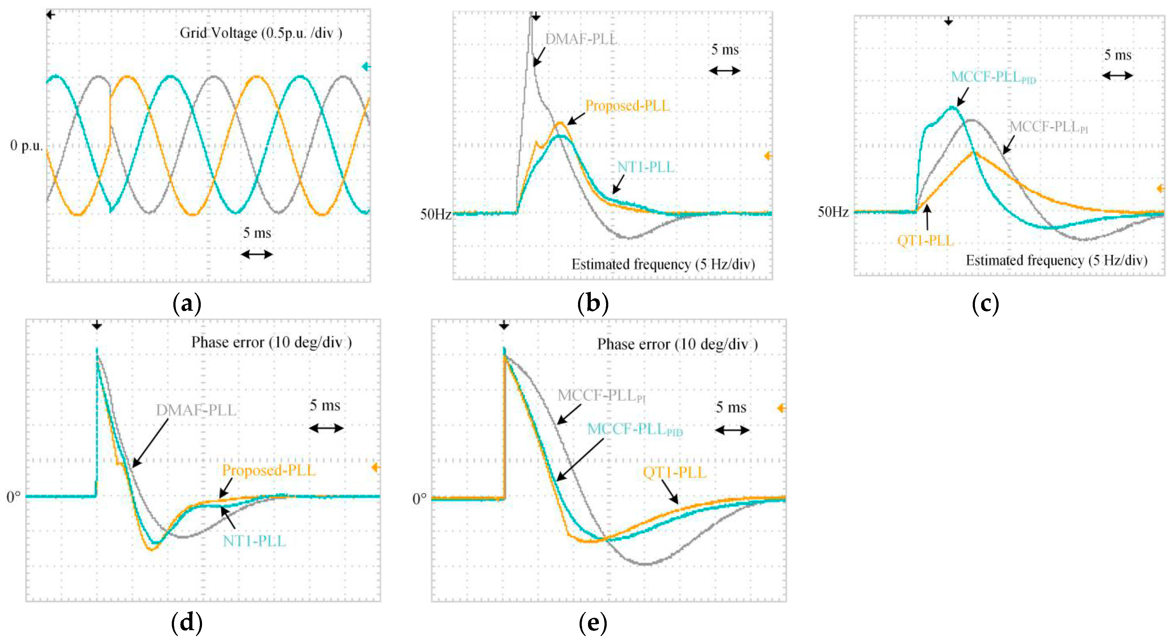
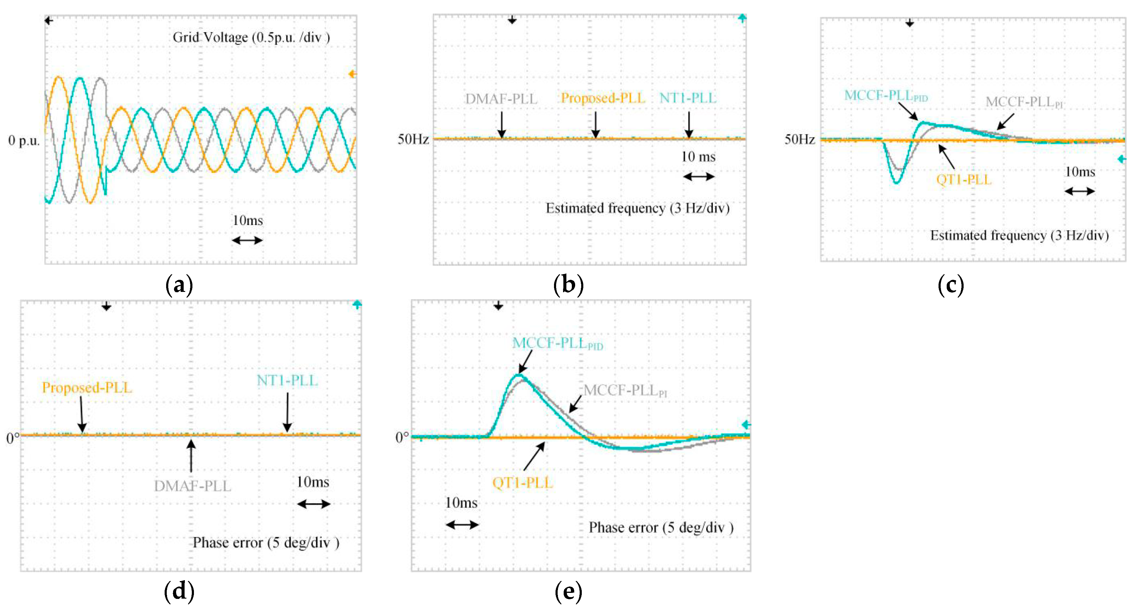
To validate performance, experimental results are provided and analyzed here. The proposed PLL is realized in a digital signal processor. The sampling frequency is 10 kHz. A programmable arbitrary waveform generator, which is built by PC and acquisition board, is utilized to obtain 50 Hz three-phase voltages signals. DSP board exports the estimated frequency and phase-error through DA conversion circuit. All waveforms are captured by oscilloscope. Figure 20 shows the experimental setup.
For comparison, several advanced PLLs are also implemented in the experiments. QT1-PLL [14] and Novel Type-1 PLL (NT1-PLL) [22] are carried out since they both have quasi-type-1 structure. DMAF-PLL [11], MCCF-PLLPID [29], MCCF-PLLPI [8] are implemented since their filtering stages are also hybrid. These PLLs were proposed in recent three years. Their parameters used in experiment can be found in the literature mentioned above.

5.1. Phase Jump

All PLLs are examined under a +40° phase jump voltages condition. Observing the waveforms in Figure 21, the settling time of the proposed PLL is shortest. Its 2% settling time is about 0.9 grid period. NT1-PLL and DMAF-PLL also provide satisfactory dynamic performance. However, an over 30 Hz overshoot occurs in the estimated frequency of DMAF-PLL. It may violate some restriction in some grid standard [30]. Unexpected tripping operation may be triggered [31]. The settling time of other three PLLs is almost 35 ms. According to the requirement in transient response mentioned in many grid standard [6,7,12,13], the estimation of voltage parameters need to be finished within 25 ms. Hence, QT1-PLL, MCCF-PLLPID, MCCF-PLLPI are not eligible under such condition.

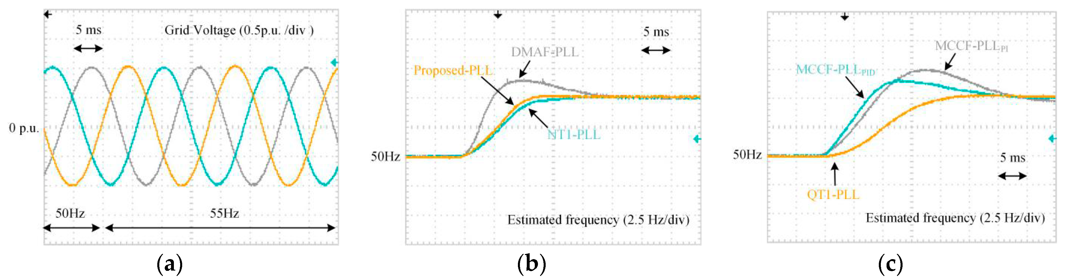
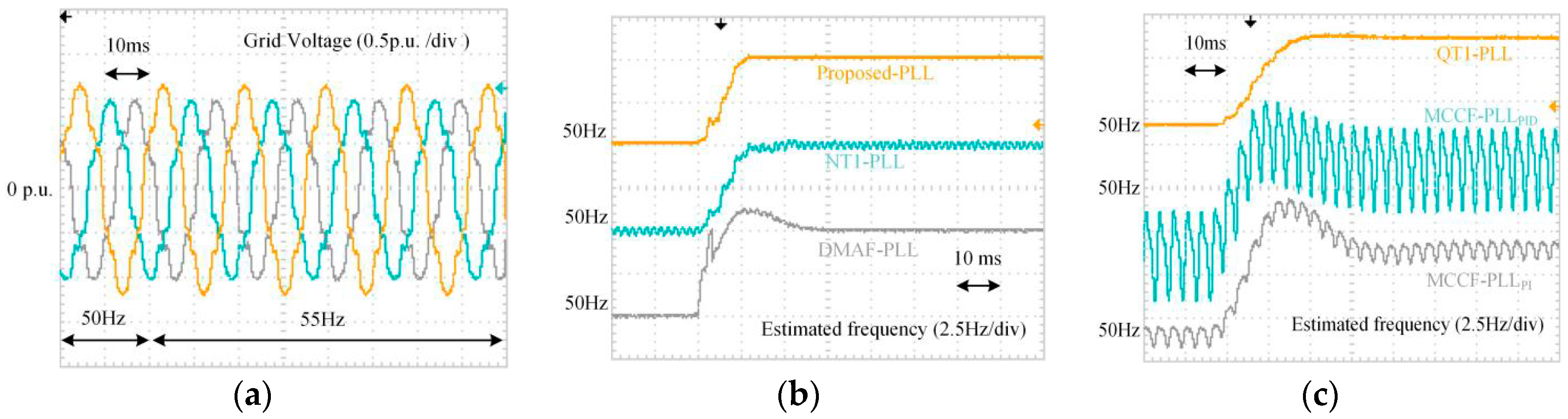
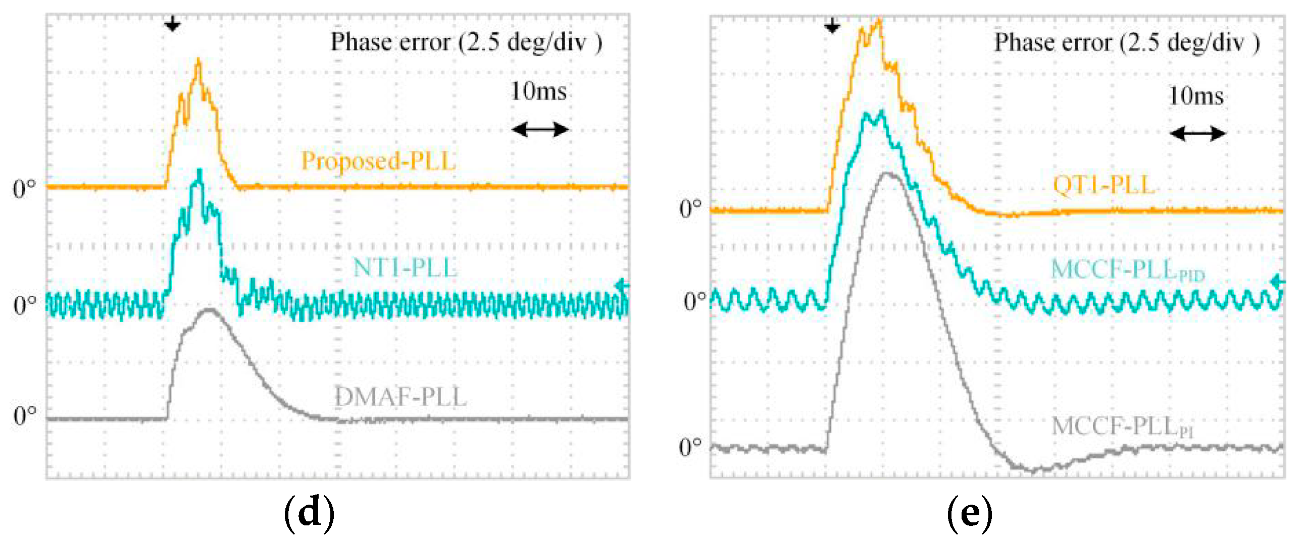
5.2. Frequency Step Change

Figure 22 illustrates the waveforms under a frequency step change grid condition. As shown, the proposed PLL and NT1-PLL track the grid frequency in 14 ms and 17 ms, respectively. Furthermore, within 15 ms, the phase-error of the suggested PLL converges to zero. The frequency tracking transient response of QT1-PLL and DMAF-PLL are also acceptable. But, the settling time of MCCF-PLLPID, MCCF-PLLPI is over 30 ms, which cannot meet the requirement of the grid code. On the other hand, DMAF-PLL, MCCF-PLLPID, MCCF-PLLPI have over +1.5 Hz peak frequency deviation. On the contrary, other three PLLs have no frequency overshoot.

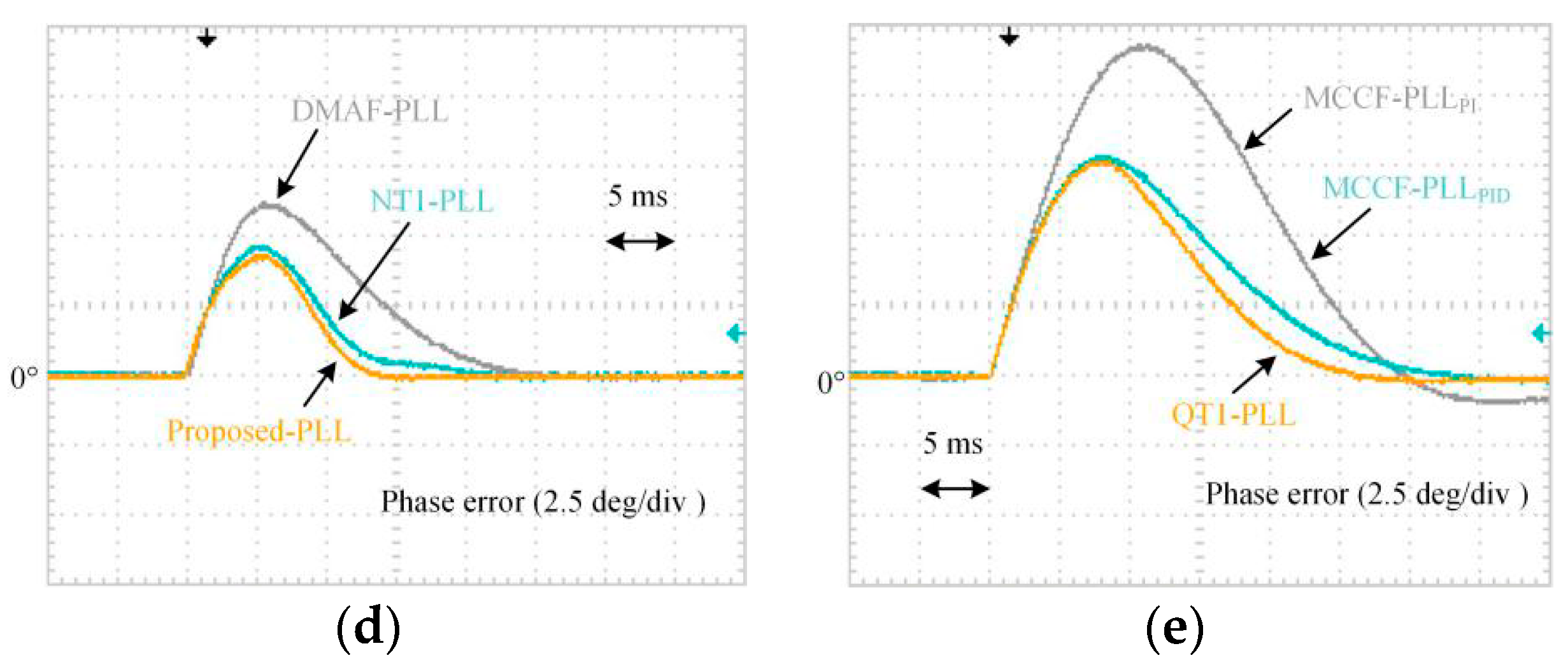
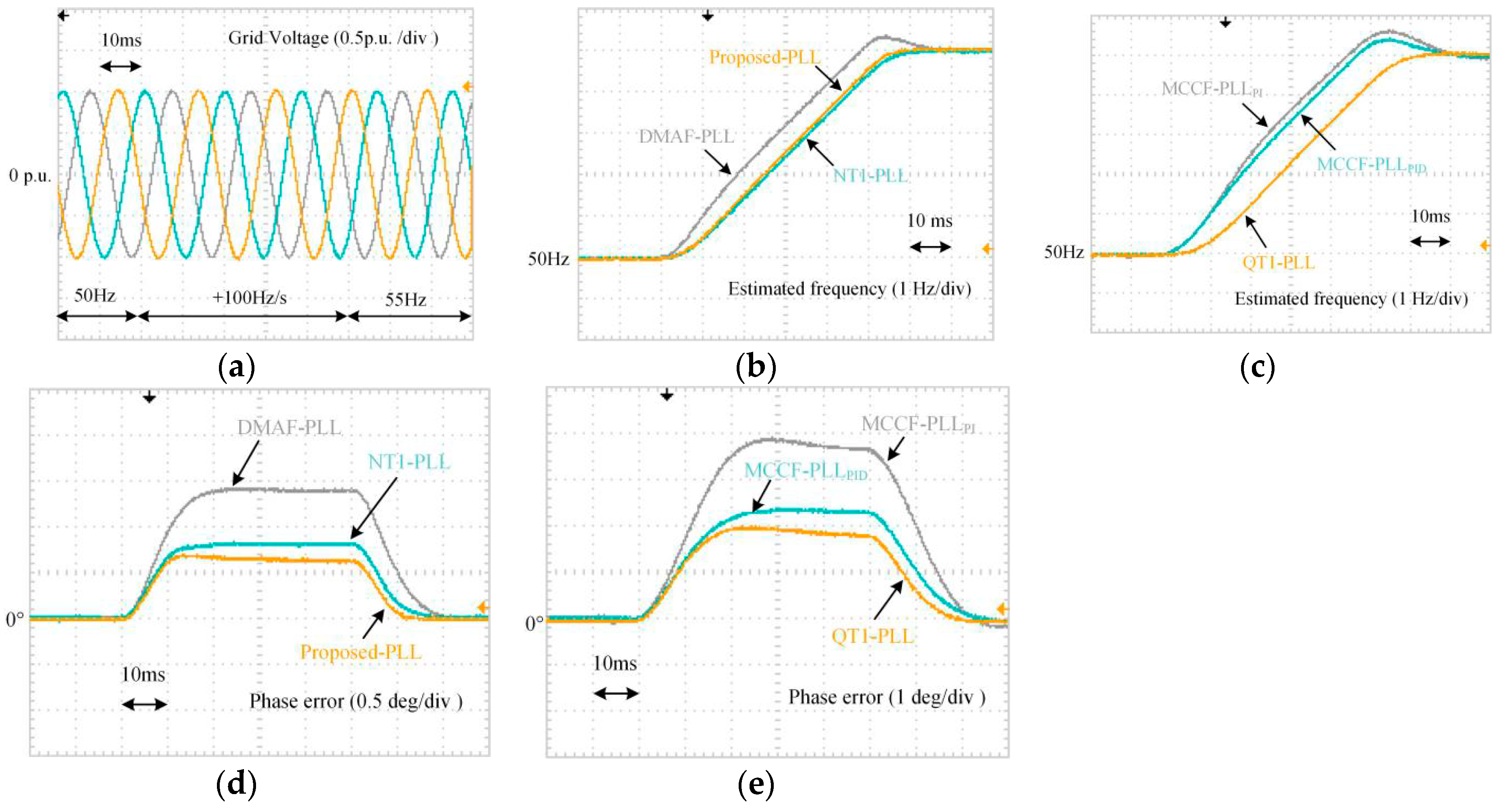
5.3. Frequency Ramp Change
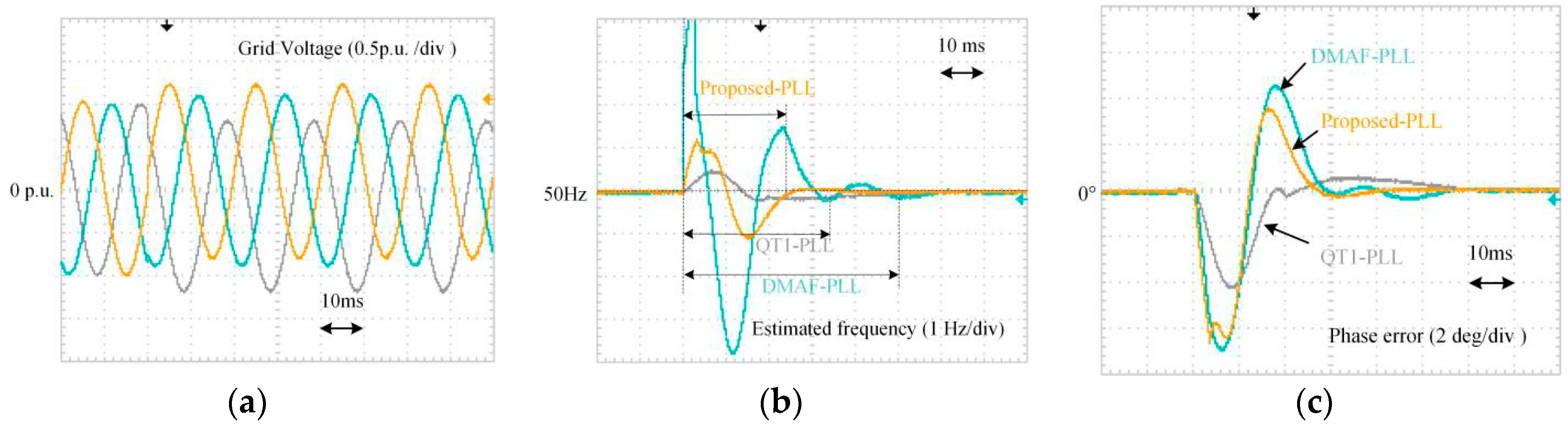
To evaluate the effectiveness during frequency ramp change, voltage frequency is increased from 50 Hz to 55 Hz in 50 ms. The ramp rising rate is +100 Hz/s. As depicted in Figure 23, during the transient behavior, the suggested PLL has minimum phase-tracking error of 0.7°. The phase-error of NT1-PLL is 0.8°, which is also a small error. Compared with these two PLLs, the phase-errors of other PLLs are relatively large.

5.4. Voltage Sag

A test case when three-phase voltages undergo a voltage sag is also carried out. The waveforms are shown in Figure 24. Owing to the utilization of arc tangent operation, the output of PLL cannot be influenced by voltage amplitude. Hence, the performance of the proposed PLL, NT1-PLL and QT1-PLL are not deteriorated. Similar to the result under phase jump condition, DMAF-PLL also has undesired +13 Hz overshoot in estimated frequency under voltage sag condition.

5.5. Distorted Grid Voltages

To examine the filtering capability, an experiment under distorted grid voltage condition is implemented. To validate the filtering capability under different grid frequency, the grid voltage undergoes a +5 Hz frequency jump. Table 4 lists the parameters of grid voltages. The experimental waveforms are depicted in Figure 25.
With the help of adaptive MAF and ANF, the oscillations under 50 Hz and 55 Hz are totally eliminated in the proposed PLL. The steady-state phase-errors of DMAF-PLL and QT1-PLL are also zero under both grid frequency conditions. On the contrary, for the case of NT1-PLL, 0.4 Hz and 1 oscillations error occur MCCF-PLLPID, MCCF-PLLPI also have the same trouble. The oscillations in phase-error of MCCF-PLLPID, MCCF-PLLPI are 0.7 and 0.2.

5.6. Voltages with DC Offset

To validate the dc rejection capability when grid voltages are polluted by dc offset, 0.2 p.u., 0.1 p.u. and −0.2 p.u. DC components are suddenly injected to the phases A, B and C, respectively. Since NT1-PLL, MCCF-PLLPID and MCCF-PLLPI did not consider DC offset in their design procedure, only DMAF-PLL and QT1-PLL are implemented for comparison. The DC elimination structure and corresponding parameters of DMAF-PLL can be found in Reference [11]. To eliminate the DC component, Tω of MAF and k used in QT1-PLL are selected to be 0.02 s and 50 in Reference [21], respectively.
Figure 26 shows the performance of DMAF-PLL, QT1-PLL and the proposed PLL. When DC offsets are suddenly injected into grid voltages, tracking errors occur in both estimated frequency and phase error. According to existing grid code [6,7,12,13], 0.2 Hz frequency deviation is selected as the criterion to define settling time. Compared with other two PLLs, the proposed PLL has a shorter settling time when DC offsets are suddenly injected into grid voltage.

5.7. Summary

Table 5 lists all the experimental results. A comprehensive assessment from different perspective is given in this section.
With a smaller Tω in the hybrid filter, the transient response of the proposed PLL is satisfactory. It provides fastest transient response in every test cases. Its filtering stage can eliminate disturbances completely. The dynamic behavior is not affected by voltage sag. In addition, its peak frequency deviation under +40° phase jump is also small.
NT1-PLL also provides a fast transient response. Voltage sag also cannot degrade its phase tracking performance. However, a major drawback is that it cannot completely eliminate disturbance. The peak-to-peak phase error of NT1-PLL is biggest. Another imperfection is that NT1-PLL in Reference [22] did not consider DC offset injection condition.
Compared with the proposed PLL and NT1-PLL, the transient behavior of DMAF-PLL is longer. Moreover, its frequency deviation during phase jump is large, which is a real risk to be considered in practical application. This undesired behavior may arise from its differential operation.
The peak deviation of QT1-PLL is the smallest. As same as the proposed PLL and NT1-PLL, its performance has no impact of voltage sag. But, the dynamic behavior is comparatively slow. MCCF-PLLPID and MCCF-PLLPI cannot provide satisfactory performance in dynamic behavior and filtering capability, which is not suitable for grid-connected applications.

6. Conclusions

A new PLL leveraging the hybrid cascaded filtering is proposed in this paper. Through incorporating well-designed notch filters into the filtering stage of QT1-PLL in cascaded way, the window length of MAF is reduced and the dynamic performance is significantly improved. Theoretical analysis and bode diagram demonstrates that new PLL provides a much better dynamic performance and filtering capability, while the stability margin is still sufficient. Moreover, it is insensitive to the change of voltage amplitude. The experimental comparisons with the state-of-the-art advanced PLL designs clearly confirm its effectiveness.

Author Contributions

The original ideal was provided by Y.L. Some theoretical analysis was given by J.Y. and W.G. Experiments were implemented by H.W. and Y.M. The manuscript was completed by Y.L.

Funding

This research was funded by Application Technology Research and Engineering Demonstration Program of National Energy of China grant number [NY20150303].

Acknowledgments

The fund of Application Technology Research and Engineering Demonstration Program of National Energy of China (NY20150303) supports this work.

Conflicts of Interest

The authors declare no conflicts of interest.

References

  1. Golestan, S.; Guerrero, J.M.; Vidal, A.; Yepes, A.G.; Doval-Gandoy, J.; Freijedo, F.D. Small-signal modeling, stability analysis and design optimization of single-phase delay-based plls. IEEE Trans. Power Electr. 2016, 31, 3517–3527. [Google Scholar] [CrossRef]
  2. Kulkarni, A.; John, V. Analysis of bandwidth-unit vector distortion trade off in PLL during abnormal grid conditions. IEEE Trans. Ind. Electron. 2013, 60, 5820–5829. [Google Scholar] [CrossRef]
  3. Batista, Y.N.; de Souza, H.E.P.; Neves, F.A.S.; Dias Filho, R.F.; Bradaschia, F. Variable-structure generalized delayed signal cancellation pll to improve convergence time. IEEE Trans. Ind. Electr. 2015, 62, 7146–7150. [Google Scholar] [CrossRef]
  4. Eodorescu, R.; Liserre, M.; Rodríguez, P. Grid Synchronization in Three-Phase Power Converters. Grid Convert. Photovolt. Wind Power Syst. 2010, 169–204. [Google Scholar] [CrossRef]
  5. Han, Y.; Xu, L.; Khan, M.M.; Yao, G.; Zhou, L.-D.; Chen, C. A novel synchronization scheme for grid-connected converters by using adaptive linear optimal filter based pll (alof–pll). Simul. Model. Pract. Theory 2009, 17, 1299–1345. [Google Scholar] [CrossRef]
  6. E. On Netz Gmbh. Grid Code-High and Extra High Voltage; E. On Netz Gmbh: Bayreuth, Germany, 2006; Available online: http://www.pvupscale.org/IMG/pdf/D4_2_DE_annex_A-3_EON_HV_grid__connection_requirements_ENENARHS2006de.pdf (accessed on 16 April 2018).
  7. De Espana, R.E. PO-12.3. Requisitos de Respuesta Frente a Huecos de Tension de las Instalaciones Eolicas; Comisión Nacional de Energía: Madrid, Spain, 2006. [Google Scholar]
  8. Guo, X.; Wu, W.; Chen, Z. Multiple-complex coefficient-filter-based phase-locked loop and synchronization technique for three-phase grid-interfaced converters in distributed utility networks. IEEE Trans. Ind. Electron. 2011, 58, 1194–1204. [Google Scholar] [CrossRef]
  9. Rodriguez, P.; Timbus, A.V.; Teodorescu, R.; Liserre, M.; Blaabjerg, F. Flexible Active Power Control of Distributed Power Generation Systems During Grid Faults. IEEE Trans. Ind. Electr. 2007, 54, 2583–2592. [Google Scholar] [CrossRef]
  10. Xiao, P.; Corzine, K.; Venayagamoorthy, G. Multiple reference frame-based control of three-phase PWM boost rectifiers under unbalanced and distorted input conditions. IEEE Trans. Power Electron. 2008, 23, 2006–2017. [Google Scholar] [CrossRef]
  11. Wang, J.; Liang, J.; Gao, F.; Zhang, L.; Wang, Z. A method to improve the dynamic performance of moving average filter-based pll. IEEE Trans. Power Electr. 2015, 30, 5978–5990. [Google Scholar] [CrossRef]
  12. IEEE Std. IEEE Standard for Interconnecting Distributed Resources with Electric Power Systems; IEEE: New York, NY, USA, 2003. [Google Scholar] [CrossRef]
  13. The Grid Code: Revision 31; National Grid Electricity Transmission: Warwick, UK, 2008.
  14. Golestan, S.; Freijedo, F.D.; Vidal, A.; Guerrero, J.M.; Doval-Gandoy, J. A quasi-type-1 phase-locked loop structure. IEEE Trans. Power Electr. 2014, 29, 6264–6270. [Google Scholar] [CrossRef]
  15. Li, Y.; Wang, D.; Han, W.; Tan, S.; Guo, X. Performance improvement of quasi-type-1 pll by using a complex notch filter. IEEE Access 2016, 4, 6272–6282. [Google Scholar] [CrossRef]
  16. Li, Y.; Wang, D.; Han, W.; Sun, Z.; Yuan, T. A hybrid filtering stage based quasi-type-1 pll under distorted grid conditions. J. Power Electron. 2017, 17, 704–715. [Google Scholar] [CrossRef]
  17. Golestan, S.; Freijedo, F.D.; Vidal, A.; Yepes, A.G.; Guerrero, J.M.; Doval-Gandoy, J. An efficient implementation of generalized delayed signal cancellation pll. IEEE Trans. Power Electr. 2016, 31, 1085–1094. [Google Scholar] [CrossRef]
  18. Hadjidemetriou, L.; Kyriakides, E.; Blaabjerg, F. An adaptive tuning mechanism for phase-locked loop algorithms for faster time performance of interconnected renewable energy sources. IEEE Trans. Ind. Appl. 2015, 51, 1792–1804. [Google Scholar] [CrossRef]
  19. Hadjidemetriou, L.; Kyriakides, E.; Blaabjerg, F. A robust synchronization to enhance the power quality of renewable energy systems. IEEE Trans. Ind. Electr. 2015, 62, 4858–4868. [Google Scholar] [CrossRef]
  20. Wang, L.; Jiang, Q.; Hong, L. A novel three-phase software phase-locked loop based on frequency-locked loop and initial phase angle detection phase-locked loop. In Proceedings of the IECON 2012—38th Annual Conference on IEEE Industrial Electronics Society, Montreal, QC, Canada, 25–28 October 2012. [Google Scholar] [CrossRef]
  21. Golestan, S.; Guerrero, J.M.; Abusorrah, A.M.; Al-Turki, Y. Hybrid synchronous/stationary reference-frame-filtering-based pll. IEEE Trans. Ind. Electr. 2015, 62, 5018–5022. [Google Scholar] [CrossRef]
  22. Kanjiya, P.; Khadkikar, V.; Moursi, M.S.E. A novel type-1 frequency-locked loop for fast detection of frequency and phase with improved stability margins. IEEE Trans. Power Electr. 2016, 31, 2550–2561. [Google Scholar] [CrossRef]
  23. Gonzalez-Espin, F.; Figueres, E.; Garcera, G. An adaptive synchronous-reference-frame phase-locked loop for power quality improvement in a polluted utility grid. IEEE Trans. Ind. Electron. 2012, 59, 2718–2731. [Google Scholar] [CrossRef]
  24. Golestan, S.; Monfared, M.; Freijedo, F.; Guerrero, J. Advanced and challenges of a type-3 PLL. IEEE Trans. Power Electron. 2013, 28, 4985–4997. [Google Scholar] [CrossRef]
  25. Golestan, S.; Monfared, M.; Freijedo, F. Design-oriented study of advanced synchronous reference frame phase-locked loops. IEEE Trans. Power Electron. 2013, 28, 765–778. [Google Scholar] [CrossRef]
  26. Golestan, S.; Guerrero, J.; Abusorrah, A. MAF-PLL with phase-lead compensator. IEEE Trans. Ind. Electron. 2015, 62, 3691–3695. [Google Scholar] [CrossRef]
  27. Golestan, S.; Guerrero, J.M.; Vidal, A.; Yepes, A.G.; Doval-Gandoy, J. Pll with maf-based prefiltering stage: Small-signal modeling and performance enhancement. IEEE Trans. Power Electr. 2016, 31, 4013–4019. [Google Scholar] [CrossRef]
  28. Golestan, S.; Ramezani, M.; Guerrero, J.M.; Freijedo, F.D.; Monfared, M. Moving average filter based phase-locked loops: Performance analysis and design guidelines. IEEE Trans. Power Electr. 2014, 29, 2750–2763. [Google Scholar] [CrossRef]
  29. Golestan, S.; Monfared, M.; Freijedo, F.; Guerrero, J. Performance improvement of a prefiltered synchronous- reference-frame pll by using a PID-type loop filter. IEEE Trans. Power Electron. 2014, 61, 3469–3479. [Google Scholar] [CrossRef]
  30. Tsili, M.; Papathanassiou, S. A review of grid code technical requirements for wind farms. IET Renew. Power Gener. 2009, 3, 308. [Google Scholar] [CrossRef]
  31. Luna, A.; Rocabert, J.; Candela, J.; Hermoso, J.; Teodorescu, R.; Blaabjerg, F.; Rodriguez, P. Grid voltage synchronization for distributed generation systems under grid faults conditions. IEEE Trans. Ind. Appl. 2015, 51, 3414–3425. [Google Scholar] [CrossRef]
Figure 1. Block schematic of SRF-PLL.
Energies 11 02472 g001
Figure 2. A general classification of typical advanced PLLs.
Energies 11 02472 g002
Figure 3. Block scheme of QT1-PLL.
Energies 11 02472 g003
Figure 4. Block scheme of the proposed PLL.
Energies 11 02472 g004
Figure 5. Bode plot of ANF part in filtering stage. ξ = 0.5 (dotted lines), 0.7 (dashed lines), 0.9 (solid lines).
Energies 11 02472 g005
Figure 6. Step response of ANF(s).
Energies 11 02472 g006
Figure 7. The adaptive structure of ANF.
Energies 11 02472 g007
Figure 8. Frequency response of the entire hybrid cascaded filtering stage.
Energies 11 02472 g008
Figure 9. Frequency response of Hdc(s).
Energies 11 02472 g009
Figure 10. Small-signal model of QT1-PLL.
Energies 11 02472 g010
Figure 11. Small-signal model of the proposed PLL.
Energies 11 02472 g011
Figure 12. The simplified model of the proposed structure.
Energies 11 02472 g012
Figure 13. 2% settling time as a function of k.
Energies 11 02472 g013
Figure 14. Bode plot of open-loop transfer function in proposed PLL and QT1-PLL.
Energies 11 02472 g014
Figure 15. 2% settling time of the proposed PLL (with dc rejection capability) under phase and frequency jump.
Energies 11 02472 g015
Figure 16. Open-loop bode plot of the proposed PLL and QT1-PLL (with dc rejection capability).
Energies 11 02472 g016
Figure 17. Dynamic behavior of the actual proposed PLL and its model.
Energies 11 02472 g017
Figure 18. Discrete-time realization of ANF.
Energies 11 02472 g018
Figure 19. The discretization effect of the proposed PLL.
Energies 11 02472 g019
Figure 20. Experimental setup.
Energies 11 02472 g020
Figure 21. Experimental waveforms under a +40° phase jump: (a) Three-phase voltages; (b,c) Estimated frequency; (d,e) Phase error.
Energies 11 02472 g021
Figure 22. Experimental waveforms under a +5 Hz frequency step change: (a) Three-phase voltages; (b,c) Estimated frequency; (d,e) Phase error.
Energies 11 02472 g022aEnergies 11 02472 g022b
Figure 23. Experimental waveforms under a +100 Hz/s frequency ramp change: (a) Three-phase voltages; (b,c) Estimated frequency; (d,e) Phase error.
Energies 11 02472 g023
Figure 24. Experimental waveforms under a 0.5 p.u. voltage sag: (a) Three-phase voltages; (b,c) Estimated frequency; (d,e) Phase error.
Energies 11 02472 g024
Figure 25. Experimental waveforms under distorted voltage condition with a +5 Hz frequency jump: (a) Three-phase voltages; (b,c) Estimated frequency; (d,e) Phase error.
Energies 11 02472 g025aEnergies 11 02472 g025b
Figure 26. Experimental waveforms under a dc offset injection condition: (a) Three-phase voltages; (b) Estimated frequency; (c) Phase error.
Energies 11 02472 g026
Table 1. Performance comparison between some typical PLLs.
Control StructureSub-ClassificationIdeal Filtering CapabilityDynamic Response
Type-2 StructureLPF-based PLLsMCCF-PLLNoSlow
DSOGI-PLLNoSlow
MRF-PLLNoSlow
DDSRF-PLLNoSlow
MAF/DSC based PLLsMAF-PLLYesSlow
DSC-based PLLsYesSlow
DMAF-PLLYesAverage
Quasi-Type-1 StructureMAF based PLLsQT1-PLLYesAverage
LPF-based PLLsNT1-PLLNoFast
Table 2. Dominant voltage disturbances of grid voltages.
Harmonic order−11−5−1+1+7+13
αβ-frame (Hz)−550−250−5050350650
Harmonic order−12−6−20+6+12
dq-frame (Hz)−600−300−1000300600
Table 3. Calculation operators in filtering stage.
Operator+/−×/÷Sorted Samples
Proposed PLL101066
QT1-PLL24202
Table 4. Distorted grid voltage components.
Voltage Sequences (in αβ-Frame)Amplitude (p.u.)
FFPS (+50 Hz)1
FFNS (−50 Hz)0.1
−5th voltage sequence (−250 Hz)0.1
+7th voltage sequence (+350 Hz)0.05
−11th voltage sequence (−550 Hz)0.05
+13th voltage sequence (+650 Hz)0.05
Table 5. Summary of results.
Advanced PLLMCCF-PLLPIDMCCF-PLLPIQT1-PLLDMAF-PLLNT1-PLLProposed PLL
Phase jump (+40°)------
Settling time (2%)≈1.81 cycles≈2.5 cycles≈1.5 cycles≈1.25 cycles≈1.1 cycles≈0.92 cycles
Peak phase-error11.4° (28.5%)18.74° (46.8%)12.2° (30.6%)11.5° (28.8%)13.2° (33%)14.8° (37%)
Peak frequency deviation16.1 Hz14.2 Hz8.9 Hz33.8 Hz11.5 Hz13.1 Hz
Frequency jump (+5 Hz)------
Settling time of estimated frequency (2%)≈1.74 cycles≈2.6 cycles≈1.6 cycles≈1.3 cycles≈0.85 cycles≈0.7 cycles
Peak phase-error7.9°12.4°7.6°6.1°4.5°4.1°
Peak frequency deviation1.6 Hz (32%)2.5 Hz (50%)0 Hz (0%)1.6 Hz (32%)0 Hz (0%)0 Hz (0%)
Frequency ramp change (+100 Hz/s)------
Phase-error2.3°3.8°1.9°1.4°0.8°0.7°
Voltage sag (0.5 p.u.)------
Settling time of phase-error (1°)≈2.7 cycles≈3.3 cycles0 cycle≈2 cycles0 cycle0 cycle
Peak phase-error9.2°8.2°−12.7°
Peak frequency deviation−4.4 Hz−3.1 Hz0 Hz13.5 Hz0 Hz0 Hz
Distorted grid voltage------
Peak-to-peak phase-error0.7°0.2°
Peak-to-peak frequency error4.5 Hz1.1 Hz0 Hz0 Hz0.4 Hz0 Hz
DC offset injection------
0.2 Hz settling time of estimated frequency--≈1.7 cycles≈2.5 cycles-≈1.2 cycles
Phase margin55.4°39.3°45°43°69.9°45.3°

