Article

Synchronous Resonant Control Technique to Address Power Grid Instability Problems Due to High Renewables Penetration

1
C-MAST, University of Beira Interior, 6201-001 Covilhã, Portugal
2
Department of Electrical Engineering and Automation, Aalto University, 02150 Espoo, Finland
3
Faculty of Engineering and Environment, Department of Physics and Electrical Engineering, Northumbria University Newcastle, Newcastle NE1 8ST, UK
4
INESC TEC and the Faculty of Engineering, University of Porto, 4200-465 Porto, Portugal
5
INESC-ID, Instituto Superior Técnico, University of Lisbon, 1049-001 Lisbon, Portugal
*
Author to whom correspondence should be addressed.
Energies 2018, 11(9), 2469; https://doi.org/10.3390/en11092469
Submission received: 28 August 2018 / Revised: 6 September 2018 / Accepted: 10 September 2018 / Published: 17 September 2018

Abstract

:
This paper presents a synchronous resonant control strategy based on the inherent characteristics of permanent magnet synchronous generators (PMSG) for the control of power converters to provide stable operating conditions for the power grid under high penetration of renewable energy resources (RERs). The proposed control technique is based on the small signal linearization of a dynamic model with grid specifications, load-current-based voltages, and power converter currents. A combination of the linearized dynamic model with the PMSG swing equation and resonant controller leads to a control technique with synchronous features and appropriate inertia for the control of converter-based power generators. As the main contribution of this work, an extra functionality is proposed in the control loop of the proposed model to solve the inherent inconveniences of conventional synchronous generators. Also, a comprehensive collaboration between interfaced converter specifications and PMSG features is achieved as another contribution of the proposed control technique, and this can guarantee accurate performance under various conditions. A current perturbation curve is introduced to assess the variations of the grid frequency and voltage magnitude under operation of the interfaced converters controlled by the proposed control technique. Moreover, by taking into account the load-based voltages, the effects of the current perturbation components are investigated. The proposed model is simulated in MATLAB/Simulink environment to verify the high performance of the proposed control technique over the other existing control methods.

1. Introduction

Using the generation systems in the microgrid structures leads to a consideration of issues related to designing nonlinear controllers, such as passivity/sliding [1], power management [2,3], analysis and detection of failure [4], and so on. Among various applications of power converters in the power grid, e.g., active power filters (APF) [5], distributed generation (DG) technologies [6], microgrids [7], and so on [8,9], the issues resulting from high penetration of renewable energy resources (RERs) into the power grid have attracted significant attention in order to solve the problems associated with the stability of the power grid [10,11]. This is always an issue with the renewable energy resources, including wind energy [12], photovoltaic systems [13,14], maximum solar-based power [15] and so on. Power converters are normally considered to be the heart of the interfacing system between RERs and the power grid, and the lack of inertia in these converter-based power generators, in addition to their odd transient dynamics behavior, increases their negative impacts on power grid stability, which is the opposite of the operation of synchronous generators. To deal with this issue, electrical engineering scientists have proposed emulation of the behavior of permanent magnet synchronous generators (PMSG) by power converters [16,17]. Using this assumption, converter-based generators work based on the inherent characteristics of PMSG. Many works in the literature have discussed renewable energy resources previously, along with several important topics related to reactive power management [18], dynamic operation and control [19], and the design of intelligent controllers [20,21,22]. Moreover, the problems regarding faults [23,24], coordinated control strategies [25], and the use of energy storage systems [26] have been investigated, as well.
Several studies have been reported in the literature regarding control of power converters under large-scale integration of RERs into the power grid [27,28,29,30,31,32,33,34,35,36,37,38,39]. In [27], a virtual synchronous generator (VSG) was proposed to make an emulation strategy [28,29] for the improvement of the swing equation damping power. The proposed strategy does not require a phase-locked-loop (PLL) and can remove the effects of the droop coefficient due to the traditional constant damping factor. The transient stability of a multi-VSG microgrid was evaluated in [30] by defining the generator’s voltage angle deviations, along with the angle of the center of inertia. In addition, by considering an effective inertia for the VSG-based microgrid, decreasing oscillations and improving transient stability against the large disturbances can be quickly accomplished. The adaptive virtual inertia value introduced in [31], which is able to provide a large inertia while the frequency deviation is high, provides a low inertia operation to recover the frequency. A distributed voltage control strategy was proposed in [32] for photovoltaic power plant application to reduce the high ramp-rate disturbances. In [33], the basic trends of the VSG were investigated based on the features of the synchronous generator (SG), the main advantages and disadvantages of which were studied in detail. It was also found that converter features can lead to an improved VSG, leading to better responses and functionalities in comparison with the traditional generators. By emulation of the behavior of SG based on its well-known frequency and voltage droop mechanisms, the synchronous operation of converters was realized in [34]. Such emulation causes the converters to have a synchronized behavior in parallel connections under both grid-connected and islanded microgrid operating modes. By employing the PLL dynamic of the voltage source converters (VSC), an equivalent SG model has been proposed in [35] for the current-controller-based VSCs. An emulation-based control method of SG consisting of both inner and outer control loops was proposed for a VSC-High Voltage Direct Current (HVDC) in [36], for which the reference frequency value was obtained by an inertia element and scheduled power modulation was utilized as a secondary frequency regulation. A combined model consisting of a virtual inertia emulator and a hybrid battery-supercapacitor-based energy storage system was proposed in [37]. The proposed model could simultaneously increase the stability of microgrids and reduce the short-term power oscillations by enhancing the inertial response using the kinetic inertia emulation of the SG. The use of SG emulation was considered in [38,39] to address the frequency control issues.
In this paper, a synchronous resonant control technique is proposed based on the inherent features of PMSG to deal with the stability issues of the power grid under large-scale integration of RERs. The rest of paper is organized as follows: in Section 2, a dynamic model based on the grid parameters, load-based voltages, and interfaced converter currents is achieved. Then, the proposed control technique is presented by applying small-signal linearization to the proposed dynamic model, the PMSG equations, and the apparent power relationship of the interfaced converter. The dynamics model of the interfaced converter and PMSG behaviors are coordinated through a comprehensive detailed relationship, which is considered to be another contribution of this paper. Section 3 presents the effects of various components of the proposed control technique on the injected currents from the interfaced converter to the grid. Section 4 investigates to what extent the variations of grid frequency and voltage magnitude can impact the current errors injected by power converters. In Section 5, the impacts of the considered currents errors variations on the load-based voltages are assessed. Finally, simulation results are presented in Section 6 and the conclusion is drawn in Section 7.

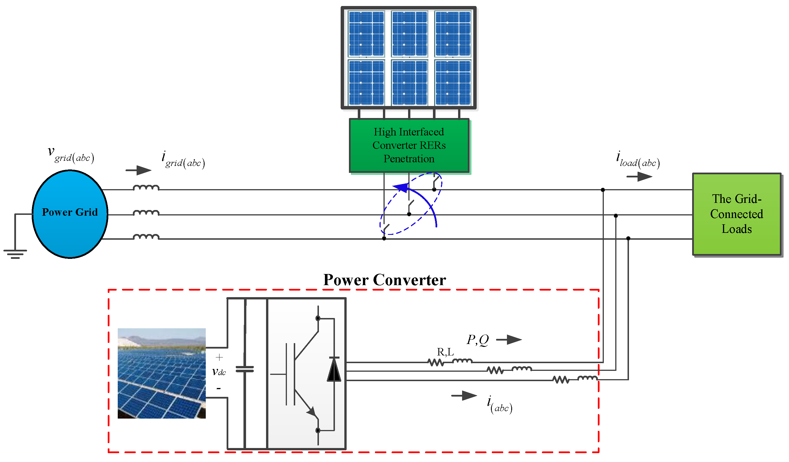
2. The Proposed Control Technique

The main structure of the proposed synchronous active proportional-integral-resonance controller (SAPIRC) is presented in this section. According to Figure 1, the proposed model is comprised of the power grid, the grid-connected load, the RERs, and the interfaced converters. Both connection and disconnection of the large-scale RERs will be implemented in this paper to assess the ability of the proposed control technique to guarantee stable operating conditions for the power grid. To achieve this, a dynamic model will be presented, and subsequently, a control strategy will be proposed based on inherent features of PMSG.

A. The Proposed Dynamic Model Analysis

To draw an appropriate plan to control the interfaced converters between RERs and the power grid, a dynamic analytical model of Figure 1 is developed. Bearing in mind this assumption, the dynamic model based on the power grid specification and d-q voltages at the point of common coupling (PCC) can be achieved as [6]:
L g d i g d d t + R g i g d ω L g i g q = v g d v d  
L g d i g q d t + R g i g q + ω L g i g d = v g q v q  
where the voltage vgdq − vdq shows the magnitude of the grid voltage variation, which should be equal to zero under ideal conditions. As can be seen in Figure 1, the relationship between the grid-connected load, the power grid, and the interfaced converter currents in the d-q reference frame can be expressed as:
i l d q = i g d q + i d q  
By substituting (3) into both (1) and (2), the dynamic equation based on the currents of the interfaced converter can be achieved as:
L g d i d d t + R g i d ω L g i q + v g d v d = v 1 ( i l d , i l q ) L g d i q d t + R g i q + ω L g i d + v g q v q = v 2 ( i l d , i l q )
The voltages v1 and v2 are dependent on the grid-connected load, which can be obtained as:
v 1 ( i l d , i l q ) = R g i l d ω L g i l q v 2 ( i l d , i l q ) = R g i l q + ω L g i l d
Also, as can be understood from (5), the voltages v1 and v2 will be changed by the grid frequency and impedance variation. This feature results in the proposed dynamic model in (4), including all the specifications of grid, load, and interfaced converter.

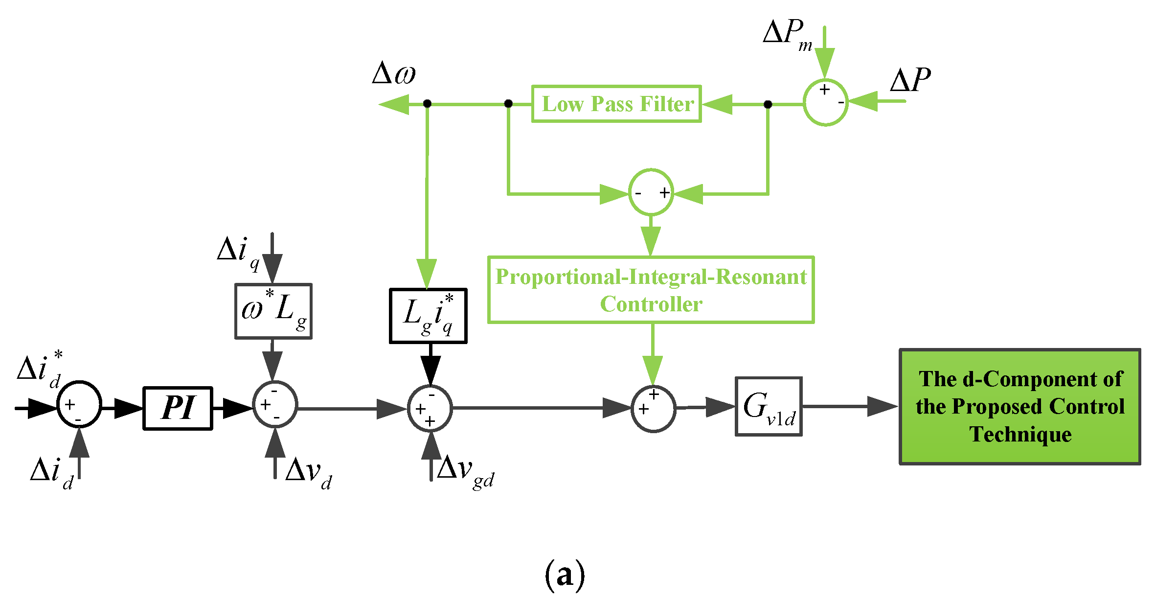
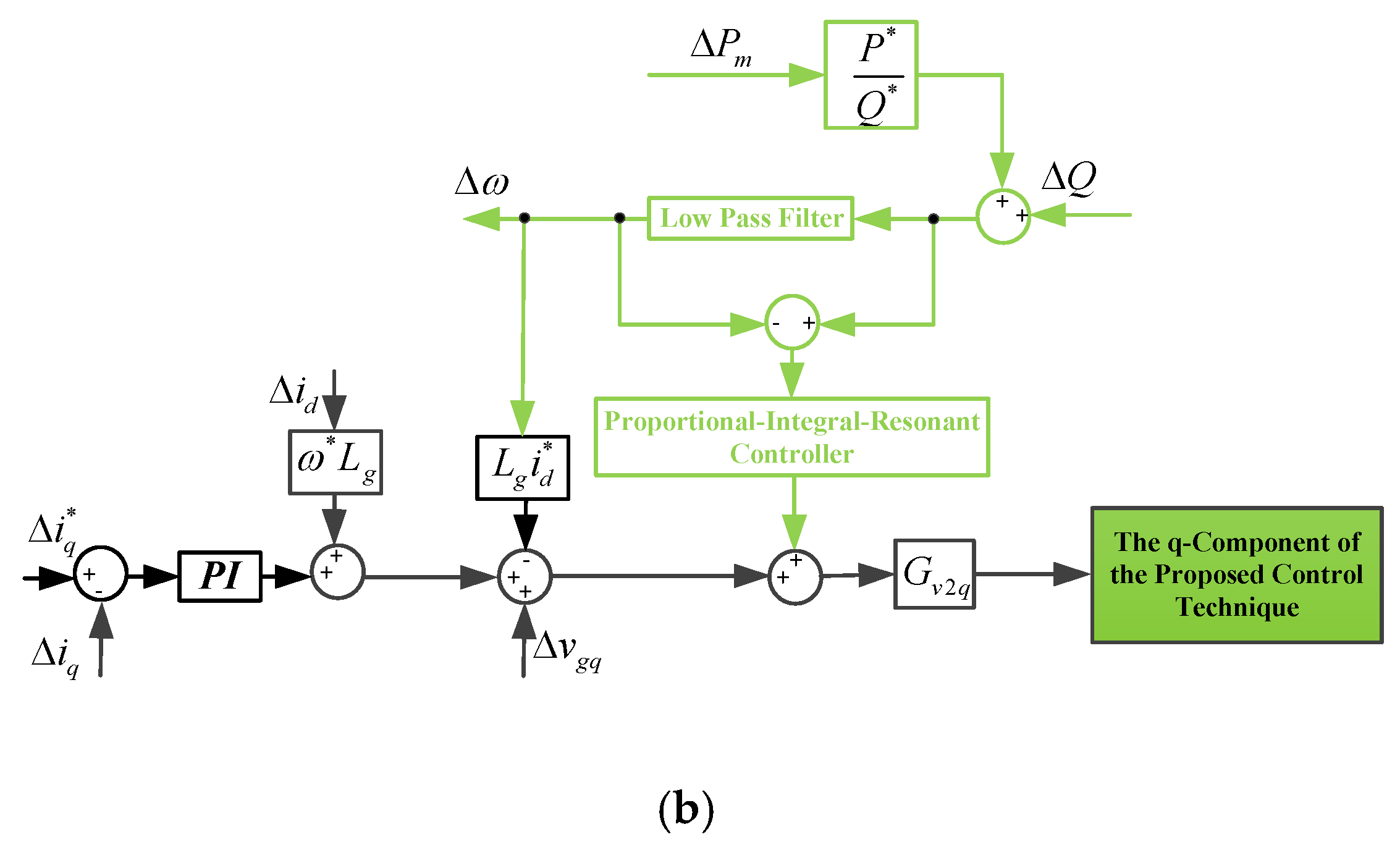
B. The Proposed SAPIRC-Based Controller

In this sub-section, the proposed control technique is presented based on Equation (4) and the inherent characteristics of the PMSG. By applying small signal linearization to (4), the linearized Equations (6) and (7) can be derived as:
( L g s + R g ) Δ i d L g i q * Δ ω ω * L g Δ i q + Δ v g d Δ v d = Δ v 1 ( i l d , i l q )  
( L g s + R g ) Δ i q + L g i d * Δ ω + ω * L g Δ i d + Δ v g q Δ v q = Δ v 2 ( i l d , i l q )  
With an acceptable approximation Δvq = 0, it can be considered that P = vdid. Thus, the small signal linearization of the active power P can be written as:
Δ i d = Δ P v d * Δ v d P * v d * 2  
To achieve the perturbation component of current of the SAPIRC-based converter on the d-axis, the Δvd and Δiq are firstly derived from (6) and (7), respectively, and then the results will be substituted into (8). Thus, (9) can be expressed as:
Δ i d = Δ P ( L g s + R g ) v d * Δ + ( ( L g i q * P * ) ( L g s + R g ) L g i d * ω * L g P * Δ ) Δ ω ( ω * L g P * Δ ) Δ v g q + ( ω * L g P * Δ ) Δ v 2 ( i l d , i l q ) ( P * ) ( L g s + R g ) Δ Δ v g d + ( P * ) ( L g s + R g ) Δ Δ v 1 ( i l d , i l q )
where
Δ = ( P * L g 2 s 2 + ( 2 R g L g P * + v d * 2 L g ) s + ( v d * 2 R g + P * R g 2 + ω * 2 L g 2 P * ) )  
On the other hand, by combining the relationships between P = vdid and Q = − vdiq, the following equation can be expressed as:
P i q = Q i d  
To make a relationship between Δiq and the perturbation components of active and reactive powers of the SAPIRC-based converter, small signal linearization should be applied to (10), which leads to:
Δ i q = ( Δ Q i d * Δ P i q * Q * Δ i d ) / P *  
As can be seen, the perturbation part of q-component of the SAPIRC-based converter current is dependent on all the perturbation parts of Δid, ΔP and ΔQ. The relationship between the electrical and mechanical parts of a PMSG can be stated as the following swing equation [29]:
1 2 J d ( ω 2 ) d t = P m P  
Applying small signal linearization to (12) will lead to:
Δ P = Δ P m ( ω * J s + ( P m * P * ) / ω * ) ( Δ ω )  
As is known, the relationship between the apparent power and both active and reactive powers can be written as P2 + Q2 = S2. When considering a constant value for the apparent power of the SAPIRC-based converter, the following equation can be achieved for the reactive power perturbation part using the stated relation and (13) as:
Δ Q = P * Q * ( ω * J s + ( P m * P * ) / ω * ) ( Δ ω ) P * Q * Δ P m  
By substituting (13) into (9), along with some simplifications, the perturbation component of the d component of the interfaced converter based on PMSG features can be expressed as:
Δ i d = G m d Δ P m + G p d Δ P G g q d Δ v g q + G v 2 d Δ v 2 G g d d Δ v g d + G v 1 d Δ v 1  
where various transfer functions of (15) are as follows:
G m d = [ P * L g 2 i q * s + ( R g P * L g i q * P * ω * L g 2 i d * ) ] Δ d G p d = ( J ω * v d * L g s 2 + [ ( ( P m * P * ) / ω * ) v d * L g + J ω * v d * R g P * L g 2 i q * ] s + [ ( ( P m * P * ) / ω * ) v d * R g R g P * L g i q * + P * ω * L g 2 i d * ] ) Δ d   G g q d = ( J P * ω * 2 L g s + ( P m * P * ) P * L g ) Δ d   G v 2 d = ( J P * ω * 2 L g s + ( P m * P * ) P * L g ) Δ d   G g d d = ( J ω * L g P * s 2 + [ ( ( P m * P * ) / ω * ) L g P * + J ω * R g P * ] s + ( ( P m * P * ) / ω * ) R g P * ) Δ d   G v 1 d = ( J ω * L g P * s 2 + [ ( ( P m * P * ) / ω * ) L g P * + J ω * R g P * ] s + ( ( P m * P * ) / ω * ) R g P * ) Δ d   Δ d = ( P * L g 2 J ω * s 3 + [ ( v d * 2 L g + 2 P * R g L g ) J ω * + + P * L g 2 ( ( P m * P * ) / ω * ) ] s 2 + [ ( R g 2 P * + P * ω * 2 L g 2 + v d * 2 R g ) J ω * + ( v d * 2 L g + 2 P * R g L g ) ( ( P m * P * ) / ω * ) ] s + ( R g 2 P * + P * ω * 2 L g 2 + v d * 2 R g ) ( ( P m * P * ) / ω * ) )  
Also, by substituting (13)–(15) into (11), the relationship between Δiq based on the proposed model and the PMSG specifications can be expressed as:
Δ i q = G m q Δ P m G p q Δ P G q q Δ Q + G g q q Δ v g q G v 2 q Δ v 2 + G g d q Δ v g d G v 1 q Δ v 1  
The entirety of the transfer functions used in (16) can be written as:
G m q = [ Q * P * L g 2 i q * s + Q * ( R g P * L g i q * P * ω * L g 2 i d * ) ] Δ q   G p q = ( P * L g 2 J ω * i q * s 3 + [ ( v d * 2 L g + 2 P * R g L g ) J ω * i q * + + P * L g 2 i q * ( ( P m * P * ) / ω * ) + Q * J ω * v d * L g ] s 2   + [ ( R g 2 P * + P * ω * 2 L g 2 + v d * 2 R g ) i q * J ω * + ( v d * 2 L g + 2 P * R g L g ) i q * ( ( P m * P * ) / ω * ) + Q * [ ( ( P m * P * ) / ω * ) v d * L g + J ω * v d * R g P * L g 2 i q * ] ] s   + ( R g 2 P * i q * + i q * P * ω * 2 L g 2 + i q * v d * 2 R g ) ( ( P m * P * ) / ω * )   + [ ( ( P m * P * ) / ω * ) v d * R g R g P * L g i q * + P * ω * L g 2 i d * ] Q *   ) Δ q G q q = ( P * L g 2 J ω * s 3 + [ ( v d * 2 L g + 2 P * R g L g ) J ω * + + P * L g 2 ( ( P m * P * ) / ω * ) ] s 2 + [ ( R g 2 P * + P * ω * 2 L g 2 + v d * 2 R g ) J ω * + ( v d * 2 L g + 2 P * R g L g ) ( ( P m * P * ) / ω * ) ] s + ( R g 2 P * + P * ω * 2 L g 2 + v d * 2 R g ) ( ( P m * P * ) / ω * ) ) i d * Δ q   G g q q = ( J P * ω * 2 L g Q * s + ( P m * P * ) Q * P * L g ) Δ q   G v 2 q = ( J P * ω * 2 L g Q * s + ( P m * P * ) Q * P * L g ) Δ q   G g d q = ( J ω * L g P * Q * s 2 + [ ( ( P m * P * ) / ω * ) L g P * + J ω * R g P * ] Q * s + ( ( P m * P * ) / ω * ) R g P * Q * ) Δ q   G v 1 q = ( J ω * L g P * Q * s 2 + [ ( ( P m * P * ) / ω * ) L g P * + J ω * R g P * ] Q * s + ( ( P m * P * ) / ω * ) R g P * Q * ) Δ q   Δ q = ( P * 2 L g 2 J ω * s 3 + [ ( v d * 2 L g + 2 P * R g L g ) J P * ω * + + P * 2 L g 2 ( ( P m * P * ) / ω * ) ] s 2 + [ ( R g 2 P * 2 + P * 2 ω * 2 L g 2 + P * v d * 2 R g ) J ω * + ( v d * 2 P * L g + 2 P * 2 R g L g ) ( ( P m * P * ) / ω * ) ] s + ( R g 2 P * 2 + P * 2 ω * 2 L g 2 + P * v d * 2 R g ) ( ( P m * P * ) / ω * ) )
It can be seen from (15) and (16) that the perturbation part of both the d and q components of the SAPIRC-based converter current can be changed by the mechanical parameters, including the virtual inertia, the reference value of mechanical power, and the virtual mechanical power error. By noticing this role of the mechanical properties, the proposed control technique can be shown as in Figure 2a,b. The proposed control strategy is designed based on Equations (13)–(16), in which the angular frequency error is generated by passing the mechanical power error from a LPF, while two separate PI controllers are considered for the current errors. To further emulate the inherent behaviors of PMSG, both mechanical power and angular frequency errors are involved with the proposed control technique by passing from the related transfer function and relation, as well as a PIR controller, as shown in Figure 2a,b. The considered resonant controller will be defined as follows:
[ R ] ( s ) = 2 k r ω c s s 2 + 2 ω c s + ω 0 2  
The coefficients of kr, ωc and ω0 given in Table 1 are chosen in order to minimize the fluctuations of active and reactive power. It can be noted that, observing Figure 2a,b, the resonant controller of (17) is combined with its related PI controller, which is related to the characteristics of PMSG to provide a stable performance for the ultimate control technique.

3. Assessment of the Power Converter Currents

In accordance with (15) and (16), the Nyquist diagrams of Δid and Δiq given in Table 1 are shown in Figure 3 and Figure 4, respectively, based on the constant value of the virtual mechanical power error, the d component of the grid voltage, and the power converter active and reactive power. In addition to Table 1 for reference and parameter values, other values needed for drawing Figure 3, Figure 4, Figure 5, Figure 6 and Figure 7 can be stated as Δ P m = 100 W, Δ ω = 0.1 Hz, Δ v d = 5 V and Δ v q = 0 V. As can be seen from Figure 3, the response of Δid is stable, and very low amplitude can also be achieved for this error, which verifies the appropriate performance of the proposed control technique. Taking into account this issue, the lowest value belongs to the variations of ΔPm, which shows the damped effects of the virtual mechanical power error, as illustrated in Figure 3a. According to Figure 4, Δiq can achieve stable response under operating conditions. On the other hand, the lowest value for Δiq is due to the reactive power error as depicted in Figure 4c. Taken together, Figure 3 and Figure 4 verify a stable tracking for the SAPIRC-based power converter.

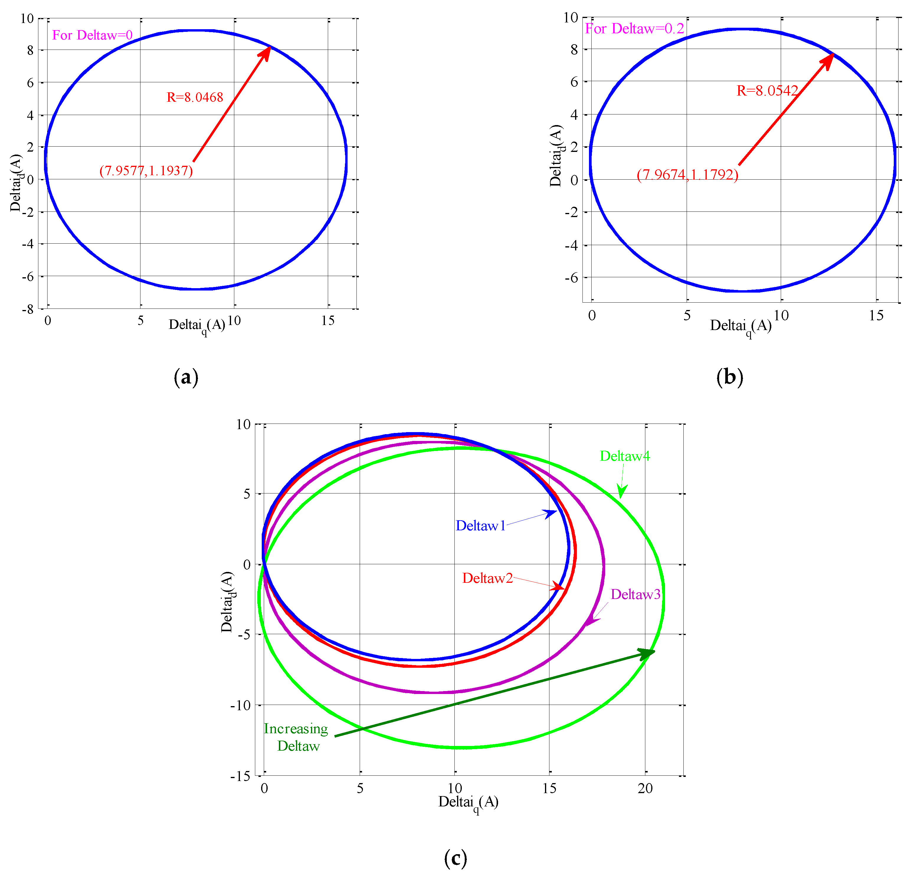
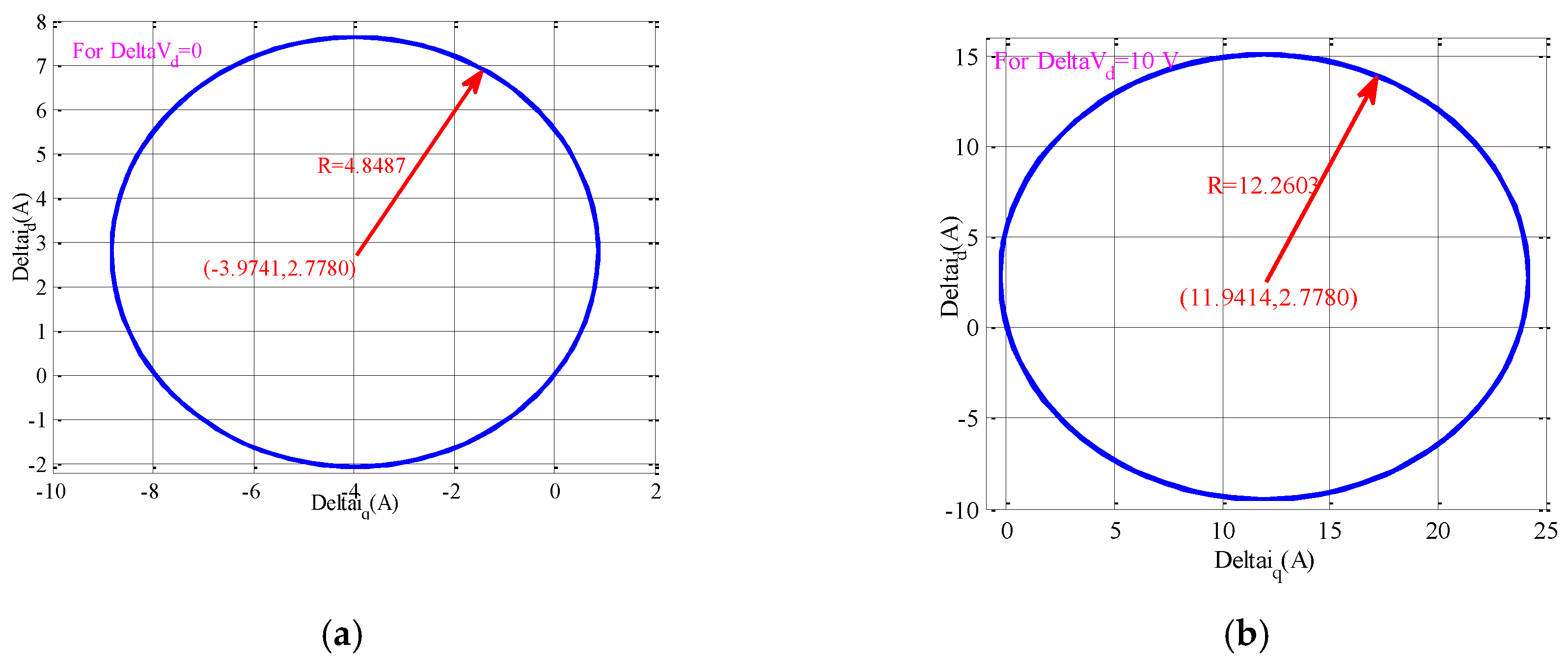
4. Assessment of the Proposed Current Perturbation Curve (CPC)

In this section, perturbations in both the d and q current components of the SAPIRC-based converter will be influenced by the grid frequency and voltage magnitude alterations. In the first step, an area based on various operating points for these components will be achieved. By incorporating Equations (6) and (7), (18) can be expressed as:
( Δ i q + L g i q * Δ ω Δ ( v g d v d ) + Δ v 1 2 ω * L g ) 2 + ( Δ i d + L g i d * Δ ω + Δ v g q Δ v 2 2 ω * L g ) 2 = ( L g i q * Δ ω Δ ( v g d v d ) + Δ v 1 2 ω * L g ) 2 + ( L g i d * Δ ω + Δ v g q Δ v 2 2 ω * L g ) 2
Equation (18) is the perturbation curve of SAPIRC, which is shown in Figure 5. This figure verifies how much the variations of grid angular frequency error can influence the alteration zone of Δid and Δiq. By using the system parameters given in Table 1, it is clearly specified in Figure 5a,b that there is a slight difference between the center coordinates and radius of the two generated CPCs due to the two acceptable minimum and maximum values of error in the grid angular frequency. Apart from the grid angular frequency error, choosing the desired value of zero and also the allowable maximum value for the grid voltage magnitude will lead to Figure 6a,b, respectively, in which a large difference between the achieved center coordinates and radius values is depicted. These results confirm that the variations of grid voltage magnitude can impact the current perturbation components much more than the angular frequency error alterations. On the other hand, increasing the grid angular frequency error can expand the operating region of the current perturbation curve, according to Figure 5c. This expansion is more visible for much larger values of Δω3 and Δω4. For variations in grid voltage magnitude error, the noticeable expansion of the CPC starts from the first step of the increasing process, as shown in Figure 6c. Based on Figure 6c, the spreading out of the CPC due to the increment in error of the grid voltage magnitude takes place in such a way that sometimes the perturbation values of the SAPIRC-based converter current are not acceptable for continuing operation of the proposed model.

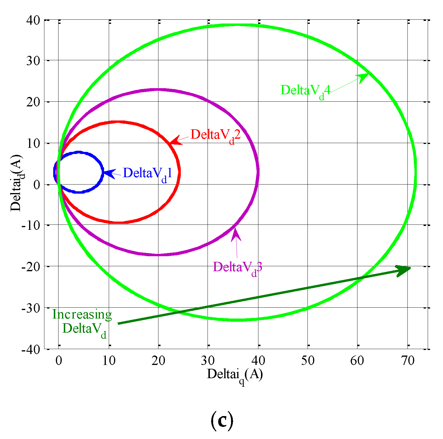
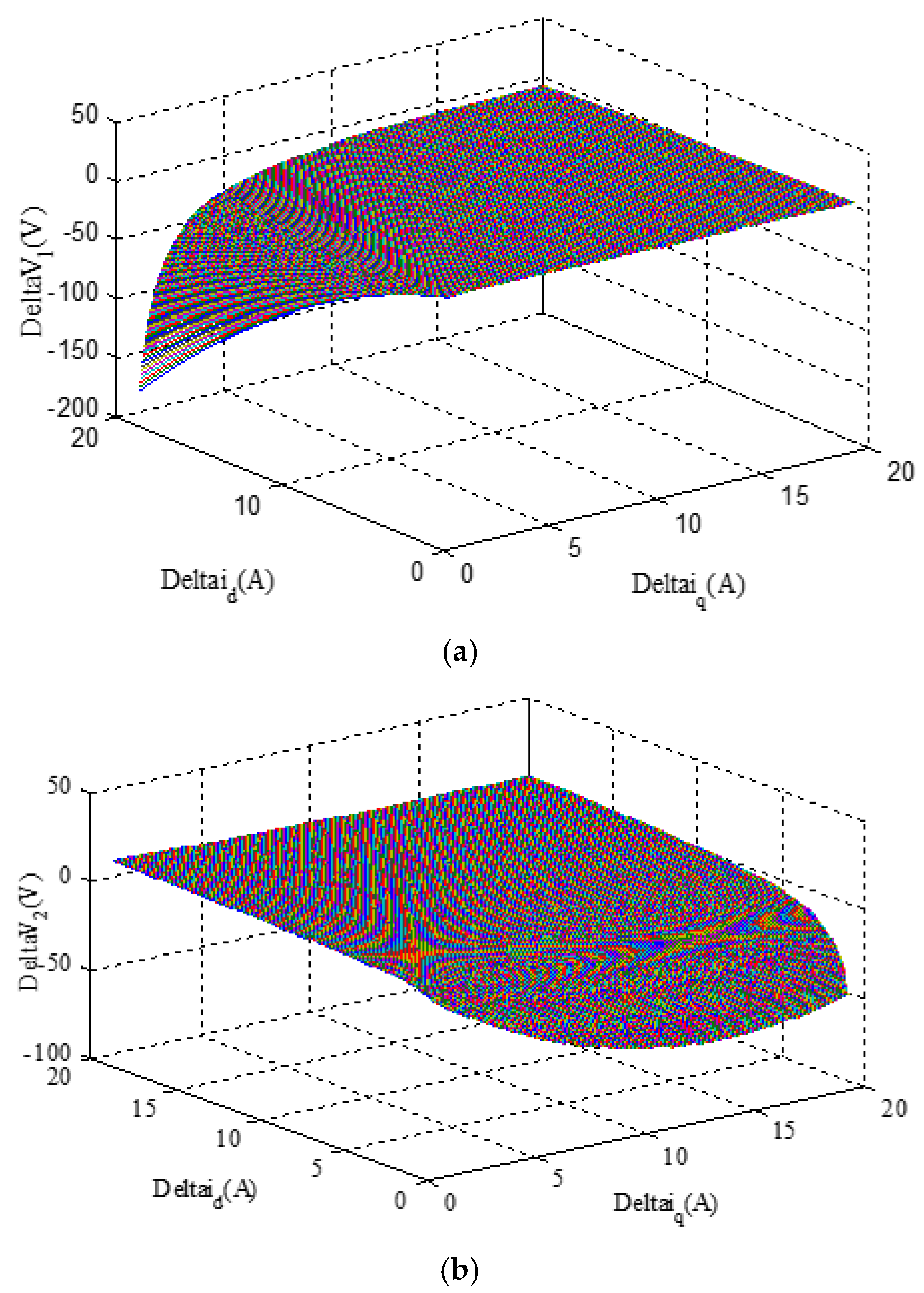
5. Effects of the Current Perturbation Components on the Load-Based Voltage.

The voltages of Δv1 and Δv2 that are due to the load current errors can be affected by the current perturbation components of Δid and Δiq. In order to appropriately supply a load, very low values for the load current errors are required, which subsequently leads to a significant decrement in both Δv1 and Δv2. By using (6) and (7), the following equation can be expressed:
F ( Δ i q , Δ i d , Δ v 1 , Δ v 2 ) = Δ i q 2 + Δ i d 2 + ( Δ v 1 ω * L g ) Δ i q ( Δ v 2 ω * L g ) Δ i d + ( L g i q * Δ ω Δ ( v g d v d ) ω * L g ) Δ i q + ( L g i d * Δ ω + Δ v g q ω * L g ) Δ i d = 0
The load-based voltages are considered separately to assess the effects of the current perturbation components. Initially, by assuming Δv2 = 0 and then Δv1 = 0 in (19), the following relationships can be derived for Δv1 and Δv2, respectively, as:
F ( Δ i q , Δ i d , Δ v 1 , 0 ) Δ v 2 = 0 = F 1 = 0 Δ v 1 = Δ i q 2 + Δ i d 2 + ( L g i q * Δ ω Δ ( v g d v d ) ω * L g ) Δ i q + ( L g i d * Δ ω + Δ v g q ω * L g ) Δ i d ( Δ i q ω * L g )
F ( Δ i q , Δ i d , 0 , Δ v 2 ) Δ v 1 = 0 = F 2 = 0 Δ v 2 = Δ i q 2 + Δ i d 2 + ( L g i q * Δ ω Δ ( v g d v d ) ω * L g ) Δ i q + ( L g i d * Δ ω + Δ v g q ω * L g ) Δ i d ( Δ i d ω * L g )
Two three-dimensional diagrams based on (20) and (21) are depicted in Figure 7a,b, respectively. It can be seen from Figure 7a,b that the zero values of the current perturbation components are able to maintain the load-based voltages at their desired value of zero. In addition to very low values of Δid and Δiq, another desirable case for Δv1 is achieved with high values of Δiq and small values of Δid, which causes the load-based voltages of Δv1 to approach zero, as illustrated in Figure 7a. Inversely, the large and small values for Δid and Δiq, respectively, lead to a dramatic increment of Δv1, as shown in Figure 7a. On the other hand, as can be seen from Figure 7b, an inverse progression happens for Δv2 in comparison with Δv1. This means that large and small values of Δiq and Δid, respectively, represent an undesirable case for Δv2. According to Figure 7b, increasing Δid and decreasing Δiq can lead to obtaining an approximately zero value for Δv2. The aforementioned assessments of the load-based voltages variations result in reaching a point at which the correct operation of the SAPIRC for supplying the required currents of the considered loads can be only obtained when Δid and Δiq approach very low or zero values. Thus, it is worth mentioning that increasing one of the two current perturbation components will surely lead to unsuitable performance of the SAPIRC, leading to an unstable power grid.

6. Results and Discussion

The ability of the proposed control technique is evaluated in this section. To present a suitable assessment, the effects of the integration of large-scale RERs, as well as the effects of the resonant factor variations on the proposed control technique are investigated. The simulation parameters are given in Table 1. The general structures of all considered scenarios under simulation are illustrated in Figure 8a,b.

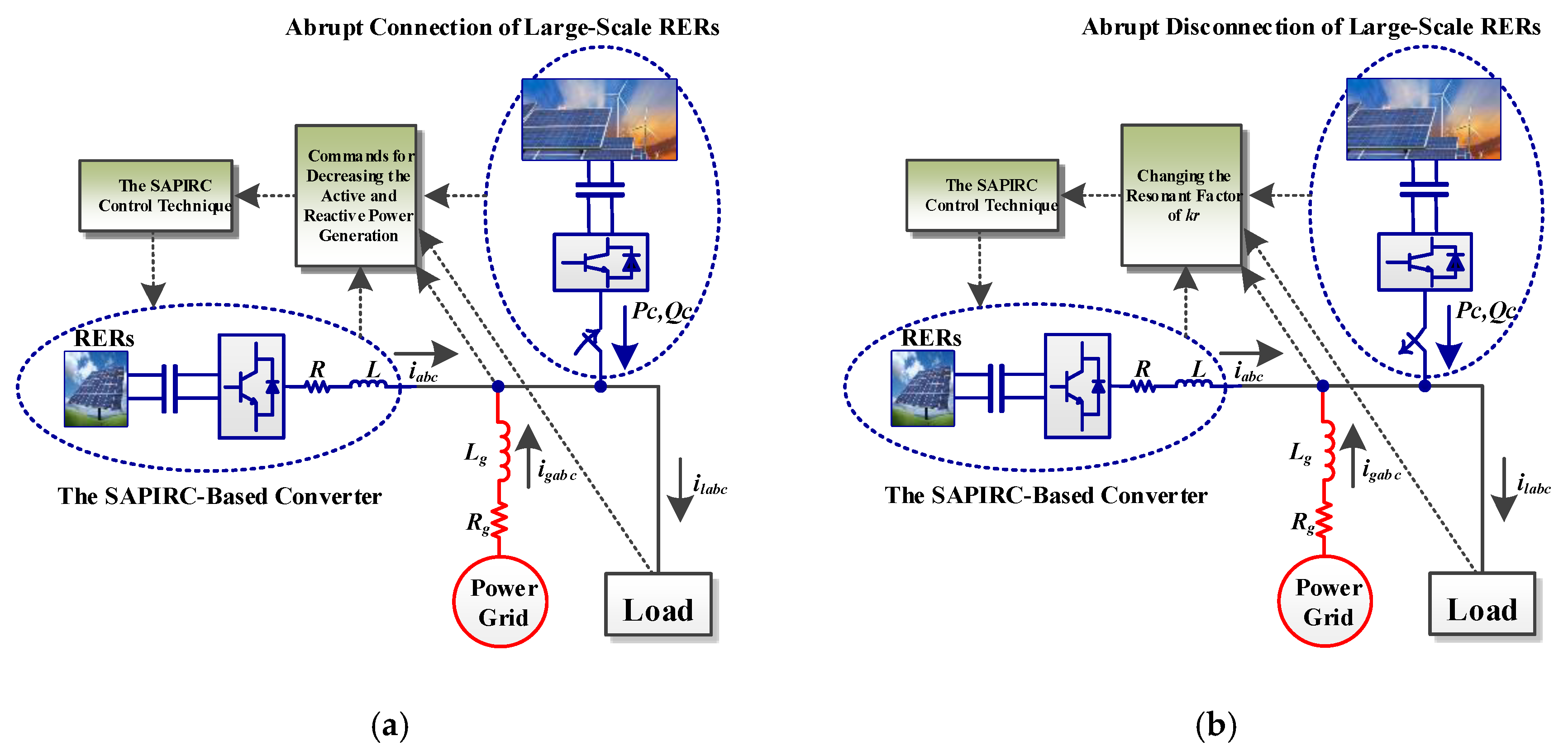
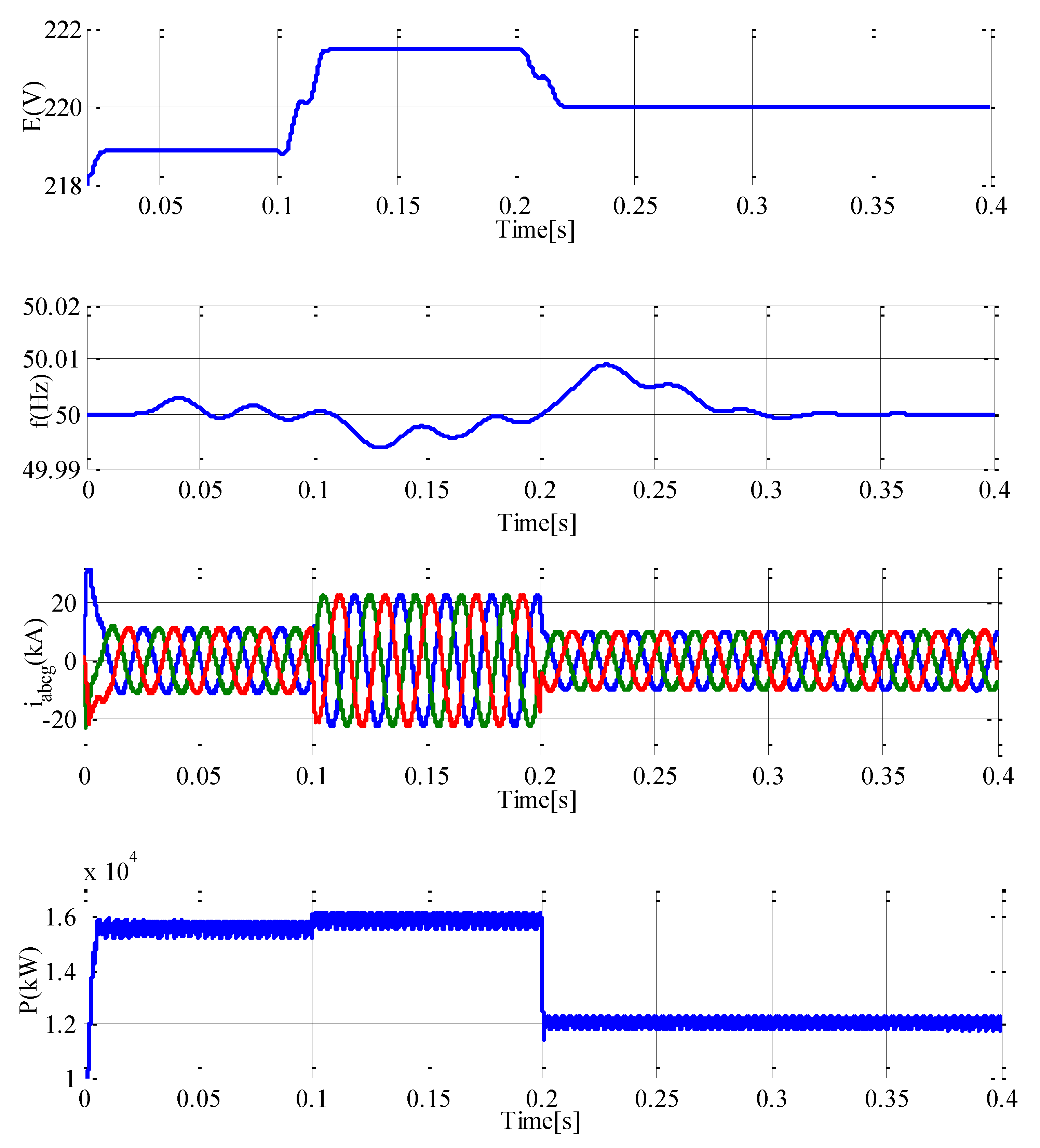
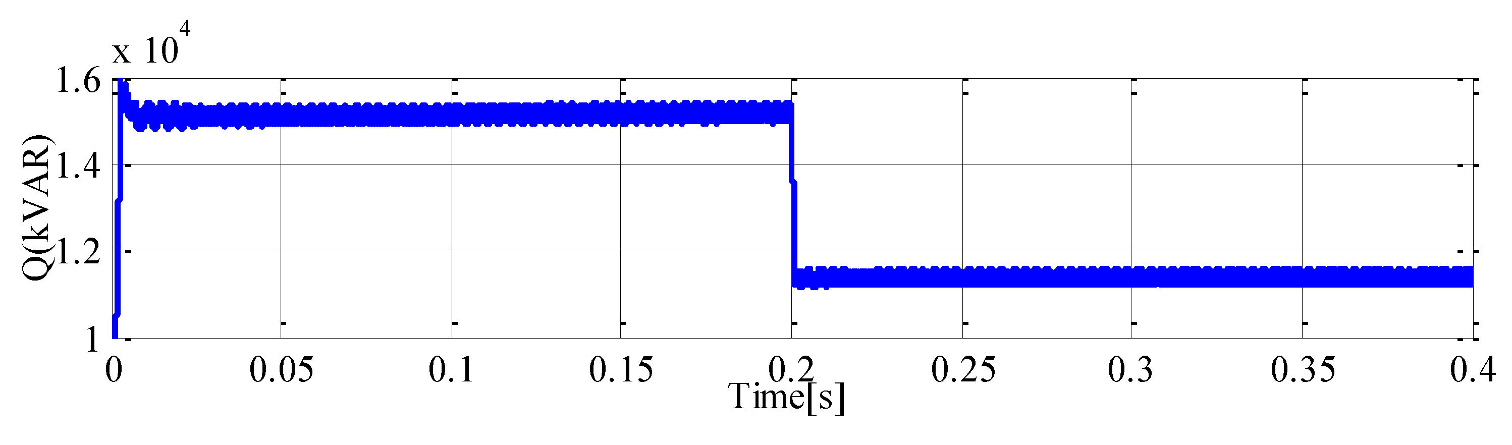
A. Effects of the Sudden Connection of Large-Scale RERs

Figure 8a shows the conditions considered in this sub-section. Initially, the power grid and the power converter supply the grid-connected load. Then, at t = 0.1 s, the connection of the large-scale RERs takes place and an additional active and reactive power of 11 MW + j10 MVAR is injected to the power grid. After that, the proposed control technique-based converter is implemented at t = 0.2 s to support the power grid in reaching stable operating conditions. In the interval (0, 0.1 s), because of the need for the power grid to cover part of the load demand, the grid voltage magnitude is below its desired value and also the grid frequency experiences some fluctuations, as depicted in Figure 9. Under these conditions, the grid current will be as shown in Figure 9. Since the grid voltage magnitude and frequency are not equal to their reference values, the power converter generates its active and reactive power with a small error, as illustrated in Figure 9. After the abrupt integration of the large-scale RERs into the power grid at t = 0.2 s, the grid voltage magnitude rises, and the grid frequency decreases, as shown in Figure 9. These variations are due to the injection of additional active and reactive power into the power grid, whereby the grid current increases, as shown in Figure 9. As can be seen, the alterations of the grid voltage magnitude and frequency will lead to higher error in the active and reactive power injection by the power converter at time interval (0.1, 0.2 s). To amend the grid voltage magnitude and frequency, the additional injected active and reactive power should be compensated. Thus, by noticing the amount of the additional injected power, the power converter operates at t = 0.2 s to decrease its active and reactive power injection. Based on Figure 9, after an acceptable transient response, the grid voltage magnitude and frequency appropriately follow their desired values. Also, in contrast to the uncompensated state, as predicted, the grid currents will decrease.

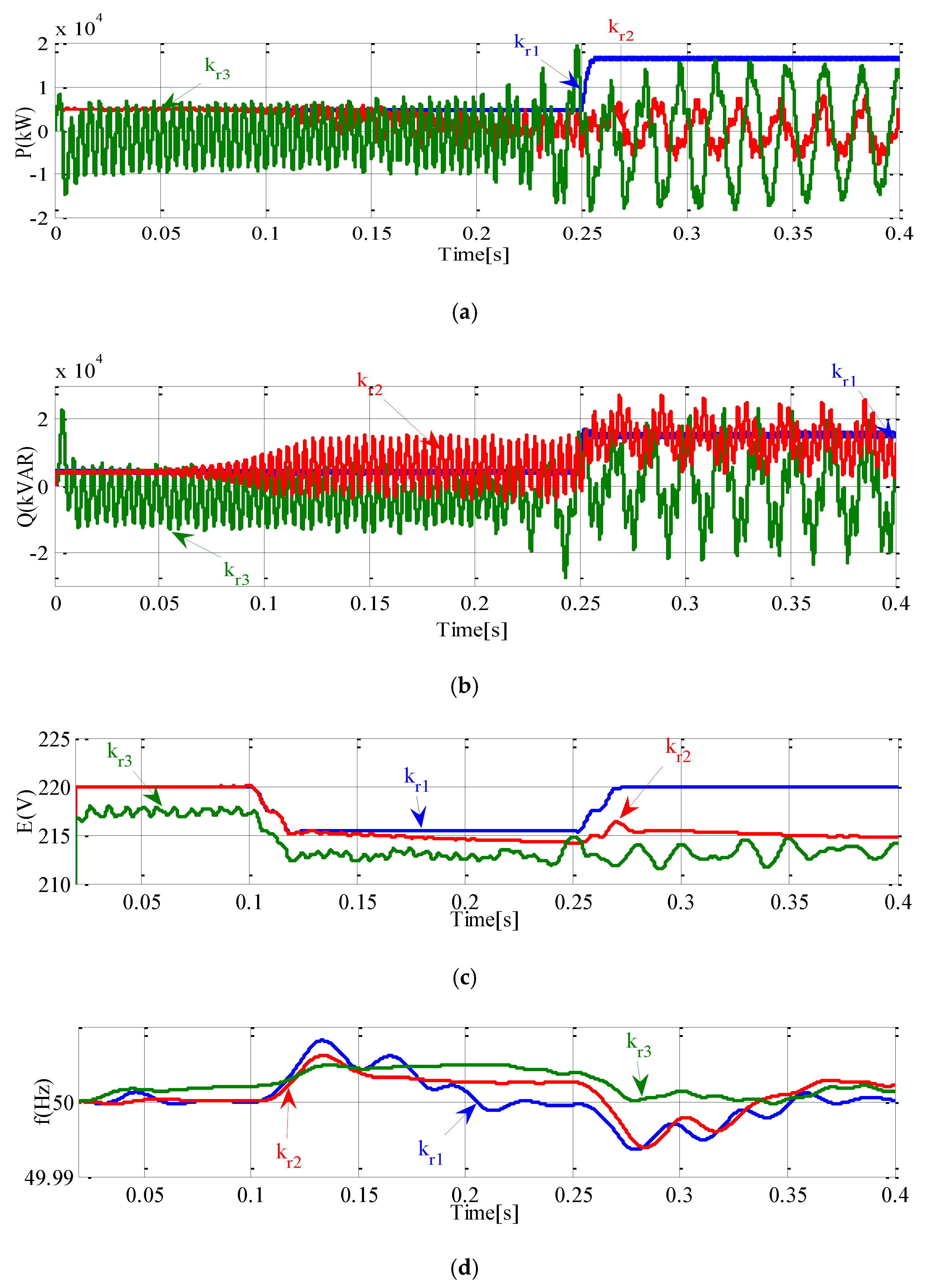
B. Assessment of the Effects of Resonant Factor Variations

In this sub-section, how much the resonant factor can impact the performance of the proposed control technique is investigated, as shown in Figure 8b. The considered scenario is the disconnection of the large-scale RERs, which happens at t = 0.1 s, and the power converter compensates this disconnection at t = 0.25 s. Figure 10 demonstrates the active and reactive power of the SAPIRC-based converter, the grid voltage magnitude, and the grid frequency under small (kr1), large (kr2) and very large (kr3) values of the resonant factor. These values are 1 × 101, 1 × 10³ and 1 × 10⁵ for kr1, kr2 and kr3, respectively. For the case of kr1, all the considered state variables maintain their stable operation in both steady-state and dynamic operating conditions, as depicted in Figure 10. As can be seen from Figure 10, the reactive power becomes unstable faster than the active power for the case of kr2. However, active and reactive powers in both power converters fluctuate greatly after t = 0.1 s when considering the resonant factor of kr2. It should be noted that the reactive power fluctuations happen on the routes of its reference value, as shown in Figure 10b. Also, except for the time interval (0, 0.1 s), both the grid voltage magnitude and frequency exhibit unstable behavior for the case of kr2, as demonstrated in Figure 10c,d, respectively. In contrast with kr1, all of the state variables are completely disturbed by choosing the very large value of kr3. Based on Figure 10, the worst case belongs to the active power of the power converter, which oscillates with a very wide amplitude of fluctuations.

7. Conclusions

A synchronous resonant control technique has been presented in this paper to address power grid instability problems due to the high penetration of renewable energy resources. After applying small signal linearization to a dynamic model with state variables, i.e., the grid parameters, the load-based voltages, and currents of the proposed control-based converter, the linearized relationships based on the inherent features of the PMSG and the apparent power of the interfaced converter were utilized to add a new functionality to the control loop of the interfaced converter based on the behavior of the synchronous generator. As a contribution of the proposed control strategy, a comprehensive relationship between interfaced converter model and PMSG inherent swing equations has been established. Also, the impacts of the errors of virtual mechanical power, the d-axis of the grid voltage, and the active and reactive power of the interfaced converter were applied to the converter currents errors. To further analyze the power grid frequency and voltage magnitude errors, a CPC was introduced. Moreover, the appropriate operation for supplying the grid-connected loads was accurately assessed through the perturbation components variation analysis of the proposed controller-based converter currents. Simulation results confirmed the ability of the proposed control technique to guarantee stable operation of the power grid under high penetration of renewable energy resources.

Author Contributions

All authors worked on this manuscript together and all authors have read and approved the final manuscript.

Funding

This research was funded by FEDER funds through COMPETE 2020, Portuguese funds through FCT, under Projects SAICT-PAC/0004/2015-POCI-01-0145-FEDER-016434, POCI-01-0145-FEDER-006961, UID/EEA/50014/2013, UID/CEC/50021/2013, UID/EMS/00151/2013, 02/SAICT/2017-POCI-01-0145-FEDER-029803, and the EU 7th Framework Programme FP7/2007-2013 under GA no. 309048.

Acknowledgments

J.P.S. Catalão acknowledges the support by FEDER funds through COMPETE 2020 and by Portuguese funds through FCT, under Projects SAICT-PAC/0004/2015—POCI-01-0145-FEDER-016434, POCI-01-0145-FEDER-006961, UID/EEA/50014/2013, UID/CEC/50021/2013, UID/EMS/00151/2013, and 02/SAICT/2017—POCI-01-0145-FEDER-029803, and also funding from the EU 7th Framework Programme FP7/2007-2013 under GA no. 309048.

Conflicts of Interest

The authors declare no conflict of interest.

Nomenclature

Parameters
RgGrid Resistance
LgGrid Inductance
JMoment of Inertia
Variables
idqConverter Currents
ildqLoad Currents
igdqGrid Currents
ΔidqPerturbation Components of idq
ΔildqPerturbation Components of ildq
ΔigdqPerturbation Components of igdq
vdqConverter Voltage Magnitudes
vgdqGrid Voltage Magnitudes
v12Load-Based Voltages
ΔvdqPerturbation Components of vdq
Δv12Perturbation Components of v12
ΔvgdqPerturbation Components of vgdq
PmMechanical Power
P, Q, SActive, Reactive and Apparent Power of SAPIRC-Based Converter
ωGrid Angular Frequency
ΔP, ΔQPerturbation Components of P and Q
ΔPmPerturbation Components of Pm
ΔωPerturbation Components of ω
i*dqReference Values of idq
v*dqReference Values of vdq
P*, Q*Reference Values of P,Q
P*mReference Values of Pm
ω*Reference Values of ω
Δi*dqReference Values of Δidq
kpdq, kidqPI Controller Coefficients
krResonant Factor
ω0, ωcFrequencies of Resonant Controller
Abbreviation
SAPIRCSynchronous Active Proportional Integral Resonant Controller
PMSGPermanent Magnet Synchronous Generator
CPCCurrent Perturbation Curve
RERsRenewable Energy Resources
LPFLow Pass Filter
PIProportional Integral
PVPhotovoltaic

References

  1. Valenciaga, F.; Puleston, P.F.; Battaiotto, P.E.; Mantz, R.J. Passivity/sliding mode control of a stand-alone hybrid generation system. IEE Proc.—Control Theory Appl. 2000, 147, 680–686. [Google Scholar] [CrossRef]
  2. Hosseinzadeh, M.; Salmasi, F.R. Power management of an isolated hybrid AC/DC micro-grid with fuzzy control of battery banks. IET Renew. Power Gener. 2015, 9, 484–493. [Google Scholar] [CrossRef]
  3. Hosseinzadeh, M.; Salmasi, F.R. Robust optimal power management system for a hybrid AC/DC micro-grid. IEEE Trans. Sustain. Energy 2015, 6, 675–687. [Google Scholar] [CrossRef]
  4. Hosseinzadeh, M.; Salmasi, F.R. Analysis and detection of a wind system failure in a micro-grid. J. Renew. Sustain. Energy 2016, 8. [Google Scholar] [CrossRef]
  5. Mehrasa, M.; Pouresmaeil, E.; Zabihi, S.; Rodrigues, E.M.G.; Catalao, J.P.S. A control strategy for the stable operation of shunt active power filters in power grids. Energy 2016, 96, 325–334. [Google Scholar] [CrossRef]
  6. Pouresmaeil, E.; Mehrasa, M.; Shokridehaki, M.A.; Rodrigues, E.M.G.; Catalao, J.P.S. Control and stability analysis of interfaced converter in distributed generation technology. In Proceedings of the IEEE EUROCON 2015—International Conference on Computer as a Tool (EUROCON), Salamanca, Spain, 8–11 September 2015; pp. 1–6. [Google Scholar]
  7. Pouresmaeil, E.; Mehrasa, M.; Erdinc, O.; Catalao, J.P.S. A control algorithm for the stable operation of interfaced converters in microgrid systems. In Proceedings of the IEEE PES Innovative Smart Grid Technologies, Istanbul, Turkey, 12–15 October 2014; pp. 1–6. [Google Scholar]
  8. Mei, J.; Xiao, B.; Shen, K.; Tolbert, L.M.; Zheng, J.Y. Modular multilevel inverter with new modulation method and its application to photovoltaic grid-connected generator. IEEE Trans. Power Electron. 2013, 28, 5063–5073. [Google Scholar] [CrossRef]
  9. Pouresmaeil, E.; Mehrasa, M.; Shokridehaki, M.A.; Rodrigues, E.M.G.; Catalao, J.P.S. Control of modular multilevel converters for integration of distributed generation sources into the power grid. In Proceedings of the IEEE International Conference on Smart Energy Grid Engineering (SEGE), Oshawa, ON, Canada, 17–19 August 2015; pp. 1–6. [Google Scholar]
  10. Hasanzadeh, A.; Edrington, C.S.; Stroupe, N.; Bevis, T. Real-time emulation of a high-speed microturbine permanent-magnet synchronous generator using multiplatform hardware-in-the-loop realization. IEEE Trans. Ind. Electron. 2014, 61, 3109–3118. [Google Scholar] [CrossRef]
  11. Griffo, A.; Drury, D. Hardware in the loop emulation of synchronous generators for aircraft power systems. Electr. Syst. Aircr. Railw. Ship Propuls. (ESARS) 2012. [Google Scholar] [CrossRef]
  12. Valencia, F.; Puleston, P.F. Variable structure control of a wind energy conversion system based on a brushless doubly fed reluctance generator. IEEE Trans. Energy Convers. 2007, 22, 499–506. [Google Scholar] [CrossRef]
  13. Valencia, F.; Puleston, P.F.; Battaiotto, P.E. Power control of a photovoltaic array in a hybrid electric generation system using sliding mode techniques. IEE Proc. Control Theory Appl. 2001, 148, 448–455. [Google Scholar] [CrossRef]
  14. Pradhan, R.; Subudhi, B. Double integral sliding mode MPPT control of a photovoltaic system. IEEE Trans. Control Syst. Technol. 2016, 24, 285–292. [Google Scholar] [CrossRef]
  15. Hosseinzadeh, M.; Salmasi, F.R. Determination of maximum solar power under shading and converter faults—A prerequisite for failure-tolerant power management systems. Simul. Model. Pract. Theory 2016, 62, 14–30. [Google Scholar] [CrossRef]
  16. Torres, M.A.; Lopes, L.A.; Moran, L.A.; Espinoza, J.R. Self-tuning virtual synchronous machine: A control strategy for energy storage systems to support dynamic frequency control. IEEE Trans. Energy Convers 2014, 29, 833–840. [Google Scholar] [CrossRef]
  17. D’Arco, S.; Suul, J.A.; Fosso, O.B. A virtual synchronous machine implementation for distributed control of power converters in smart grids. Electric Power Syst Res. 2015, 122, 180–197. [Google Scholar] [CrossRef]
  18. Sarkar, M.N.I.; Meegahapola, L.G.; Datta, M. Reactive power management in renewable rich power grids: A review of grid-codes, renewable generators, support devices, control strategies and optimization algorithms. IEEE Access 2018, 6, 41458–41489. [Google Scholar] [CrossRef]
  19. Ou, T.C.; Hong, C.M. Dynamic operation and control of microgrid hybrid power systems. Energy 2014, 66, 314–323. [Google Scholar] [CrossRef]
  20. Hong, C.M.; Ou, T.C.; Lu, K.H. Development of intelligent MPPT (maximum power point tracking) control for a grid-connected hybrid power generation system. Energy 2013, 50, 270–279. [Google Scholar] [CrossRef]
  21. Lin, W.M.; Hong, C.M.; Ou, T.C.; Chiu, T.M. Hybrid intelligent control of PMSG wind generation system using pitch angle control with RBFN. Energy Convers. Manag. 2011, 52, 1244–1251. [Google Scholar] [CrossRef]
  22. Ou, T.C.; Lu, K.H.; Huang, C.J. Improvement of transient stability in a hybrid power multi-system using a designed NIDC (Novel Intelligent Damping Controller). Energies 2017, 10, 488. [Google Scholar] [CrossRef]
  23. Ou, T.C. A novel unsymmetrical faults analysis for microgrid distribution systems. Int. J. Electr. Power Energy Syst. 2012, 43, 1017–1024. [Google Scholar] [CrossRef]
  24. Ou, T.C. Ground fault current analysis with a direct building algorithm for microgrid distribution. Int. J. Electr. Power Energy Syst. 2013, 53, 867–875. [Google Scholar] [CrossRef]
  25. Lyu, X.; Zhao, J.; Jia, Y.; Xu, Z.; Wong, K.P. Coordinated control strategies of PMSG-based wind turbine for smoothing power fluctuations. IEEE Trans. Power Syst. 2018. [Google Scholar] [CrossRef]
  26. Mendis, N.; Muttaqi, K.M.; Perera, S. Management of battery-supercapacitor hybrid energy storage and synchronous condenser for isolated operation of PMSG based variable-speed wind turbine generating systems. IEEE Trans. Smart Grid 2014, 5, 944–953. [Google Scholar] [CrossRef]
  27. Li, M.; Wang, Y.; Xu, N.; Liu, Y.; Wang, W.; Wang, H.; Lei, W. A novel virtual synchronous generator control strategy based on improved swing equation emulating and power decoupling method. In Proceedings of the 2016 IEEE Energy Conversion Congress and Exposition (ECCE), Milwaukee, WI, USA, 18–22 September 2016; pp. 1–6. [Google Scholar]
  28. Mehrasa, M.; Gordina, R.; Pouresmaeil, E.; Vechiu, I.; Rodrigues, R.L.; Catalao, J.P.S. Synchronous active proportional resonant-based control technique for high penetration of distributed generation units into power grids. In Proceedings of the 2017 IEEE PES Innovative Smart Grid Technologies Conference Europe (ISGT-Europe), Torino, Italy, 26–29 September 2017. [Google Scholar] [CrossRef]
  29. Pouresmaeil, E.; Mehrasa, M.; Gordina, R.; Vechiu, I.; Rodrigues, R.L.; Catalao, J.P.S. Double synchronous controller for integration of large-scale renewable energy sources into a low-inertia power grid. In Proceedings of the 2017 IEEE PES Innovative Smart Grid Technologies Conference Europe (ISGT-Europe), Torino, Italy, 26–29 September 2017. [Google Scholar] [CrossRef]
  30. Alipoor, J.; Miura, Y.; Ise, T. Stability assessment and optimization methods for microgrid with multiple VSG units. IEEE Trans. Smart Grid 2016, 9, 1462–1471. [Google Scholar] [CrossRef]
  31. Hou, X.; Han, H.; Zhong, C.; Yuan, W.; Yi, M.; Chen, Y. Improvement of transient stability in inverter-based AC microgrid via adaptive virtual inertia. In Proceedings of the 2016 IEEE Energy Conversion Congress and Exposition (ECCE), Milwaukee, WI, USA, 18–22 September 2016; pp. 1–6. [Google Scholar] [CrossRef]
  32. Chamana, M.; Chowdhury, B.H.; Jahanbakhsh, F. Distributed control of voltage regulating devices in the presence of high PV penetration to mitigate ramp-rate issues. IEEE Trans. Smart Grid 2018, 9, 1086–1095. [Google Scholar] [CrossRef]
  33. Arricibita, D.; Sanchis, P.; Marroyo, L. Virtual synchronous generators classification and common trends. In Proceedings of the IECON 2016—42nd Annual Conference of the IEEE Industrial Electronics Society, Florence, Italy, 23–26 October 2016; pp. 2433–2438. [Google Scholar] [CrossRef]
  34. Zhong, Q.C.; Weiss, G. Synchronverters: inverters that mimic synchronous generators. IEEE Trans. Ind. Electron. 2011, 58, 1259–1267. [Google Scholar] [CrossRef]
  35. Tan, S.; Lv, Q.; Geng, H.; Yang, G. An equivalent synchronous generator model for current-controlled voltage source converters considering the dynamic of phase-locked-loop. In Proceedings of the IECON 2016—42nd Annual Conference of the IEEE Industrial Electronics Society, Florence, Italy, 23–26 October 2016; pp. 2235–2240. [Google Scholar] [CrossRef]
  36. Guan, M.; Pan, W.; Zhang, J.; Hao, Q.; Cheng, J.; Zheng, X. Synchronous generator emulation control strategy for voltage source converter (VSC) stations. IEEE Trans. Power Syst. 2015, 30, 3093–3101. [Google Scholar] [CrossRef]
  37. Anzalchi, A.; MalekPour, M.; Sarwat, A. A combinatorial approach for addressing intermittency and providing inertial response in a grid-connected photovoltaic system. In Proceedings of the 2016 IEEE Power and Energy Society General Meeting (PESGM), Boston, MA, USA, 17–21 July 2016; pp. 1–5. [Google Scholar] [CrossRef]
  38. Arco, S.D.; Suul, J.A. Equivalence of virtual synchronous machines and frequency-droops for converter-based microgrids. IEEE Trans. Smart Grid 2014, 5, 394–395. [Google Scholar] [CrossRef]
  39. Laudahn, S.; Seidel, J.; Engel, B.; Bülo, T.; Premm, D. Substitution of synchronous generator based instantaneous frequency control utilizing inverter-coupled DER. In Proceedings of the 2016 IEEE 7th International Symposium on Power Electronics for Distributed Generation Systems (PEDG), Vancouver, BC, Canada, 27–30 June 2016; pp. 1–6. [Google Scholar] [CrossRef]
Figure 1. General structure of the proposed model.
Energies 11 02469 g001
Figure 2. The proposed controller: (a) d-component; (b) q-component.
Energies 11 02469 g002aEnergies 11 02469 g002b
Figure 3. The Nyquist diagram of Δid for constant values of: (a) ΔPm; (b) ΔP; (c) Δvgd.
Energies 11 02469 g003
Figure 4. The Nyquist diagram of Δiq for constant values of: (a) ΔPm; (b) ΔP; (c) ΔQ; (d) Δvgd.
Energies 11 02469 g004
Figure 5. Effects of grid frequency error variation on the current error curve: (a) Δω = 0 Hz; (b) Δω = 0.2 Hz; (c) for various grid frequency errors.
Energies 11 02469 g005
Figure 6. Effects of the variation of grid voltage magnitude error on the current error curve: (a) Δvd = 0 V; (b) Δvd = 10 V; (c) for various grid voltage magnitude errors.
Energies 11 02469 g006aEnergies 11 02469 g006b
Figure 7. The current perturbation components effects on: (a) Δv1; (b) Δv2.
Energies 11 02469 g007
Figure 8. Operation of the SAPIRC-based converter under high penetration of RERs: (a) under a sudden connection, and (b) different values of the resonant factor under sudden disconnection.
Energies 11 02469 g008
Figure 9. The grid voltage magnitude and frequency, the grid currents, and the active and reactive power of SAPIRC-based converter under a sudden connection of large-scale RERs.
Energies 11 02469 g009aEnergies 11 02469 g009b
Figure 10. Evaluation of the resonant factor variations: (a) active power of the SAPIRC-based converter; (b) reactive power of the SAPIRC-based converter; (c) the grid voltage magnitude; (d) the grid frequency.
Energies 11 02469 g010
Table 1. The parameters and power values considered in simulation section.
ParametersValues Parameters Values
R0.1 ohmPmP/0.9
L45 mHActive power of constant load6 MW
Rg0.1 ohmReactive power of constant load4 MVAR
Lg0.1 mHActive power of the sudden connection11 MW
Switching frequency5 kHzReactive power of the sudden connection10 MVAR
Main frequency50 HzActive power of the sudden disconnection10 MW
DC link voltage850 VReactive power of the sudden disconnection8 MVAR
kr10ωc = ω0/3102
Phase grid voltage220 VActive power of the sudden disconnection for various resonant factors12 MW
J1 × 10−3 sReactive power of the sudden disconnection for various resonant factors11 MVAR

