Influences on High-Voltage Electro Pulse Boring in Granite


1
School of Automation, China University of Geosciences, Wuhan 430074, China
2
School of Mechanical Engineering and Electronic Information, China University of Geosciences, Wuhan 430074, China
3
Faculty of Engineering, China University of Geosciences, Wuhan 430074, China
*
Author to whom correspondence should be addressed.
Energies 2018, 11(9), 2461; https://doi.org/10.3390/en11092461
Submission received: 1 September 2018
/
Revised: 10 September 2018
/
Accepted: 13 September 2018
/
Published: 17 September 2018
Abstract
:As the exploration and drilling of oil, natural gas and geothermal wells are expanding continuously, research into high-efficiency rock drilling technology is imperative. High-voltage electro pulse boring (EPB) has the advantages of high rock breaking efficiency and good wall quality, and is a new and efficient potential method of rock breaking. The design of electrode drill bits and the selection of drilling process parameters are the main obstacles restricting the commercialization of EPB. Accordingly, it is necessary to determine the influences on high-voltage EPB. In this study, based on the equivalent circuit of high-voltage electro pulse breakdown, a mathematical model of high-voltage electro pulse discharge in rock is established. Meanwhile, a numerical simulation model of high-voltage EPB of hard granite is established based on a coaxial cylindrical electrode structure, which is often used for electrode drill bits. The simulation analysis software Comsol Multiphysics (Comsol Multiphysics®5.3a, COMSOL Co., Ltd., Stockholm, Sweden) is used to study the influences of granite composition, electrode spacing and electrode shape on the high-voltage EPB process. In addition, the influences of electrical parameters on high-voltage EPB are calculated according to a model of high-voltage electro pulse discharge in rock. Finally, it is demonstrated that high-voltage EPB is influenced by granite composition, electrical parameters, electrode spacing, and electrode shape, and the relationships between these factors are obtained. This study is of guiding significance for improving rock breaking efficiency, reducing energy loss, designing electrode drill bits and selecting drilling process parameters.
1. Introduction
The exploration and drilling of oil, natural gas and geothermal wells are expanding continuously. Traditional mechanical drilling techniques have the disadvantages of low efficiency and high cost when used for deep and ultra-deep holes and hard rock such as granite. Therefore, research into high-efficiency technology for the drilling of rock is imperative [1,2]. At present, the main methods of non-mechanical rock breakage are by water jet, laser drilling, high-voltage electro pulse discharge, ultrasonic waves, and heat energy [3,4]. EPB [1], a type of high-voltage electro pulse discharge drilling, has high rock-breaking efficiency and produces good wall quality. Hence, it is a new and efficient potential rock breaking technique. High-voltage electric pulse discharge drilling methods can be divided into electrohydraulic rock breaking and electro pulse rock breaking, as shown in Figure 1. When discharge plasma is produced in a liquid medium, rock is mainly broken by the mechanical forces produced by the discharge, such as its shock wave, bubble collapse and pressure wave. This effect is called electrohydraulic rock breaking. With a high-pressure short pulse with a rising time of less than 500 ns [5,6], the breakdown field strength of the rock is less than that of the liquid medium used, such as low conductivity water or oil, as shown in Figure 2. At this time, the discharge plasma is mainly in the rock. Rock breakage occurs due to the stress caused by expansion of the plasma channel. This breaking method is called electro pulse rock breaking. Andres [7], Fujita et al. [8], and Ito et al. [9] have compared the electrohydraulic and electro pulse rock breaking methods. They found that the electrohydraulic technique breaks rock indirectly, while the electro pulse technique breaks it directly. Given the same amount of power, electro pulse rock breaking produces a better breaking effect. Furthermore, electric pulses propagate faster in rock than in water. Therefore, the crushing efficiency of electro pulse rock breaking is higher. Electrohydraulic rock breaking occurs mainly via compression failure, while the tensile stress that is formed in the process of electro pulse rock breaking makes the rock easier to break. Finally, the energy consumption of electro pulse rock breaking is lower than that of electrohydraulic rock breaking.
The EPB technique incorporates electro pulse rock breaking. So far, high-voltage electro pulse rock breaking has been applied to oil and gas drilling, ore crushing, and so on. The energy consumption and drilling efficiency of EPB tools need to be further improved. The former Soviet Union developed a pulse plasma drilling rig suitable for drilling holes of 30–50 mm diameter at a speed of 15 cm/min [1]. Timoshkin et al. [10] designed a plasma channel drill bit that has a radially symmetric electrode and used it to achieve a drilling speed of 16 cm/min in sandstone. Kusaiynov et al. [11] developed an electric pulse drilling unit with a zigzag shape and pointed out that this drilling method was most likely to be applied to geothermal energy heat exchange projects. An EPB drilling platform was developed in Norway in 2009, where 381 mm shallow holes were drilled in hard rock. Then, in 2011, EPB was combined with conventional rotary drilling to drill with a breaking volume of 19 cm3 per pulse [1]. In addition, Inoue et al. [12], Bluhm et al. [13], Biela et al. [5], and Vizir et al. [14] have developed high-voltage pulse power supplies. He et al. [15] developed an improved magnetic switch. Ji et al. [16] developed a high-voltage pulse transmission cable. A subsidiary of Badger Explorer was established in 2007 in Norway to develop and operate EPB technology [17]. In 2009, the commercial evaluation and testing of the industrial prototype Demo2000 was carried out. The evaluation report indicates that the technology still needs further research into the basic physical processes of plasma-induced rock fragmentation.
The EPB process is defined as random because it is affected by many factors [18]. Boev et al. [19] proposed a mechanism for the formation of a discharge channel in solids, and discussed the influence of electrical parameters on rock breaking efficiency. Wang et al. [20] adopted the boundary element method software Coulomb 3D (Coulomb 3D®, INTEGRATED Engineering Software Inc., Winnipeg, MB, Canada) to analyze the electric field strength of ore under different particle conditions and compositions. Andres et al. [21] used experiments to determine three ways to optimize energy consumption: (1) improve the efficiency of the pulse generator, (2) optimize the geometry of the electrode, and (3) optimize the waveform of the electric pulse. Wielen et al. [22] used a SelFrag high-pressure pulse crusher to carry out pulse discharge experiments on 20 kinds of rocks. The effects of discharge frequency and discharge rate on electro pulse rock breaking were determined. The experimental results show that the discharge voltage and discharge cycle number are the main factors influencing the size of broken rock. The influence of electrode spacing on the discharge effect is complicated. Discharge effect of some kinds of rocks changes with alterations in electrode spacing, while the degree and mode of the change may differ. Kusaiynov et al. [11] concluded that the optimum discharge cycle number and discharge time were determined by drilling in ordinary rock and hard rock. Their experiment revealed that the change of energy released at the beginning of the breakdown, the timing of the pulse voltage supply, and the characteristics of rock influence the rock breaking process.
Electrode drill bits and the selection of drilling process parameters are the main obstacles to the commercialization of high-voltage electro pulse rock breaking. To improve the rock breaking efficiency and energy utilization of the electrode drill bit, it is necessary to analyze the influences on high-voltage EPB. In this paper, hard granite is used to study electrical rock breaking. Granite has the characteristics of being hard, compact, and strong, and has low grinding properties. The traditional drilling method has the characteristics of low drilling efficiency and high drill bit wear. The numerical simulation analysis software Comsol (a short name of Comsol Multiphysics) was used to simulate high-voltage EPB in granite immersed in a water medium. The influences of granite composition and the electrical parameters of discharge voltage, number of pulses, discharge frequency, electrode shape and electrode spacing on EPB granite breaking was studied in a multi-phase medium. In the numerical simulation analysis and calculation process, the strength of the electric field and the energy injected into the plasma channel were used to measure the effect of the electrical pulse breaking of granite. The greater the electric field intensity and the higher the energy injected into the plasma channel, the better the EPB granite breaking effect.
This paper presents models of (1) the high-voltage EPB of hard granite and (2) high-voltage electro pulse discharge in rock. A theoretical foundation involving the EPB of the electrostatic field is provided. Numerical experiments and calculations are also provided. The rest of the paper is organized as follows. In Section 2, high-voltage EPB rock breaking systems and associated drilling processes are introduced. A mathematical model of high-voltage electro pulse discharge in rock, and an EPB numerical simulation model are described. The results and discussion are presented in Section 3. The influences of granite composition, electrode spacing, electrode shape and electrical parameters on EPB are introduced in Section 3.1, Section 3.2, Section 3.3 and Section 3.4 respectively. Finally, conclusions are drawn in Section 4.
2. Theory and Model
2.1. High-Voltage EPB Rock Breaking Systems
EPB systems include a high-voltage pulse power supply, a drilling fluid circulation system, and an electrode drill bit. The structure and composition of an EPB system and a drilling principle diagram are shown in Figure 3.
The high-voltage pulse power supply system consists of an energy storage capacitor, spark switch, and rectifier, which uses a capacitor pulse generator to provide a high-voltage direct current pulse with a voltage rise time of less than 500 ns. Firstly, alternating current is obtained and boosted. At this moment, high-voltage direct current is obtained after the alternating current is rectified by a high-voltage silicon stack rectifier. When the spark switch is disconnected, the storage capacitor stores the energy of the power supply; when the spark switch is closed, the energy is injected into the high- and low-voltage electrodes of the electrode drill bit through a transmission cable within a short time to achieve the discharge breaking of rock. The drilling fluid circulation system is composed of a liquid medium of low conductivity, a pump-controlled drilling fluid device, and a liquid-solid separator. The low conductivity liquid medium not only acts as an insulating medium but also returns the debris created. The liquid medium can be low-conductivity water or oil. After the spark is closed, the breakdown voltage of the rock under the high-voltage short pulse discharge is less than the breakdown voltage of the low-conductivity water or oil medium. Therefore, the rock can be broken first and EPB can be realized when the discharge continues. Usually, a water medium with a relatively low breakdown voltage is selected in place of an oil medium with a high breakdown voltage, so as to avoid generating oil pollution. The lower the conductivity of the water medium, the better the electrical pulse rock breaking effect. Nevertheless, water that acts as an insulating medium has higher requirements for electrode spacing, insulation, and discharge parameters [23]. Electrode drill bits include a high-voltage electrode, low-voltage electrode, and insulating block. The high- and low-voltage electrodes of an electrode drill bit can be arranged as a coaxial cylindrical electrode structure, and a structure of multiple groups of high- and low-pressure electrodes. The electrode drill bit directly affects the energy consumed by rock breaking and the drilling efficiency.
The drilling process used by EPB systems is as follows: (1) the breakdown field strength of water is greater than that of rock under a specific voltage discharge. Therefore, the rock is first struck by an electric shock. At this time, a small discharge precursor is formed inside the rock. Moreover, the degrees of voltage decrease in the electrode and current decrease in the loop are small. (2) When the pilot develops a plasma channel [23], the plasma channel bridge produced connects the high- and low-voltage electrodes. Then, the main discharge channel is formed. For the time being, the voltage on the high-voltage electrode drops rapidly, and the current in the loop increases rapidly. (3) The energy in the storage capacitor is released to the plasma channel, and the plasma channel is heated and expands, which works on the surrounding rock mass. When the stress exceeds the stress strength of the rock, the rock is broken. Finally, broken rock is returned to the ground by the circulating water medium.
2.2. Mathematical Model of High-Voltage Electro Pulse Discharge in Rock
An equivalent circuit of high-voltage electro pulse breakdown is shown in Figure 4. Capacitive pulse generators are mostly used in electro discharge technologies. Other types of energy sources can result in similar equivalent circuits. A capacitor, C, is used to store energy from the power supply. The spark switches can be mechanical switches, high-voltage solid-state switches or Marx trigger switches. Water of low conductivity acts as an insulating medium between the electrodes. The circuit resistance Rz includes resistors on capacitors, connecting wires and spark switches. The inductive inductance L includes the inductance of the capacitors, connecting wires and discharge channels. When the spark switch is closed, the capacitor pulse generator produces a high-pressure pulse to impact the rock and produce a plasma channel. The energy from the storage capacitor is repeatedly injected into the plasma channel. The energy results in increases in the channel pressure and radial size, and generation of mechanical stress waves that cause the rock to undergo intermittent breakdown.
According to the Kirchhoff equations, the following equations can be obtained.
where i is the current in the loop, Uc is instantaneous voltage of capacitor, and the energy storage capacitance C exists as:
By calculating the integral of the two sides of Equation (2), the direction of the charge voltage U0 on the initial capacitor is opposite to the discharge voltage. Therefore, it can be concluded that:
The plasma channel adopts a Weizel-Rompe model of impedance [24,25], which can be expressed in the form of a current integral.
where Ktd is the resistance coefficient, and ltd is the length of the plasma channel. Equation (5) can be obtained by substituting Equations (3) and (4) into Equation (1), then differentiating the two sides of the equation. It can be concluded that:
set:
The second-order differential equation can be simplified into a system of first-order differential equations. From the system of Equation (6), it can be concluded that:
The initial conditions of the equations are as follows:
The discharge voltage Utd of the plasma channel can be expressed as:
The power Ptd injected into the plasma channel can be expressed as:
The power injected into the plasma channel is discretized and integrated. The energy injected into the plasma channel Wtd can be expressed as:
The system of Equation (7) is a rigid system, which can be solved numerically by the numerical method of differential equations with variable order. The discharge circuit parameters refer to a high-voltage direct current power supply (China Teslaman High-Voltage Power Supply Co., Ltd., Dalian, China), which has a maximum output voltage of 50 kV. The capacity of the capacitor is 8 uF, and the maximum output energy is 10 kJ [26]. The effects of discharge voltage, discharge waveform, and discharge frequency on EPB were studied by changing the voltage and capacitance. In the process of simulation, the values of the charge voltage U0 are 50 kV, 80 kV, and 100 kV, respectively. The values of capacitance C are 8 uF, 18 uF, and 28 uF, respectively. The electrical circuit resistance Rz is 1 Ω and the inductance L is 5 uH. The resistance coefficient Ktd is 611 V·S1/2/m [24]. It is assumed that the length of the plasma channel is equal to the spacing between the electrodes, which is 33 mm.
2.3. EPB Numerical Simulation Model
In the process of rock breaking and drilling, there are rock solids, pore gases in rock, insulating liquid among electrodes, and plasma. At the same time, an electric field, temperature field, flow field and stress field exist in the process of discharge. In other words, EPB is carried out in a coupled environment of multi-phase media and multi-physical fields. Accordingly, the physical field simulation software Comsol can be used, which is based on the finite element method. The real physical phenomena are simulated by solving a partial differential equation or partial differential equation group. Moreover, the software can realize the real-time interaction between the design model Solidworks (Solidworks®2016, Dassault Systèmes SolidWorks Corp., Concord, MA, USA) and the simulation model in Comsol through the LiveLink™ for Solidworks (a plug-in of Comsol) interface.
Rock is well insulated in the process of EPB. According to the discharge relaxation theory [27], the discharge relaxation time of the rock τ is far more than external discharge time T. The electrostatic interface of the AC/DC module in Comsol is used to simulate drilling in the electro pulse rock breaking process. The main equation involved in the simulation analysis of the spatial electric field distribution is a Poisson equation of the electrostatic field. Its differential form can be expressed by Equation (12):
where ε0 is vacuum permittivity, εr is relative permittivity, P is polarization intensity vector, and ρ is the electric field density in space.
2.3.1. Building the Simulation Model
In the EPB simulation process, granite rock is simulated and analyzed. Granite samples were taken from high-abrasiveness strata in the Harizha mining area of the ore-forming band in Kunlun, China. When mechanical drilling is used in this mining area, strata with high abrasiveness are often encountered, which reduces drilling efficiency and shortens the drill bit lifespan markedly. One type of test samples and mineral slices of granite from the Harizha mining area are shown in Figure 5 and Figure 6.
According to the analysis of a mineral slice of granite, the compositions of granite from this mining area are potassium feldspar 38%, plagioclase 25%, quartz 25%, biotite 8%, sphene 1%, limestone 1%, zircon 1%, and magnetite 1%. Thus, the granite in this area is mainly composed of potassium feldspar, plagioclase, quartz, and biotite. To study the effect of rock composition on EPB, the compositions of the granite models used in the simulation were: 25% potassium feldspar, 25% plagioclase, 25% quartz, 25% biotite; 25% potassium feldspar, 25% quartz, 25% magnetite, 25% plagioclase; 50% biotite, 25% potassium feldspar, 25% quartz; 50% potassium feldspar and 50% quartz.
The electrode layout used in the simulation model adopted a coaxial cylindrical electrode structure. To study the influences of electrode spacing and shape on EPB, the diameter of the low voltage electrode and the angle between the conical surface of the high-voltage electrode and the granite plane were selected as global parameters, and the distance between the high- and low-voltage electrodes was half the diameter of the low-voltage electrode. Real-time changes to electrode spacing and electrode shape in the Solidworks model and Comsol simulation model were realized through the LiveLink™ for Solidworks interface. To avoid the influence of electrode shape on electrode spacing, the high-voltage electrode was designed as an inverted trapezoid. When the electrode shape changed, only the angle between the conical surface of the high-voltage electrode and the rock surface changed. Simultaneously, the spacing between the electrodes was kept unchanged. The EPB simulation model is shown in Figure 7. Granite was composed of four module domains in the simulation model, which were defined by changing the material parameters of different domains.
2.3.2. Definition and Solution of the Simulation Model
According to the Poisson equation of the electrostatic field, the main parameter affecting the electric field density and distribution in the rock is the electrical permittivity of the rock. The material properties used in the simulation model are shown in Table 1.
When the influences of granite composition, electrode spacing, and electrode shape on EPB are simulated and analyzed, the load voltage is 50 kV. To simulate the effect of electrode spacing and electrode shape on EPB, the diameter of the low voltage electrode and the angle between the conical surface of the high-voltage electrode and granite plane are parameterized and scanned. The list of parameter values is set separately in Comsol: range (66 mm, −3 mm, 33 mm) and range (46°, 2°, 82°). The first indicates that the initial spacing between the high- and low-voltage electrodes is 33 mm, the step length is −1.5 mm, and the limit spacing is 16.5 mm. The spacing between the high- and low-voltage electrodes changes continuously. The second range indicates that the initial angle between the electrode cone and the horizontal plane of the granite is 46°. The step length is 2° and the limit angle is 82°. The shape of the high-voltage electrode changes continuously.
The default grid and solver were used to simulate and analyze the EPB model. In the simulation of the effect of granite composition on EPB, the arrow size and the arrow and surface colors reflect the electric field intensity. In the simulation of the influence of electrode spacing and electrode shape change on EPB, the electric field intensity and distribution on the granite surface and the interior variation can be obtained as the electrode spacing and shape are varied by a fixed step size.
3. Results and Discussion
3.1. Influence of Granite Composition on EPB
The results of the simulation of the influence of granite composition on EPB are shown in Figure 8. In the process of simulating the effect of granite composition on EPB, the electrical parameters, electrode spacing, and electrode shape remain constant. It can be seen from Figure 8a that different granite compositions affect the field strength. This conclusion is consistent with that of Wang et al. [20]. The electrical permittivity of plagioclase and biotite is larger than that of potassium feldspar and quartz. The field strength of plagioclase and biotite is larger than that of potassium feldspar and quartz. The maximum electric field strength of granite with this kind of composition is 13.3 kV/mm. It can be seen from Figure 8b that the model of granite with this kind of composition contains 25% magnetite with an electrical permittivity of 65. In the process of EPB, the maximum electric field strength of this kind of composition is 20.7 kV/mm. It can be seen from Figure 8c that the granite simulation model of this kind of composition contains 50% biotite. The electric field intensity of biotite is greater than that of potassium feldspar and quartz. The maximum electric field strength of the granite is greater than that shown in Figure 8a. It can be seen from Figure 8d that the electric field strength of the granite simulation model of this kind is the smallest, and the electric field strength of each component is uniformly distributed. This phenomenon is due to the similar electrical permittivities of potassium feldspar and quartz. It also can be concluded from Figure 8 that the electric field intensity is higher near the boundaries of the different components and the high-voltage electrode.
3.2. Influence of Electrode Spacing on EPB
When the influence of electrode spacing on EPB is simulated, the granite composition, electrode shape and electrical parameters remain constant. The electric field intensity and distribution for 12 spacings of high- and low-voltage electrodes were simulated and analyzed. The high- and low-voltage electrode spacing ranged from 33 mm to 16.5 mm with a step size of −1.5 mm. Curves of the maximum electric field intensity on the granite surface are shown in Figure 9a according to changes in electrode spacing. It can be seen from Figure 9a that the maximum electric field intensity on the surface of the granite increases as the electrode spacing decreases. The granite is composed of potassium feldspar, plagioclase, quartz, and biotite. The maximum electric field intensity on the granite surface was 22.69 kV/mm at 16.5 mm. The influence of electrode spacing on the composition of granite was further determined on the basis of the study by Wielen et al. [22]. The curve of the average electric field intensity on the granite surface is shown in Figure 9b with various electrode spacings. It shows that the average electric field intensity on the granite surface decreases with decreases in electrode spacing.
In the simulation of the electric field distribution in granite during EPB, several 2-mm-interval cross-sections were built within the granite model, starting at 2 mm from the surface. The results of the simulation of the influence of electrode spacing on the electric field distribution are shown in Figure 10 for the granite interior during EPB. It can be seen from the diagram that the maximum electric field intensity in the granite interior increases with decreases in electrode spacing. The distribution of the electric field is more concentrated and is deeper. This means that the granite breakage depth during primary discharge is deeper, but the range of electric field intensity is narrower. At the same time, the electric field distribution inside the granite shows that its intensity was greatest in the vicinity of the high-voltage electrode. The greater the radial distance from the high-voltage electrode, the smaller the intensity of the electric field.
3.3. Influence of Electrode Shape on EPB
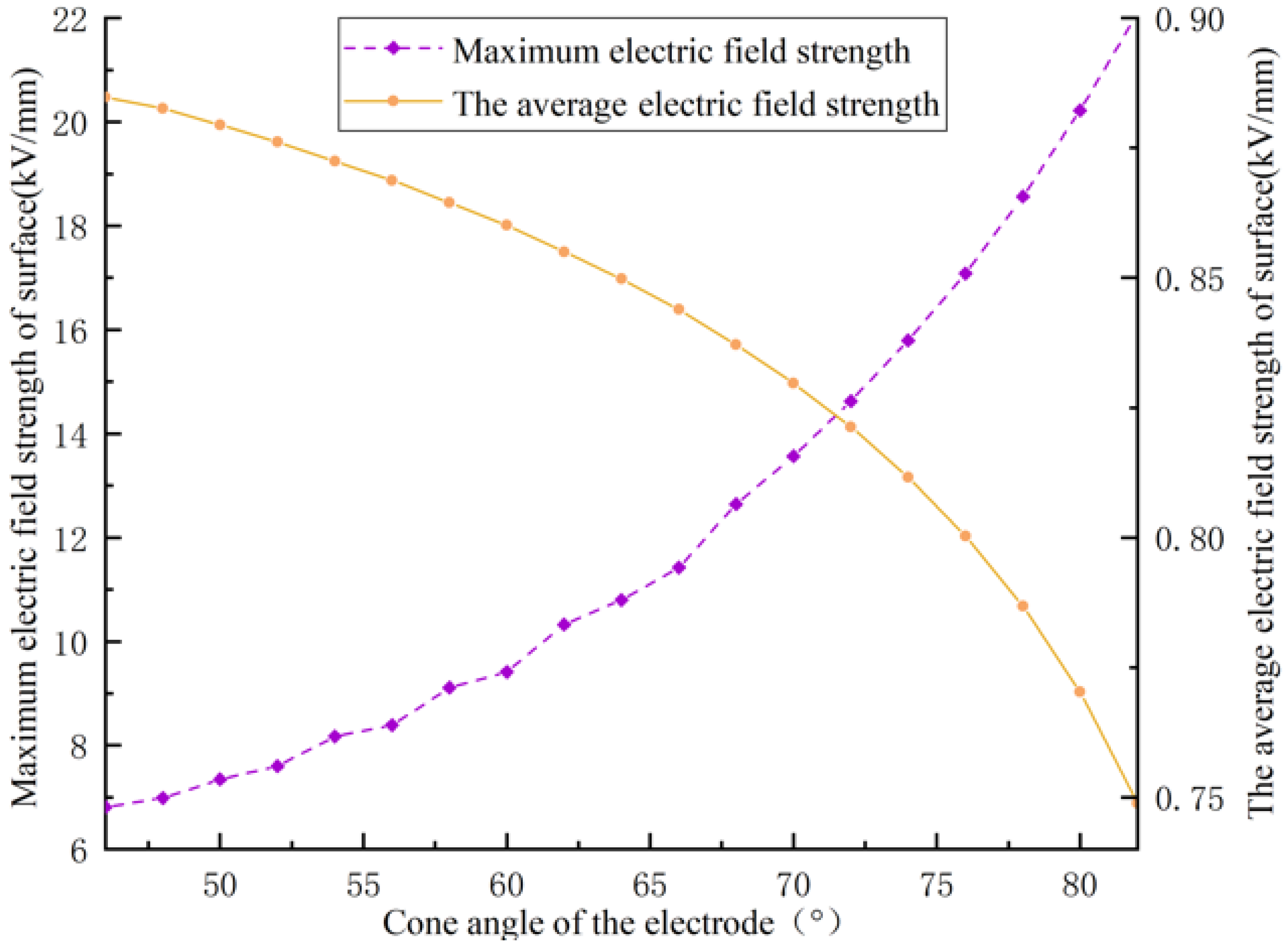
The influence on EPB of an electrode with a cone-horizontal surface angle of 46°, step length of 2°, and maximum taper of 82° was analyzed. The granite composition, electrode spacing and electrical parameters remained constant. Curves of the maximum and average electric field intensities on the granite surface with various electrode shapes are shown in Figure 11. It is shown that the maximum electric field intensity on the granite surface increases with increases of the angle. The granite was composed of potassium feldspar, plagioclase, quartz, and biotite. With an angle of 82°, the maximum electric field intensity on the granite surface is 22.09 kV/mm. However, the average electric field intensity of the surface decreases with increases of angle.
Kusaiynov et al. [11] designed an electrode drill with a zigzag shape that can increase the electric field strength without changing the input. The distribution of the electric field in granite during EPB is shown in Figure 12. It can be seen that the maximum electric field intensity in granite increases with increases of angle, but the extent of the increase is low. At the same time, the electrode shape has little effect on the internal electric field depth.
3.4. Influence of Electrical Parameters on EPB
The effects of discharge voltage, discharge waveform and discharge frequency on electric pulse drilling were simulated and analyzed. The discharge waveform is related to the parameters of the electric circuit such as its capacitance. Finally, the energy injected into the granite was measured to evaluate the effect of EPB in granite. With charging voltages of U1 = 50 kV, U2 = 80 kV, and U3 = 100 kV, the equivalent discharge voltage waveform, discharge current waveform, power waveform and energy waveform injected into the plasma channel were determined (Figure 13). This waveform verifies the changes in voltage, current, and energy in the three stages of granite fragmentation during EPB. In the second stage, the voltage on the high-voltage electrode decreases rapidly, and the current in the circuit increases rapidly. In this stage, the power and energy of the plasma channel increase the fastest. The energy injected into the plasma channel is converted into shockwave energy and channel heating energy. This stage is the plasma channel expansion stage and is the main stage in which the energy in the capacitor is converted into shockwave energy [25].
The maximum energy storage capacity, the maximum power and energy injected into the granite plasma channel and the energy conversion rate in Table 2 can be obtained and extrapolated from Figure 13. It can be concluded that the power and energy injected into the granite plasma channel increase with increases in the charging voltage of the high-voltage electric pulse power supply system. Thus, the granite is easier to break during drilling. However, the energy conversion efficiency of the plasma channel injected into the granite decreases. The primary discharge time of the waveform is within 30 us, and the ratio of primary discharge time to discharge cycle time is small. The energy injected into the plasma channel increases with increases in the discharge frequency per unit time, and the granite is easier to break. The total energy injected into the plasma channel increases with increases in discharge cycle number, and the granite is more easily broken.
When the capacitor values of equivalent circuit are C1 = 8 uF, C2 = 16 uF, and C3 = 64 uF, the equivalent discharge voltage waveform, discharge current waveform, power waveform and energy waveform injected into the plasma channel are as shown in Figure 14. It can be seen that the capacitance value has a great influence on the output voltage and current waveform. The pulse width of the discharge voltage and current increases with increases in capacitance. The power and energy injected into the plasma channel increase simultaneously in a single discharge. However, as the capacitance value increases, the charge and discharge time increase, and the discharge rate decreases.
4. Conclusions
Hard granite was used to investigate EPB in this paper, allowing a mathematical model of high-voltage electro pulse discharge in rock to be established. A numerical simulation model of EPB was established simultaneously. The influences of continuously varied granite composition, discharge parameters, electrode shape and electrode spacing on EPB were simulated and analyzed. The relationships between various factors and EPB in granite were obtained from the simulations. The following conclusions can be drawn:
(1) The distribution of electric field intensity is not uniform with different rock compositions. The more types of rock composition, the greater the difference in the electrical properties of each component, and the greater the electric field intensity during EPB. The electric field intensity is greater closer to the boundaries of different rock components and to the electrode. Thus, in hard rock drilling, the drilling effect of EPB is good at more rock compositions and different electrical properties.
(2) The ability and depth to break granite are weakened, but the radial breaking range of granite is increased with increased electrode spacing. When the electrode spacing is reduced by half, the maximum electric field intensity on the granite surface is increased by 1.7 times, in theory. Under the premises of ensuring breakage range and insulation, a small electrode spacing should be selected to improve rock breaking efficiency and breaking depth.
(3) The ability of EPB to break granite is enhanced with an increase in the angle between the conical surface of the high-voltage electrode and the granite plane, but this has little effect on drilling range and depth. A zigzag-shaped electrode can be used to increase the electric field strength in granite [11], achieve the objective of improving crushing efficiency.
(4) As the voltage increases, the granite breaking ability of EPB becomes stronger, but the energy conversion efficiency decreases. With increases in capacitance, the granite breaking ability of EPB becomes stronger, but the charging and discharging rate and discharging frequency are lower. The primary discharge time of the waveform is very short, and the duty ratio of pulse power supply is small. Energy consumption of efficient EPB can be reduced by increasing frequency of pulse power supply or the number of discharges.
This study of the influences on high-voltage EPB of granite is of significance for improving rock breaking efficiency, reducing energy losses, designing electrode drill bits and selecting drilling process parameters. The mathematical model and EPB numerical simulation model used in this study is helpful in analyzing the influence of various factors on EPB under various conditions, including extreme ones. The results of this paper allow better optimization of the electric pulse bit and drilling parameters according to the required drilling rate, hole diameter and other practical specifications. It will inform further theoretical and experimental study of EPB and rock fracture mechanics.
5. Patents
Changping Li; Xianfeng Tan; Longchen Duan; et al. An Electrode drill bit owned multi electrode pair and experimental device of electrical breaking. CHN.Patent 201820098015.X, 22 January 2018.
Longchen Duan; Changping Li; Xianfeng Tan; et al. An electric pulse drill bit of rock breaking and its experimental device. CHN.Patent 201820085807.3, 18 January 2018.
Author Contributions
Conceptualization, L.D. and V.C.; Data curation, C.L. and S.T.; Formal analysis, C.L. and S.T.; Methodology, C.L.; Project administration, L.D.; Software, C.L.; Writing–original draft, C.L.
Acknowledgments
This work was supported by the National Natural Science Foundation of China (41672364; 41602373) and the Innovation Fund of Petro-China (2016D-5007-0307).
Conflicts of Interest
The authors declare no conflict of interest.
Nomenclature
| L | Inductive inductance, H |
| i | Current in the loop, A |
| Rz | Circuit resistance, Ω |
| Rtd | Resistance of plasma channel, Ω |
| Uc | Instantaneous voltage of capacitor, V |
| C | Energy storage capacitance, F |
| U0 | Charge voltage, V |
| Ktd | Resistance coefficient, V·S1/2/m |
| ltd | Length of the plasma channel, m |
| Ptd | Power injected into the plasma channel, W |
| Wtd | Energy injected into the plasma channel, J |
| τ | Discharge relaxation time of the rock, s |
| T | External discharge time, s |
| ε0 | Vacuum permittivity, F/m |
| εr | Relative permittivity |
| P | Polarization intensity vector, C/m2 |
| ρ | Electric field density in space, C/m3 |
References
- Schiegg, H.O.; Rødland, A.; Zhu, G.Z.; Yuen, D. Electro-Pulse-Boring (EPB): Novel Super-Deep Drilling Technology for Low Cost Electricity. J. Earth Sci. 2015, 26, 37–46. [Google Scholar] [CrossRef]
- Yan, T.; Du, J.Y.; Li, W.; Bi, X.L.; Yao, S.L. Synthesizing Comment on Efficient Rock Fragmentation Method in Frontier Drilling Technology. Oil Field Equip. 2012, 41, 50–55. [Google Scholar]
- Ge, Z.L.; Deng, K.; Lu, Y.Y.; Cheng, L.A.; Zuo, S.J.; Tian, X.D. A novel method for borehole blockage removal and experimental study on a hydraulic self-propelled nozzle in underground coal mines. Energies 2016, 9, 698. [Google Scholar] [CrossRef]
- Lam, S.S.; Chase, A.H. A review on waste to energy processes using microwave pyrolysis. Energies 2012, 5, 4209–4232. [Google Scholar] [CrossRef]
- Biela, J.; Marxgut, C.; Bortis, D.; Kolar, J.W. Solid state modulator for plasma channel drilling. IEEE Trans. Dielectr. Electr. Insul. 2009, 16, 1093–1099. [Google Scholar] [CrossRef]
- Cho, S.H.; Cheong, S.S.; Yokota, M.; Kaneko, K. The dynamic fracture process in rocks under high-voltage pulse fragmentation. Rock Mech. Rock Eng. 2016, 49, 3841–3853. [Google Scholar] [CrossRef]
- Andres, U. Electrical disintegration of rock. Miner. Proc. Extract. Metullargy Rev. 1995, 14, 87–110. [Google Scholar] [CrossRef]
- Fujita, T.; Yoshimi, I.; Shibayama, A.; Miyazaki, K.; Abe, K.; Sato, M.; Yen, W.T.; Svoboda, S.J. Crushing and liberation of materials by electrical disintegration. EJMP EP (Eur. J. Miner. Process. Environ. Prot.) 2001, 1, 113–122. [Google Scholar]
- Ito, M.; Owada, S.; Nishimura, T.; Ota, T. Experimental study of coal liberation: Electrical disintegration versus roll-crusher comminution. Int. J. Miner. Process. 2009, 92, 7–14. [Google Scholar] [CrossRef]
- Timoshkin, I.V.; Mackersie, J.W.; Macgregor, S.J. Plasma channel microhole drilling technology. In Proceedings of the IEEE International Pulsed Power Conference, Dallas, TX, USA, 15–18 June 2003; pp. 1336–1339. [Google Scholar]
- Kusaiynov, K.; Nussupbekov, B.R.; Shuyushbayeva, N.N.; Tanasheva, N.K.; Shaimerdenova, K.M.; Khassenov, A.K. On electric-pulse well drilling and breaking of solids. Tech. Phys. 2017, 62, 867–870. [Google Scholar] [CrossRef]
- Inoue, H.; Lisitsyn, I.V.; Akiyama, H. Drilling of hard rocks by pulsed power. IEEE Electr. Insul. Mag. 2000, 16, 19–25. [Google Scholar] [CrossRef]
- Bluhm, H.; Frey, W.; Giese, H.; Hoppe, P.; Schultheiss, C.; Strassner, R. Application of pulsed HV discharges to material fragmentation and recycling. IEEE Trans. Dielectr. Electr. Insul. 2000, 7, 625–636. [Google Scholar] [CrossRef]
- Vizir, V.A.; Kovalchuk, B.M.; Kharlov, A.V.; Kumpyak, E.V.; Chervyakov, V.V.; Shubkin, N.G.; Tsoy, N.V.; Zorin, V.B.; Kiselev, V.N.; Chupin, V.V. High-Voltage Pulsed Generator for Dynamic Fragmentation of Rocks. Rev. Sci. Instrum. 2010, 81, 308–311. [Google Scholar]
- He, M.B.; Jiang, J.B.; Huang, G.L.; Liu, J.; Li, C.Z. Disintegration of rocks based on magnetically isolated high voltage discharge. Rev. Sci. Instrum. 2013, 84, 61–70. [Google Scholar] [CrossRef] [PubMed]
- Ji, N.Y.; Pei, Y.L.; Yan, K.P.; Liu, C.G.; Zhang, Z.C. Development of High-voltage Pulse-transmission Electric Cable for Plasma Drill. Mach. Electron. 2012, 8, 7–10. [Google Scholar]
- Zhang, Z.C. Rock Fragmentation by Pulsed High Voltage Discharge and Drilling Equipment Development. Ph.D. Thesis, Zhejiang University, Hangzhou, China, 6 June 2013. [Google Scholar]
- Kurets, V.I.; Lopatin, V.V.; Noskov, M.D. Influence of local heterogeneities on discharge channel trajectory at electric pulse destruction of materials. J. Min. Sci. 2000, 36, 268–274. [Google Scholar] [CrossRef]
- Boev, S.; Vajov, V.; Jgun, D.; Levchenko, B.; Muratov, V.; Adam, A.; Uemura, K. Destruction of granite and concrete in water with pulse electric discharges. In Proceedings of the IEEE International Pulsed Power Conference, Columbia, MO, USA, 27–30 June 1999; pp. 1369–1371. [Google Scholar]
- Wang, E.; Shi, F.N.; Manlapig, E. Experimental and numerical studies of selective fragmentation of mineral ores in electrical comminution. Int. J. Miner. Process. 2012, 112, 30–36. [Google Scholar] [CrossRef]
- Andres, U.; Timoshkin, I.; Soloviev, M. Energy consumption and liberation of minerals in explosive electrical breakdown of ores. Miner. Process. Extract. Metall. 2013, 110, 149–157. [Google Scholar] [CrossRef]
- Van der Wielen, K.P.; Pascoe, R.; Weh, A.; Wall, F.; Rollinson, G. The influence of equipment settings and rock properties on high voltage breakage. Miner. Eng. 2013, 46, 100–111. [Google Scholar] [CrossRef]
- Lisitsyn, I.V.; Inoue, H.; Nishizawa, I.; Katsuki, S.; Akiyama, H. Breakdown and destruction of heterogeneous solid dielectrics by high voltage pulses. J. Appl. Phys. 1998, 84, 6262–6267. [Google Scholar] [CrossRef]
- Burkin, V.V.; Kuznetsova, N.S.; Lopatin, V.V. Dynamics of electro burst in solids: I. Power characteristics of electro burst. J. Phys. D Appl. Phys. 2009, 42, 235–241. [Google Scholar] [CrossRef]
- Burkin, V.V.; Kuznetsova, N.S.; Lopatin, V.V. Dynamics of electro burst in solids: II. Characteristics of wave process. J. Phys. D Appl. Phys. 2009, 42, 242–248. [Google Scholar] [CrossRef]
- Yan, F.Z.; Lin, B.Q.; Zhu, C.J.; Guo, C.; Zhou, Y.; Zou, Q.L.; Liu, T. Using high-voltage electrical pulses to crush coal in an air environment: An experimental study. Powder Tech. 2016, 298, 50–56. [Google Scholar] [CrossRef]
- Kao, K.C. New theory of electrical discharge and breakdown in low-mobility condensed insulators. J. Appl. Phys. 1984, 55, 752–755. [Google Scholar] [CrossRef]
- Mohammada, R.S.; Bahram, R.; Mehdi, I.; Hasan, R.M. Numerical simulation of high voltage electric pulse comminution of phosphate ore. Int. J. Min. Sci. Tech. 2015, 25, 473–478. [Google Scholar]
Figure 1.
Two types of high-voltage electro pulse rock breaking: (a) electrohydraulic rock breaking; (b) electro pulse rock breaking.
Figure 1.
Two types of high-voltage electro pulse rock breaking: (a) electrohydraulic rock breaking; (b) electro pulse rock breaking.

Figure 2.
Relationship between breakdown field strength of different media and rising time of pulse voltage.
Figure 2.
Relationship between breakdown field strength of different media and rising time of pulse voltage.
Figure 3.
Structure and drilling principle diagram of an EPB system.

Figure 4.
Equivalent circuit of high-voltage electro pulse breakdown: 1–water medium, 2-rock, C–storage capacitor, S–spark switches, Rz–circuit resistance, L–inductive inductance, Rtd–resistance of plasma channel.
Figure 4.
Equivalent circuit of high-voltage electro pulse breakdown: 1–water medium, 2-rock, C–storage capacitor, S–spark switches, Rz–circuit resistance, L–inductive inductance, Rtd–resistance of plasma channel.

Figure 5.
Rock sample from Harizha.

Figure 6.
Mineral slice from Harizha.
Figure 7.
EPB simulation model.

Figure 8.
Simulation results of the influence of granite composition on EPB: (a) 1–potassium feldspar, 2–quartz, 3–plagioclase, 4–biotite, (b) 1–potassium feldspar, 2–quartz, 3–plagioclase, 5–magnetite, (c) 1–potassium feldspar, 2–quartz, 4–biotite, (d) 1–potassium feldspar, 2–quartz.
Figure 8.
Simulation results of the influence of granite composition on EPB: (a) 1–potassium feldspar, 2–quartz, 3–plagioclase, 4–biotite, (b) 1–potassium feldspar, 2–quartz, 3–plagioclase, 5–magnetite, (c) 1–potassium feldspar, 2–quartz, 4–biotite, (d) 1–potassium feldspar, 2–quartz.

Figure 9.
Relationships between electrode spacing and (a) maximum and (b) average electric field intensity.
Figure 9.
Relationships between electrode spacing and (a) maximum and (b) average electric field intensity.
Figure 10.
Results of the simulation of the influence of electrode spacing on the electric field distribution in the granite interior.
Figure 10.
Results of the simulation of the influence of electrode spacing on the electric field distribution in the granite interior.

Figure 11.
Simulation of maximum and average electric field intensities according to electrode shape.
Figure 11.
Simulation of maximum and average electric field intensities according to electrode shape.

Figure 12.
Simulation results of the influence of electrode shape on the electric field distribution within granite.
Figure 12.
Simulation results of the influence of electrode shape on the electric field distribution within granite.
Figure 13.
(a) Voltage waveform of equivalent circuit, (b) current waveform, (c) power waveform of injection into plasma channel, (d) energy waveform. L = 5 uH, C = 8 uF, U (kV): U1 = 50, U2 = 80, U3 = 100.
Figure 13.
(a) Voltage waveform of equivalent circuit, (b) current waveform, (c) power waveform of injection into plasma channel, (d) energy waveform. L = 5 uH, C = 8 uF, U (kV): U1 = 50, U2 = 80, U3 = 100.
Figure 14.
(a) Voltage waveform of equivalent circuit, (b) current waveform, (c) power waveform of injection into plasma channel, (d) energy waveform, U = 50 kV, L = 5 uH, C (uF): C1 = 8, C2 = 16, C3 = 64.
Figure 14.
(a) Voltage waveform of equivalent circuit, (b) current waveform, (c) power waveform of injection into plasma channel, (d) energy waveform, U = 50 kV, L = 5 uH, C (uF): C1 = 8, C2 = 16, C3 = 64.

Table 1.
Properties of the materials used in the simulation model.
| Material | Electrical Permittivity | Material | Electrical Permittivity |
|---|---|---|---|
| Water | 80 [28] | Potassium feldspar | 6.2 |
| Plagioclase | 6.91 | Quartz | 6.53 |
| Biotite | 9.28 | Magnetite | 65 |
Table 2.
Maximum energy storage capacity, the injected maximum power and energy, and the energy conversion rate with charging voltages of U1 = 50 kV, U2 = 80 kV, U3 = 100 kV.
Table 2.
Maximum energy storage capacity, the injected maximum power and energy, and the energy conversion rate with charging voltages of U1 = 50 kV, U2 = 80 kV, U3 = 100 kV.
| Charging Voltages | Maximum Energy Storage Capacity | Injected Maximum Power | Injected Maximum Power | Energy Conversion Rate |
|---|---|---|---|---|
| 50 kV | 10 kJ | 241.5 MW | 3.2 kJ | 32% |
| 80 kV | 25.6 kJ | 462.5 MW | 5.5 kJ | 21% |
| 100 kV | 40 kJ | 621.1 MW | 7.1 kJ | 18% |
© 2018 by the authors. Licensee MDPI, Basel, Switzerland. This article is an open access article distributed under the terms and conditions of the Creative Commons Attribution (CC BY) license (http://creativecommons.org/licenses/by/4.0/).
Share and Cite
MDPI and ACS Style
Li, C.; Duan, L.; Tan, S.; Chikhotkin, V. Influences on High-Voltage Electro Pulse Boring in Granite. Energies 2018, 11, 2461. https://doi.org/10.3390/en11092461
AMA Style
Li C, Duan L, Tan S, Chikhotkin V. Influences on High-Voltage Electro Pulse Boring in Granite. Energies. 2018; 11(9):2461. https://doi.org/10.3390/en11092461
Chicago/Turabian StyleLi, Changping, Longchen Duan, Songcheng Tan, and Victor Chikhotkin. 2018. "Influences on High-Voltage Electro Pulse Boring in Granite" Energies 11, no. 9: 2461. https://doi.org/10.3390/en11092461
Note that from the first issue of 2016, this journal uses article numbers instead of page numbers. See further details here.