Article

Exploring the Electro-Thermal Parameters of Reliable Power Modules: Insulated Gate Bipolar Transistor Junction and Case Temperature

1
State Key Laboratory of Reliability and Intelligence of Electrical Equipment, Hebei University of Technology, Tianjin 300130, China
2
Key Laboratory of Electromagnetic Field and Electrical Apparatus Reliability of Hebei Province, Hebei University of Technology, Tianjin 300130, China
3
Institute of Innovation and Circular Economy, Asia University, Taichung 41354, Taiwan
4
School of Business, Dalian University of Technology, Panjin 124221, China
*
Authors to whom correspondence should be addressed.
Energies 2018, 11(9), 2371; https://doi.org/10.3390/en11092371
Submission received: 12 July 2018 / Revised: 4 August 2018 / Accepted: 3 September 2018 / Published: 8 September 2018

Abstract

:
In the exploration of new energy sources and the search for a path to sustainable development the reliable operation of wind turbines is of great importance to the stability of power systems. To ensure the stable and reliable operation of the Insulated Gate Bipolar Transistor (IGBT) power module, in this work the influence of changes with aging of different electro-thermal parameters on the junction temperature and the case temperature was studied. Firstly, power thermal cycling tests were performed on the IGBT power module, and the I-V characteristic curve, switching loss and transient thermal impedance are recorded every 1000 power cycles, and then the electrical parameters (saturation voltage drop and switching loss) and the thermal parameters (junction-to-case thermal resistance) of the IGBT are obtained under different aging states. The obtained electro-thermal parameters are substituted into the established electro-thermal coupling model to obtain the junction temperature and the case temperature under different aging states. The degrees of influence of these electro-thermal parameters on the junction temperature and case temperature under different aging states are analyzed by the single variable method. The results show that the changes of the electro-thermal parameters under different aging states affects the junction temperature and the case temperature as follows: (1) Compared with other parameters, the transient thermal impedance has the greatest influence on the junction temperature, which is 60.1%. (2) Compared with other parameters, the switching loss has the greatest influence on the case temperature, which is 79.8%. The result provides a novel method for the junction temperature calculation model and lays a foundation for evaluating the aging state by using the case temperature, which has important theoretical and practical significance for the stable operation of power electronic systems.

1. Introduction

At present, scientists all over the world are striving to explore new energy sources and seeking a path to sustainable development. Constantly expanding the scope of application of new energy is an important means to promote the sustainable development of the entire society [1]. The core of energy efficient utilization is the efficient control and conversion of various energy forms [2]. New energy sources such as wind energy are being widely used in the field of electrical energy conversion, where wind turbines often work in harsh environments and are easily affected by the performance of their subsystems. As the most important subsystem, the power conversion device causes the wind turbine to stop working in case of failure [3]. The Insulated Gate Bipolar Transistor (IGBT) power module is the most important device in the power electronics subsystem, whose working ability gradually decreases with as it ages under practical working conditions [4]. Therefore, how to accurately evaluate the aging state of the IGBT power module to ensure the stable operation of the wind turbines is an important study topic [5,6].
In the literature, Bo et al. [7] found that the failures of IGBT power module are mainly caused by thermal mechanical stress caused by temperature fluctuations, and the reliability of the power module is closely related to the junction temperature. In the assessment of the aging state of IGBT, the aging state of the power module is often evaluated by monitoring the changes of certain parameters, which include the saturation voltage drop, junction-to-case thermal resistance, switching time, gate signal, and junction temperature [8]. Ji et al. [9] proposed a method to reflect bonding wire failure by monitoring the change of saturation voltage drop, which is one of the most common package failures. However, the saturation voltage drop varies with the aging of the IGBT until the failure of IGBT, and while this method can monitor the failure of the IGBT, it cannot fully monitor the aging state of the IGBT power module. Oukaour et al. [10] studied the change law of IGBT saturation voltage drop with module aging through power thermal cycling tests, but they did not consider the influence of junction temperature and collector current variation on the saturation voltage drop, therefore, the error between the evaluated aging state and the actual aging state was large.
In the practical application of IGBT power modules, IGBTs fail when they work for a long time, and the fault reasons mainly include the bonding wires falling off and solder layer fatigue, and these faults are caused by the aging of the IGBT power module [11]. The aging state of the power module is mainly evaluated by using electrical parameters and thermal parameters [12]. For example, the IGBT saturation voltage drop is commonly used to evaluate the case of bonding wires falling off [13]. The junction-to-case thermal resistance is often used to evaluate the state of the solder layer fatigue [14]. Whether the saturation voltage drop or the junction-to-case thermal resistance is used to evaluate the aging state of the IGBT power module, the junction temperature will be used. The commonly used methods of junction temperature measurement and calculation include experimental measurement [15], iterations and numerical simulation, and simulation analysis [16]. The proposed methods neither achieve accurate online measurements nor do they consider the influence of different degrees of aging of the IGBT power module on junction temperature.
This study proposes a simple and convenient to use the case temperature to evaluate the aging state of the IGBT compared to the measurement of electrical parameters. Wang et al. [17] used the Cauer thermal network model to monitor the temperature change, but it is difficult to obtain the parameters of the model. Astigarrag et al. [18] performed power thermal cycling tests on different types of parameter and showed that the case temperature, the collector current and the collector-to-emitter voltage can all be used as failure precursors for prediction and health monitoring. Hence, this study considers the case temperature as the precursor of the fault, which does not take account of the influence of the parameters, such as the collector-to-emitter voltage on the case temperature, so the prediction results have a certain error.
The prior proposed methods do not fully consider all the influencing factors by using the on-state voltage drop or monitoring the junction temperature and the case temperature to evaluate the aging state. With the aging of the power module, the structure of the power module and the electro-thermal parameters of the junction temperature calculation model are constantly changing, therefore, this is necessary to study the influence of the electro-thermal parameters on the junction temperature under different aging states. This study not only analyzes the influence of switching loss and thermal impedance of IGBT on the junction temperature and the case temperature, but also analyzes the influence of threshold voltage and on-resistance of IGBT on the junction temperature and the case temperature. This study makes the simplification of the junction temperature calculation model more theoretically significant, at the same time; the case temperature can more intuitively reflect the changes of the electro-thermal parameters.
This study has the following goals: (1) Using the principle of electro-thermal analogy, combing the electrical model with the Foster thermal network model to establish an electro-thermal coupling model to calculate the junction temperature and the case temperature of the IGBT. (2) Analyzing and comparing the influence of different electro-thermal parameters on the junction temperature and case temperature, which can simplify the junction temperature calculation model and provide a new idea for further studying the relationship between case temperature and switching loss of IGBT. The rest of this study is organized as follows: Section 2 describes the process of the electro-thermal coupling model. Section 3 describes the test process. Section 4 analyzes the test results, the junction temperature and the case temperature under different aging state are calculated, and the degrees of influence of different electro-thermal parameters on the junction temperature and case temperature is calculated. Section 5 summarizes the implications of this study with spotlights on the research significance and popularization of this research. Finally, Section 6 discusses the conclusion.

2. Model Establishment

This study describes the process of establishing an electro-thermal coupling model.

2.1. The Electrical Model

The heat sources in a IGBT power module are mainly the IGBT chips and free-wheeling diode (FWD) chips. However, the power loss generated by the IGBT chips accounts for more than 95% of the total loss. Therefore, it can be roughly assumed that the total loss of power module is generated by the IGBT chips, that is, these chips can be used as the heat source of the entire module [19].
The establishing process of an electro-thermal coupling model is illustrated in a three-phase inverter using the Sinusoidal Pulse Width Modulation (SPWM), the three-phase inverter is shown in Figure 1. The switching frequency is denoted by f s w , the frequency of modulated wave is denoted by f, and the load is the RL type load. The modulated wave is denoted by Ur, and the duty cycle of the IGBT is δ ( t ) = 1 + U r 2 .
The specific type of IGBT power module used in the test is a MMG75S120B6HN (MACMIC, ChangZhou, China), which is widely used in practical engineering applications because it is not only a key component in wind turbines, but it can also be applied to the motor drive circuit in new energy vehicles, and the inverter circuits of photovoltaic power generation systems.
The IGBT power loss mainly includes conduction loss and switching loss, and its calculation Equation is expressed as follows:
P = P c o n + P s w ,
where P is the IGBT power loss, Pcon is the IGBT conduction loss, and Psw is the IGBT switching loss. The equation of Pcon is expressed as follows [20,21]:
P c o n = V c e ( T j ) i c δ ( t ) ,
where, Vce is the collector-to-emitter voltage and also known as the saturation voltage drop, Tj is the junction temperature of the IGBT, ic is the collector current, δ is the duty cycle.
The I-V characteristic curve is shown in Figure 2. The calculation equation of Vce can be obtained by linear fitting the characteristic curve and the equation of Vce is as follows:
V c e = V c e o + i c r c e ,
where, Vceo is the IGBT threshold voltage and rce is the IGBT on-resistance.
In Figure 2, the solid line shows the I-V characteristic of the IGBT at 298.15 K, and the dotted line shows the corresponding fitting curve. Both V c e o and r c e change linearly with temperature, which can be approximated by the following equations:
V c e o = V c e o _ 298.15 K + K V c e o ( T j 298.15 ) ,
r c e = r c e _ 298.15 K + K r c e ( T j 298.15 ) ,
where, V c e o _ 298.15 K and r c e _ 298.15 K are the threshold voltage and on-resistance at 298.15 K, Tj is the junction temperature, K V c e o and K r c e are the temperature coefficients of the corresponding parameters, which is the slope of the linear fitting curve I-V characteristic curve at different temperatures. Therefore, the condition loss Pcon can be expressed as follows:
P c o n = ( V c e o _ 298.15 K + K V c e o ( T j _ I 298.15 ) ) i c δ ( t ) + ( r c e _ 298.15 K + K r c e ( T j _ I 298.15 ) ) i c 2 δ ( t ) ,
During a certain switching cycle, the mean turn-on loss P o n and the mean turn-off loss P o f f constitute the switching loss P s w :
P s w = P o n + P o f f ,
P o n = f s w E o n K i K V d c K R g _ o n K T j ,
P o f f = f s w E o f f K i K V d c K R g _ o f f K T j ,
where, fsw is the switching frequency, Eon and Eoff are turn-on loss and turn-off loss at rating condition, which can be obtained according to the device manual. Ki is the current coefficient, K V d c is the voltage coefficient, K R g _ o n and K R g _ o f f are the influence coefficients of IGBT gate resistance Rg on Eon and Eoff, Rg = 10 Ω is used, The temperature coefficient K T j can be expressed as K T j = 1 + 0.03·(Tj − 398.15):
K V d c = V d c V N ,
K i = i c I N ,
where, Vdc is the DC side voltage of the inverter, VN is the rated voltage of the IGBT, IN is the rated current of the IGBT.
Using the equations, the electrical model is obtained, which is shown in Equation (12).
P = ( V c e o _ 298.15 K + K V c e o ( T j 298.15 ) ) i c δ ( t ) + ( r c e _ 298.15 K + K r c e ( T j _ I 298.15 ) ) i c 2 δ ( t ) + f s w E o n V d c V N i c I N K R g _ o n ( 1 + 0.03 ( T j 398.15 ) ) + f s w E o f f V d c V N i c I N K R g _ o f f ( 1 + 0.03 ( T j 398.15 ) )

2.2. The Foster Thermal Model

The distance between the MMG75S120B6HN module IGBT chip and the FWD chip is 6.4 mm, so the thermal coupling between the chips can be ignored [22]. The heat generated by the FWD chip has little effect on the rise of the case temperature, and the heat production of the FWD chip is basically unchanged under different aging states [23]. In order to simplify the analysis of the effect of electro-thermal parameters on the junction temperature and case temperature, this study only considers the effect of heat generated by IGBT chip, which has no influence on the accuracy of the result. This study uses a fourth-order Foster thermal network model to simulate the heat dissipation process of the power module to meet the requirements of accuracy and speed. The package structure diagram of the power module and the thermal network model are shown in Figure 3.
Figure 3 shows Z t h , j c and Z t h , c a represented the equivalent impedance from the IGBT chip to the case and the equivalent impedance from the case to the environment. Tc represents the case temperature of the module, and Ta represents the ambient temperature. The equivalent thermal impedance can be obtained by fitting the transient thermal resistance with Equation (13):
Z t h = i = 1 n R i ( 1 e t ( R i C i ) )
where Z t h is the equivalent thermal impedance, n is the thermal network order, generally the order is 4, Ri and Ci are the equivalent thermal resistance and the equivalent thermal capacity. In practical engineering applications, the transient thermal impedance is obtained using the YB-6911 thermal resistance test system of Xi’an Yibang Electronic Technology Co., Ltd (Xi’an, China).

3. Test Process

3.1. Acquisition of Electro-Thermal Parameters Under Different Aging States

The IGBT power module consists of materials of multiple layers with different thermal expansion coefficients. The power module often works in a high-frequency switching state, it gradually ages with the time, and the fatigue of solder layer and the falling off of bonding wire occur. Therefore, the electro-thermal parameters change with the aging of the IGBT. In order to further improve the accuracy of the electro-thermal coupling model, power thermal cycling tests of the IGBT are performed to simulate the electro-thermal parameters under different aging states. The degrees of influence of the electro-thermal parameters on the junction temperature and the case temperature are analyzed by putting the electro-thermal parameters of different aging states into the electro-thermal coupling model. The power module model for the power thermal cycling test is MMG75S120B6HN [24,25]. During the test, the gate-to-emitter voltage was maintained at Vge = 15 V, and a constant current of 75 A was applied to the power module using a programmable DC power supply. The IGBT power module was heated to 398.15 K when it is in the on state, and then it was cooled to 298.15 K (ambient temperature Ta) when it is in the off state. The temperature range is 298.15–398.15 K.
During the test process, the IGBT I-V characteristic, switching loss and transient thermal impedance were measured once per 1000 cycles at ambient temperature (298.15 K). According to the I-V characteristic curve, the threshold voltage V c e o and on-resistance r c e of the IGBT can be obtained under different aging states. The failure standard (the junction-to-case thermal resistance is 20% larger than that of the new device) [26], all IGBT power module failed after 6000 cycles of the test, the test results of the IGBT power cycling are recorded every 1000 times, and the results obtained are shown in the following Figure 4 and Figure 5 and Table 1, Table 2, Table 3 and Table 4.
Figure 5 indicated the junction-to-case thermal resistances under different aging states are shown in Table 3.
Using Equation (13), Z t h , j c increases with time t. As the operating time of the IGBT increases, mechanical hardening occurs inside the module, and the increase of the thermal stress causes cracks in the solder layer. As the IGBT ages further, the cracks continue to grow, resulting in chip bonding failure, and the phenomenon of bad contact between the different physical layers of the IGBT makes the junction-to-case thermal resistance increase with the aging of the IGBT, which leads to the continuous increase of Z t h , j c .
The saturation voltage drop of the IGBT is mainly determined by the threshold voltage and the on-resistance. According to the I-V characteristic curve, the threshold voltage and the on-resistance under different aging states are shown in Table 4.
Figure 4 and Figure 5 and Table 1, Table 2, Table 3 and Table 4 indicate that saturation voltage drop, switching loss and thermal resistance gradually increase, and the rate of increase increases with the further aging of the IGBT. When the power cycle reaches 6000 times, saturation voltage drop, switching loss, and thermal resistance are increased by 4.1%, 12.7%, 18.5%, and 22.8%, respectively, compared to the new device. The change of the electro-thermal parameters affect the junction temperature and the case temperature; therefore, it is necessary to study the influence of the electro-thermal parameters under different aging states on the junction temperature and the case temperature.

3.2. Acquisition of IGBT Power Loss, Junction Temperature and Case Temperature Under Different Aging States

The electro-thermal coupling model is built, and the simulation parameters are shown in Table 5, where, M is the modulation ratio, t is the simulation time.
In the electro-thermal coupling model, the aged electrical parameters and thermal parameter are substituted into the model to obtain the power loss, junction temperature and case temperature under different cycle times. The results are shown in Figure 6, Figure 7 and Figure 8.
Figure 6, Figure 7 and Figure 8 presented the power loss, junction temperature, and case temperature of IGBT increase with the number of power thermal cycling tests as well as the gradual amplitude increase. Compared to the case temperature, the junction temperature of IGBT reaches a steady state early. When the power thermal cycling test reaches 6000 times, the junction temperature of steady state is 2.83 K higher than junction temperature of the new device, while the case temperature of steady state is 0.16 K higher than the case temperature of the new device.
In an actual industrial environment, the range of case temperature changes is small, which requires a high-precision temperature sensor to monitor the change of the case temperature and requires the temperature sensor to work stably. For example, a PICO temperature sensor, which has an error of less than 0.01 °C, can be used to monitor the changes of case temperature. It is mounted on the bottom of the IGBT module and then we can use the PicoLog data logging software to record, analyze and display the changes of case temperature.

4. Results Analysis

The single parameter method is used to study the influence of electro-thermal parameters on junction temperature and case temperature. Namely, by changing the above parameters of the IGBT at different power cycle times, the junction temperature and case temperature are calculated. The results obtained are shown in Figure 9 and Figure 10.
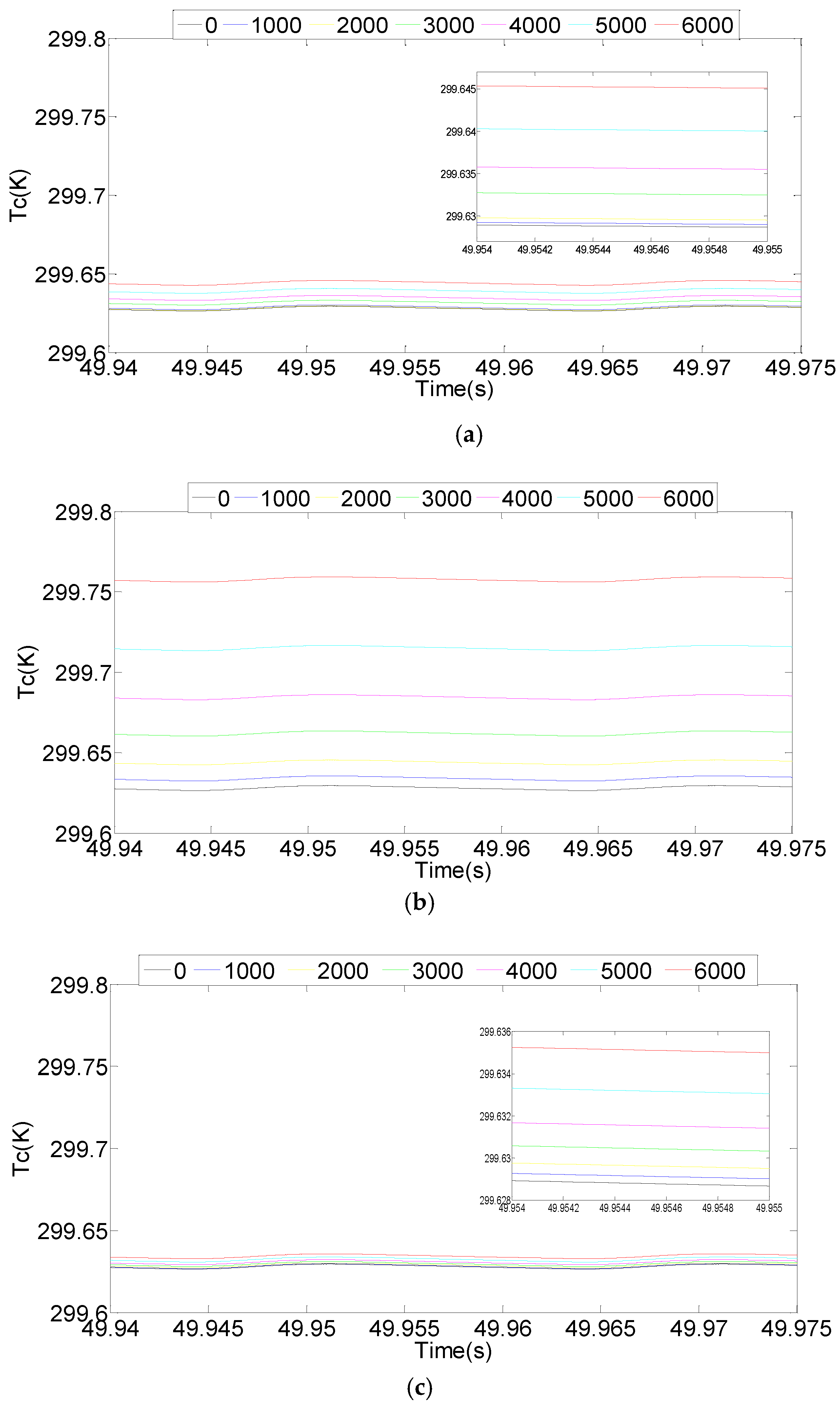
Comparing the subfigures (a), (b) and (c) in Figure 9, the threshold voltage and on-resistance have the least effect on the junction temperature, the switching loss has a larger effect on the junction temperature, and the thermal impedance has the largest effect on the junction temperature. Comparing subfigures (a), (b) and (c) in Figure 10, the thermal impedance has the least effect on case temperature, and the threshold voltage and on-resistance have small effect on case temperature, and the switching loss has the greatest effect on case temperature. The thermal impedance can directly reflect the fatigue degree of the solder layer, which has the greatest effect on the junction temperature and has the least effect on the case temperature.
The mean value of temperature fluctuation is taken as the reference value for analyzing the influence degree of electro-thermal parameters on the junction temperature and case temperature. The mean value of the junction temperature and case temperature under different aging states are expressed as T j m 0 , T j m 1 , , T j m 6 and T c m 0 , T c m 1 , , T c m 6 . The subscript numbers indicate the numbers of thousand cycles, all of them are shown in Table 6 and Table 7. The influence degrees are defined to express more intuitively the influence degree of the electro-thermal parameters on the junction temperature and case temperature:
C j V r = i = 1 6 T j m i V r 6 T j m o i = 1 6 T j m i 6 T j m o ,
where, C j V r is the influence degree on the junction temperature with the change of of V c e o and r c e , T j m i V r is the value of the junction temperature with the change of V c e o and r c e at different aging states:
C c V r = i = 1 6 T c m i V r 6 T c m o i = 1 6 T c m i 6 T c m o ,
where, CcVr is the influence degree on the case temperature with the change of Vceo and rce, TcmiVr is the value of the case temperature with the change of Vceo and rce at different aging states.
The influence degree of changing Eon and Eoff on junction temperature and case temperature, and the influence degree of changing Zth,jc on junction temperature and case temperature is obtained.
Table 6 and Table 7 show that different electro-thermal parameters have different degrees of influence on the junction temperature and case temperature of the IGBT power module. Taking the degree of influence on the junction temperature with the change of electro-thermal parameters as a reference, changing the thermal impedance the thermal impedance Zth,jc alone has the greatest influence on the junction temperature, and the degree of influence is C = 60.1%. Taking the degree of influence on the case temperature with the change of electro-thermal parameters as a reference, changing the switching losses Eon and Eoff have the greatest influence on the case temperature, and the influence degree is C = 79.8%. It can be considered that the main causes of the change in junction temperature is the parameter change of thermal impedance Zth,jc. This study considered that the main reason of the change in case temperature is the change of switching losses Eon and Eoff.

5. Implications

Traditional assessment models were used to evaluate the aging state of the power model in previous studies, which were evaluated using electrical or thermal parameters. Compared with previous studies, this study has two major contributions: (1) In this study is difficult to evaluate the whole aging state of the IGBT module by using the saturation voltage drop or the junction-to-case thermal resistance alone, and the above parameters are related to the junction temperature Tj, but the measurement of the junction temperature is difficult. This study analyzes the influence of the electro-thermal parameters on the junction temperature under different aging states, and provides data support for simplifying the junction temperature calculation model. This result improves the existing junction temperature calculation model and improves its prediction accuracy. (2) The influence of electro-thermal parameters on case temperature is analyzed. This lays a theoretical foundation for evaluating the aging states by using the case temperature and finding the relationship between case temperature and electro-thermal parameters. The case temperature can reflect the aging state of the IGBT, and the results provide a new way to establish the relationship between junction temperature and case temperature.
The failure of power modules is the main cause of power converter failure in wind turbines. The model established can simultaneously study the junction temperature and case temperature of the power modules, and the influence degree of different electro-thermal parameters on junction temperature and case temperature can be obtained. The junction temperature calculation and the aging states assessment are always solved to use the established model and analysis method in this study. The results are helpful to quickly find the cause of IGBT failure, which is beneficial to the reliable operation, and has a positive effect on the stability of power system and the effective use of new energy sources. The analysis method can be applied in other fields too. For example, in the field of fault diagnosis of power transformers, the influence of different parameters on power transformer faults can be analyzed according to the single parameter method, which is helpful to quickly find the cause of the power transformer failure. In the life prediction of relays, analyzing the influence of different parameters on the life of the relay is beneficial to remove redundant parameters and improve the accuracy of life predictions. Therefore, the results are of great significance for equipment transformation and industrial upgrading.

6. Conclusions

The safe and reliable operation of IGBT modules is conducive to the effective use of new energy sources like wind energy, which is of great significance for the sustainable development of society. This study analyzes the influence degree of electro-thermal parameters on the junction temperature and case temperature under different aging states based on electro-thermal coupling model. The main contributions are as follows:
(1)
Third item Power thermal cycling tests are carried out on a IGBT power module, and the obtained electro-thermal parameters of different aging states are brought into the electro-thermal coupling model to more accurately obtain the junction temperature and the case temperature under different aging states, which provides a method for simplification of the junction temperature calculation model and assessment of the aging state using the case temperature.
(2)
The same parameter has different influences on the junction temperature and case temperature. Among the electro-thermal parameters, the influence degree of threshold voltage and on-resistance on the junction temperature is 4.6%, and that on the case temperature is 11.4%. The influence degree of switching loss on junction temperature is 25.9%, and that on case temperature is 79.8%. The influence degree of thermal impedance on the junction temperature is 60.1%, and that on the case temperature is 6.1%. This confirms that the influence of a certain parameter on junction temperature and case temperature is different, and the difference in degree of influence is large.
(3)
The thermal impedance has the greatest influence on the junction temperature, and the switching loss has the greatest effect on the case temperature. The sum of linear superposition of the influence degrees of changing each single electro-thermal parameter on the junction temperature and the case temperature is not equal to the influence degree of changing all parameters on the junction temperature and the shell temperature.
(4)
The established IGBT model can combine the aging state, junction temperature and case temperature to provide technical support for further studying the relationship between junction temperature and case temperature under different aging states. The case temperature is easy to measure, which provides a convenient way to establish a mathematical calculation model that use case temperature to predict junction temperatures.

Author Contributions

Conceptualization, B.-Y.L. and G.-S.W.; Formal analysis, G.S.W. and Z.-G.L.; Methodology, M.-L.T. and K.-J.W.; Supervision, Z.-G.L.; Writing—Original draft, B.-Y.L. and G.S.W.; Writing—Review & editing, M.-L.T. and K.-J.W.

Funding

This research was funded by the National Natural Science Foundation of China [grant numbers 51475136] and the Key Project of Natural Science Foundation of Hebei Province [grant numbers E2017202284].

Acknowledgments

This work was supported by the National Natural Science Foundation of China [grant numbers 51475136] and the Key Project of Natural Science Foundation of Hebei Province [grant numbers E2017202284].

Conflicts of Interest

The authors declare no conflict of interest.

References

  1. Ludin, N.A.; Bakri, M.A.M.; Kamaruddin, N.; Sopian, K. Malaysian oil palm plantation sector: Exploiting renewable energy toward sustainability production. J. Clean. Prod. 2014, 65, 9–15. [Google Scholar] [CrossRef]
  2. Tseng, M.L.; Lin, R.J.; Tan, K.; Geng, Y.; Lim, M. Benchmarking eco-efficiency in green supply chain practices in uncertainty. Prod. Plan. Control. 2014, 25, 1079–1090. [Google Scholar] [CrossRef]
  3. Ribrant, J.; Bertling, L.M. Survey of failures in wind power systems with focus on Swedish wind power plants during 1997–2005. IEEE Trans. Energy Convers. 2007, 22, 167–173. [Google Scholar] [CrossRef]
  4. Lu, B.; Li, Y.; Wu, X.; Yang, Z. A review of recent advances in wind turbine condition monitoring and fault diagnosis. In Proceedings of the 2009 IEEE Power Electronics and Machines in Wind Applications, Lincoln, NE, USA, 24–26 June 2009; pp. 1–7. [Google Scholar]
  5. Yang, S.; Xiang, D.; Bryant, A. Condition monitoring for device reliability in power electronic converters: A review. IEEE Trans. Power Electron. 2011, 25, 2734–2752. [Google Scholar] [CrossRef]
  6. Li, L.L.; Wang, P.C.; Wang, C.H. Lifetime prediction model for electric vehicle IGBT modules under driving conditions. J. Chin. Inst. Eng. 2018, 41, 308–316. [Google Scholar] [CrossRef]
  7. Bo, T.; Wei, Q.; Ze, W. Monitoring IGBT’s Health Condition via Junction Temperature Variations. In Proceedings of the 2014 IEEE Applied Power Electronics Conference and Exposition—APEC 2014, Fort Worth, TX, USA, 16–20 March 2014; pp. 2550–2555. [Google Scholar]
  8. Xiang, D.W.; Li, R.; Peter, T. Monitoring solder fatigue in a power module using the rise of case-above-ambient temperature. IEEE Trans. Ind. Appl. 2011, 47, 2578–2591. [Google Scholar] [CrossRef]
  9. Ji, B.; Pickert, V.; Cao, W. In situ diagnostics and prognostics of wire bonding faults in IGBT modules for electric vehicle drives. IEEE Trans. Power Electron. 2013, 28, 5568–5577. [Google Scholar] [CrossRef]
  10. Oukaour, A.; Tala-Ighil, B.; Pouderoux, B.; Tounsi, M.; Bouarroudj-Berkani, M.; Lefebvre, S.; Boudart, B. Ageing defect detection on IGBT power modules by artificial training methods based on pattern recognition. Microelectron. Reliab. 2011, 51, 386–391. [Google Scholar] [CrossRef]
  11. Choi, U.M.; Blaabjerg, F.; Iannuzzo, F. Junction temperature estimation method for a 600V, 30A IGBT module during converter operation. Microelectron. Reliab. 2015, 55, 2022–2026. [Google Scholar] [CrossRef]
  12. Antonios, J.; Ginot, N.; Batard, C. A model reduction approach for constructing compact dynamic thermal models of IGBT-modules of inverters. Microelectron. J. 2012, 43, 345–352. [Google Scholar] [CrossRef]
  13. Smet, V.; Forest, F.; Huselstein, J.J. Ageing and failure modes of IGBT modules in high-temperature power cycling. IEEE Trans. Power Electron. 2011, 58, 4931–4941. [Google Scholar] [CrossRef]
  14. Pramod, G.; Szymon, B.; Stig, M.-N. A review on real time physical measurement techniques and their attempt to predict wear-out status of IGBT. In Proceedings of the 2013 15th European Conference on Power Electronics and Applications (EPE), Lille, France, 2–6 September 2013; pp. 1–10. [Google Scholar]
  15. Licht, T.; Speckels, R.; Thoben, M. Sintering technology used for interconnection of large areas: Potential and limitation for power modules. In Proceedings of the Integrated Power Systems (CIPS) 8th International Conference, Nuremberg, Germany, 16–18 March 2010; pp. 345–350. Available online: https://www.researchgate.net/profile/M_Thoben/publication/313637390_Sintering_technology_used_for_interconnection_of_large_areas_potential_and_limitation_for_power_modules/links/58a0d339a6fdccf5e96e8a33/Sintering-technology-used-for-interconnection-of-large-areas-potential-and-limitation-for-power-modules.pdf (accessed on 7 August 2018).
  16. Riedel, G.J.; Valov, M. Simultaneous testing of wirebond and solder fatigue in IGBT modules. In Proceedings of the CIPS 2014 8th International Conference on Integrated Power Electronics Systems, Nuremberg, Germany, 25–27 February 2014; pp. 1–5. [Google Scholar]
  17. Wang, Z.; Tian, B.; Qiao, W. Real-time aging monitoring for IGBT modules using case temperature. IEEE Trans. Power Electron. 2016, 63, 1168–1178. [Google Scholar] [CrossRef]
  18. Astigarraga, D.; Ibanez, F.M.; Galarza, A. Analysis of the Results of Accelerated Aging Tests in Insulated Gate Bipolar Transistors. IEEE Trans. Power Electron. 2016, 31, 7953–7962. [Google Scholar] [CrossRef]
  19. Hu, Z.; Du, M.; Wei, K. Real-time monitoring solder fatigue for IGBT modules using case temperatures. HKIE Trans. 2017, 24, 141–150. [Google Scholar] [CrossRef]
  20. Ghimire, P.; Pedersen, K.B.; Vega, A.R.D. A real time measurement of junction temperature variation in high power IGBT modules for wind power converter application. In Proceedings of the CIPS 2014 8th International Conference on Integrated Power Electronics Systems, Nuremberg, Germany, 25–27 February 2014; pp. 1–6. [Google Scholar]
  21. Dupont, L.; Avenas, Y. Preliminary evaluation of thermo-sensitive electrical parameters based on the forward voltage for online chip temperature measurements of IGBT devices. IEEE Trans. Ind. Appl. 2015, 51, 4688–4698. [Google Scholar] [CrossRef]
  22. Zhou, Z.; Kanniche, M.S.; Butcup, S.G. High-speed electro-thermal simulation model of inverter power modules for hybrid vehicles. IET Electr. Power Appl. 2011, 5, 636–643. [Google Scholar] [CrossRef]
  23. Ma, K.; Bahman, A.; Beczkowski, S.S. Complete loss and thermal model of power semiconductors including device rating information. IEEE Trans. Power Electron. 2015, 30, 2556–2569. [Google Scholar] [CrossRef]
  24. Held, M.; Jacob, P.; Nicoletti, G. Fast power cycling test for insulated gate bipolar transistor modules in traction application. Int. J. Electron. 1999, 86, 1193–1204. [Google Scholar] [CrossRef]
  25. Vega, A.R.D.; Ghimire, P.; Pedersen, K.B. Test setup for accelerated test of high power IGBT modules with online monitoring of Vce and Vf voltage during converter operation. In Proceedings of the 2014 International Power Electronics Conference (IPEC-Hiroshima 2014—ECCE ASIA), Hiroshima, Japan, 18–21 May 2014; pp. 2547–2553. [Google Scholar]
  26. Alghassi, A.; Perinpanayagam, S.; Samie, M. Stochastic RUL calculation enhanced with TDNN-based IGBT failure modeling. IEEE Trans. Reliab. 2016, 65, 558–573. [Google Scholar] [CrossRef]
Figure 1. Three-phase inverter.
Energies 11 02371 g001
Figure 2. I-V characteristic curve of IGBT.
Energies 11 02371 g002
Figure 3. IGBT power module packaging structure diagram and its fourth-order Foster thermal network model. (a) The packaging structure diagram of IGBT; (b) The fourth-order Foster thermal network model of IGBT.
Energies 11 02371 g003
Figure 4. The I-V characteristic curve of IGBT under different aging states.
Energies 11 02371 g004
Figure 5. Transient thermal impedance of IGBT at different cycle times.
Energies 11 02371 g005
Figure 6. The IGBT power loss under different cycle times.
Energies 11 02371 g006
Figure 7. (a) The transient junction temperature, (b) The steady state junction temperature under different cycle times.
Energies 11 02371 g007
Figure 8. (a) The transient case temperature under different cycle times, (b) The steady state case temperature under different cycle times.
Energies 11 02371 g008
Figure 9. The steady state junction temperature with the change of electro-thermal parameters. (a) The steady state junction temperature with the change of Vceo and rce; (b) The steady state junction temperature with the change of Eon and Eoff; (c) The steady state junction temperature with the change of Zth,jc.
Energies 11 02371 g009
Figure 10. The steady state case temperature with the change of electro-thermal parameters. (a) The steady state case temperature with the change of V c e o and r c e ; (b) The steady state case temperature with the change of E o n and E o f f ; (c) The steady state case temperature with the change of Z t h , j c .
Energies 11 02371 g010
Table 1. The saturation voltage drop Vce of IGBT under different aging states.
Cycle Times0100020003000400050006000
Vce (V)2.499372.504502.508522.517992.530082.560482.60122
Table 2. The turn-on loss Eon and turn-off loss Eoff of IGBT under different aging states.
Cycle Times0100020003000400050006000
Eon (mJ)10.936410.999211.119411.297511.533811.856312.3236
Eoff (mJ)4.550704.584604.589304.710104.917805.125505.39120
Table 3. The junction-to-case thermal resistance Rth,jc of IGBT under different aging states.
Cycle Times0100020003000400050006000
Rth,jc (K/W)0.319540.324000.329700.339120.351680.370520.39250
Table 4. The Vceo and rce under different aging states.
Cycle Times0100020003000400050006000
Vceo (V)0.954100.955200.957200.961200.966300.975700.99180
rce (Ω)0.015650.015690.015720.015760.015860.016050.01628
Table 5. Simulation parameters.
ParameterValue
Udc (V)600
Ic (A)40
f (Hz)50
fsw (Hz)8000
R (Ω)1.8
L (H)0.012
Ta (K)298.15
M0.8
T (s)50
Table 6. The degree of influence of electro-thermal parameters on junction temperature.
The Change of Electro-Thermal ParametersThe Change of Vceo and rceThe Change of Eon and EoffThe Change of Zth,jc
Tjm0 (K)306.900306.900306.900306.900
Tjm1 (K)307.050306.900306.910307.030
Tjm2 (K)307.250306.910306.950307.150
Tjm3 (K)307.600306.930307.050307.330
Tjm4 (K)308.050306.950307.200307.600
Tjm5 (K)308.750307.000307.400308.000
Tjm6 (K)309.700307.030307.700308.500
Influence degree C14.600%25.900%60.100%
Table 7. The degree of influence of electro-thermal parameters on case temperature.
The Change of Electro-Thermal ParametersThe Change of Vceo and rceThe Change of Eon and EoffThe Change of Zth,jc
T c m 0 (K)299.626299.626299.626299.626
T c m 1 (K)299.637299.627299.633299.628
T c m 2 (K)299.645299.628299.641299.628
T c m 3 (K)299.672299.631299.661299.629
T c m 4 (K)299.694299.634299.682299.630
T c m 5 (K)299.738299.639299.714299.632
T c m 6 (K)299.781299.644299.753299.634
Influence degree C111.400%79.800%6.100%

