Power Generation via Small Length Scale Thermo-Mechanical Systems: Current Status and Challenges, a Review


1
Department of Mechanical Engineering, Wichita State University, Wichita, KS 67260, USA
2
Department of Mechanical Engineering, Louisiana Tech University, Ruston, LA 71272, USA
*
Author to whom correspondence should be addressed.
†
These authors contributed equally to this work.
Energies 2018, 11(9), 2253; https://doi.org/10.3390/en11092253
Submission received: 28 June 2018
/
Revised: 22 August 2018
/
Accepted: 22 August 2018
/
Published: 27 August 2018
Abstract
:There has been significant interest and work toward the development of small length scale (micrometer to centimeter) energy conversion systems—heat engines and thermal energy harvesters—that operate on different thermal sources. Small combustion driven heat engines offer high power densities and longer operating durations, and present an opportunity to replace large and heavy chemical batteries. Thermal energy harvesters provide a great opportunity to harness the freely available thermal energy: solar, geothermal, and human body heat. These systems can contribute to significant energy savings when coupled to an existing, larger power generation system (e.g., vehicles and diesel generators) for the purpose of energy recovery. In this review, we discuss technological challenges, opportunities, and recent progress in small length scale energy conversion systems with special focus on free piston devices (engines and expanders) and phase-change driven devices. We discuss in detail four important design considerations that can have significant effect on small length scale device performance.
1. Introduction
There is a need for power generation in micro-Watts to kilo-Watts range at small length scales for consumer and military applications [1,2,3,4]. Some applications include remote sensors, power tools, and portable electronics which are currently powered by chemical batteries. With the increasing demand for high power density and high power to weight ratio requirements of a power source, there is an opportunity for the development of alternative power sources such as small scale thermo-mechanical systems—heat engines and thermal energy harvesters. Many research groups have focused on this area of challenge and opportunity over the past several years, as we review in this article.
Power generation via heat engines implies producing power from the combustion of chemical energy stored in fuels. For power generation at small length scales (<1 cm), a common approach has been the scaling down of existing macro-scale designs to small length scales [2,5,6]. In this area, researchers have began developing miniature engine prototypes operating on different thermodynamic cycles [7,8,9,10,11]. In addition to direct heat engine miniaturization, there has been a considerable progress in energy harvesting from low-grade thermal sources [10,12,13,14,15]. In general, thermal energy harvesting implies producing power from heat sources that are considered waste or secondary; some harvesting approaches include material-specific approaches such as thermoelectric devices [14,15]. An alternative harvesting mechanism is through boiler–expander systems [10,12,13] with applications ranging from waste heat [15] to solar thermal harvesting [16,17,18].
In this review, we examine technological challenges and opportunities, and discuss recent progress in small length scale energy conversion systems with special focus on free piston devices (engines and expanders) and phase-change driven devices. We also discuss in detail four important design considerations that can have significant effect on small-scale device performance.
2. Common Scaling Related Challenges
To study the general technical challenges in power generation at small length scales via engines, researchers performed scaling/dimensional analysis [19,20]. One of the first studies was conducted by Nakajima et al. [19]. Here, they performed dimensional analysis and computer simulations on a Stirling engine. The dimensional analysis was conducted to investigate how design parameters change with engine size, and the computer simulations were performed to analyze the design. From the study, they concluded that: (1) heat transfer through the engine walls become more effective as the surface area to volume ratio increases; (2) sliding friction work becomes dominant compared to the output work by engine, hence a sliding mechanism is not suitable; and (3) traditional crank-flywheel or free-piston mechanism is considered ineffective for a small-scale engine. These statements hold true for any engine in general that employs a piston or displacer mechanism. Figure 1 highlights how the size of an engine affects the engine performance—the engine losses increase or thermal efficiency decreases with decreasing engine size [21]. For instance, the thermal efficiencies of small-scale engines (e.g., remote-control hobbyist model engines) are lower compared to macro-scale engines due to higher heat, leakage, and friction losses (Figure 1). In other work, Menon et al. performed the scaling analysis on two-stroke piston engines, where they experimentally characterized seven engines, weighing between 15 g and 500 g using a dynamometer [20]. They showed that an engine must have dimensions greater than 3 mm × 3 mm × 3 mm (length × breadth × height) to generate useful work. The works by Nakajima et al. [19] and Menon et al. [20] highlight some of the important design considerations at small length scales. In addition, the design of a combustion-based small-scale engine requires addressing the issue of poor sealing, improper combustion, and poor gas exchange [22,23]. In the following subsections, we discuss in detail four important design considerations that can have significant effect on the performance of engines and expanders.
2.1. Incomplete Combustion
The efficiency of an internal combustion (IC) engine depends on the quality of combustion, quantified by combustion efficiency. Typically, in macro-scale engines, the combustion efficiencies are between 95% and 98% [24]. To achieve stable combustion, residence time must be larger than chemical reaction time—a condition that is commonly satisfied in macro-scale engines by the virtue of engine size. However, at small scales, the residence time decreases, falls below the chemical reaction time, resulting in an incomplete combustion of the fuel/air mixture [22]. This implies that the size of the combustion chamber limits the combustion and engine efficiencies. In spark ignition (SI) engines, the combustion is driven by flame front propagation and is likely to suffer from flame quenching at small length scales. This has generated interest in an alternative mode of combustion, Homogeneous Charge Compression Ignition (HCCI), because the effects of flame quenching and improper combustion become less relevant [25]. In addition, the HCCI also offers the advantages of fuel flexibility and lean combustion.
2.2. Leakage Loss
Typical reciprocating engines have a 10–20 m gap formed between the piston–cylinder assembly due to manufacturing intolerances that is unavoidable [26]. The gap allows leakage of cylinder gases (fuel/air mixture and hot exhaust gases) out of the cylinder during the engine operation. As the size of the engine is diminished, the ratio of piston–cylinder gap to cylinder bore becomes large, aggravating the leakage losses. For instance, the leakage loss in a microelectromechanical systems (MEMS)-based IC engine is approximately 18% of the total chamber mass, resulting in significant power loss and poor efficiency [5]. Through numerical studies, Sher et al. showed that a 1 cc engine with 20 m leakage gap operating at 24,000 rpm can lose 58% of chamber mass by leakage [27]. Their work also indicated that a scaled up version of the engine, 10 cc volume with 20 m leakage gap operating at 24,000 rpm would lose only 17% of chamber mass by leakage. To circumvent leakage losses, Sher et al. proposed to operate engines at higher speeds [26]. However, this operating mode: (1) reduces the combustion gas residence time causing incomplete combustion and poor engine efficiency [26]; and (2) increases frictional losses [28]. Therefore, the attempt to mitigate leakage losses by operating the engines at higher speeds can be counter-productive. One potential solution to curtail leakage losses is the use of a sealed cavity where the traditional piston–cylinder arrangement is replaced by a flexible cavity with piston attached at one end of the cavity [29,30]. An alternative solution is to operate an engine at lower operating pressures [10,13], which can be accomplished by operating the engine (expander) on a vapor-based cycle.
2.3. Friction Loss
Studies pertaining to friction losses in reciprocating engines have been widely conducted [31,32,33,34,35,36]. In macro-scale reciprocating engines, friction losses are on the order of 10% of the input fuel energy. Hoshi et al. were successful in reducing the frictional losses by 10% of total friction by refining the shape of the pistons, and reducing the tension and the cross-sectional area of the piston rings [31]. Gordon et al. studied the effects of friction on general class of heat engines [32,33]. In particular, they focused on understanding the effects of internal and external frictional elements on the engine performance. Their study concluded that engines with externally dissipative friction perform better than engines with internally dissipative friction, because the internally dissipative engines dissipate energy by heating the engine working fluid. This results in reduced output power [32]. Frictional losses are dependent on contact area, engine speed, and lubricant viscosity [34]. As the size of the engine reduces, friction losses can become dominant due to increased surface area to volume ratio and high speed operation [22]. To reduce frictional losses at small length scales, engines based on the free-piston concept are being considered [2,5]. The free-piston design eliminates crankshaft friction and associated bearing friction, thereby hypothetically improving the overall efficiency of the engine. Though the friction caused by sliding piston is significant, it received less attention. Recently, research to address sliding friction has been taken up at proof-of-concept level by proposing a compliant engine design [29,30,37].
2.4. Heat Loss
In macro-scale engines, approximately 30% of input fuel chemical energy is dissipated to the surroundings by conduction, convection, and radiation heat transfer [28]; the heat loss per cycle depends on engine speed and load conditions [24]. When the scale of the engine is reduced, heat losses can become very dominant (>30%) due to increased surface area to volume ratio and temperature gradients [4]. For instance, a heat transfer study in a small-scale 125 cc two-stroke SI engine showed that about 50% of the chemical energy of the fuel is lost as heat transfer [38]. In compression ignition (CI) engines, the increased heat transfer at miniature length scales can decrease the compressive heating effect thereby unfavorably affecting the engine performance [25]. Aichlmayr et al. studied the effect of stroke to bore ratio (or aspect ratio) on engines in regards to heat transfer [25]. Large aspect ratio engines were found to reduce heat transfer compared to small aspect ratio engines. Unfortunately, there is a point beyond which the large aspect ratio effect becomes less effective; Aichlmayr et al. found that aspect ratio to be 10 [25].
Apart from these aforementioned design aspects, mechanical stresses and simplified geometries are two other important design features for a successful small-scale engine. In general, these design aspects apply to both heat engines and boiler-expander setups especially where piston or displacer mechanisms are employed. A recent scaling study on a free-piston Stirling engine highlights the leakage losses as one of the main bottlenecks [39]. The increased leakage loss induces reheat losses due to the flow of cold gas into hot expansion chamber resulting in a decrease in engine efficiency [39]. The authors indicated that a sliding piston architecture may not be suitable for micro engines and suggest the use of membrane architecture. Based on these noted challenges, multiple approaches have been considered in designing efficient small-scale thermo-mechanical systems that can successfully convert heat energy into useful work. The following sections review many of these approaches and specific design considerations that address the overarching technical challenges.
3. Power Generation: Small Length Scale Thermo-Mechanical Systems
Thermo-mechanical systems meant for power generation include heat engines and thermal energy harvesters; here, the system performs work during the expansion process of a thermodynamic (operating) cycle. These systems fall under one of these configurations: crankshaft-based, free-piston, rotational, liquid-piston, and compliant chamber or cavity.
3.1. Free Piston Devices: Engines and Expanders
Recently, there has been a growing interest in free-piston based architectures, where the piston motion in the cylinder is not constrained by the crankshaft assembly and dictated by pressure forces acting on the piston [40]. Figure 2 illustrates a generic arrangement of a free piston engine/expander (FPE), where the piston coupled to a linear shaft oscillates in the combustion or expander chamber. Here, the generated mechanical energy is available at the shaft, which may be converted into electrical energy via a linear electric generator or hydraulic energy via a mechanical pump. An alternative FPE configuration is a dual piston (or dual combustion chamber), where the two pistons face outwards and are connected by a common shaft (Figure 3). The unconstrained piston motion in the FPE has numerous advantages over traditional reciprocating systems including variable compression ratio (fuel flexibility in engines), simplified design, and reduced frictional losses [2,41]. In addition, the low frictional losses and pure linear motion of the piston may allow the FPEs to operate with no or little lubrication, thus reducing exhaust emissions. Much of the FPE research has been conducted on the macro-scale meant to yield multiple kilo-Watt levels of output power [41,42]. However, lately, free-piston based architectures are being studied at small length scales as an alternative to traditional crankshaft and turbine-based technologies [12,23,25,43]. These studies include a more traditional combustion-based engines [23,25,43] and a more recent external heat based expanders [12].
3.1.1. Free Piston Architecture: Challenges, Opportunities, and Approaches
The design of FPEs at small length scales present several challenges and opportunities. Two main challenges include leakage loss around key engine components and improper combustion of the fuel/air mixture in the cylinder [12,39,44]. The leakage loss can be addressed by improving the manufacturing tolerances of engine components. To address the challenge of incomplete combustion in the small FPE environment, some researchers have begun investigating the dependence of pressure rise rate, heat release, and piston motion on combustion and overall efficiency [40,45,46,47]. To eliminate the issue of incomplete combustion, some researchers have shifted from a combustion-based to a vapor-based device design [13]. This design approach also limits the leakage loss as the operating pressures are typically low, as reviewed later in this section.
3.1.2. Combustion-Based FPE Devices: Engines
Research on combustion-based small FPEs began in early 2000s. The “free” piston motion presents a unique challenge of a faster translation of the piston to the Top Dead Center (TDC, minimum chamber volume) and reduced dwell time at TDC—caused by the lack of mechanical constraints (traditional crankshaft assembly) [40,44,47]. Figure 4 illustrates the difference in piston motion between a Conventional Engine (CE) and Free Piston Engine (FPGLG) [47]. The reduced dwell time in FPEs may cause incomplete combustion of fuel/air mixture and poor combustion efficiencies. To mitigate the challenge of incomplete combustion, different combustion approaches such as HCCI and catalytic combustion have been considered [43,44,45].
Aichlmayr et al. examined a linear miniature free-piston engine with dimensions 3 mm × 57 mm (bore × length); it operated on a two-stroke cycle with HCCI mode of combustion, where combustion occurred in each stroke [23,25,43]. Their work resulted in detailed kinetics modeling using Chemkin software package and an experimental demonstration of the compression-combustion event. Wang et al. took a different approach, chose catalytic combustion and investigated the engine performance through experiments and model [45]. In the study, they chose a combustion chamber with dimensions 3 mm × 25 mm (bore × length) and a piston with 1.1 g mass. The authors found that catalytic combustion is more effective in limiting ignition delay and advancing the heat release ahead in the cycle. This resulted in improved efficiency and reduced emissions [40]. The authors noted that catalytic combustion also resulted in higher operating temperature, achieving higher efficiency [45].
To explore the possibility of optimizing the combustion process in an FPE, Jing et al. integrated a linear generator model with a standard combustion model [40]. They investigated an FPE with a bore of 60 mm and a stroke length of 57 mm (Figure 3). Multiple characteristics of FPE operation were modeled including cylinder pressure rise rates, cylinder temperatures, and heat releases for different piston motion trajectories. The authors concluded that the variable motion of the piston will notably affect the combustion process, heat release, and exhaust emissions, necessitating special care in the FPE design. FPEs coupled with linear electric generators are being investigated at millimeter length scale for electrical power output [47,48] (Figure 5). Jia et al. developed tools that allowed determining piston dynamics and engine performance (output power) for a known input conditions. This included correlating factors such as piston mass, piston area, and coupled electric load. A working bench-top prototype was used validating the model. This work serves as a general tool for FPE design and performance expectations.
3.1.3. External Heat Based FPE Devices: Expanders
There has been an increasing interest in small-scale FPE architectures as expanders operating on an organic Rankine cycle (ORC) [49,50]. These expanders operate in similar fashion to their combustion-based counterparts, however, at reduced operating temperatures and pressures—making them one of the preferred choice for low temperature waste heat harvesting. FPEs offer several advantages over traditional systems such as rotating turbines—no need for high speed bearings of high tolerance that has long been recognized as a major challenge to micro engine durability [8]. Researchers noted that the FPEs have the potential to surpass thermoelectric devices with higher efficiency and low environmental impact [15]. Expanders have been utilized in applications ranging from 10 °C to 300 °C which also indicates the high degree of flexibility associated with the design [12,13,15].
The FPE architecture of expander systems also pose many several challenges. Similar to combustion-based counterparts, the dwell time of the piston at TDC has been reported as a critical parameter for efficiency and power output [12,51]. Relatedly, the injection systems that distribute pressurized working fluid within the bore can significantly influence the operating efficiency and output power. There is also a high degree of inter-dependence across system parameters such as piston mass, operating pressure, and external load. Preetham and Weiss numerically investigated these fundamentals in a millimeter scale expander that operated on a constant pressure cycle consistent with ORC application. Here, the effect of key parameters namely, piston mass, working fluid injection pressure, operating frequency on efficiency were investigated at low energy inputs of 3.8 mJ/cycle [10]. A unique balance of piston mass, operating frequency, and efficiency was detailed. An example simulation showed that an output power of 148 mW can be generated when the FPE was operated at 93 Hz. They showed that the expander relies on two parameters: mass and pressure force on the piston, which influence the efficiency and frequency of operation of the expander. As typical of these devices, actual operating P-V cycle curves are also heavily dependent on two parameters as the piston responded to the different operating conditions. Figure 6 illustrates this dynamic P-V plot generated for different piston masses [10].
Preliminary investigations were also conducted on the millimeter scale that examined piston lubrication and design parameters such as piston sealing length along the expander bore [13]. For this, the expander with 4 mm and pistons with 3.18 mm diameters were studied. In the study, HFE 7100 working fluid was investigated that functioned as both sealant and working fluid. This gave the effect of a self-lubricating system when in full operation. The constructed prototype showed improvement in sealing and piston motion length through low viscous fluids (HFE 7100), allowing the expander to operate at a natural frequency of about 33 Hz. Other work has investigated design of individual components namely, boiler, superheater, and heat exchangers that are required for a fully functional millimeter scale expander system [52,53,54].
Efforts to design free-piston expander systems at centimeter scale that operate on an ORC have been studied [12]. Li et al. constructed a macroscale Free Piston Expander–Linear Generator (FPE-LG) that had a stroke length of 100 mm and bore diameter of 80 mm [12]. The authors reported that the free piston approach offered large expansion ratio and working fluid flexibility. The expander had a pressurized working fluid, which was injected via the valves mounted on the expander head. As combustion influenced operational characteristics of the free piston engines, the valves that control the working fluid injection showed a heavy influence on expander operation. The work included analyzing flow through valves aimed to minimize losses from vortices. Best indicated efficiency (based on in-cylinder P-V plot) of the prototype was about 66% with specific losses due to intake loss (12.9%) and exhaust loss (16%). The authors reported that, for an input pressure of 0.2 MPa, an output power of 23 W at 3 Hz operation was achieved, which represents a significant experimental and modeling contribution to the field. Additional FPE-LG work has been conducted for devices of similar size and stroke length [51,55]. Specific studies focused on the effects of input pressure and achieved indicated efficiencies of up to 46% and operating frequencies on the order of 2 Hz [51]. Compressed air as working fluid was injected at 0.26 MPa pressure for proof-of-concept. In the study, operating pressure was varied to determine the effects on performance. The authors note that operating stroke length declined as operating frequency increased. This effect was similar to combustion dwell time challenges associated with engines. Note that, as the operating frequency increased, the time for working fluid injection decreased, which impacted the stroke length.
3.2. Traditional Small-Scale Organic Rankine Cycle Systems
While free piston expanders have been used in ORC systems on the small scale, more traditional systems have also been investigated in limited numbers, providing rotational power output. In applications such as exhaust waste heat recovery, it has been noted that fuel economy savings up to 10% are possible through the use of these ORC systems [56]. Similar to FPE devices, operating temperatures play an important role in working fluid selection. At lower temperatures on the order of 100 °C, refrigerants are often employed. As temperatures increase, the use of water has been possible with turbine inlet temperatures of about 250 °C [56]. As expected, the operation of these devices at increasing temperatures has resulted in increasing thermal efficiencies from about 7% at the low inlet temperatures up to 35% at the higher inlet temperatures. Figure 7 shows different working fluids and temperatures in a general study of sub-critical ORC operation [57].
Researchers focused on identifying working fluids specific to applications where the source of heat energy ranged from solar heat and exhaust heat from vehicles [50,58,59,60,61]. Quoilin et al. designed a small-scale ORC for rural electrification [60]. The authors developed a mathematical model to estimate the thermodynamic performance of the ORC system. They compared several working fluids, optimized the working conditions, and showed that: (1) an overall efficiency of approximately 8% is achievable; (2) Solkatherm is the most efficient working fluid; and (3) R245fa is an alternative working fluid, especially for small-scale systems. Delgado-Torres and Garcia-Rodriguez developed a thermodynamic model to analyze twelve working fluids, highlighting that, among the dry fluids, R227ea is not a preferred working fluid for solar harvesting application [50]. Freeman and co-workers investigated a solar combined heat and power system (S-CHP) which operated on ORC [58]. Using first principles, they simulated the S-CHP performance for a range of working fluids and optimized it region specific operation. Among the chosen fluids, they found that R245ca has the highest net annual work output (equivalent to a continuous power output of 109 W averaged over the whole year) for the basic single-stage S-CHP system design. Upon modifying the S-CHP system configuration by incorporating a two-stage solar collector array, they found a 12% increase in annual work output. Oyewunmi and Markides employed working-fluid mixtures in organic Rankine cycle (ORC) systems and analyzed the thermodynamic and heat-transfer performance, component sizing and capital costs. They found that working-fluid mixtures offer reduced exergy losses due to their non-isothermal phase-change behavior, and improved cycle efficiencies and power outputs over their respective pure-fluid components [62]. Andreasen et al. arrived at a similar conclusion for ORC systems [63]. Modi and Haglind conducted an exhaustive literature review on the use of zeotropic mixtures in Rankine-based power generation systems [64]. It is worth noting that alternative cycles such as Kalina cycles as well as modified Rankine cycles—super-critical Rankine cycle, ammonia-water Rankine cycle, steam Rankine cycle—have also been considered for power generation from low-temperature sources [65,66].
While explorations of ORC systems with rotational output are common at macro scale (multiple kW), investigations at small length scales are fewer. Much of this can be attributed to the many challenges associated with high-speed rotation and leakage (sealing), as noted previously. To this end, small-scale systems are typically similar to those of Song et al. with 100 mm radii in the rotating unit [67]. Here, a unique Tesla turbine was employed to limit costs for the lower-temperature scavenging operation. Other small-scale ORC investigations have been considered using a scroll expander [68] and screw expander [69]. Refrigerants such as R123 and R345fa were the working fluids. Here, the size of the scroll expander was 22 mm in wrap height and 2 mm in wrap thickness, and produced an output power of 256 W. The operating temperature inlets to the scroll expander were about 160 °C during these investigations and a final efficiency of the system was reported as just over 7%. Modeling and experiment using the screw expander allowed a maximum inlet temperature of 130 °C with a maximum output power of about 1.4 kW.
Another rotational expander system that has been investigated as part of the miniature ORC cycle is the rotary vane expander [70]. These expander systems offer several benefits over typical, high speed rotating systems, including reduced costs, large power output to size ratios, good suitability for lower speed operation with good sealing, and an ability to operate from mixtures of vapor and saturated liquid at reduced operating temperatures [70,71]. Prior reviews have assembled significant compilations of work in this particular area [71,72,73], hence our review is brief. Figure 8 shows the general operation of the rotary vane expander.
As with ORC devices, operating temperatures and output power have ranged depending on the application. Kolasinski et al. investigated a modified, small-scale commercial vane expander over a 40–90 °C operating range [70,74]. They showed that an output power in the 120–390 W range was obtained for an expander with 37.5 mm inner diameter and 22 mm expander length. Through models, Kolasinski et al. noted that optimization of the vane expander was possible via asymmetrical design. The asymmetrical design would allow increased volume of the working chambers during the final stage of the thermodynamic cycle [74]. By contrast, operation within the range of 610–650 K was reported using an expander with 100 kW output capability [75]. As an indicator of the growing interest in this type of rotary power output, there has also been recent work with complex CFD analysis establishing additional insight into vane tip leakage and other relationships inherent to vane expander operation [76].
It should be noted that ORC devices typically operate across temperature ranges associated with waste heat. There have been miniature, microfabricated thermo-mechanical systems such as Rankine cycle-based devices meant to operate at higher temperatures [77,78,79] and Brayton cycle-based devices [80]; these devices are not reviewed in this paper but have been the subject of other reviews at different times [4,81].
3.3. Other Small Length Scale Heat Engines
There have been numerous other approaches to energy conversion at small length scales that address some of the technological challenges in unique ways, often through the elimination of sliding or rotating mechanics. Many of these approaches are reviewed in this section.
3.3.1. Heat Engines with Compliant Cylinder or Cavity
An alternative approach to reduce friction and leakage losses inherent to small engine operation is the use of a compliant engine architecture [6,29,30,37], where the traditional piston-in-cylinder arrangement is replaced by a sealed compliant cavity with a piston attached at one end of the cavity (Figure 9). This approach addresses some of the technological issues, such as friction losses, blow-by, and leakage losses. Due to the elimination of a traditional sliding seal and crankshaft assembly, the frictional losses are substantially reduced. Blow-by does not occur since the flexible cavity is sealed. The compression ratio is not fixed by engine geometry but is variable and may be changed by operating conditions [29]. The engine is a centimeter in size and operates on a four stroke Otto cycle principle at its resonant frequency [37]. As a first step, to predict the engine dynamics and engine performance, a physics-based nonlinear lumped-parameter model of the engine operating on a closed cycle was developed, where the combustion and exhaust processes were modeled as instantaneous heat addition and rejection processes, respectively (Figure 9A) [29]. Later, the model accuracy was improved by modeling the engine on an open cycle operation. Recently, a prototype of the engine was fabricated from flexible metal bellows and motored to estimate the parasitic losses (Figure 9B) [30]. A numerical simulation showed that the ratio of friction work to indicated work in the prototype engine could be reduced to 5%, which is smaller than friction losses in traditional reciprocating engines at that length scale (Figure 9C) [37]. This result reinforces that a compliant engine has the potential to outperform the contemporary engines at small scale and can be one of the plausible solutions to mitigate frictional and leakage losses at that length scale.
In addition to this compliant engine architecture, a phase-change based variant was also developed and characterized with microfabricated silicon membranes serving as the upper and lower cavity bounds (Figure 10) [9,82]. The engine consisted of a cavity filled with a saturated, two-phase working liquid (3MTM PF-5060DL, a perfluorocarbon), bounded by the two membranes. Operating temperatures were generally bellow 100 °C, with temperature gradients of 10 °C across the cycles. Its total volume was approximately 0.6 mm. The engine operation was idealized as compression, isothermal and isobaric heat addition, expansion, and isothermal and isobaric heat rejection processes. The cyclic pressure and volume changes inside the engine cavity resulted in mechanical work output. Although the engine produced net power, its efficiency was found to be less than 0.1%. Unique elements were included to improve operation of the engine. These included an internal “wick” structure on the lower, heat addition membrane. This allowed the lower the membrane to continually re-wet with working fluid [82,83,84]. An external thermal switch was also developed to allow discrete thermal inputs into the engine from a continuous, external thermal source. In this manner, the engine could be operated from a waste heat source in real-world applications. Power output was either mechanical (via upper membrane expansion), or electrical with frequencies up to 100 Hz. Electric power output was accomplished through the use of a PZT-coated upper membrane [85,86,87].
There has also been larger scale application of the same concept [88]. This approach allowed the microfabrication requirement of the prior MEMS approaches. Operating temperatures were similar and consistent with low-grade external scavenging sources on the order of 100 °C. A cavity depth of 50 mm was employed whose internal volume was 13 cc. A single bounding membrane was employed on the cavity top side constructed of nylon material. Working fluid was diethyl ether. Two valves were utilized to periodically provide thermal energy to the engine volume via integrated heat exchangers below the engine cavity. An efficiency of 10.3% was reported.
There is a general challenge to this type of energy conversion: capture of a continuous external heat source that must be transformed into periodic heating to achieve boundary work output from the engine. This results in the need for additional hardware to control the heating/cooling cycle and adds some complexity to the otherwise simple design. To address this challenge, Huesgen et al. [89] pursued a lower operating frequency with an engine constructed similarly to other microfabricated approaches [9,82]. Unique to this approach was an engineered “snapping” motion of the lower, heat input membrane. This allowed the membrane to be in continuous contact with the external heat source until internal pressure of the engine exceeded a threshold value, producing a second stable position out of contact with the source. This negated need for an active, external thermal control. Operating speeds were reduced to just below 1 Hz in this approach operating across a temperature gradient of 37 °C. Engine membrane side length was 3 mm and the unique membrane motion allowed instantaneous compression/expansion of the cycle. This allowed the theoretical operating cycle shape to approach a Carnot appearance. The theoretical output of the cycle was found to be 1.29 W with working fluid of HFE 7100, similar to PF-5060DL.
3.3.2. Liquid-Piston Heat Engine
As an alternative approach, a liquid-piston type heat engine has been investigated, where trapped liquid column inside of a small tube oscillates upon heat addition/cooling processes and produces mechanical work output [90,91]. During the heat addition process, a portion of the liquid evaporates causing the pressure inside the engine (bubble region) to increase, resulting in pushing the liquid-piston outward. As the bubble grows beyond the hot zone, the vapor condenses (cooling process), reducing the bubble pressure, resulting in the backward motion of the liquid-piston into the hot zone. This promotes evaporation of the condensed liquid, and thereby repeating the cycle. Researchers developed theoretical models using fundamental principles to analyze the dynamics of the liquid-piston [90] and fabricated a prototype using micromachining techniques to demonstrate successful operation of the engine [91]. In one of the engines, researchers used water for liquid-piston and showed engine operated from a constant heat source which was maintained at 175 °C. Monin et al. reported that the engine operated at 542 Hz with piston’s displacement amplitude of more than 10 m [91].
3.3.3. Bimetallic Strip Heat Engines
Bimetallic strips have been employed for a variety of applications for decades. One common application is in their use as a thermostat. Bimetallic strips operate by non-uniform thermal expansion of two metal strips, permanently in contact. By heating or cooling the combined metals, the bi-metallic strip deforms and bends. This basis of operation has been employed for miniature power production in a unique micro engine. This unique approach allows a mechanical type of output due to the flexure of the strip when exposed to alternating cold and hot temperature sources. Further, this work also eliminates the need for liquid–vapor phase change [92,93]. Key to operation is construction of the bimetallic strip in a pre-buckled state. In this way, the strip may be initially in contact with a cooled sink, which causes non-uniform thermal contraction, and results in the strip “snapping” through centerline into contact with a hot temperature source. Heating of the strip in this position reverses the process [92]. Ravindran et al. constructed a beam from a bimetallic sheet (MS type by Rau GmbH) with 40 mm in length, 6 mm in width, and 280 m in thickness. A full model and experiment was conducted to validate the model. The beam snaps or flexes between the two heat sinks based on heating and operating temperature. Eventual electric output from the engine is proposed via couple to capacitive generator or via pyroelectric approach. Real operational output was obtained at 10 Hz across a temperature difference of about 44 K. The authors noted that controlling operational frequency could be influenced through varying the physical distance (gap) between the hot source and cold sink; here, a 10 Hz operation was achieved with a 517 m physical distance (gap).
Specifics of the thermal “snap” behavior of the approach were also considered using different bimetallics and scales from millimeter to micrometer [93]. On the microscale, the materials considered were Al-Si. A finite torsional stiffness model was employed to consider the range of operating temperatures, using waste heat sources as a guide on the order of 100 °C. Different boundary conditions were considered and Carnot efficiency of up to 3% was predicted for a simply supported structure versus 1% for a clamped structure. As with all mechanical power outputs, a final coupling to electrical power output is required in real-world applications.
3.3.4. Thermoacoustic and Thermofluidic Engines
Thermoacoustic engines represent a unique technology where heat energy is converted into acoustic energy which can be converted into electrical energy via electromechanical transducer or other generator device. One of the first engine studies was conducted by Backhous and Swift [94], where they generated 710 W of acoustic power at a peak thermal efficiency of 30%. The basic diameter of the tube was 90 mm. This thermal efficiency was approximately 41% of the device Carnot efficiency. Size varies greatly with these devices, with smaller devices having tube diameters of about 10 mm [95].
The basic architecture of a thermoacoustic engine involves the use of a gas column which subjected to a temperature gradient using an internal regenerator similar to a Stirling cycle engine; the key difference being the use of sound waves instead of mechanical pistons to compress the working fluid (gas in this case) [96]. For this reason, thermoacoustic engines are sometimes referred as pistonless Stirling engines. Figure 11 illustrates the difference between a generic operating cycle of a thermoacoustic engine and a more standard Stirling engine cycle [97]. When a temperature gradient is established across the regenerator/heat exchanger of a thermoacoustic engine, pressure waves are produced, which leads to the generation of acoustic waves [95]. The use of the resulting pressure waves allows these engines to become linear generators [98,99]. These engines can operate from different heat sources such as solar [98] (see Figure 12). Thermoacoustic engines offer numerous advantages that include reduced moving parts, simple construction, and self starting capability [100].
Significant reviews on thermoacoustic engine constructions and approach have been previously conducted [101,102]. Common areas of study include the design of regenerator/heat exchanger [97,103,104]. This point of focus is due to the contact surface area versus volume that allows the working fluid (gas) to complete the thermodynamic cycle under the oscillatory conditions established by the pressure waves. General performance including engine operating frequency versus temperature gradients are also subjects of frequent study [94,100,105] with particular focus on engine operating tube length. This balance of resonating length versus temperature gradient represents one of the challenges to these devices as there is an optimal combination of the two parameters resulting in peak performance output. Biwa et al. proposed multiple regenerators to reduce this critical temperature ratio for optimal operation [105].
Thermofluidic engines are similar to thermoacoustic devices with continuously applied temperature gradients resulting in engine operation and cyclic system power output [106]. Some of the earliest work dates from 2004 [107], where this engine design is proposed for low temperature operation and as a competitor to more established Stirling Cycle Engines [108]. The general design of this device has been expanded and characterized by multiple groups since its inception. Encontech B.V. has promoted a specific construction that shares elements with larger scale, steam expander piston devices and utilizes a hydraulic linear pumping action for power output [109]. Piston motion opens and closes side ports that control the buildup of high pressure above the piston (from the hot source) and piston motion toward the cold side of its travel. Upon opening of the side ports following expansion, evaporated high pressure working fluid is exposed to the cold side heat exchanger, yielding condensation and shift in pressure gradient. This initiates the piston motion reset to the hot side of its cycle and completes any pumping action that results. Stationary mechanical springs assist the motion at top and bottom of the piston stroke.
Operating temperatures of these devices are similar to those of other waste heat engines [109] and also offer a flexible range with the ability to utilize different working fluids [110]. Numerical efforts that examined operation across a wide range of potential working fluids reported dry working fluids, similar to those preferred by ORC approaches, as providing optimum efficiency potential for continuous waste heat recovery temperatures, potentially offering 15% maximum thermal efficiencies [110]. Experimental validation efforts of the gas expansion, piston displacement component from one of these devices presented outputs of 25W and thermal efficiency of .2% with at 3 Hz [111]. Temperature gradient was about 440 °C during those tests and the displaced volume of the piston was about 0.06 cc.
Kirmse et al. compared these devices directly to ORC systems and found that, while efficiencies were lower, part count and potential cost reductions made them attractive options in this segment [108,109]. Other general advantages include a working fluid flexibility [108] and also no reliance in the inertia of the piston itself to sustain oscillations driven by the continuous temperature gradient [112].
While experimental results have been limited in this approach, multiple numerical efforts have shown the importance of component sizing and design on engine performance and output. These considerations influence vapor volumes on the piston top-side (hot side) and play into considerations of valve flow resistances, and elimination of flow losses and working fluid dead volumes [106,111,113,114]. Similar to thermoacoustic engines, the heat exchangers that maintain the operating temperature gradient also play key roles in establishing the overall performance and efficiency [113,114]. More detailed design and numerical characterization efforts have also revealed the unique nature of the devices to operate at a natural frequency independent of temperature gradient, however, increased temperature gradient does show opportunity for increased stroke length, or the engine ability to pump liquid [112].
4. Summary of Devices
Table 1 compares several aspects of the different engine technologies. These represent a wide variety of approaches, operating temperatures, efficiencies, and costs as well as intended applications. In general, higher cost approaches represent those with high-speed rotation, such as traditional ORC devices. Lower cost approaches are those that approach solid-state configurations. These would be thermo-acoustic devices or membrane expanders that rely on enclosed volumes and closed thermodynamic cycles. It is important to consider operating efficiency and power outputs of the different designs, however, when assessing cost to implementation. The low temperature operation and low cost of a membrane expander design is unsuitable to the higher power output needs filled by a Free Piston Expander or combustion-based Free Piston Engine as an example.
5. Concluding Remarks
The ability to generate useful power from a variety of sources at small length scales has a variety of challenges as well as potential. Significant work has been accomplished in the field, generally centered on the idea that mechanical devices such as engines can overcome the significant cost or efficiency challenges associated with other approaches. This has been particularly true in lower temperature energy scavenging efforts, although some investigations of higher temperature combustion-based power generation at these length scales has been executed. The challenges this field faces are multiple and include sealing and efficiency issues that require unique solutions and elimination of as many moving parts as possible. A summary of different power generation technologies, their applications and challenges are presented in Table 1.
In this review, approaches that result in moving boundary work are compiled. They include free piston engines and expanders that operate either via combustion or as part of a vapor expansion cycle. Devices without rotation and sliding components are also reviewed. These take the form of membrane-encapsulated volumes or bimetallic strip devices. Heat addition causes deformation and various operating cycles are obtained.
Expected efficiencies of these approaches vary with operating temperatures. Across the lowest gradients on the order of 10 °C, indicated efficiencies of 1–10% are not uncommon. These devices often produce power output on the order of a few milli-Watts. As length scales increase slightly, temperature gradients also increase and power output increases to kilo-Watts. These gradients are often reflective of the type of engine: combustion-based designs utilize flame temperatures of thousands of degrees, while Organic Rankine cycle systems see maximum temperatures more consistent with exhaust flow temperature in the hundreds of degrees. Indicated efficiency (in-cylinder) has been reported up to 66% for expanders operating in this lower temperature regime. These devices are on the order of 80 mm in bore diameter and 100 mm in stroke length. Combustion-based devices reflect more standard engine operation with indicated efficiencies in the range of 30%.
Work continues to progress in this field due to the great potential. Power generation on the small scale can contribute to significant energy savings when coupled to an existing, larger process for the purpose of energy harvesting. Multiple efforts have reflected research with this specific target application. There is also great opportunity to harness the potential that exists within freely available thermal energy from solar or geo-thermal sources and the human body. Combustion driven devices also present the significant opportunity to displace large, heavy batteries with a power dense solution that is easily portable with long duration power generation. As materials and fabrication expertise progress, continued refinement and real-world application of these different approaches will make an increasing mark on global power generation and needs.
Author Contributions
These authors contributed equally to this work.
Funding
This research received no external funding.
Acknowledgments
This work was supported in part by Wichita State University capitalization funds.
Conflicts of Interest
The authors declare no conflict of interest.
Abbreviations
The following abbreviations are used in this manuscript:
| HCCI | Homogeneous Charge Compression Ignition |
| TDC | Top Dead Center |
| FPE | Free Piston Engine/Expander |
| SI | Spark Ignition |
| CI | Compression Ignition |
| CE | Conventional Engine |
| MEMS | Micro-electro-mechanical Systems |
| ORC | Organic Rankine Cycle |
| FPE–LG | Free Piston Engine–Linear Generator |
| IC | Internal Combustion |
| RC | Radio Controlled |
References
- Dunn-Rankin, D.; Leal, E.M.; Walther, D.C. Personal power systems. Prog. Energy Combust. Sci. 2005, 31, 422–465. [Google Scholar] [CrossRef]
- Annen, K.; Stickler, D.; Woodroffe, J. Linearly-Oscillating Miniature Internal Combustion Engine (MICE) for Portable Electric Power. In Proceedings of the Aerospace Sciences Meetings, Reno, NV, USA, 6–9 January 2003; American Institute of Aeronautics and Astronautics: Reno, NV, USA, 2003. [Google Scholar]
- Jacobson, S.A.; Epstein, A.H. An Informal Survey of Power Mems. In Proceedings of the International Symposium on Micro-Mechanical Engineering, Tsuchiura, Japan, 1–3 December 2003. [Google Scholar]
- Walther, D.C.; Ahn, J. Advances and challenges in the development of power-generation systems at small scales. Prog. Energy Combust. Sci. 2011, 37, 583–610. [Google Scholar] [CrossRef]
- Suzuki, Y.; Okada, Y.; Ogawa, J.; Sugiyama, S.; Toriyama, T. Experimental study on mechanical power generation from MEMS internal combustion engine. Sens. Actuators A Phys. 2008, 141, 654–661. [Google Scholar] [CrossRef]
- Burugupally, S.P. Development of a Small Scale Resonant Engine for Micro and Mesoscale Applications. Ph.D. Thesis, Washington State University, Pullman, WA, USA, 2014. [Google Scholar]
- Schaevitz, S.B.; Franz, A.J.; Jensen, K.F.; Schmidt, M.A. A Combustion-Based MEMS Thermoelectric Power Generator. In Transducers ’01 Eurosensors XV; Springer: Berlin/Heidelberg, Germany, 2001; pp. 30–33. [Google Scholar]
- Epstein, A.H.; Jacobson, S.A.; Protz, J.M.; Frechette, L.G. Shirtbutton-sized Gas Turbines: The Engineering Challenges of Micro High Speed Rotating Machinery. In Proceedings of the 8th Int’l Symposium on Transport Phenomena and Dynamics of Rotating Machinery (ISROMAC-08), Honolulu, HI, USA, 26–30 March 2000. [Google Scholar]
- Whalen, S.; Thompson, M.; Bahr, D.; Richards, C.; Richards, R. Design, fabrication and testing of the P3 micro heat engine. Sens. Actuators A Phys. 2003, 104, 290–298. [Google Scholar] [CrossRef]
- Preetham, B.; Weiss, L. Investigations of a new free piston expander engine cycle. Energy 2016, 106, 535–545. [Google Scholar] [CrossRef] [Green Version]
- Fu, K.; Knobloch, A.; Martinez, F.; Walter, D.; Fernandez-Pello, C.; Pisano, A.; Liepmann, D. Design and fabrication of a silicon-based MEMS rotary engine. In Proceedings of the 2001 ASME International Mechanical Engineering Congress and Exposition, New York, NY, USA, 11–16 November 2001; pp. 295–302. [Google Scholar]
- Li, G.; Zhang, H.; Yang, F.; Song, S.; Chang, Y.; Yu, F.; Wang, J.; Yao, B. Preliminary Development of a Free Piston Expander–Linear Generator for Small-Scale Organic Rankine Cycle (ORC) Waste Heat Recovery System. Energies 2016, 9, 300. [Google Scholar] [CrossRef]
- Champagne, C.; Weiss, L. Performance Analysis of a Miniature Free Piston Expander for Waste Heat Energy Harvesting. Energy Convers. Manag. 2013, 76, 883–892. [Google Scholar] [CrossRef]
- Gould, C.; Shammas, N.; Granger, S.; Taylor, I. A Comprehensive Review of Thermoelectric Technology, Micro-electrical and Power Generation Properties. In Proceedings of the 26th International Conference on Microelectronics, Nis, Serbia, 11–14 May 2008; pp. 329–332. [Google Scholar]
- Karvonen, M.; Kapoor, R.; Uusitalo, A.; Ojanen, V. Technology competition in the internal combustion engine waste heat recovery: A patent landscape analysis. J. Clean. Prod. 2016, 112, 3735–3743. [Google Scholar] [CrossRef]
- Sudharshan, K.; Kumar, V.P.; Barshilia, H.C. Performance evaluation of a thermally concentrated solar thermo-electric generator without optical concentration. Sol. Energy Mater. Sol. Cells 2016, 157, 93–100. [Google Scholar] [CrossRef]
- Ogbonnaya, E.; Weiss, L. Small-Scale Flat Plate Collectors for Solar Thermal Scavenging in Low Conductivity Environments. Int. J. Photoenergy 2017, 2017, 1–10. [Google Scholar] [CrossRef]
- Kondo, T.; Mizoshiri, M.; Mikami, M.; Itou, Y.; Sakurai, J.; Hata, S. Fabrication of CuO-based antireflection structures using self-arranged submicron SiO2 spheres for thermoelectric solar generation. Jpn. J. Appl. Phys. 2016, 55, 06GP07. [Google Scholar] [CrossRef]
- Nakajima, N.; Ogawa, K.; Fujimasa, I. Study on micro engines-miniaturizing Stirling engines for actuators and heatpumps. In Proceedings of the Micro Electro Mechanical Systems, an Investigation of Micro Structures, Sensors, Actuators, Machines and Robots, Salt Lake City, UT, USA, 20–22 February 1989; pp. 145–148. [Google Scholar]
- Menon, S.; Cadou, C. Miniaturization Limits of Small IC Engines. In Proceedings of the Power MEMS 2009, Washington, DC, USA, 1–4 December 2009. [Google Scholar]
- Papac, J.; Dunn-Rankin, D. Performance assessment of a centimeter scale four-stroke engine. In Proceedings of the Western States Section of the Combustion Institute (WSSCI) Fall Meeting, Los Angeles, CA, USA, 20–21 October 2003. [Google Scholar]
- Sher, E.; Sher, I. Theoretical limits of scaling-down internal combustion engines. Chem. Eng. Sci. 2011, 66, 260–267. [Google Scholar] [CrossRef] [Green Version]
- Aichlmayr, H.; Kittelson, D.; Zachariah, M. Miniature free-piston homogeneous charge compression ignition engine-compressor concept—Part 1: Performance estimation and design considerations unique to small dimensions. Chem. Eng. Sci. 2002, 57, 4161–4171. [Google Scholar] [CrossRef]
- Heywood, J. Internal Combustion Engine Fundamentals; McGraw-Hill Education: New York, NY, USA, 1988. [Google Scholar]
- Aichlmayr, H.; Kittelson, D.; Zachariah, M. Miniature free-piston homogeneous charge compression ignition engine-compressor concept—Part 2: Modeling HCCI combustion in small scales with detailed homogeneous gas phase chemical kinetics. Chem. Eng. Sci. 2002, 57, 4173–4186. [Google Scholar] [CrossRef]
- Sher, I.; Levinzon-Sher, D.; Sher, E. Miniaturization limitations of HCCI internal combustion engines. Appl. Therm. Eng. 2009, 29, 400–411. [Google Scholar] [CrossRef]
- Sher, E.; Levinzon, D. Scaling-Down of Miniature Internal Combustion Engines: Limitations and Challenges. Heat Transf. Eng. 2005, 26, 1–4. [Google Scholar] [CrossRef]
- Pulkrabek, W.W. Engineering Fundamentals of the Internal Combustion Engine; Pearson Prentice Hall: Upper Saddle River, NJ, USA, 2015. [Google Scholar]
- Preetham, B.S.; Anderson, M.; Richards, C. Modeling of a resonant heat engine. J. Appl. Phys. 2012, 112, 124903. [Google Scholar] [CrossRef]
- Preetham, B.S.; Anderson, M.; Richards, C. Estimation of parasitic losses in a proposed mesoscale resonant engine: Experiment and model. J. Appl. Phys. 2014, 115, 054904. [Google Scholar] [CrossRef]
- Hoshi, M. Reducing friction losses in automobile engines. Tribol. Int. 1984, 17, 185–189. [Google Scholar] [CrossRef]
- Gordon, J.M.; Huleihil, M. On optimizing maximum-power heat engines. J. Appl. Phys. 1991, 69, 1–7. [Google Scholar] [CrossRef]
- Gordon, J.M.; Huleihil, M. General performance characteristics of real heat engines. J. Appl. Phys. 1992, 72, 829–837. [Google Scholar] [CrossRef]
- Yagi, S.; Ishibasi, Y.; Sono, H. Experimental Analysis of Total Engine Friction in Four Stroke S.I. Engines; SAE Technical Paper; SAE International: Warrendale, PA, USA, 1990. [Google Scholar]
- Fujii, I.; Yagi, S.; Sono, H.; Kamiya, H. Total Engine Friction in Four Stroke S.I. Motorcycle Engine; SAE Technical Paper; SAE International: Warrendale, PA, USA, 1988. [Google Scholar]
- Wakuri, Y.; Hamatake, T.; Soejima, M.; Kitahara, T. Piston ring friction in internal combustion engines. Tribol. Int. 1992, 25, 299–308. [Google Scholar] [CrossRef]
- Preetham, B.S.; Anderson, M.; Richards, C. Mathematical modeling of a four-stroke resonant engine for micro and mesoscale applications. J. Appl. Phys. 2014, 116, 214904. [Google Scholar] [CrossRef]
- Franco, A.; Martorano, L. Evaluations on the Heat Transfer in the Small Two-Stroke Engines; SAE Technical Paper; SAE International: Warrendale, PA, USA, 1998. [Google Scholar]
- Formosa, F.; Fréchette, L.G. Scaling laws for free piston Stirling engine design: Benefits and challenges of miniaturization. Energy 2013, 57, 796–808. [Google Scholar] [CrossRef]
- Xu, J.; Yuan, C.; He, Y.; Wang, R. An optimization of free-piston engine generator combustion using variable piston motion. Adv. Mech. Eng. 2017, 9. [Google Scholar] [CrossRef]
- Mikalsen, R.; Roskilly, A. A review of free-piston engine history and applications. Appl. Therm. Eng. 2007, 27, 2339–2352. [Google Scholar] [CrossRef] [Green Version]
- Achten, P. A Review of Free Piston Engine Concepts. Trans. SAE 1994, 103, 1836–1847. [Google Scholar]
- Aichlmayr, H.T.; Kittelson, D.B.; Zachariah, M.R. Micro-HCCI combustion: Experimental characterization and development of a detailed chemical kinetic model with coupled piston motion. Combust. Flame 2003, 135, 227–248. [Google Scholar] [CrossRef]
- Bai, J.; Wang, Q.; He, Z.; Li, C.; Pan, J. Study on methane HCCI combustion process of micro free-piston power device. Appl. Therm. Eng. 2014, 73, 1066–1075. [Google Scholar] [CrossRef]
- Wang, Q.; Zhang, D.; Bai, J.; He, Z. Numerical simulation of catalysis combustion inside micro free-piston engine. Energy Convers. Manag. 2016, 113, 243–251. [Google Scholar] [CrossRef]
- Wang, Q.; Yang, J.H.; Bai, J.; Chen, J.J.; Chen, Z. Research of Micro Free-Piston Engine Generator Performance. Adv. Mater. Res. 2011, 199, 198–202. [Google Scholar] [CrossRef]
- Miao, Y.; Zuo, Z.; Feng, H.; Guo, C.; Song, Y.; Jia, B.; Guo, Y. Research on the Combustion Characteristics of a Free-Piston Gasoline Engine Linear Generator during the Stable Generating Process. Energies 2016, 9, 655. [Google Scholar] [CrossRef]
- Jia, B.; Zuo, Z.; Smallbone, A.; Feng, H.; Roskilly, A.P. A Decoupled Design Parameter Analysis for Free-Piston Engine Generators. Energies 2017, 10, 486. [Google Scholar] [CrossRef]
- Imran, M.; Haglind, F.; Asim, M.; Alvi, J.Z. Recent research trends in organic Rankine cycle technology: A bibliometric approach. Renew. Sustain. Energy Rev. 2018, 81, 552–562. [Google Scholar] [CrossRef]
- Delgado-Torres, A.M.; García-Rodríguez, L. Analysis and optimization of the low-temperature solar organic Rankine cycle (ORC). Energy Convers. Manag. 2010, 51, 2846–2856. [Google Scholar] [CrossRef]
- Tian, Y.; Zhang, H.; Li, G.; Hou, X.; Yu, F.; Yang, F.; Yang, Y.; Liu, Y. Experimental study on free piston linear generator (FPLG) used for waste heat recovery of vehicle engine. Appl. Therm. Eng. 2017, 127, 184–193. [Google Scholar] [CrossRef]
- Thapa, S.; Borquist, E.; Baniya, A.; Weiss, L. Experimental and Computational Investigation of a MEMS-Based Boiler for Waste Heat Recovery. Energy Convers. Manag. 2015, 100, 403–413. [Google Scholar] [CrossRef]
- Thapa, S.; Borquist, E.; Weiss, L. Thermal Energy Recovery via Integrated Small Scale Boiler and Superheater. Energy 2018, 142, 765–772. [Google Scholar] [CrossRef]
- Borquist, E.; Thapa, S.; Weiss, L. Experimental and lattice Boltzmann simulated operation of a copper micro-channel heat exchanger. Energy Convers. Manag. 2016, 117, 171–184. [Google Scholar] [CrossRef] [Green Version]
- Hou, X.; Zhang, H.; Yu, F.; Liu, H.; Yang, F.; Xu, Y.; Tian, Y.; Li, G. Free piston expander-linear generator used for organic Rankine cycle waste heat recovery system. Appl. Energy 2017, 208, 1297–1307. [Google Scholar] [CrossRef]
- Sprouse, C., III; Depcik, C. Review of organic Rankine cycles for internal combustion engine exhaust waste heat recovery. Appl. Therm. Eng. 2013, 51, 711–722. [Google Scholar] [CrossRef]
- White, M.T.; Sayma, A.I. A Generalised Assessment of Working Fluids and Radial Turbines for Non-Recuperated Subcritical Organic Rankine Cycles. Energies 2018, 11, 800. [Google Scholar] [CrossRef]
- Freeman, J.; Hellgardt, K.; Markides, C.N. Working fluid selection and electrical performance optimisation of a domestic solar-ORC combined heat and power system for year-round operation in the UK. Appl. Energy 2017, 186, 291–303. [Google Scholar] [CrossRef]
- Freeman, J.; Hellgardt, K.; Markides, C.N. An assessment of solar-powered organic Rankine cycle systems for combined heating and power in UK domestic applications. Appl. Energy 2015, 138, 605–620. [Google Scholar] [CrossRef]
- Quoilin, S.; Orosz, M.; Hemond, H.; Lemort, V. Performance and design optimization of a low-cost solar organic Rankine cycle for remote power generation. Sol. Energy 2011, 85, 955–966. [Google Scholar] [CrossRef] [Green Version]
- Douvartzides, S.; Karmalis, I. Working fluid selection for the Organic Rankine Cycle (ORC) exhaust heat recovery of an internal combustion engine power plant. In IOP Conference Series: Materials Science and Engineering; IOP Publishing: Bristol, UK, 2016; Volume 161, p. 012087. [Google Scholar]
- Oyewunmi, O.A.; Markides, C.N. Thermo-Economic and Heat Transfer Optimization of Working-Fluid Mixtures in a Low-Temperature Organic Rankine Cycle System. Energies 2016, 9, 448. [Google Scholar] [CrossRef]
- Andreasen, J.; Larsen, U.; Knudsen, T.; Pierobon, L.; Haglind, F. Selection and optimization of pure and mixed working fluids for low grade heat utilization using organic Rankine cycles. Energy 2014, 73, 204–213. [Google Scholar] [CrossRef] [Green Version]
- Modi, A.; Haglind, F. A review of recent research on the use of zeotropic mixtures in power generation systems. Energy Convers. Manag. 2017, 138, 603–626. [Google Scholar] [CrossRef]
- Wang, E.; Yu, Z. A numerical analysis of a composition-adjustable Kalina cycle power plant for power generation from low-temperature geothermal sources. Appl. Energy 2016, 180, 834–848. [Google Scholar] [CrossRef]
- Singh, D.V.; Pedersen, E. A review of waste heat recovery technologies for maritime applications. Energy Convers. Manag. 2016, 111, 315–328. [Google Scholar] [CrossRef]
- Song, J.; Gu, C.W.; Li, X.S. Performance estimation of Tesla turbine applied in small scale Organic Rankine Cycle (ORC) system. Appl. Therm. Eng. 2017, 110, 318–326. [Google Scholar] [CrossRef]
- Peterson, R.; Wang, H.; Herron, T. Performance of a small-scale regenerative Rankine power cycle employing a scroll expander. Proc. Inst. Mech. Eng. Part A J. Power Energy 2008, 222, 271–282. [Google Scholar] [CrossRef]
- Nikolov, A.; Brümmer, A. Investigating a small oil-flooded twin-screw expander for waste-heat utilisation in organic rankine cycle systems. Energies 2017, 10, 869. [Google Scholar] [CrossRef]
- Kolasiński, P. The influence of the heat source temperature on the multivane expander output power in an organic Rankine cycle (ORC) system. Energies 2015, 8, 3351–3369. [Google Scholar] [CrossRef]
- Bao, J.; Zhao, L. A review of working fluid and expander selections for organic Rankine cycle. Renew. Sustain. Energy Rev. 2013, 24, 325–342. [Google Scholar] [CrossRef]
- Qiu, G.; Liu, H.; Riffat, S. Expanders for micro-CHP systems with organic Rankine cycle. Appl. Therm. Eng. 2011, 31, 3301–3307. [Google Scholar] [CrossRef] [Green Version]
- Badr, O.; O’Callaghan, P.; Hussein, M.; Probert, S. Multi-vane expanders as prime movers for low-grade energy organic Rankine-cycle engines. Appl. Energy 1984, 16, 129–146. [Google Scholar] [CrossRef]
- Kolasiński, P.; Błasiak, P.; Rak, J. Experimental and numerical analyses on the rotary vane expander operating conditions in a micro organic Rankine cycle system. Energies 2016, 9, 606. [Google Scholar] [CrossRef]
- Wei, D.; Lu, X.; Lu, Z.; Gu, J. Performance analysis and optimization of organic Rankine cycle (ORC) for waste heat recovery. Energy Convers. Manag. 2007, 48, 1113–1119. [Google Scholar] [CrossRef]
- Montenegro, G.; Della Torre, A.; Fiocco, M.; Onorati, A.; Benatzky, C.; Schlager, G. Evaluating the performance of a rotary vane expander for small scale organic rankine cycles using CFD tools. Energy Procedia 2014, 45, 1136–1145. [Google Scholar] [CrossRef]
- Lee, C.; Frechette, L. Experimental Development of the Rotating Subsystem for a Micro Rankine Power System. In Proceedings of the Power MEMS 2005, Tokyo, Japan, 28–30 November 2005; pp. 37–40. [Google Scholar]
- Lee, C.; Liamini, M.; Frechette, L. A Silicon Microturbopump for a Rankine-Cycle Power-Generation Microsystem Part 2: Fabrication and Characterization. J. Microelectromech. Syst. 2011, 20, 326–338. [Google Scholar] [CrossRef]
- Lee, C.; Frechette, L. A Silicon Microturbopump for a Rankine-Cycle Power Generation Microsystem Part 1: Component and System Design. J. Microelectromech. Syst. 2011, 20, 312–325. [Google Scholar] [CrossRef]
- Epstein, A.H. Millimeter-Scale, Micro-Electro-Mechanical Systems Gas Turbine Engines. J. Eng. Gas Turbines Power 2004, 126, 205–226. [Google Scholar] [CrossRef]
- Weiss, L. Power Production from Phase Change in MEMS and Micro Devices, a Review. Int. J. Therm. Sci. 2011, 50, 639–647. [Google Scholar] [CrossRef]
- Cho, J.; Weiss, L.; Bahr, D.; Richards, C.; Richards, R. Power Production by a Dynamic Micro Heat Engine with an Integrated Thermal Switch. J. Micromech. Microeng. 2007, 17, S217–S223. [Google Scholar] [CrossRef]
- Weiss, L.; Cho, J.; McNeil, K.; Bahr, D.; Richards, C.; Richards, R. Characterization of a dynamic micro heat engine with integrated thermal switch. J. Micromech. Microeng. 2006, 16, S262–S269. [Google Scholar] [CrossRef]
- Weiss, L. Resonant operation and cycle work from a MEMS-based micro-heat engine. Microsyst. Technol. 2009, 15, 485–492. [Google Scholar] [CrossRef]
- Cho, J.; Anderson, M.; Richards, R.; Bahr, D.; Richards, C. Optimization of electromechanical coupling for a thin-film PZT membrane: I. Modeling. J. Micromech. Microeng. 2005, 15, 1797–1803. [Google Scholar] [CrossRef]
- Cho, J.; Anderson, M.; Richards, R.; Bahr, D.; Richards, C. Optimization of electromechanical coupling for a thin-film PZT membrane: II. Experiment. J. Micromech. Microeng. 2005, 15, 1804–1809. [Google Scholar] [CrossRef]
- Robinson, M.; Morris, D.; Hayenga, P.; Cho, J.; Richards, C.; Richards, R.; Bahr, D. Structural and electrical characterization of PZT on gold for micromachined piezoelectric membranes. Appl. Phys. A Mater. Sci. Process. 2006, 85, 135–140. [Google Scholar] [CrossRef]
- Al-attab, K.; Zainal, Z. Low grade waste heat recovery using diethyl ether thermo-fluid diaphragm engine. Appl. Therm. Eng. 2017, 127, 944–949. [Google Scholar] [CrossRef]
- Huesgen, T.; Ruhhammer, J.; Biancuzzi, G.; Woias, P. Detailed study of a micro heat engine for thermal energy harvesting. J. Micromech. Microeng. 2010, 20, 104004. [Google Scholar] [CrossRef]
- Tessier-Poirier, A.; Monin, T.; Léveillé, E.; Formosa, F.; Monfray, S.; Fréchette, L.G. Influence of nonlinearities on the power output of the Self-Oscillating Fluidic Heat Engine (SOFHE). J. Phys. Conf. Ser. 2016, 773, 012113. [Google Scholar] [CrossRef]
- Monin, T.; Tessier-Poirier, A.; Amnache, A.; Skotnicki, T.; Monfray, S.; Formosa, F.; Fréchette, L. Demonstration of a Microfabricated Self-Oscillating Fluidic Heat Engine (SOFHE). In Proceedings of the Solid-State Sensors, Actuators and Microsystems Workshop, Hilton Head Island, SC, USA, 3–7 June 2018. [Google Scholar]
- Ravindran, S.K.T.; Kroener, M.; Shabanian, A.; Goldschmidtboeing, F.; Woias, P. Analysis of a bimetallic micro heat engine for energy harvesting. Smart Mater. Struct. 2014, 23, 035011. [Google Scholar] [CrossRef]
- Arnaud, A.; Boughaleb, J.; Monfray, S.; Boeuf, F.; Cugat, O.; Skotnicki, T. Thermo-mechanical efficiency of the bimetallic strip heat engine at the macro-scale and micro-scale. J. Micromech. Microeng. 2015, 25, 104003. [Google Scholar] [CrossRef]
- Backhaus, S.; Swift, G.W. A thermoacoustic-Stirling heat engine: Detailed study. J. Acoust. Soc. Am. 2000, 107, 3148–3166. [Google Scholar] [CrossRef] [PubMed]
- Hatori, H.; Biwa, T.; Yazaki, T. How to build a loaded thermoacoustic engine. J. Appl. Phys. 2012, 111, 074905. [Google Scholar] [CrossRef]
- Zink, F.; Vipperman, J.; Schaefer, L. CFD simulation of a thermoacoustic engine with coiled resonator. Int. Commun. Heat Mass Transf. 2010, 37, 226–229. [Google Scholar] [CrossRef]
- Mohd Saat, F.A.; Jaworski, A.J. Friction Factor Correlation for Regenerator Working in a Travelling-Wave Thermoacoustic System. Appl. Sci. 2017, 7, 253. [Google Scholar] [CrossRef]
- Hong, B.S.; Lin, T.Y. System identification and resonant control of thermoacoustic engines for robust solar power. Energies 2015, 8, 4138–4159. [Google Scholar] [CrossRef]
- Piccolo, A. Study of Standing-Wave Thermoacoustic Electricity Generators for Low-Power Applications. Appl. Sci. 2018, 8, 287. [Google Scholar] [CrossRef]
- Wu, F.; Wu, C.; Guo, F.; Li, Q.; Chen, L. Optimization of a thermoacoustic engine with a complex heat transfer exponent. Entropy 2003, 5, 444–451. [Google Scholar] [CrossRef]
- Jin, T.; Huang, J.; Feng, Y.; Yang, R.; Tang, K.; Radebaugh, R. Thermoacoustic prime movers and refrigerators: Thermally powered engines without moving components. Energy 2015, 93, 828–853. [Google Scholar] [CrossRef]
- Hu, Z.J.; Li, Z.Y.; Li, Q.; Li, Q. Evaluation of thermal efficiency and energy conversion of thermoacoustic Stirling engines. Energy Convers. Manag. 2010, 51, 802–812. [Google Scholar] [CrossRef]
- Abduljalil, A.S.; Yu, Z.; Jaworski, A.J. Selection and experimental evaluation of low-cost porous materials for regenerator applications in thermoacoustic engines. Mater. Des. 2011, 32, 217–228. [Google Scholar] [CrossRef] [Green Version]
- Mohd Saat, F.A.; Jaworski, A.J. The effect of temperature field on low amplitude oscillatory flow within a parallel-plate heat exchanger in a standing wave thermoacoustic system. Appl. Sci. 2017, 7, 417. [Google Scholar] [CrossRef]
- Biwa, T.; Hasegawa, D.; Yazaki, T. Low temperature differential thermoacoustic Stirling engine. App. Phys. Lett. 2010, 97, 034102. [Google Scholar] [CrossRef]
- Markides, C.N.; Smith, T.C. A dynamic model for the efficiency optimization of an oscillatory low grade heat engine. Energy 2011, 36, 6967–6980. [Google Scholar] [CrossRef] [Green Version]
- Wang, K.; Sanders, S.R.; Dubey, S.; Choo, F.H.; Duan, F. Stirling cycle engines for recovering low and moderate temperature heat: A review. Renew. Sustain. Energy Rev. 2016, 62, 89–108. [Google Scholar] [CrossRef]
- Smith, T. Power dense thermofluidic oscillators for high load applications. In Proceedings of the 2nd International Energy Conversion Engineering Conference, Providence, RI, USA, 16–19 August 2004; p. 5758. [Google Scholar]
- Kirmse, C.J.; Oyewunmi, O.A.; Haslam, A.J.; Markides, C.N. Comparison of a novel organic-fluid thermofluidic heat converter and an organic Rankine cycle heat engine. Energies 2016, 9, 479. [Google Scholar] [CrossRef]
- Markides, C.N.; Solanki, R.; Galindo, A. Working fluid selection for a two-phase thermofluidic oscillator: Effect of thermodynamic properties. Appl. Energy 2014, 124, 167–185. [Google Scholar] [CrossRef]
- Kirmse, C.J.; Oyewunmi, O.A.; Taleb, A.I.; Haslam, A.J.; Markides, C.N. A two-phase single-reciprocating-piston heat conversion engine: Non-linear dynamic modelling. Appl. Energy 2017, 186, 359–375. [Google Scholar] [CrossRef]
- Solanki, R.; Mathie, R.; Galindo, A.; Markides, C.N. Modelling of a two-phase thermofluidic oscillator for low-grade heat utilisation: Accounting for irreversible thermal losses. Appl. Energy 2013, 106, 337–354. [Google Scholar] [CrossRef]
- Taleb, A.I.; Timmer, M.A.; El-Shazly, M.Y.; Samoilov, A.; Kirillov, V.A.; Markides, C.N. A single-reciprocating-piston two-phase thermofluidic prime-mover. Energy 2016, 104, 250–265. [Google Scholar] [CrossRef]
- Palanisamy, K.; Taleb, A.I.; Markides, C.N. Optimizing the Non-Inertive-Feedback Thermofluidic Engine for the conversion of low-grade heat to pumping work. Heat Transf. Eng. 2015, 36, 1303–1320. [Google Scholar] [CrossRef]
- Menon, S.; Cadou, C.P. Scaling of Miniature Piston Engine Performance Part?2: Energy Losses. J. Propuls. Power 2013, 29, 788–799. [Google Scholar] [CrossRef]
- Dahm, W.; Ni, J.; Mijit, K.; Mayor, R.; Qiao, G.; Benjamin, A.; Gu, Y.; Lei, Y.; Papke, M. Micro internal combustion swing engine (MICSE) for portable power generation systems. In Proceedings of the 40th AIAA Aerospace Sciences Meeting and Exhibit, Reno, NV, USA, 14–17 January 2002. [Google Scholar]
- Wang, K.; Sun, D.; Zhang, J.; Xu, Y.; Zou, J.; Wu, K.; Qiu, L.; Huang, Z. Operating characteristics and performance improvements of a 500 W traveling-wave thermoacoustic electric generator. Appl. Energy 2015, 160, 853–862. [Google Scholar] [CrossRef]
Figure 1.
Thermal efficiencies of various heat engines at different length scales (partly adapted from Ref. [21]). Note that the thermal efficiency of an engine decreases with the decrease in the engine size.
Figure 1.
Thermal efficiencies of various heat engines at different length scales (partly adapted from Ref. [21]). Note that the thermal efficiency of an engine decreases with the decrease in the engine size.

Figure 2.
Generic FPE setup with single expansion piston (labeled as primary piston) and linear electric generator for electrical power output.
Figure 2.
Generic FPE setup with single expansion piston (labeled as primary piston) and linear electric generator for electrical power output.
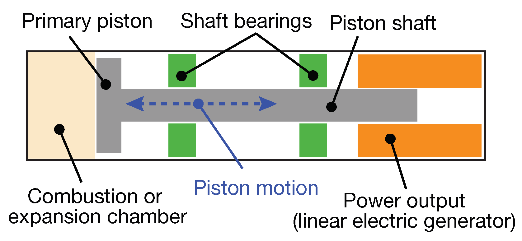
Figure 3.
Free piston engine–generator (FPEG) assembly (left) with forces acting on its piston shown (right) [40].
Figure 3.
Free piston engine–generator (FPEG) assembly (left) with forces acting on its piston shown (right) [40].

Figure 4.
Plot of free piston engine displacement (blue) and velocity versus conventional engine (red) for one piston cycle [47].
Figure 4.
Plot of free piston engine displacement (blue) and velocity versus conventional engine (red) for one piston cycle [47].
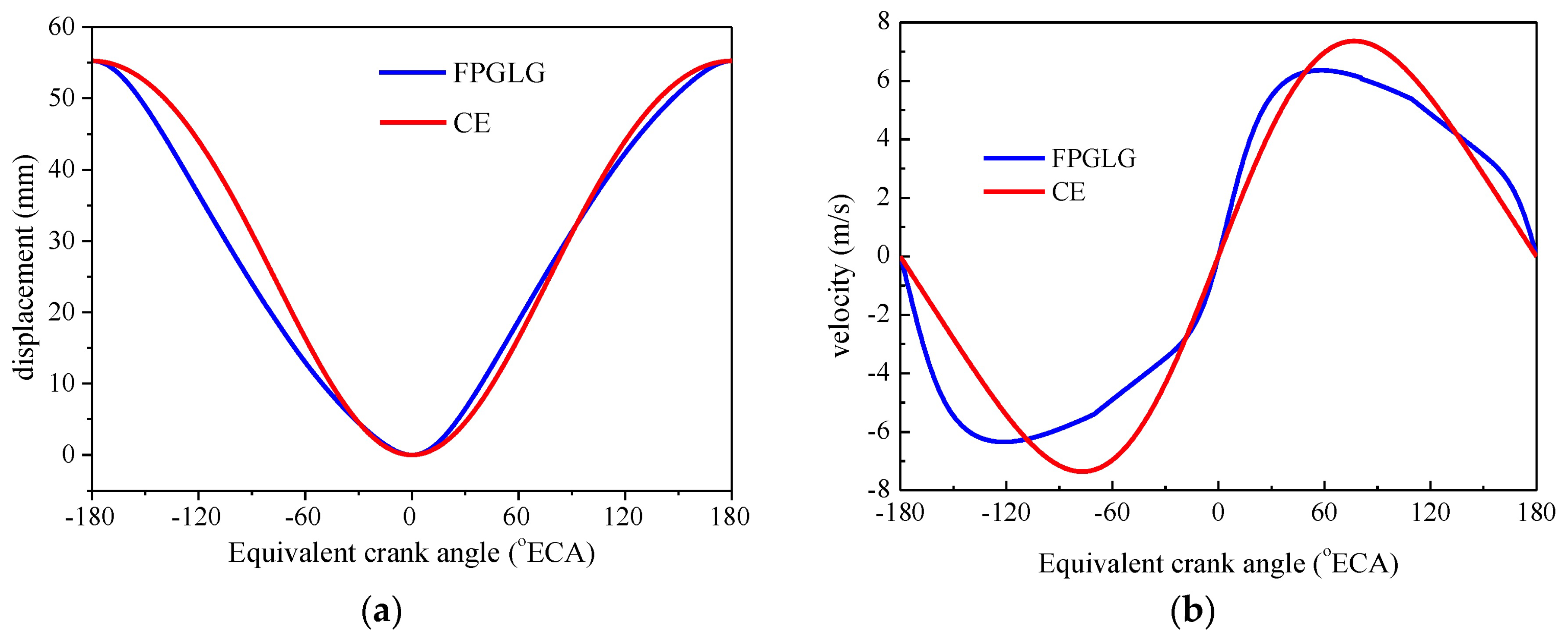
Figure 5.
Free piston engine–generator setup with: (1) cylinder; (2) generator; (3) air intake system; (4) fuel injection system; (5) scavenging case; and (6) ignition system [47].
Figure 5.
Free piston engine–generator setup with: (1) cylinder; (2) generator; (3) air intake system; (4) fuel injection system; (5) scavenging case; and (6) ignition system [47].
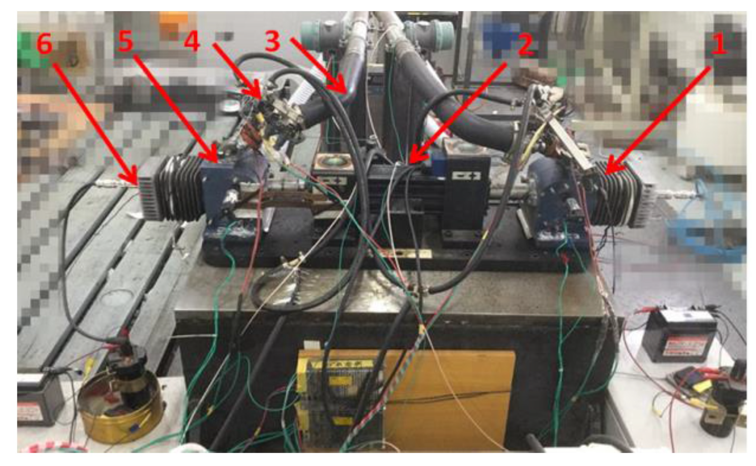
Figure 6.
An overview of millimeter scale FPE: (A) schematic sketch of the FPE with heat input and power output access ports shown; and (B) effect of different piston mass “m” on expander P-V curve with constant load and heat inputs [10].
Figure 6.
An overview of millimeter scale FPE: (A) schematic sketch of the FPE with heat input and power output access ports shown; and (B) effect of different piston mass “m” on expander P-V curve with constant load and heat inputs [10].

Figure 7.
Working fluids comparison cycle optimizations with different working fluids operating in sub-critical ORC systems [57].
Figure 7.
Working fluids comparison cycle optimizations with different working fluids operating in sub-critical ORC systems [57].

Figure 8.
Working fluid expansion and rotary vane expander operation in the rotary vane expander: (a) filling process; (b) end of filling process; (c) end of expansion process; and (d) working fluid rejection process [70].
Figure 8.
Working fluid expansion and rotary vane expander operation in the rotary vane expander: (a) filling process; (b) end of filling process; (c) end of expansion process; and (d) working fluid rejection process [70].

Figure 9.
An overview of the miniature resonant heat engine (adapted from [6,30,37]): (A) a schematic sketch the engine that is modeled as a spring–mass–damper system; (B) a photograph of the prototype engine in the motoring test bed; and (C) a representative P-V diagram of the engine for an equivalence ratio = 0.65. Note the engine outputs 72 J/cycle at a thermal efficiency of 41.2%.

Figure 10.
Thermal energy harvesting: P3 MEMS-based heat engine [82]. The inset shows the schematic sketch of the engine.
Figure 10.
Thermal energy harvesting: P3 MEMS-based heat engine [82]. The inset shows the schematic sketch of the engine.
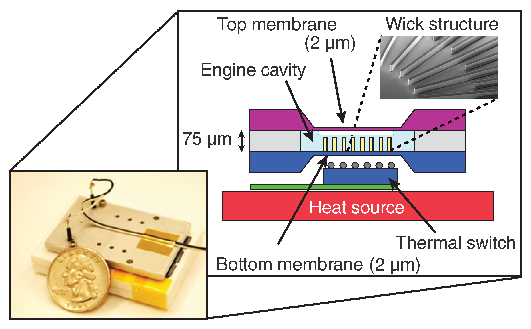
Figure 11.
Thermoacoustic engine pressure-volume operating cycle versus Stirling cycle [97].
Figure 11.
Thermoacoustic engine pressure-volume operating cycle versus Stirling cycle [97].

Figure 12.
The design of a solar thermoacoustic engine [98].
Figure 12.
The design of a solar thermoacoustic engine [98].

Table 1.
Summary of different power generation technologies over a wide range of sizes (0.006–500 cc). Note the technology classification: combustion-based (C) and External heat (E).
Table 1.
Summary of different power generation technologies over a wide range of sizes (0.006–500 cc). Note the technology classification: combustion-based (C) and External heat (E).
| Technology | Class | Device Specifications (Size, Fuel/Working Fluid, Thermal Efficiency ) | Challenge(s) | Application |
|---|---|---|---|---|
| MEMS IC engine [5] | C | 0.015 cc Premixed H2 + O2 – | Leakage loss | Micro propulsion |
| Two-stroke piston engine [115] | C | 0.5–1 cc Glow fuel 3–12% | Incomplete combustion | Micro-unmanned aerial vehicle (UAV) |
| MICSE [116] | C | 4 cc Butane vapor 22% | Leakage, friction, and heat losses | Portable power |
| Mesoscale compliant engine [37] | C | 21 cc Gasoline 45% (theoretical) | Super compliant structures | Micro propulsion |
| MEMS P3 heat engine [9,82] | E | 0.0006 cc 3MTM PF-5060DL 0.1% | Heat loss | Portable power |
| Miniature free piston expander [13] | E | 0.03 cc HFE 7200 – | Piston sealing and friction loss | Low temperature waste heat scavenging |
| Thermo- fluidic [110,111] | E | 0.06 cc Organic Fluids 15% theoretical, 0.2% experiment | Heat Exchanger Efficiency, Internal Flow Efficiency | Waste heat recovery & Combined Heat Power |
| Small vane expander [74] | E | 2.0 cc R123 17.2% | Tip sealing, leakage loss | Waste heat recovery |
| Small scroll expander [68] | E | 54.8 cc R123 7.2% | Leakage loss | Waste heat recovery for auxiliary power |
| FPE-LG [12] | E | 502 cc Organic fluids 66% | Working fluid flow control | Waste heat recovery from vehicles |
| Small ORC scroll expander [60] | E | 180.7 cc Organic Fluids 7–8% overall | Leakage loss Cost | Off-grid power generation |
| Thermo- acoustic [117] | E | 90 mm diameter Air 14.5% thermal to electric | Regenerator Efficiency | Waste heat recovery/solar |
© 2018 by the authors. Licensee MDPI, Basel, Switzerland. This article is an open access article distributed under the terms and conditions of the Creative Commons Attribution (CC BY) license (http://creativecommons.org/licenses/by/4.0/).
Share and Cite
MDPI and ACS Style
Burugupally, S.P.; Weiss, L. Power Generation via Small Length Scale Thermo-Mechanical Systems: Current Status and Challenges, a Review. Energies 2018, 11, 2253. https://doi.org/10.3390/en11092253
AMA Style
Burugupally SP, Weiss L. Power Generation via Small Length Scale Thermo-Mechanical Systems: Current Status and Challenges, a Review. Energies. 2018; 11(9):2253. https://doi.org/10.3390/en11092253
Chicago/Turabian StyleBurugupally, Sindhu Preetham, and Leland Weiss. 2018. "Power Generation via Small Length Scale Thermo-Mechanical Systems: Current Status and Challenges, a Review" Energies 11, no. 9: 2253. https://doi.org/10.3390/en11092253
Note that from the first issue of 2016, this journal uses article numbers instead of page numbers. See further details here.