1. Introduction
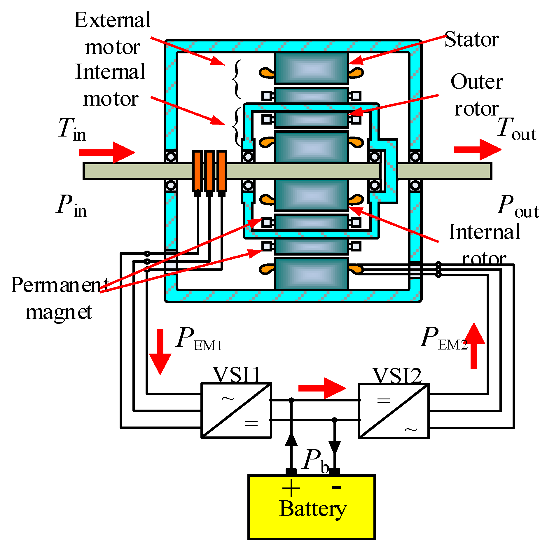
The compound structure permanent-magnet motor (CSPM) is a new electric transmission device. Its basic structure is shown in
Figure 1. It consists of an inner rotor, an outer rotor and a stator. The outer rotor is composed of two layers of inner and outer layers. Ignoring the influence of magnetic field coupling, the motor can be regarded as a combination of two independent motors inside and outside. The internal motor EM1 is composed of an inner permanent magnet and an inner rotor, and the external motor EM2 is composed of an outer permanent magnet and a stator. The CSPM has two mechanical ports and two electrical ports, which realize efficient energy transmission, so the CSPM has broad application prospects in wind power generation, ship propulsion systems and hybrid electric vehicles [
1].
A correlative research study demonstrates that a suitable Energy Management Strategy (EMS) can reduce HEV fuel consumption [
2,
3,
4,
5,
6,
7,
8,
9,
10,
11,
12,
13,
14,
15,
16,
17,
18,
19], and it is also beneficial to emissions reduction. In [
2], dynamic programming was investigated for reducing the fuel consumption of vehicles when the future driving conditions are acquired. However, due to the computational complexity, the results obtained from dynamic programming cannot be executed directly. To solve this question, approximated dynamic programming [
3] is proposed as an alternative solution. Since analytical optimization methods employ a mathematical equation to achieve the solution, their computation speed is faster than that of simple numerical methods. In this category, as an optimal control method, EMS based on Pontryagin’s minimum principle (PMP) is proposed [
4]. Unfortunately, this approach only works under the condition that the future driving conditions are known in advance. That is to say, vehicles must be able to communicate with road traffic systems [
5]. In practice, currently this is difficult to achieve on a large scale.
For online implementation, in [
6,
7], the authors have developed a generic framework of online EMS for HEVs, where an evolutionary algorithm is used for online optimization of the power-split and battery SOC management. Due to the merit that the rule-based energy management algorithms are easy to implement in real time, this control strategy have been broadly applied in practical HEV EMS. In [
8,
9,
10], rule-based EMS are used to split the power demand between the internal combustion engine (ICE) and the battery. In [
11,
12] the authors adopted a rule-based EMS and they introduced a proper supervisory environment for a complex structure control. However, to create these rules, extensive engineering experience and extensive experimental data are needed. Moreover, this cannot improve the fuel economy significantly. To overcome this problem, [
13,
14] propose a rule-based strategy combine with a fuzzy inference system. As a fuzzy system, due to its simple logic, it can be implemented in real time applications. In addition, it easy to model nonlinearity and uncertainty. However, the drawback of fuzzy systems is that they cannot achieve large modifications of the system modelling. This matter can be settled by the use of genetic algorithms (GAs) [
15], which optimize the membership functions of the fuzzy controller for several matters while using appropriate fitness function. The trouble with GAs is random convergence of the solutions. Moreover, the operational speed of the optimization algorithm impedes the widespread application of GAs. To overcome this problem, the Artificial Neural Network (ANN) concept was introduced in [
16,
17,
18]. ANNs are especially good at self-learning, adaptive ability and parallel distributed processing. Therefore, ANNs can be used to save the time consumed for optimization. They are suitable for improvement of instantaneous optimization strategies [
19].
There are a variety of power source output couplings in HEVs with new topologies. The energy management strategy in traditional HEVs cannot achieve efficient power output distribution. Therefore, an optimized energy management strategy is proposed to improve the power, energy transmission efficiency and fuel economy of the new HEV. Through the optimized energy management strategy of this paper, the power, comfort, energy saving and environmental protection of HEVs are satisfied under different working conditions. The research of this paper promotes the development of electromagnetic continuously variable transmission. This paper develops a new theoretical foundation for the practical application of CSPM in HEVs.
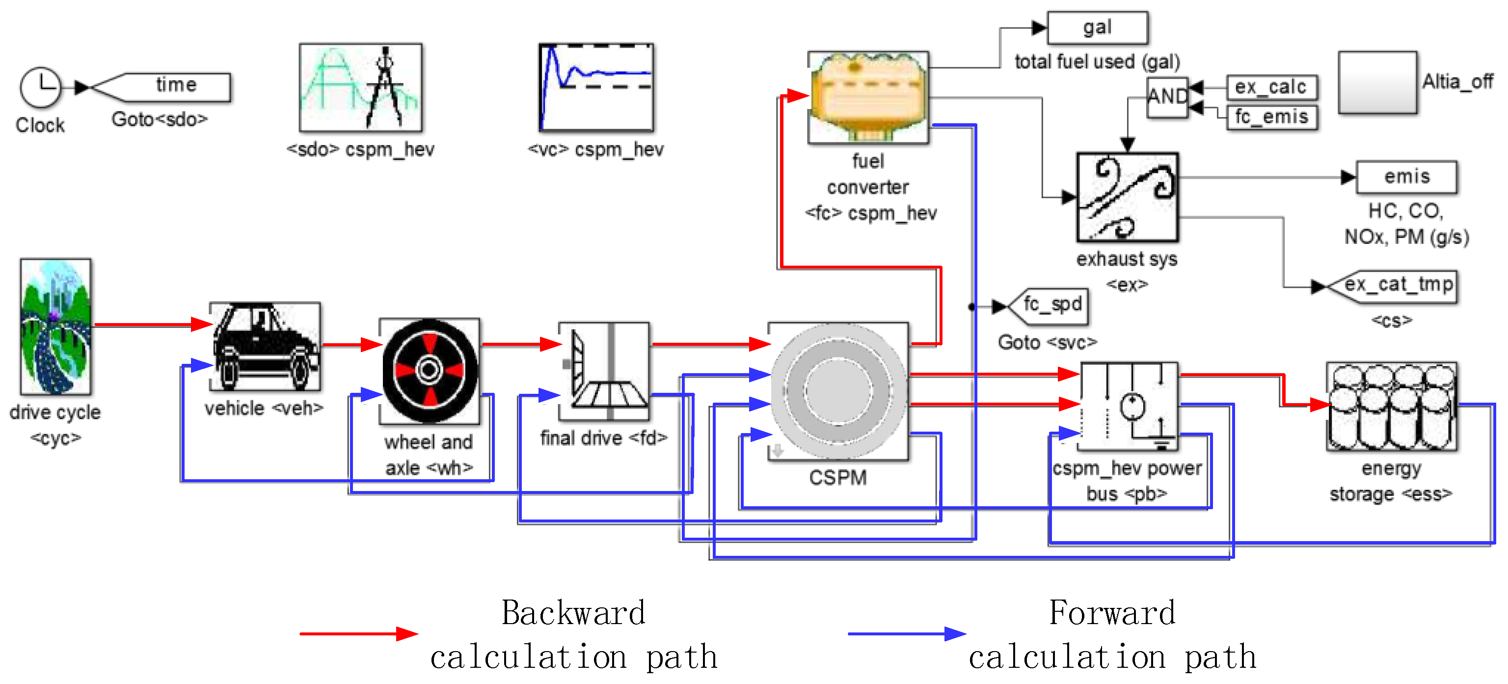
Section 2 of this paper analyzes the operation mode of CSPM-HEV. Moreover, in order to facilitate the simulation analysis, the simulation model of CSPM-HEV was established and the simulation parameters of each component were determined in
Section 3. In
Section 4, based on the CSPM-HEV energy transfer characteristics, an instantaneous optimization energy management strategy based on a BP neural network was proposed, and the corresponding controller was designed in
Section 5.
2. CSPM-HEV Operating Mode Analysis
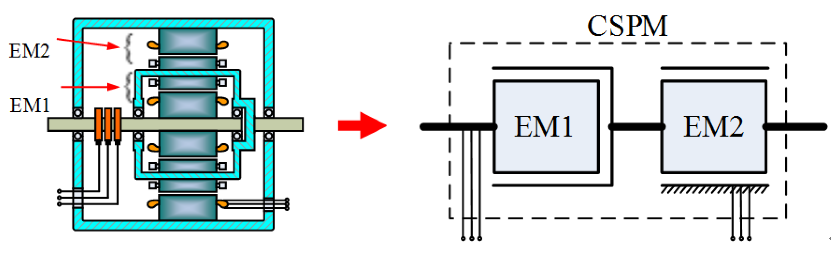
After the structure optimization of CSPM, the magnetic field coupling, between internal and external motors in a CSPM can be neglected, so the CSPM can be seen as two independent permanent-magnet motors.
Figure 2 is its equivalent schematic diagram. For simplification of the analysis, it was based on the equivalent permanent-magnet motor structure shown in
Figure 2.
According to the function of the CSPM in the HEV, the operating modes can be mainly divided into hybrid mode, starter mode, regenerative braking mode, generator mode and motor mode.
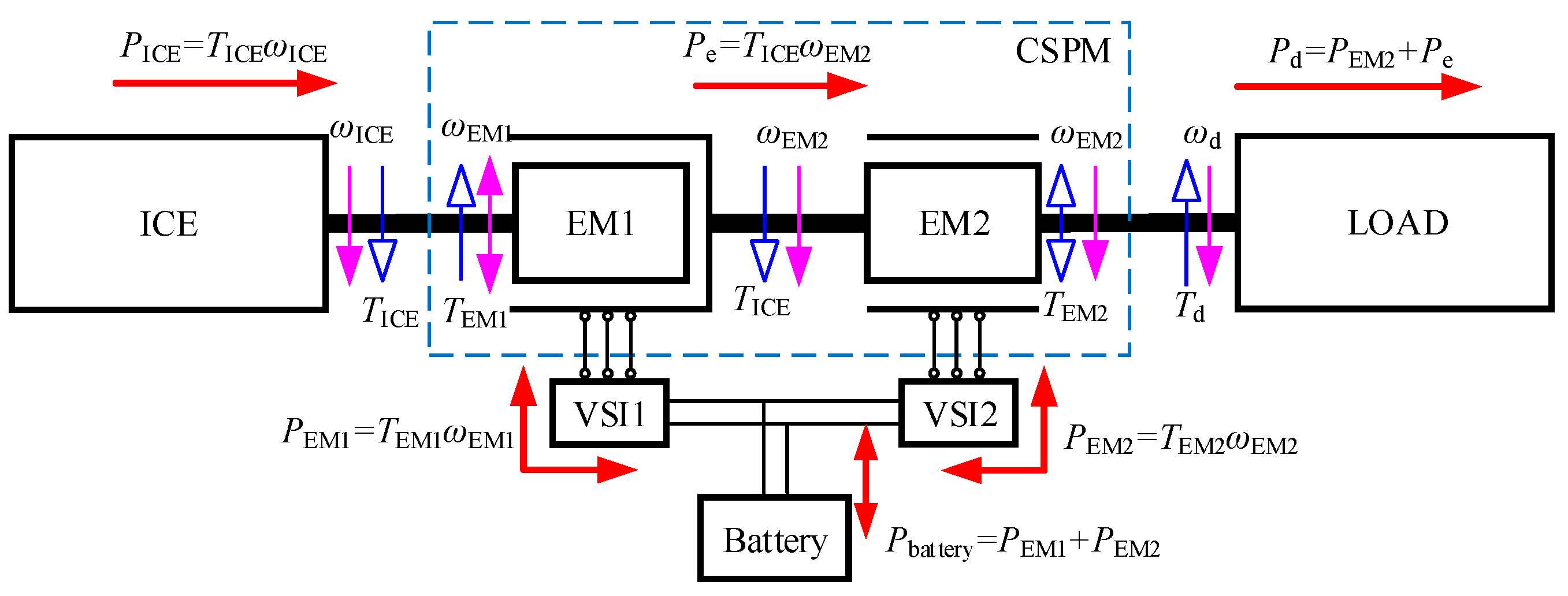
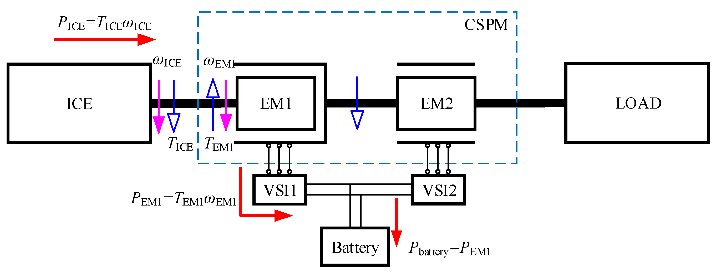
(1) Hybrid mode
When the vehicle demand torque is large or the battery SOC is low, the engine and the battery will jointly provide energy for vehicle. The CSPM works in the hybrid mode at this time, and its power flow is shown in
Figure 3.
(2) Starter mode
In a conventional vehicle, the engine needs an external force to start. This process is completed by an electric motor. However, the CSPM-HEV avoids this process, and the inner motor EM1 can realize this function. Its power flow is shown in
Figure 4.
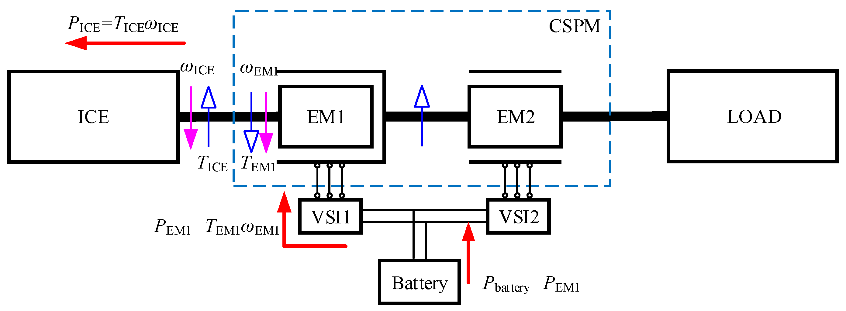
(3) Generator mode
If a vehicle is static for a short time and the battery SOC is low, the external motor of the CSPM stops working, and the engine drives the inner motor to operate as generator. Therefore, the battery is charged. Its power flow is shown in
Figure 5.
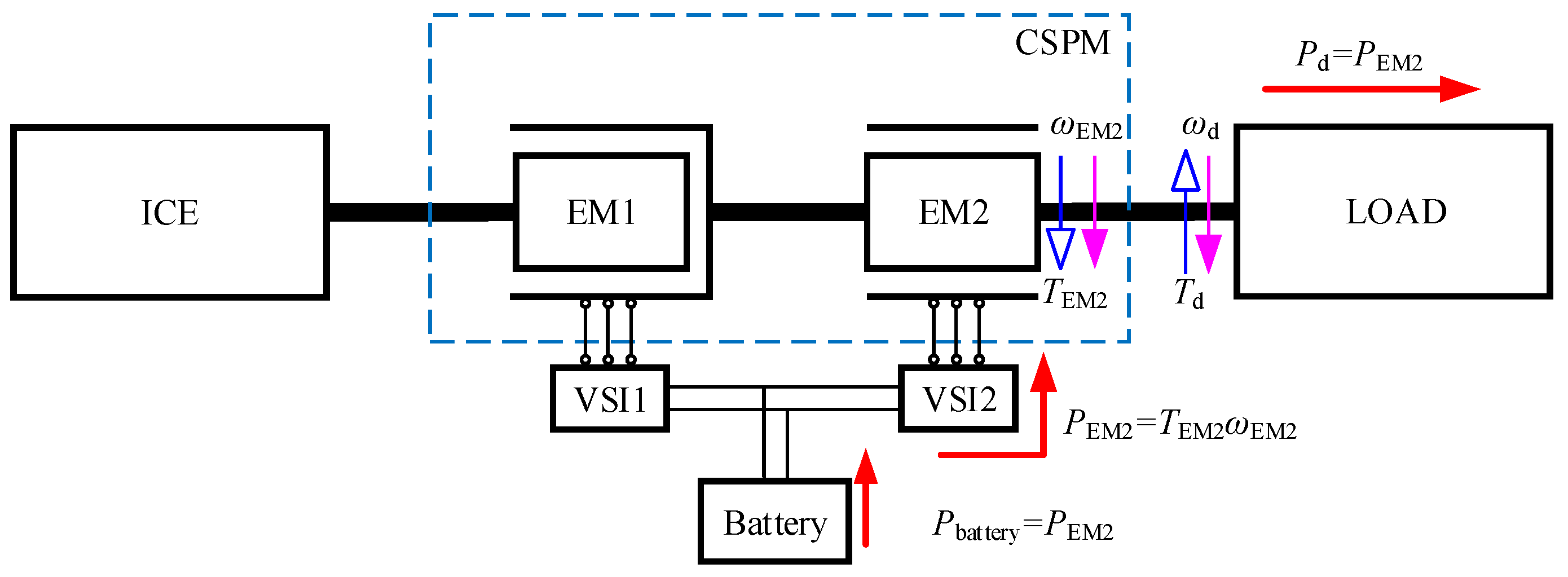
(4) Motor mode
When the vehicle runs at low speed and the battery SOC is high, the CSPM-HEV works in the pure electric mode. At this time, the inner motor EM1 and the engine do not work, and the outer motor EM2 works as a motor to directly drive the vehicle, and the system energy is all provided by the battery. Its power flow is shown in
Figure 6.
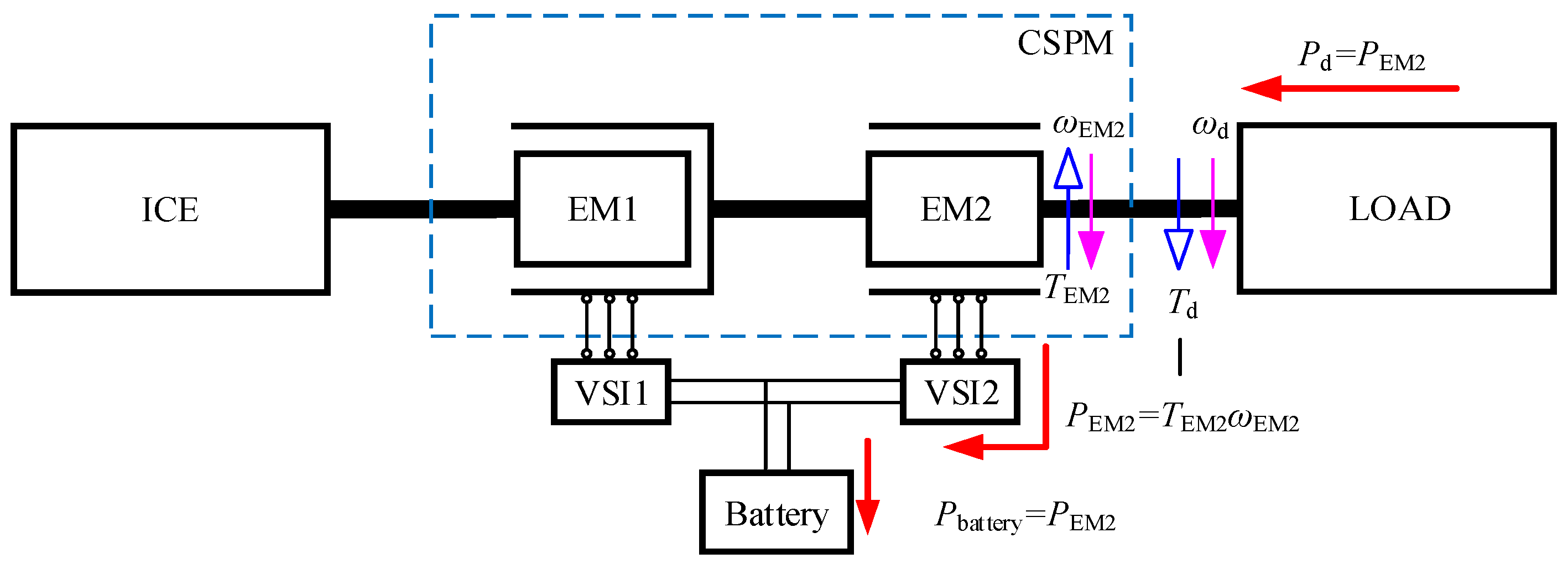
(5) Regenerative braking mode
When the vehicle brakes, the EM2 works in the power generation state, and the recovered energy is stored in the battery. The power flow is shown in
Figure 7.
4. Instantaneous Energy Management Strategy Based on BP Neural Network
To some extent, the instantaneous optimization energy management strategy (IO-EMS) compensates for the shortcomings of energy management strategies based on rules and global optimization. Due to the independence from expert experience, the optimized control can be achieved at each moment. Compared with global optimization, IO-EMS can adapt to different working conditions. However, due to the massive calculations required, IO-EMS cannot guarantee the real-time performance, which hinders its application.
Artificial Neural Networks (ANNs) are a computing system formed by connecting a number of simple processing units (neurons). It is also called “neural network”, which mimics the operating mechanism of the human brain and enables the machine to have some features of the human brain. The control system utilized the continuous learning, profound memory and adaptability of the neural network, so that the control system can realize the non-linear mapping between input and output. Neural networks are suitable for modeling and the control of systems with many uncertainties [
22].
This section develops an IO-EMS based on the principle of “minimum power loss”, and it proposes a real-time energy management strategy based on a BP neural network (BP-EMS). BP-EMS improves the poor real-time performance of IO-EMS. The optimal solution at each moment in each operating condition was collected as a training sample of the neural network. Then, the BP neural network was trained. Afterwards, the BP neural network controller was built.
The optimization based on the “minimum power loss” principle is to find a set of values, which minimizes power loss among all the power flow combinations, and these values are used to calculate the torque and speed of engine demand. Thus, the minimum power loss of the system is achieved, and the optimal vehicle efficiency is achieved eventually.
The speed difference between the two shafts is continuously variable, which is similar to the traditional continuously variable transmission, so that the transmission ratio
iCSPM can be defined according to the concept in the mechanical transmission:
where
is output speed of the engine after the gear.
When the CSPM-HEV runs in hybrid mode, the power between the EM1 and the engine has the following relationship:
From Equation (2), we can get that if , EM1 works in the power generation state; if , EM1 works in the electric state.
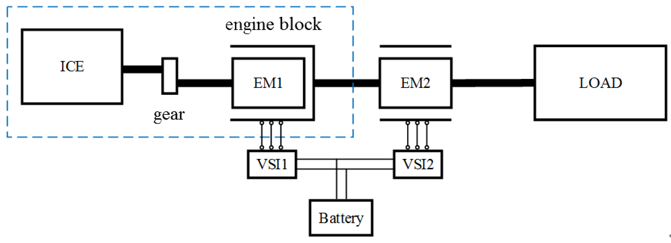
When the CSPM-HEV runs, the required power of the drive axle is definite. For simplification of power flow analysis, the engine and the EM1 can be regarded as a whole, and they are defined as the engine block, as shown in
Figure 9.
Since the external motor EM2 is independent with the engine, the power distribution coefficient
can be defined. At this time, the output power of the engine group and the EM2 are:
In the equation, is the required power of the axle.
Combining Equation (2) with Equation (3), the power of the engine and internal motor EM1 can be expressed as:
Due to the inevitable power loss during the powertrain transmission and the mechanical transmission, the power loss of the drive axle is mainly concentrated in four parts: engine, internal motor EM1 and its controller, external motor EM2 and its controller, battery, respectively. The total system power loss
can be expressed as:
In the above equations,
is the engine efficiency;
is the EM1 and its controller efficiency;
is the EM2 and its controller efficiency; and
is the battery efficiency. They have the following relationship:
Substituting the output power of engine and EM1/EM2 into Equation (7):
In the CSPM-HEV, the energy in the battery comes from two parts: one is the energy recovered by regenerative braking, and the other is converted from the mechanical energy of the engine. The latter accounts for a large proportion. Since the battery will wear out during charging and discharging, when analyzing the system loss, the loss of the battery should be considered. Therefore, the battery loss compensation factor is introduced, which can be expressed as:
In the equation, , , represent the average efficiency of the engine, CSPM, and battery, respectively.
When the battery is discharged, the system power loss can be expressed as:
When the battery is charging, the system power loss
is equal to
:
From Equation (10), it can be seen that the efficiency of each system component can be obtained by looking it up in the table, according to the corresponding iCSPM and . Consequently, the power loss of the vehicle will be only related to these two variables. Therefore, when the power distribution coefficient is a definite value, and Equation (10) is a linear equation with one unknown. It can be known from MATLAB calculation that the power loss becomes small firstly and then becomes large as the gear ratio iCSPM increases. In this process, there is a minimum value of the power loss. If within the value range of the power distribution coefficient , all minimum values form a set, then, the minimum value in this set is the minimum power loss under the specific operating condition. Similarly, if the transmission ratio is determined first, then the relationship between the power distribution coefficient and the power loss is same as the above conclusion.
At each moment under the IO-EMS, there are multiple combinations of (
iCSPM,
), and the power loss of each combination will be compared with each other, to find the combination that minimize the power loss:
According to the (
iCSPM,
) combination at each moment, the required power, speed and torque of the engine, EM1 and EM2 can be calculated under the current combination:
In the equation, is the transmission ratio of the gear, is the required speed of the axle.
In the process of solving the IO-EMS algorithm, the power, speed, and torque of the engine, EM1, and EM2 must satisfy the following constraints:
The implementation of the IO-EMS based on the minimum power loss is as follows: At every moment when the CSPM-HEV operates in the hybrid mode, all possible combinations (, ) are listed firstly, then, these combinations are adopted to calculate the power, torque, and speed required for the engine, EM1, and EM2 by Equations (15)–(17). The calculation results must satisfy the constraints shown in Equation (18). Those combinations that do not meet the constraints will be discarded. Afterwards, according to the required power, torque and speed of the engine, EM1 and EM2, the efficiency of the component is obtained by looking up the table. After this, the power loss, which satisfy the condition, is calculated by Equations (12) and (13). When the loss is minimum, the corresponding (iCSPM, ) combination is obtained. Next, according to Equations (15)–(17), the power, speed, and torque of the engine, EM1, and EM2 corresponding to the combination are calculated. Eventually, these data are used to control the system operation, and the minimum vehicle power loss is realized.
5. Neural Network Controller Design
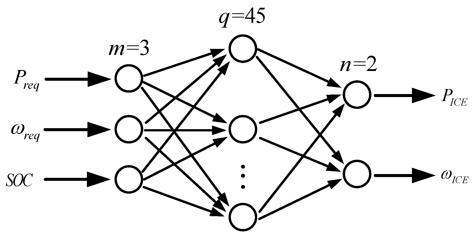
In order to realize the Back-Propagation Neural Network Energy Management Strategy (BP-EMS), this paper designed a neural network controller, structure of which is shown in the
Figure 10. According to the three input variables in the IO-EMS, three neurons were designed on the input layer, they are axle power demand, axle speed demand and battery SOC, respectively. Afterwards, two neurons were designed on the output layer, these two neurons represented the engine power and speed respectively. By the engine speed and torque, the operating point of the internal and external motors can be calculated, so that realizing the efficient energy management of the system.
For the three-layer BP neural network, the number of input and output layer neurons is determined, so the hidden layer neurons determine the network structure and have an important impact on network performance. If the number of neurons in the hidden layer is too small, the network is difficult to train and its performance will be poor; if there are too many hidden layer neurons, the training time of the network will be increased greatly, and the training will easily fall into a local minimum without the optimal advantage. Moreover, the excessive neurons will also bring difficulties for hardware and software implementations. According to the principle of simplifying the network structure as much as possible, this paper determined the number of hidden layer neurons by continuous experimentation.
5.1. BP Neural Network Training
There is an important relationship between the selection of training samples and their performance in neural networks, so the following aspects should be noted when learning the sample selection of neural network controllers:
- (1)
The sample should be widely representative and reflect the working characteristics of all possible operating conditions of the HEV.
- (2)
The neural network after the sample learning has good generalization ability.
- (3)
Do not have too many samples, otherwise it may lead to over-fit of the network.
In the BP neural network controller of this paper, the input and output variables such as vehicle power, speed, and battery SOC vary greatly in magnitude, and they need to be normalized before training, that is, all the data were converted into (0, 1), to eliminate the impact of different orders of magnitude on the network. The linear function method was used here, as shown in the following equation:
In the equation, represents the sample; and represent the sample maximum and minimum values respectively; is the standardized sample.
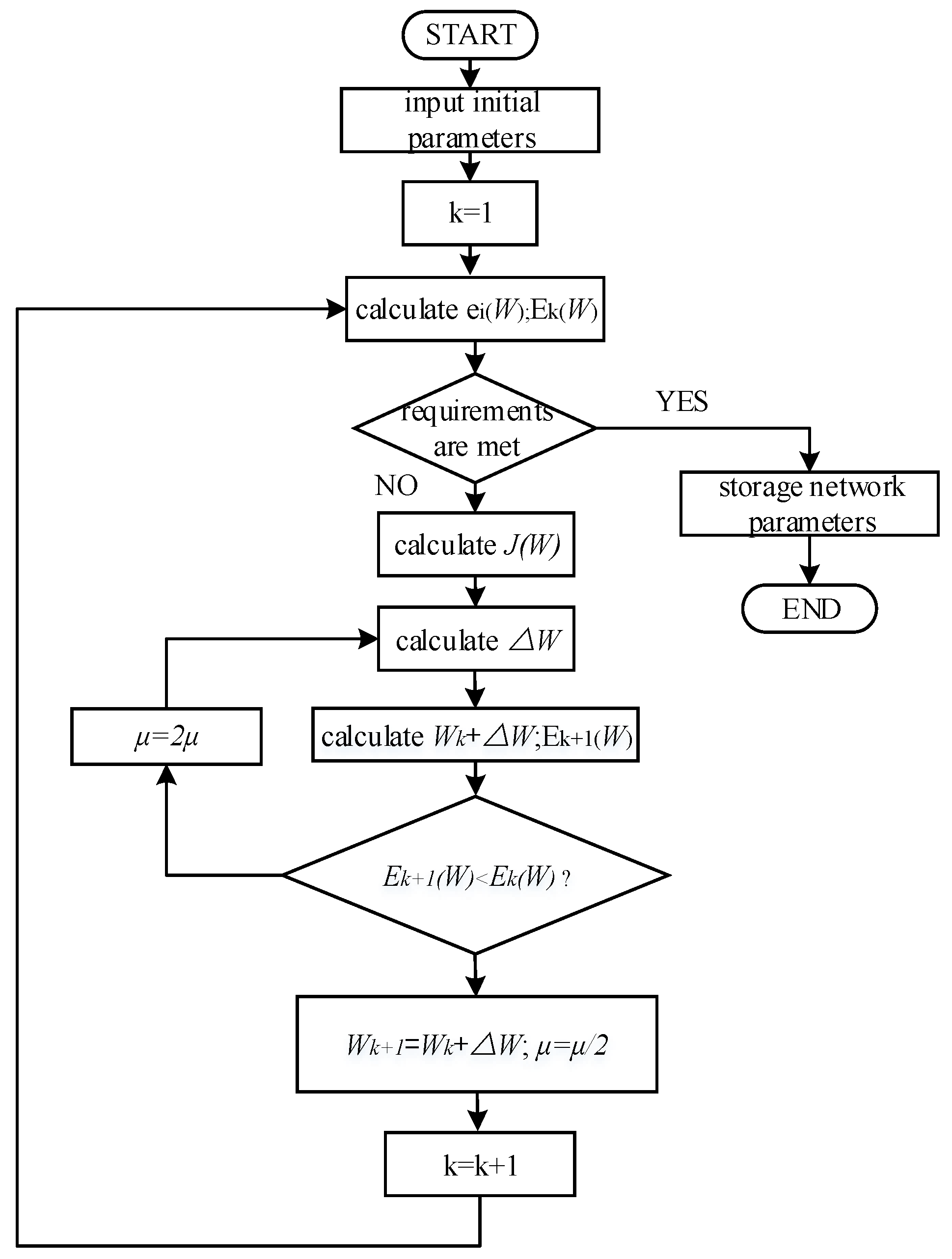
In order to overcome the drawbacks of the standard BP algorithm, such as the difficulty in adjusting initial network weight, learning rate and momentum coefficient, and the long training time and slow convergence rate, the neural network controller adopted Levenberg-Marquardt algorithm for sample learning. The flow chart is shown in the
Figure 11, and the training steps are as follows:
Step 1: The required power, speed, and battery SOC are putted in the training sample to the network and the error between the output and the target value
(
,
as the total number of training samples) is calculated. Here, the error indicator was defined:
In the equation, is the vector group formed by the weights and thresholds in the network, is the number of iterations of network learning.
Step 2: If the requirements are satisfied. If yes, training will be saved and ended. If not, go to the next step.
Step 3: The Jacobian matrix is calculated:
Step 4: The adjustment rate is solved through the following equation:
In the equation,
is a non-negative number that indicates the speed of network learning.
Step 5: is calculated by Equation (20). If , then , , skip to Step 1; otherwise, go to Step 4.
5.2. Analysis of Simulation Results
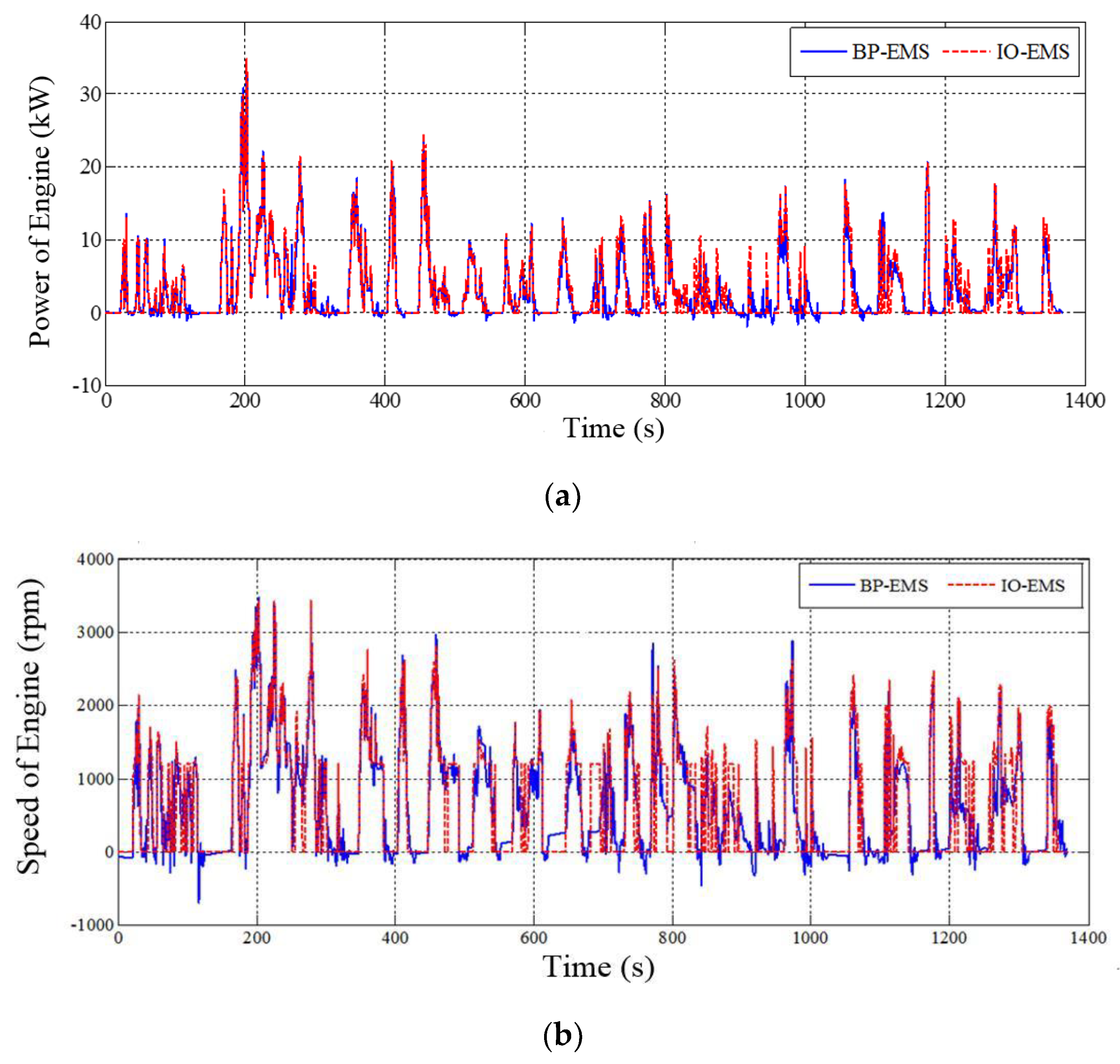
In order to verify the control effect of the BP-EMS, the Urban Dynamometer Driving Schedule (UDDS), US06 Highway Cycle (US06 HWY), and New European Driving Cycle (NEDC) were simulated and the results were compared with the corresponding results of IO-EMS.
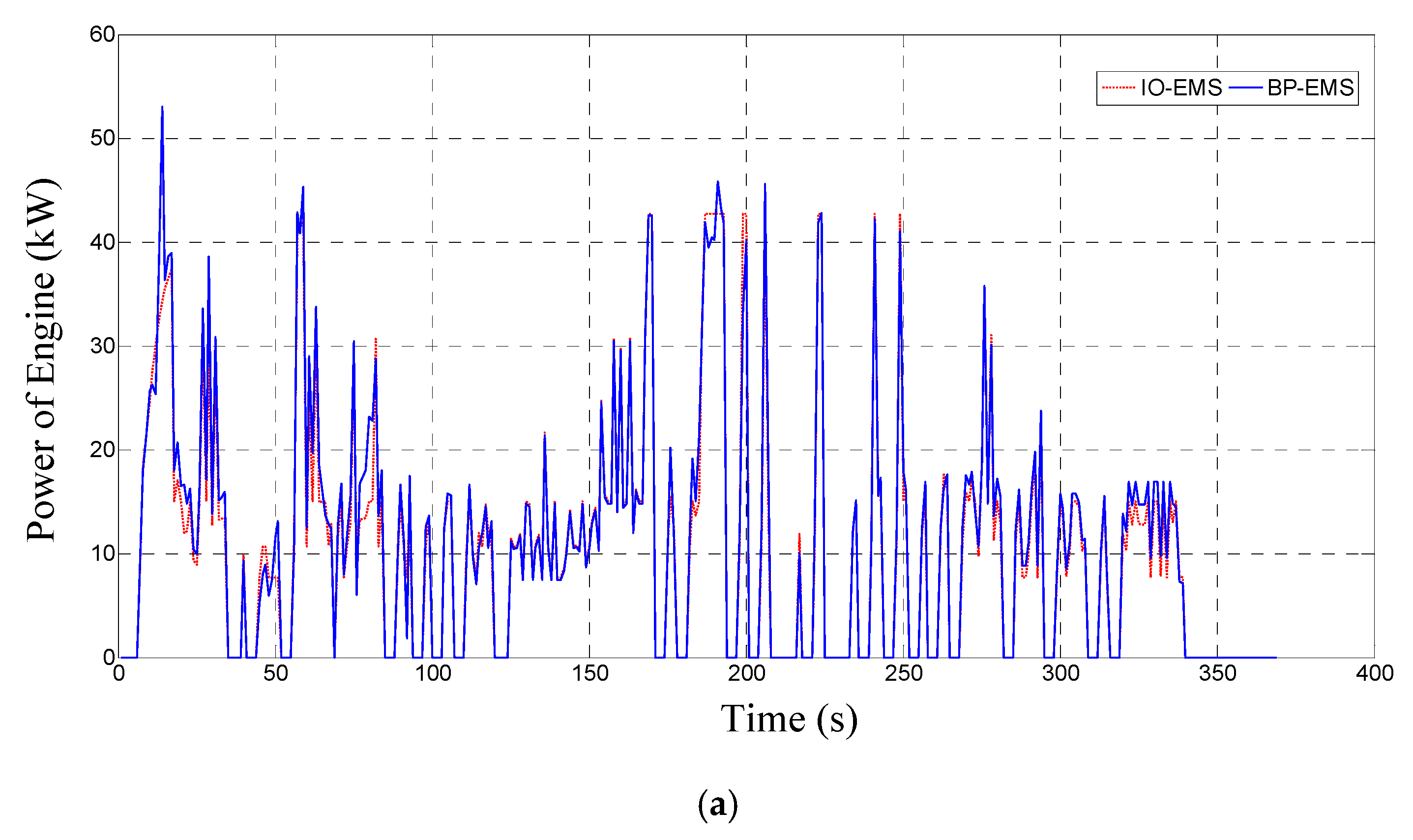
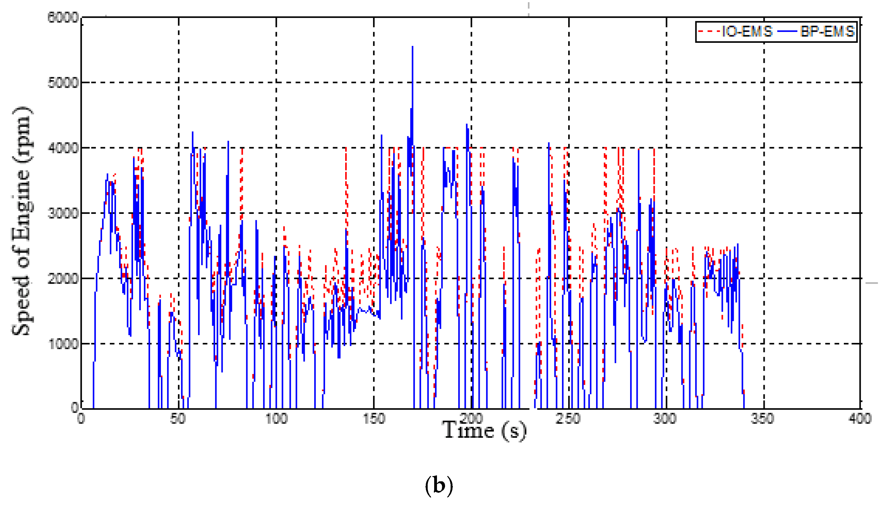
Figure 12 shows the engine output power and torque command value based on the two control strategies under UDDS conditions. It can be seen from this figure, if engine power and torque are negative values, the invalid command values of the engine in the closed state are removed, the BP neural network controller will give a good effect on the sample learning. It realizes the nonlinear mapping between vehicle demand power and speed, battery SOC and engine power and torque command value.
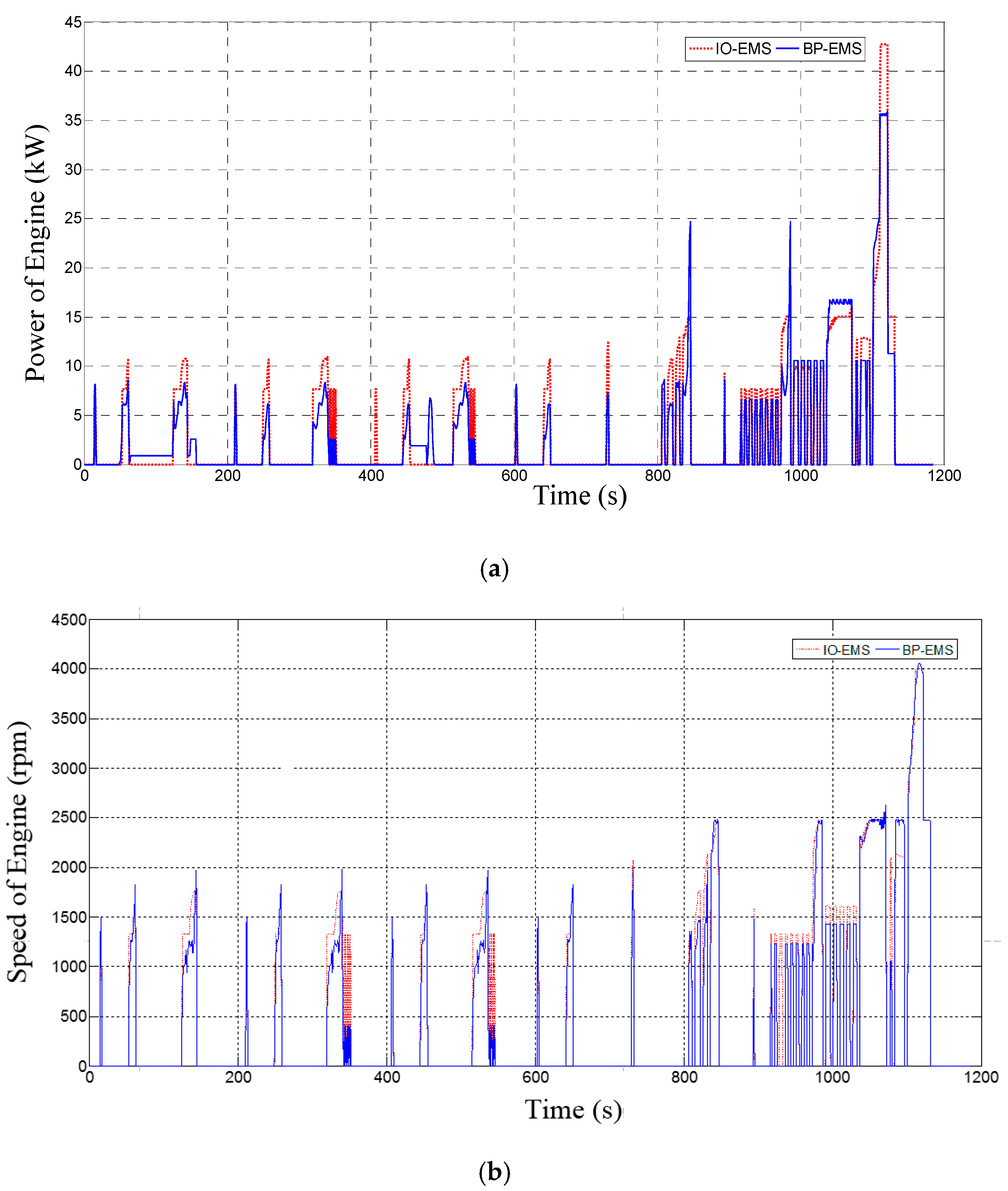
From simulation results of US06 HWY and NEDC driving cycle, it can get the same analysis results as UDDS driving cycle. Simulation results of US06 HWY and NEDC are shown in
Figure 13 and
Figure 14 respectively.
In order to make the simulation results more convincing, this paper uses Mean Square Error (MSE) to process the data obtained from the two control strategies in different working conditions. The results are shown in the
Table 3. For the simplification of calculation, the unit of speed is a thousand revolutions per minute. The calculation results show that the control effect of the two control strategies is similar, and the introduction of neural network does not decrease the control performance of instantaneous optimization.
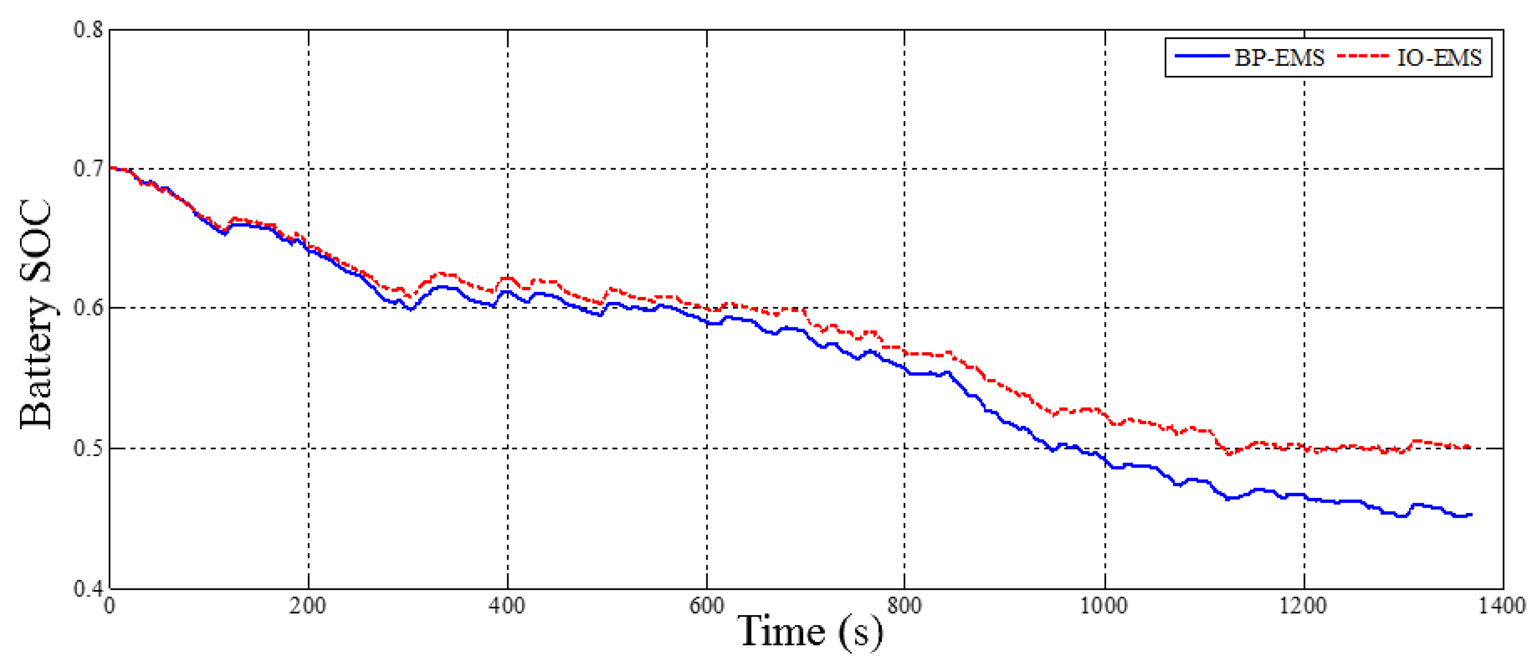
Figure 15 shows the battery SOC variation based on two control strategies under UDDS conditions. It can be seen that the battery SOC is stable at the end, and the changes are similar, indicating the effectiveness of the real-time EMS based on a BP neural network.
It can be seen from
Table 4 that the BP-EMS can simulate the control rules of the IO-EMS well, and the control effect is similar to that of the IO-EMS. The average fuel consumption difference between these two strategies under various operating conditions is 1.2%, while the average operation speed of the BP-EMS is improved effectively (the improvement degree is 98.1%), which shows that the improved control strategy has a high application value.


