Article

Synthesis of the ZnO@ZnS Nanorod for Lithium-Ion Batteries

1
School of Materials Science and Engineering, Hebei University of Technology, Tianjin 300130, China
2
Synergy Innovation Institute of Guangdong University of Technology, Heyuan 517000, China
*
Author to whom correspondence should be addressed.
Energies 2018, 11(8), 2117; https://doi.org/10.3390/en11082117
Submission received: 2 July 2018 / Revised: 12 August 2018 / Accepted: 13 August 2018 / Published: 14 August 2018

Abstract

:
The ZnO@ZnS nanorod is synthesized by solvothermal method as an anode material for lithium ion batteries. ZnS is deposited on ZnO and assembles in nanorod geometry successfully. The nanosized rod structure supports ion diffusion by substantially reducing the ion channel. The close-linking of ZnS and ZnO improves the synergetic effect. ZnS is in the middle of the ZnO core and the external environment, which would greatly relieve the volume change of the ZnO core during the Li+ intercalation/de-intercalation processes; therefore, the ZnO@ZnS nanorod is helpful in maintaining excellent cycle stability. The ZnO@ZnS nanorod shows a high discharge capacity of 513.4 mAh g−1 at a current density of 200 mA g−1 after 100 cycles, while a reversible capacity of 385.6 mAh g−1 is achieved at 1000 mA g−1.

1. Introduction

Lithium-ion batteries (LIBs) have developed very rapidly since the 1990s and have been widely adopted by portable electronics, electric vehicles and other electronic devices. Lithium-ion battery technology has the potential to be one of the major power sources in the future. Graphite is widely used as a commercial anode material and is widely adopted in different LIB technologies. However, the theoretical specific capacity of graphite is 372 mAh g−1, which cannot meet the practical requirements in high-energy density applications. Therefore, it is of great importance to synthesize new anode active materials to improve the electrochemical performance of LIBs [1,2,3,4,5,6].
There are several materials that have been researched and synthesized as potential anode materials for LIBs. Metal oxides, such as Fe2O3 [7], GeO2 [8], MnO [9], SnO [10], and ZnO [11], have appealed to many researchers working in LIB technology due to their high theoretical capacity values, comparatively safe handling and cost-effectiveness [12]. Among these materials, zinc oxide (ZnO) has shown the potential to be a prospective anode material. Utilizing ZnO has several advantages, such as simple synthesis methods, abundant reserves on the Earth, and the fact that it is environmentally friendly [13]. Most importantly, the theoretical specific capacity of ZnO is 978 mAh g−1, which leads this to be a good potential material for LIBs [14].
However, there are two inevitable drawbacks when utilizing pure ZnO as the electrode material. Firstly, a study indicated that ZnO was reduced into metallic Zn and a LixZn alloy during the lithium insertion procedure, and in the lithium extraction procedure, the LixZn alloy disappeared and ZnO reappeared [15], so there was a significant change in volume during the Li+ intercalation/de-intercalation processes, which can lead to loss of electrode active materials. Volume expansion can also increase high stress in active materials and deteriorate the structure of the materials and the battery itself [16]. In addition, the low conductivity of ZnO limits its use in electrode materials [17].
There are two different strategies that have been adopted to solve these LIB problems. One of them focuses on decreasing the size of particles, which would counteract the change in volume during the insertion and extraction of ions and shorten the lithium-ion transmission path [18]. The second method depends on different ZnO nanostructures blending with various materials. In particular, coating ZnO with suitable materials can greatly ease the volume expansion during charge and discharge [19]. For example, Qin Li and coworkers reported that ZnO/ZnO@C composites were prepared by a simple carbonization process of ZnO/ZnO@ZIFs-8 (zeolitic imidazolate frameworks), and an initial capacity of 359 mAh g−1 was tested at 5.0 A g−1 with a capacity retention of 85.3% after 500 cycles [20]. Recently, the ZnO@ZnS composite has been used in many aspects. For example, Li and coworkers reported that ZnO@ZnS composite material was synthesized with a convenient chemical synthesis by sulfidation of ZnO nanospindles [21]. Yu et al. synthesized ZnO@ZnS hollow dumbbells-graphene composites and obtained highly efficient photocatalysts activity [22]. Inspired by these excellent activities of ZnO-ZnS composite materials, we have modified ZnO to obtain a ZnO@ZnS nanorod and used it as an anode material for LIBs. Meanwhile, ZnS has many advantages, such as its non-toxic character, highly natural abundance, and low cost. Its high theoretical specific capacity (962.3 mAh g−1) also makes it one of the ideal candidates for anode material.
Herein, we synthesize the ZnO@ZnS nanorod through a simple solvothermal method. This simple low-cost synthesis route is highly reproducible and has low costs because it has simple chemical synthesis steps. When constructed in LIBs as an anode material, the produced ZnO@ZnS nanorod demonstrates high specific capacity, great cycle stability and distinguished rate performance. These features make ZnO@ZnS a remarkable fitting as anode material in LIBs.

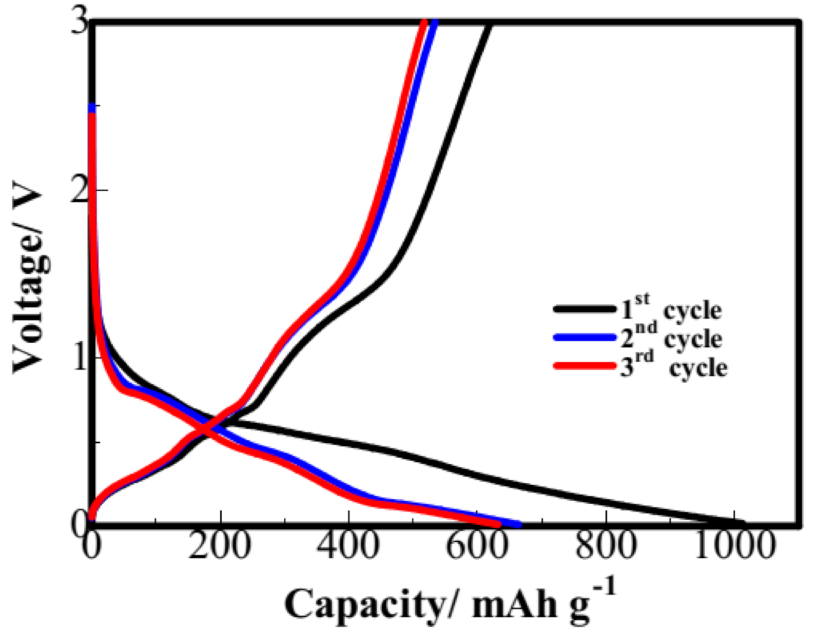
2. Results and Discussion

XRD patterns of the ZnO@ZnS nanorods are presented in Figure 1. It contains obvious peaks of ZnO and ZnS, the peaks at 31.8°, 34.5°, 36.2°, 47.5°, 56.5°, 62.8°, 67.9° and 69.1° match well with (100) (002) (101) (102) (110) (103) (112) and (201) planes in hexagonal ZnO (JCPDS file 36-1451), respectively. The peaks at 28.6°, 47.5° and 56.5° can be assigned to (111) (220) and (311) planes in ZnS (JCPDS file 05-0566), respectively. No other impurities have been detected. Therefore, the synthesized composite material has high-phase purity and excellent crystalline structure.
SEM (scanning electron microscopy) images of the synthesized ZnO@ZnS composite and the particle-size distribution are shown in Figure 2, while Figure 2a,b show specifically the morphology of the products synthesized. The ZnO@ZnS composite has shown nanorod shape with an average diameter of approximately 300 nm. The nanorods have uniform sizes and good dispersion. To further investigate the elemental distribution of the individual components, energy-dispersive X-ray spectroscopy (EDS) elemental mapping was performed on the ZnO@ZnS nanomaterial. The SEM image of ZnO@ZnS and the corresponding elemental mapping images are presented in Figure 2c–f. The elemental distributions of Zn, S, and O show a uniform intensity distribution, indicating that the individual elemental components of the ZnO@ZnS rods are uniformly distributed throughout the material. In addition, the diameter of O (406 nm) is less than that of Zn and S (469 nm), which illustrates the core-shell structure of ZnO wrapped by ZnS from the side. In order to show this core-shell structure more clearly, the morphology and crystal structure of the ZnO@ZnS nanorods are further characterized in Figure 2g. Figure 2g validates the rod shape morphology at resolution. The high-resolution TEM (transmission electron microscopy) images have shown that ZnS is tightly wrapped on the surface of ZnO, and the two substances are in close contact with each other. Moreover, the products synthesized have shown a clear core-shell structure. Thus, these core-shell rods are of great significance for lithium-ion transport.
Figure 3 shows the cycle performance in terms of the discharge capacity and coulombic efficiency with the progression of the charge-discharge cycle. The ZnO and ZnO@ZnS electrodes both demonstrate high initial discharge capacities of 905.6 mAh g−1 and 972.5 mAh g−1 at 200 mA g−1 current density, respectively. The pure ZnO electrode shows a poor cycling stability and has only 285.7 mAh g−1 left after 100 cycles, which indicates that it might suffer from large volume changes during the Li+ intercalation/de-intercalation processes. Compared with this, the ZnO@ZnS nanorod electrode exhibits an excellent cycling stability and a specific capacity of 513.4 mAh g−1 after 100 cycles, indicating that the ZnS shell is of great significance for relieving volume change and improving the electrochemical performance of ZnO. Furthermore, a decrease in the capacity is observed for the first 10 cycles, and after that, the capacity remains almost constant throughout the charge-discharge cycles in the ZnO@ZnS nanorod electrode. The initial sharp decrease in the capacity could be due to some irreversible reactions. ZnS/ZnO undergoes substitution reaction with Li to form Zn and Li2S/Li2O in the first process of intercalation of lithium, and the resulting Zn reacts with lithium to form a Li-Zn alloy. Li desorbs from the Li-Zn alloy. Li2S/Li2O decomposes and regenerates ZnS/ZnO with Zn during the subsequent de-lithiation of lithium [23]. Among these, Li2S cannot be completely restored, resulting in a large irreversible decrease in the capacity for the first time. In addition, an initial drop in the capacity is a common phenomenon for the electrode material. After the initial cycle capacity drop, the ZnO@ZnS nanorod electrode shows excellent electrochemical lithium storage performance, and its coulombic efficiency remains at around 99%.
The rate capabilities of the pure ZnO and ZnO@ZnS nanorods are characterized at different current densities and the results are shown in Figure 4. The ZnO and ZnO@ZnS electrodes exhibit specific discharge capacities of 463.2 (553.3), 330.2 (490.4), 225.5 (385.6) and 157.2 (291.7) mAh g−1 at a current density of 200 mA g−1, 500 mA g−1, 1000 mA g−1, and 2000 mA g−1, respectively. The significant improvement in the rate capability of the ZnO@ZnS electrode over the ZnO electrode can be clearly seen. Furthermore, the ZnO@ZnS electrode holds a discharge specific capacity of 291.7 mAh g−1 at a high current density of 2000 mA g−1. However, the discharge capacity of the electrode is restored back to 513.3 mAh g−1 when the current density is restored to 200 mA g−1. This allows us to conclude that the ZnO@ZnS nanorod electrode has a good rate performance. The excellent performance can be ascribed to its unique core-shell structure, which improves structural flexibility for buffering the volume variation during the Li+ intercalation/de-intercalation. The nanorod morphology also facilitates the insertion and extraction of lithium ions due to its shorter pathways for the diffusion of lithium ions.
Figure 5 shows the charge-discharge voltage profiles at the first, second, and third cycle of the ZnO@ZnS electrode at 200 mA g−1. It can be observed that a plateau between 0.7 V and 0.5 V in the first discharge curve is superficial, owing to the formation of Zn and Li2S/Li2O. Subsequently, the resulting Zn reacts with lithium to form a Li-Zn alloy during the slow drop of potential from 0.5 V to 0.02 V [23]. The capacity falls about 30% in the first cycle, and the attenuation rate gradually decreases during the second and third cycle. Furthermore, the lithium intercalation and de-intercalation system of the ZnO@ZnS nanorod can be represented as follows:
( x + 2 )   Li + + ZnS + ( x + 2 ) e Li 2 S + Li x Zn  
  ( x + 2 )   Li + + ZnO + ( x + 2 ) e Li 2 O + Li x Zn  
To observe the stability of the ZnO@ZnS nanorod after the electrochemical test, the SEM images of the fresh electrode and one after 20 cycles are shown in Figure 6. Some partial agglomerations have happened after cycling, which will lead to the separation of the ZnO@ZnS nanorods from the conducting agent and reduce the battery performance [24]. However, most of the ZnO@ZnS nanorods still present complete structures, indicating its structural stability upon electrochemical cycling.

3. Materials and Methods

3.1. Synthesis of the ZnO@ZnS Nanorod

First, the ZnO nanorod was synthesized by solvothermal method. As a first step, 0.1 g zinc acetate and 0.8 g sodium hydroxide were dissolved in 40 mL deionized water to form homogeneous solutions under magnetic stirring. Next, the solution was transferred to a 50 mL Teflon-lined stainless-steel autoclave, which was then sealed and kept at the temperature of 140 °C for 2 h. Then, the autoclave was cooled down to room temperature. The product was centrifuged and washed with distilled water and ethanol several times, and it was dried in a vacuum oven at 60 °C.
Then, ZnO nanorod was covered with ZnS to get the ZnO@ZnS nanorod. First, 0.2 g ZnO nanorod, 9.6 g Na2S·9H2O and 100 μL mercaptoacetic acid were prepared in 94 mL distilled water and mixed together. Then, the solution was kept at 60 °C in a water bath to create the ZnS shell. Similarly, the product was centrifuged and washed with distilled water and ethanol several times, and it was dried in a vacuum oven at 60 °C.

3.2. Sample Characterization

Powdered X-ray diffraction (XRD, Rigaku-TTRIII, Tokyo, Japan) analysis was performed to identify the crystal structure and phase. The scanning electron microscopy (SEM; JSM-6700F; JEOL, Tokyo, Japan) imaging and energy-dispersive X-ray spectroscopy (EDS; JSM-6700F; JEOL, Tokyo, Japan) was performed to study morphology and structure of the synthesized materials. Transmission electron microscopy (TEM; Tecnai G220ST, FEI; Hillsboro, OR, USA) was also performed to study the nano-structure in detail at a higher magnification. The ratio of ZnO and ZnS in the composite was analyzed by chemical analysis (CHNS, Vario Micro Cube; Elementar, Hanau, Germany), (i.e., there was about 61% of ZnO and 39% of ZnS in the composite).

3.3. Electrochemical Measurements

In this work, the electrochemical performance was evaluated using coin-type cells (CR2032). The working electrodes were fixed with 80% ZnO@ZnS nanorod powder, 10% super P (Shanghai SIMBATT Energy Technology, Shanghai, China, 99.5% purity) and 10% polyvinylidene fluoride (PVDF, Kynar, HSV900). Then, the batter was dispersed on the copper foil and the treated copper foil was pierced into disks whose diameter was 15 mm. Then, 1.0 M LiPF6/EC + DMC + DEC + EMC (1:1:1:3, v/v) was used as the electrolyte. The ZnO@ZnS nanorod electrode, Celgard 2400 separator, and a lithium foil electrode were assembled into a button battery in a glovebox in an argon (99.9%) environment. The multichannel battery test (BTS-5V5 mA; Neware, Shenzhen, China) was used to test the electrochemical performance at different current densities at a cut-off potential window of 0.01–3.0 V versus the Li+/Li electrode.

4. Conclusions

The ZnO@ZnS nanorod was formulated by solvothermal method and used as an anode material in a lithium-ion battery. The synthesized ZnO@ZnS composites have shown a nanorod shape with an average diameter of 300 nm. ZnS is tightly wrapped on the surface of ZnO, and the two substances are in close contact with each other. When applied as the anode material, ZnS and ZnO work together and exhibit an excellent cycle stability (513.3 mAh g−1 at the current density of 200 mA g−1 after 100 cycles) and rate performance (385.6 mAh g−1 at 1000 mA g−1). In contrast, pure ZnO electrode is the worse than the ZnO@ZnS electrode from both cycle performance (285.7 mAh g−1 at the current density of 200 mA g−1 after 100 cycles) and rate performance (157.2 mAh g−1 at 2000 mA g−1), which illustrates the ZnO@ZnS nanorod structure is of great significance for improving electrochemical performance. Firstly, the diffusion paths of lithium ions and electrons in nanorods are greatly shortened. At the same time, the ZnS shell improves structural flexibility for buffering the volume variation during the Li+ intercalation/de-intercalation, which is proved in the SEM images of the electrode after 20 cycles, most of the ZnO@ZnS nanorods still present complete structures. In summary, the ZnO@ZnS nanorod should become one of the promising anode active materials for lithium-ion batteries.

Author Contributions

Formal Analysis, J.W. and T.T.; Investigation, J.W.; Writing-Original Draft Preparation, J.W. and H.L.; Writing-Review & Editing, Y.Z., T.T. and H.L.; Supervision, Y.Z.; Project Administration, Y.Z.

Funding

This research was funded by the Natural Science Foundation of Hebei Province of China [grant no. E2015202037] and the Science and Technology Correspondent Project of Tianjin [grant no. 14JCTPJC00496].

Conflicts of Interest

The authors declare no conflict of interest.

References

  1. Xiao, J.; Choi, D.; Cosimbescu, L.; Koech, P.; Liu, J.; Lemmon, J.P. Exfoliated MoS2 Nanocomposite as an Anode Material for Lithium Ion Batteries. Chem. Mater. 2010, 22, 4522–4524. [Google Scholar] [CrossRef]
  2. Yoo, E.J.; Kim, J.; Hosono, E.; Zhou, H.S.; Kudo, T.; Honma, I. Large Reversible Li Storage of Graphene Nanosheet Families for Use in Rechargeable Lithium Ion Batteries. Nano Lett. 2008, 8, 2277–2282. [Google Scholar] [CrossRef] [PubMed]
  3. Zou, Z.Y.; Xu, J.; Mi, C.; Cao, B.G.; Chen, Z. Evaluation of Model Based State of Charge Estimation Methods for Lithium-Ion Batteries. Energies 2014, 7, 5065–5082. [Google Scholar] [CrossRef] [Green Version]
  4. Zhang, Y.G.; Li, Y.; Li, H.P.; Yin, F.X.; Zhao, Y.; Bakenov, Z. Synthesis of hierarchical MoS2 microspheres composed of nanosheets assembled via facile hydrothermal method as anode material for lithium-ion batteries. J. Nanopart. Res. 2016, 18, 1–9. [Google Scholar] [CrossRef]
  5. Hosseinzadeh, E.; Genieser, R.; Worwood, D.; Barai, A.; Marco, J.; Jennings, P. A systematic approach for electrochemical-thermal modelling of a large format lithium-ion battery for electric vehicle application. J. Power Sources 2018, 382, 77–94. [Google Scholar] [CrossRef] [Green Version]
  6. Zhang, Y.G.; Li, Y.; Li, H.P.; Zhao, Y.; Yin, F.X.; Bakenov, Z. Electrochemical performance of carbon-encapsulated Fe3O4 nanoparticles in lithium-ion batteries: Morphology and particle size effects. Electrochim. Acta 2016, 216, 475–483. [Google Scholar] [CrossRef]
  7. Sun, B.; Horvat, J.; Kim, H.S.; Kim, W.S.; Ahn, J.; Wang, G.X. Synthesis of Mesoporous Alpha-Fe2O3 Nanostructures for Highly Sensitive Gas Sensors and High Capacity Anode Materials in Lithium Ion Batteries. J. Phys. Chem. C 2010, 114, 18940–18945. [Google Scholar] [CrossRef]
  8. Hwang, J.K.; Jo, C.S.; Kim, M.G.; Chun, J.Y.; Lim, E.; Kim, S.; Jeong, S.; Kim, Y.; Lee, J. Mesoporous Ge/GeO2/Carbon Lithium-Ion Battery Anodes with High Capacity and High Reversibility. ACS Nano 2015, 9, 5299–5310. [Google Scholar] [CrossRef] [PubMed]
  9. Su, Y.B.; Zhang, J.; Liu, K.; Huang, Z.Y.; Ren, X.C.; Wang, C.A. Simple synthesis of a double-shell hollow structured MnO2@TiO2 composite as an anode material for lithium ion batteries. RSC Adv. 2017, 7, 46263–46270. [Google Scholar] [CrossRef]
  10. Jia, R.; Yue, J.L.; Xia, Q.Y.; Xu, J.; Zhu, X.H.; Sun, S.; Zhai, T.; Xia, H. Carbon shelled porous SnO2-δ nanosheet arrays as advanced anodes for lithium-ion batteries. Energy Storage Mater. 2018, 13, 303–311. [Google Scholar] [CrossRef]
  11. Li, H.P.; Wei, Y.Q.; Zhang, Y.G.; Zhang, C.W.; Zhao, Y.; Yin, F.X.; Bakenov, Z. In situ sol-gel synthesis of ultrafine ZnO nanocrystals anchored on graphene as anode material for lithium-ion batteries. Ceram. Int. 2016, 42, 12371–12377. [Google Scholar] [CrossRef]
  12. Qiao, Li.; Wang, X.H.; Sun, X.L.; Li, X.W.; Zheng, Y.X.; He, D.Y. Single electrospun porous NiO-ZnO hybrid nanofibers as anode materials for advanced lithium-ion batteries. Nanoscale 2013, 5, 3037–3042. [Google Scholar] [CrossRef] [PubMed]
  13. Liu, H.C.; Shi, L.D.; Li, D.Z.; Yu, J.L.; Zhang, H.M.; Ullah, S.; Yang, B.; Li, C.H.; Zhu, C.Z.; Xu, J. Rational design of hierarchical ZnO@Carbon nanoflower for high performance lithium ion battery anodes. J. Power Sources 2018, 387, 64–71. [Google Scholar] [CrossRef]
  14. Zhang, C.W.; Zhang, Z.; Yin, F.X.; Zhang, Y.G.; Mentbayeva, A.; Babaa, M.R.; Molkenova, A.; Bakenov, Z. 3D ordered macroporous carbon encapsulated ZnO nanoparticles as high-performance anode for lithium-ion batteries. ChemElectroChem 2017, 4, 2359–2365. [Google Scholar] [CrossRef]
  15. Huang, X.H.; Xia, X.H.; Yuan, Y.F.; Zhou, F. Porous ZnO nanosheets grown on copper substrates as anodes for lithium ion batteries. Electrochim. Acta 2011, 56, 4960–4965. [Google Scholar] [CrossRef]
  16. Zhang, W.J. A Review of the Electrochemical Performance of Alloy Anodes for Lithium-Ion Batteries. J. Power Sources 2011, 196, 13–24. [Google Scholar] [CrossRef]
  17. Zhang, J.; Gu, P.; Xu, J.; Xue, H.G.; Pang, H. High performance of electrochemical lithium storage batteries: ZnO-based nanomaterials for lithium-ion and lithium-sulfur battery. Nanoscale 2016, 44, 18578–18596. [Google Scholar] [CrossRef] [PubMed]
  18. Mori, T.; Chen, C.J.; Hung, T.F.; Mohamed, S.G.; Lin, Y.Q.; Lin, H.Z.; Sung, J.C.; Hu, S.F.; Liu, R.S. High specific capacity retention of graphene/silicon nanosized sandwich structure fabricated by continuous electron beam evaporation as anode for lithium-ion batteries. Electrochim. Acta 2015, 165, 166–172. [Google Scholar] [CrossRef]
  19. Shen, X.Y.; Mu, D.B.; Chen, S.; Wu, B.R.; Wu, F. Enhanced Electrochemical Performance of ZnO-Loaded/Porous Carbon Composite as Anode Materials for Lithium Ion Batteries. ACS Appl. Mater. Interfaces 2013, 5, 3118–3125. [Google Scholar] [CrossRef] [PubMed]
  20. Li, Q.; Zhang, H.; Lou, S.F.; Qu, Y.T.; Zuo, P.J.; Ma, Y.L.; Cheng, X.Q.; Du, C.Y.; Gao, Y.Z. Pseudocapacitive Li+ intercalation in ZnO/ZnO@C composites enables high-rate lithium-ion storage and stable cyclability. Ceram. Int. 2017, 43, 11998–12004. [Google Scholar] [CrossRef]
  21. Li, F.; Bi, W.T.; Liu, L.Y.; Li, Z.; Huang, X.T. Preparation and characterization of ZnO nanospindles and ZnO@ZnS core-shell microspindles. Colloids Surf. A 2009, 334, 160–164. [Google Scholar] [CrossRef]
  22. Yu, X.L.; Zhang, G.J.; Cao, H.B.; An, X.Q.; Wang, Y.; Shu, Z.J.; An, X.L.; Hua, F. ZnO@ZnS hollow dumbbells-graphene composites as high-performance photocatalysts and alcohol sensors. New J. Chem. 2012, 36, 2593–2598. [Google Scholar] [CrossRef]
  23. He, L.; Liao, X.Z.; Yang, K.; He, Y.S.; Wen, W.; Ma, Z.F. Electrochemical characteristics and intercalation mechanism of ZnS/C composite as anode active material for lithium-ion batteries. Electrochim. Acta 2011, 56, 1213–1218. [Google Scholar] [CrossRef]
  24. Etacheri, V.; Marom, R.; Elazari, R.; Salitra, G.; Aurbach, D. Challenges in the development of advanced Li-ion batteries: A review. Energy Environ. Sci. 2011, 4, 3243–3262. [Google Scholar] [CrossRef]
Figure 1. Powdered XRD patterns of the ZnO@ZnS nanorods.
Energies 11 02117 g001
Figure 2. (a,b) SEM images of the ZnO@ZnS nanorods at different magnifications and the particle-size distribution of the ZnO@ZnS nanorods; (c–f) energy-dispersive X-ray spectroscopy (EDS) mapping showing the distributions of zinc (Zn), sulfur (S) and oxide (O) in the ZnO@ZnS nanorods; (g) TEM images of the ZnO@ZnS nanorods at different magnifications.
Energies 11 02117 g002
Figure 3. Cyclic performance of the ZnO and ZnO@ZnS electrodes at a current density of 200 mA g−1.
Energies 11 02117 g003
Figure 4. Rate capabilities of the ZnO and ZnO@ZnS electrodes at different current densities.
Energies 11 02117 g004
Figure 5. Galvanostatic charge-discharge voltage profiles of the ZnO@ZnS nanorod electrodes at a current density of 200 mA g−1.
Energies 11 02117 g005
Figure 6. SEM images of the ZnO@ZnS nanorod electrodes (a) before and (b) after 20 charge/discharge cycles.
Energies 11 02117 g006

