Thermally Induced Mechanical Stress in the Stator Windings of Electrical Machines


1
Department of Electrical Energy, Metals, Mechanical Constructions and Systems, Ghent University, Ghent 9000, Belgium
2
EEDT—Flanders Make, the Strategic Research Center for the Manufacturing Industry, Belgium
*
Author to whom correspondence should be addressed.
Energies 2018, 11(8), 2113; https://doi.org/10.3390/en11082113
Submission received: 10 July 2018
/
Revised: 10 August 2018
/
Accepted: 13 August 2018
/
Published: 14 August 2018
Abstract
:The lifetime of an electrical machine mainly depends on the thermal overloading. Modern day applications of electrical machines on one hand require compact machines with high power density, while on the other hand force electrical machines to undergo frequent temperature cycling. Until recently, in the case of electrical machines, the main factor related to the degradation of the winding insulation was thought to be the thermal oxidization of the insulation materials. It has now been revealed that thermal overloading can also induce mechanical stress in the windings of electrical machines, which over time could lead to fatigue and degradation. In this paper, a comprehensive study of the thermally induced mechanical stress in the windings of an electrical machine is presented. The study is performed using combined thermo-mechanical models. The numerical results are validated by experiments on a segmented stator winding set-up.
1. Introduction
Several modern day applications cause the temperature in the drive-train to vary continuously. In industrial drive-trains, for example, in weaving looms, the variation can be cyclic. But in applications such as electric vehicle drive-trains, the temperature variation can be non-cyclic. Nevertheless, the temperature variation in the drive-trains has significant effects on all its components, especially the power electronics and the electric motors [1]. The typical failures of electrical motors associated with the thermal cycling are the failure of the stator winding insulation [2,3,4] and the demagnetization of the permanent magnets [5].
One main source of heat in an electrical machine is the power loss in the stator winding. Improper heat removal leads to reduced lifetime of the windings [6] and thus the machine, due to the degradation of copper wires and the coatings which is caused by rapid oxidization of the coatings [7]. For better heat transfer and removal, the windings in electrical machines are subjected to epoxy impregnation, which on one hand ensures improved heat removal and on the other hand prevents the coatings from being in direct contact with air, thus preventing oxidization of the coatings. However, the difference in the coefficient of thermal expansion between the epoxy, coating and the copper wires might lead to thermally induced mechanical stresses in the windings which subsequently cause degradation of the windings.
2. Thermally Induced Mechanical Stress
Thermally induced mechanical stress itself is not a new subject of study. Several studies reporting the mechanical stress of thermal origin can be found. The deformation in solder joints resulting from the stress caused by the thermal expansion mismatch is presented in Reference [8]. According to Reference [9], the mismatch of the thermal expansion coefficient can induce mechanical stress in electronic assemblies not only by the temperature cycling during normal operation, but also due to the high temperatures experienced during fabrication, shipping and storage. The failure of copper through silicon vias due to the thermally induced mechanical stress has been presented in References [10,11]. Mechanical deformations in electric interconnects due to thermal expansion mismatch has been reported in References [12,13]. The effects of the thermally induced mechanical stresses on light emitting diodes, plastic ball grid arrays and field-programmable gate arrays are studied and discussed in References [14,15,16].
Similar studies on the effect of thermally induced stress on different composite and cement-based materials have also been reported in literature. In Reference [17], the authors analyzed thermal stresses in two phase composites both numerically and analytically. The modeling of the degradation and failures of IGBT modules considering the electrical, thermal and mechanical stresses has been studied in Reference [18,19,20]. It has been found that the bond wire/substrate interface is the most vulnerable as it is affected the most by the thermally induced mechanical stress.
Although the thermally induced mechanical stress has been widely studied for electronics packages, power electronics and other fields, very little work was found for an electric motor. The development of shear stresses between winding components due to thermal cycling has been listed as one of the ageing mechanisms of the stationary armature winding in electrical machines in IEEE Standard-56 (2016) [21]. Nevertheless, very few publications dealing with research on the topic were found. One reason could be that such stress would be insignificant if the windings of the machine are not epoxy impregnated, because the coefficients of thermal expansion of copper and coating are similar. However, modern compact machines have epoxy impregnated windings for improved heat removal, as shown in Figure 1. Epoxy typically has a very high coefficient of thermal expansion. This can lead to significant stress, making a detailed study necessary.
A possible failure due to different expansion ratios of the core and the windings in large electric machines was first briefly reported by J. Wood in 1995 [22]. The difference in the thermal expansion coefficients of the copper and the ground wall insulation has been reported as a cause to yield a tensile stress [23]. According to Reference [24], rapid thermal cycling with the winding temperature possibly greater than 120 °C could lead to the fatigue crack between the copper and the insulation or within the insulation layers. This could eventually cause the partial discharge to occur. Although some reports on effects of mismatch of thermal expansion coefficients were found, the actual study on the thermally induced mechanical stress in the windings of an epoxy impregnated traction motors was not published until recently [25,26]. In Reference [25], author Z. Huang derives an analytical expression for the thermally induced mechanical stress and numerically calculates the stress in a single copper wire with polymer coating surrounded by epoxy. The stress in a 4x4 multiple wire system simulated for even and uneven temperature distributions has been presented in Reference [26].
According to Reference [25], in an object with uniform temperature distribution, a change of temperature will cause a uniform thermal strain on the object, which can be expressed as
Here, α is the coefficient of thermal expansion and ΔT is the change in temperature. Based on (1), the analytical expression for the thermally induced mechanical stress in an object with two bonded materials has been derived. For instance, if two materials X and Y are bonded, the thermally induced mechanical stress experienced by each materials is given by
where, E and A are the Young′s Modulus and the cross-sectional area of the materials, respectively.
The main focus of the study in References [25,26] is to justify that the lifetime degradation of the windings in a traction motor is not just the result of thermal oxidization. It is to justify that the thermally induced mechanical stress should also be taken into consideration. In both papers, the authors present numerically computed stress in the polymer coating and epoxy, but no experimental validation of the numerically computed stress has been shown.
In this paper, a comprehensive study of the thermally induced mechanical stress on the stator windings of an electrical machine is presented. A stator slot with windings generally consists of copper wires together with coating, epoxy (if impregnated) and insulations. When designing an electrical machine, a higher copper fill factor is desired. Compressed copper wires with a high fill factor reduces the dc winding losses and provides better heat transfer [27]. Since the copper fill factor not only affects the phase resistance and the current density but also the slot heat density, it is also an important parameter from the thermal design perspective. In addition, different epoxy resins with different coefficients of thermal expansion are available in the market. Therefore, to make the study more general, parametric studies are done by varying parameters like the copper fill factor, coefficient of thermal expansion of the epoxy and temperature. The numerically calculated stress is validated by experiments on a set-up identical to that used in the numerical simulation.
3. Numerical Model
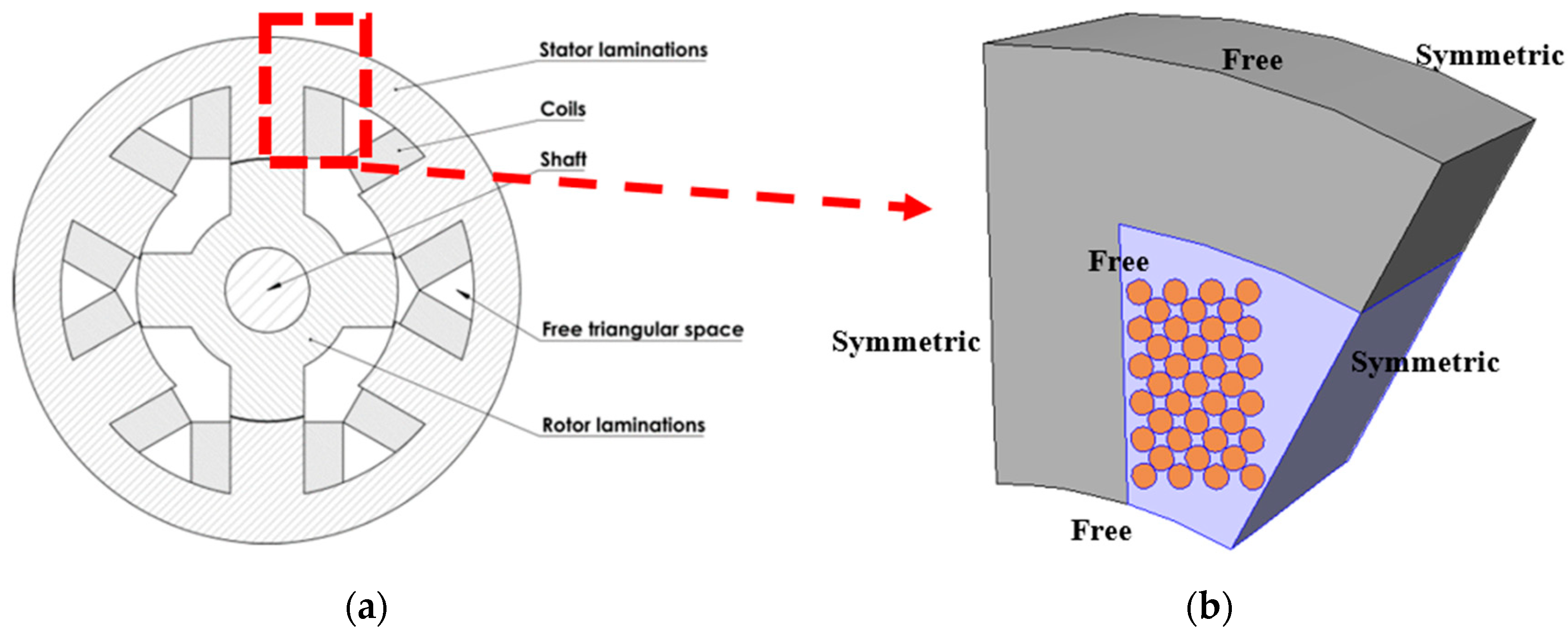
The thermally induced mechanical stress in the stator windings of an electrical machines is investigated numerically using the Comsol Multiphysics software. Three-dimensional thermo-structural simulations are performed for this purpose. A stator of a 6-pole switched reluctance machine is used as a test case in the study, the 2D cross-section of which is shown in Figure 2. The most relevant geometrical dimensions of the machine are listed in Table 1.
Modeling electrical machines in 3D is itself a cumbersome task. The problem becomes more complex if all wires in the winding are to be included in the model. Therefore, to simplify the task, the geometry in this study is subjected to some simplifications which are as follows: (1) only a segment of the stator is modeled, (2) only half of the effective axial length of the machine is used in the simulations, (3) the number of turns of copper wires is reduced to 39 and (4) the enamel coatings of the copper wires are not included in the model. The geometry used in the study is shown in Figure 2. Notice that the winding has a rectangular cross section, and does not follow the curvature of the stator yoke, as is shown in Figure 2b. The reason is that in the experimental setup (Section 6), the winding is made as a form coil with rectangular cross-section, as is common practice for machines with concentrated windings.
The magnetic material grade is N020. The epoxy resin used is Epoxylite TSA 220 (Elantas Europe GmbH, Hamburg, Germany). Type M, enameled copper wire with temperature index of 210 has been considered. Table 2 lists the relevant material properties of the materials used in the simulations and experiments.
The model used in the study can be considered as a combined thermo-structural model. It is considered combined in a sense that first, a temperature distribution over the entire volume is calculated by solving a thermal model; then, the computed temperature is used as an input in the structural model.
The boundary conditions used in the structural model are very important for accurate computation of the stress. A symmetric boundary condition has been used on adjacent sides in the circumferential direction. Since only half of the axial length is used in the simulations, the back face of the geometry has also been modeled with a symmetric boundary, while the front face is free to move. In addition, the upper and lower face along the radial direction are also modeled as free to move. The boundary conditions used in the simulation are more clearly illustrated figuratively in Figure 2. The finite element mesh consists of 2,286,687 tetrahedral elements.
The mechanical stress in the stator core, copper wires and epoxies are determined for two different cases: Case I: Uniform temperature distribution and Case II: Non-uniform temperature distribution. The results and discussion for both the cases are presented in the following sections. The stress is shown as the von-Mises stress, which is calculated as
where σ11, σ22, and σ11 are the tensile stress coefficients which act along the axes and σ12, σ23, and σ11 represent the shear stress which act along the planes.
4. Uniform Temperature Distribution
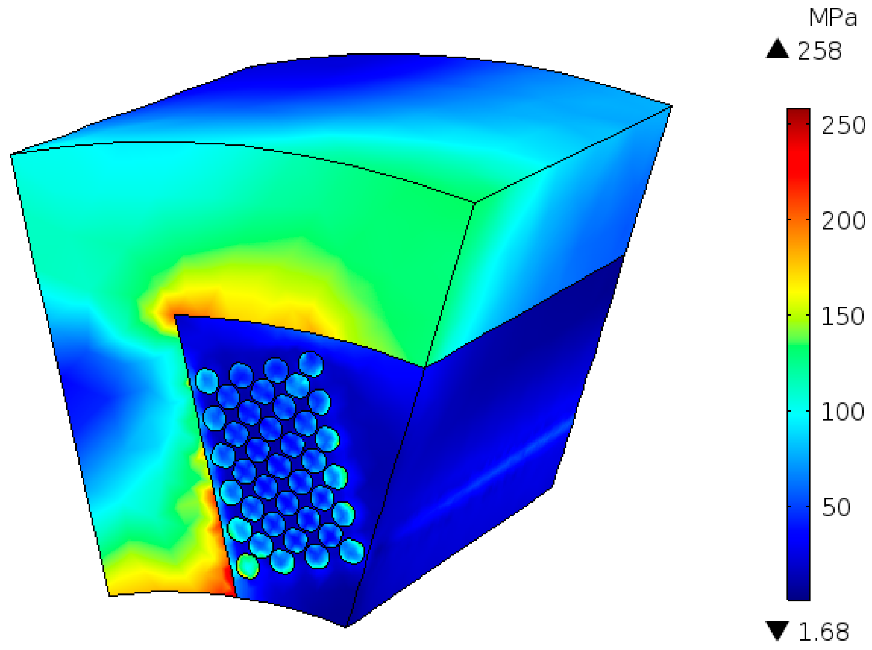
In this case, the temperature throughout the volume is considered to be uniformly distributed. The mechanical stress induced in the stator winding segment is calculated for a uniform temperature distribution of 150 °C. The von-Mises stress distribution over the entire volume is shown in Figure 3. The stress is relatively higher in the regions close to the interface of two materials. This is due to the difference in the coefficient of thermal expansion of the materials. For instance, in Figure 3, the areas of the stator tooth close to the windings have high stress, due to the difference in the coefficient of thermal expansion of the iron and epoxy in the windings. The stress is more concentrated towards the bottom corner of the tooth and the copper wire in the vicinity because of the deformation caused by the expansion.
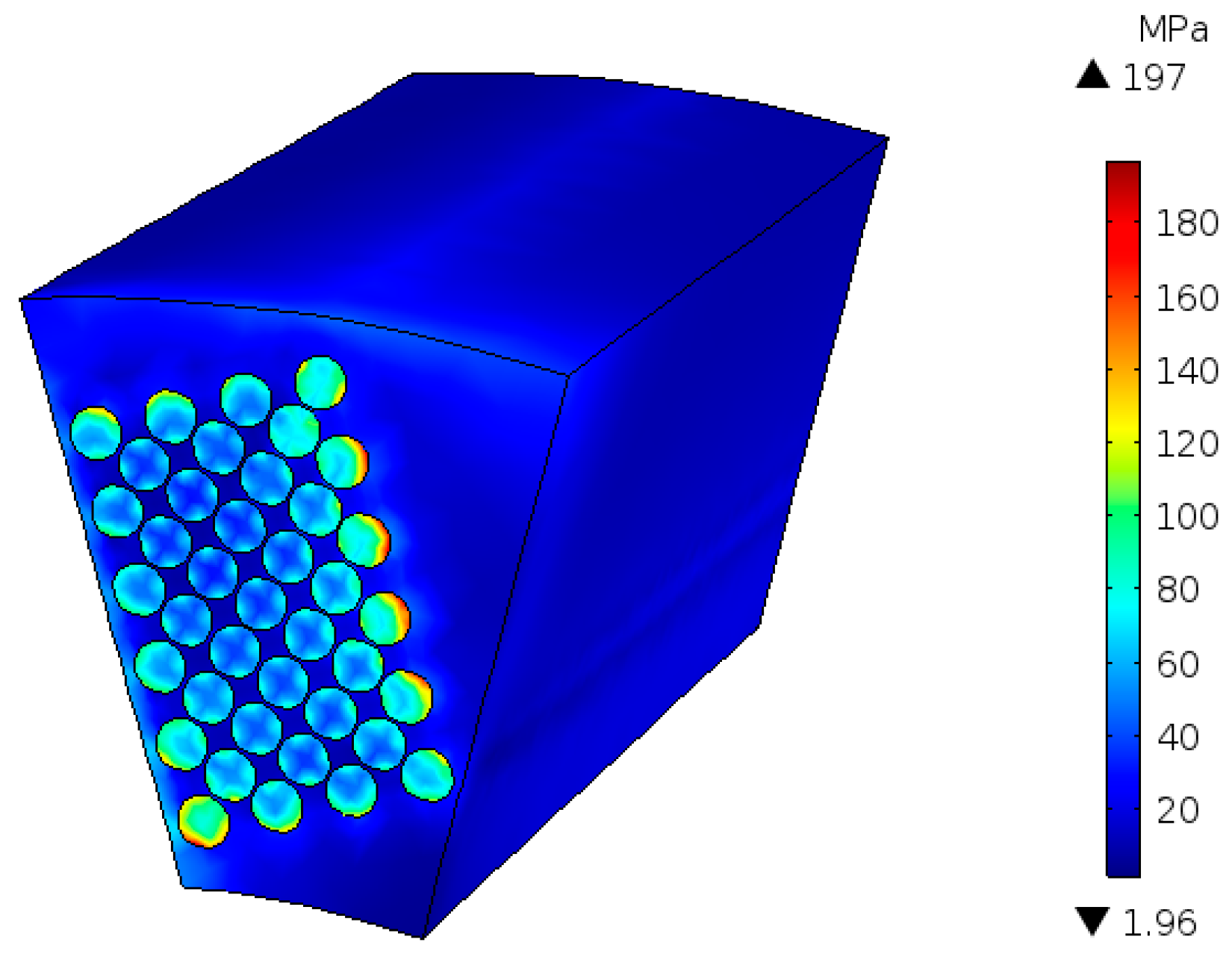
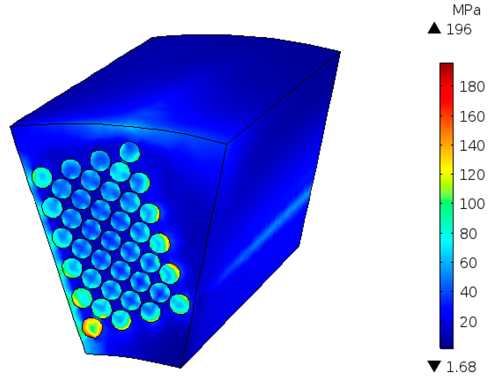
The stress in the copper wires together with the epoxy is shown in Figure 4. The wires on the outer layer are seen to have relatively higher stress compared to the ones in the middle layers. This is probably because the copper wires in the middle are symmetrically surrounded by the epoxy. Therefore, the expansion caused by heating is symmetrically distributed around the wires in the middle layers. However, in the inner layer and the outer layer, the expansion is not symmetric because the inner layer is close to the tooth and the outer layer is exposed to a large volume of epoxy.
This can also be noticed in Figure 5, which shows the stress distribution in the epoxy at different axial positions. In Figure 5, the stresses in the epoxy around the copper wires of inner and outer layers are relatively higher than those in the epoxy around the middle layer wires. Moreover, the stress on the upper half of the epoxy is higher on the front face, while on the lower half, the stress is seen to increase along the axial length. This is also related to the boundary conditions, as the front face and the top boundary are modeled as free to move boundaries causing lower stress due to the deformation, while the back face has a fixed boundary condition which leads to high stress.
The main aim of this study is to investigate the stress on the windings. Therefore, it is important to note the magnitude of the stress on the windings, which consists of the copper wires and the epoxy. From Figure 4, it can be seen that the winding can undergo a stress up to 197 MPa. This is a quite high value especially if we consider the coatings of the copper wire. Usually, copper wires are coated with polymers like Polyamide-imide, the tensile strength of which is about 250 MPa. The thermal expansion coefficient of Polyamide-imide is around the same value as copper. Therefore, the coating would undergo similar stress as the copper wires. Few cycles of such high stress could easily lead to the failure of the wire insulation. Although 197 MPa is the maximum stress that could occur in the winding, not all the wires are exposed to such stress. The average of the stresses in all the wires is about 44 MPa.
On the epoxy alone, the stress can reach as much up to 69 MPa, as seen in Figure 5. This magnitude is much lower than the stress in the iron and copper seen in Figure 3 and Figure 4. Nevertheless, it is still significant when compared to the tensile strength of the epoxy. Consequently, it could also lead to fatigue and breakdown of the epoxy. It can be understood from these results that high temperatures in the machine is responsible not only for the breakdown of the wire insulation due to oxidization, but also induces mechanical stress that could lead to the degradation of the insulation and the epoxy ultimately leading to the failure of the winding.
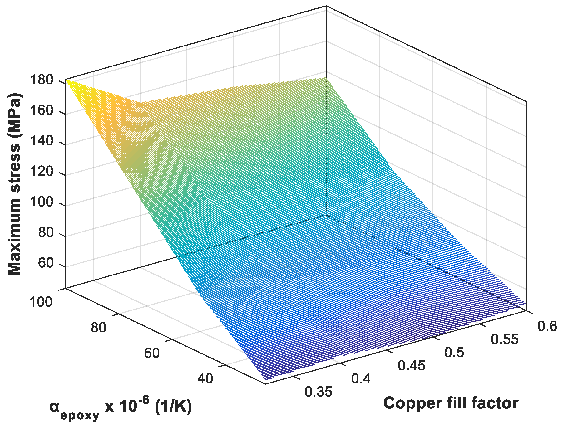
To get more assessment of the thermally induced mechanical stress, additional parametric studies were done. The parameters are the copper fill factor and the coefficient of thermal expansion of the epoxy (αepoxy). A uniform temperature of 150 °C was used in the simulations. In the results shown in Figure 3, Figure 4 and Figure 5, the copper fill factor was 0.6 and the thermal expansion coefficient of the epoxy was 50 × 10−6 (1/K). The parameter values used in the parametric studies are listed in Table 3. The maximum stress on the copper wire in the middle of the winding and the epoxy is plotted as a function of the copper fill factor and αepoxy in Figure 6 and Figure 7, respectively.
From Figure 6, it can be seen that the stress on the copper wire in the middle of the winding increases with increasing αepoxy. Among the four copper fill factor values used in the simulations, the stress is seen to be minimal when the copper fill factor is 0.5 and this holds true for all the αepoxy. Figure 7 shows that the stress on the epoxy also increases with increasing αepoxy. At lower values of αepoxy, increasing the copper fill factor does not seem to have much effect on the stress on the epoxy, but at higher αepoxy, the stress is reduced when the copper fill factor is increased. For instance, for αepoxy = 100 × 10−6 (1/K), when the copper fill factor is increased from 0.32 to 0.6, the maximum stress on the epoxy is decreased by about 25%.
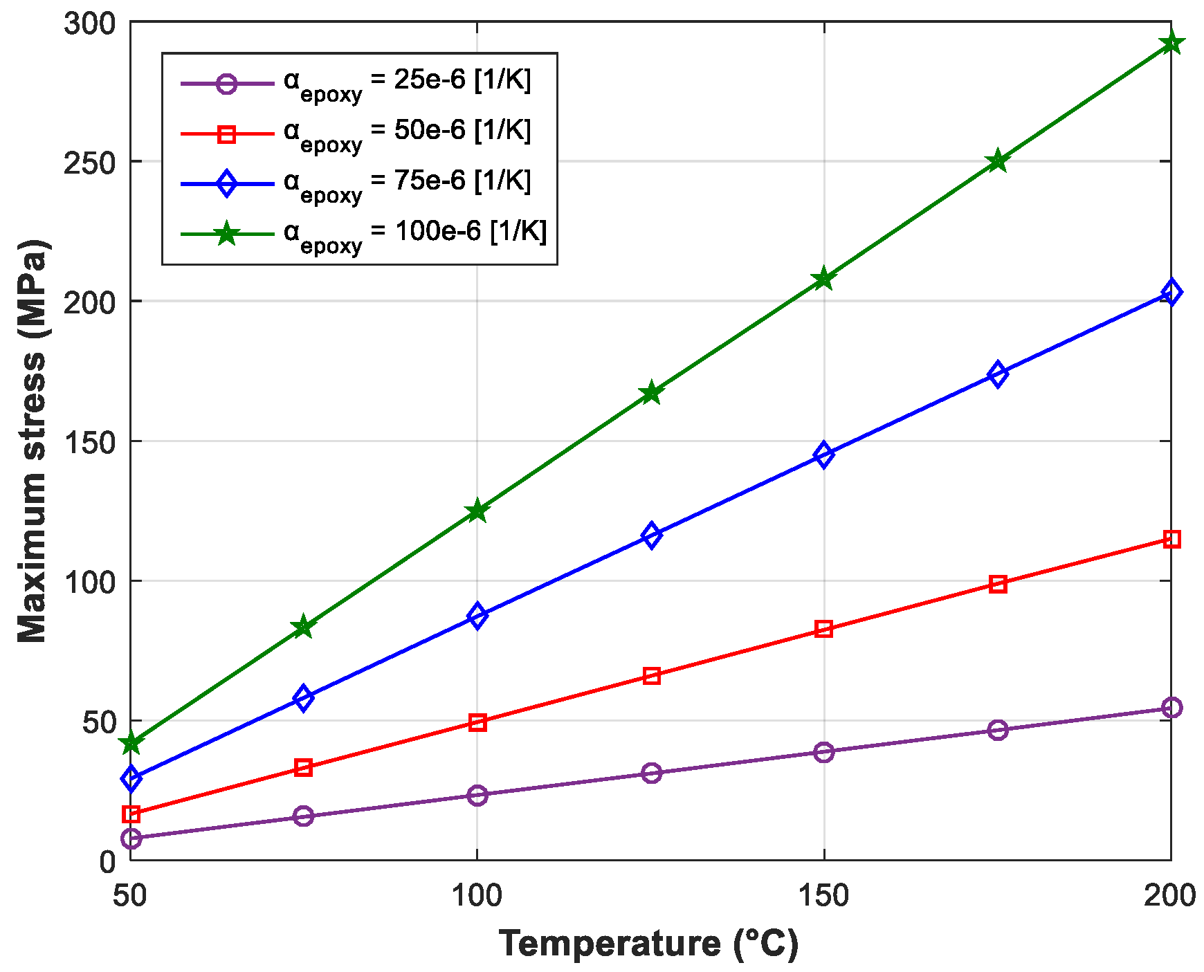
The thermally induced mechanical stress not only depends on the difference in coefficient of thermal expansion of different materials, as seen from the results above, but also on the temperature change. This can also be understood from (1). Next, the maximum stress induced is studied as a function of the temperature. For this, several simulations are performed with different uniform temperature levels ranging from 50 to 200 °C at an interval of 25 °C. The results are shown in Figure 8 and Figure 9, for a copper fill factor of 0.5. In Figure 8, the maximum stress experienced by the copper wire in the middle of the winding is plotted against the temperature for different values of αepoxy. Figure 9 shows the maximum stress on the epoxy plotted against the temperature. The simulated results show that the stress increases linearly with temperature. This is obvious because both the thermal expansion coefficient and the Young’s modulus of the epoxy are assumed to be constant for all the temperature levels in the simulations. But in reality, one or both of these parameters might depend on the temperature.
5. Non-Uniform Temperature Distribution
Next, the thermally induced mechanical stress is studied when the stator winding segment is subjected to a non-uniform temperature distribution. The simulation procedure is the same as above. First, the thermal model is solved to obtain the temperatures in the overall volume. For this, the copper wires are treated as a heat source with a loss density of 4.1 × 10⁶ W/m3, which corresponds to the copper loss of 242 W, based on the result of a previous thermal analysis performed on the same machine [28]. The convective heat transfer coefficient is defined on the outer and the inner surfaces of the stator winding segment, based on literature [28,29]. The outer surface is considered as water cooled, with water inlet temperature 40 °C where as for the inner surface, the heat transfer coefficient is calculated based on the empirical formulas derived in Reference [29]. The adjacent sides in the circumferential direction and the rear back-face side in the axial direction are assigned with symmetric boundary conditions. The resulting temperature distribution is shown in Figure 10, which is evidently non-uniform. Then the temperature computed in the overall volume is used as an input to the structural model.
The boundary conditions in the structural model remain the same as in the previous section, also shown in Figure 2. The von-Mises stress distribution on the entire volume is shown in Figure 11. The distribution of the stress is similar to the previous case (see Figure 3). Again, the area of the stator tooth close to the windings have high stress, due to the difference in the coefficients of thermal expansion and also near the bottom corner of the tooth and the copper wire in the vicinity because of the deformation caused by the expansion.
The stress in the windings (copper wires + epoxy) is shown in Figure 12, while the stress in the epoxy at different axial positions is shown in Figure 13. The stress distribution is similar to the previous case. The stress is relatively higher in the region between the tooth and inner layers of the winding. The stress in the region around the middle layers of wires remains small for the same reason as explained in the previous section.
Although the distribution of the stress is similar to the previous case, the magnitude of the stress is relatively higher in the tooth-winding interface. This is due to the fact that in this case, in addition to the mismatch of the coefficient of thermal expansion, the tooth and the windings are exposed to different temperature levels.
In the model that results in Figure 10, Figure 11, Figure 12 and Figure 13, the copper fill factor used is 0.6 and αepoxy is 50 × 10−6 (1/K). Next, parametric studies based on the parameters of Table 3 are performed for the non-uniform temperature distribution. The results are shown in Figure 14 and Figure 15. It is evident from both figures that the epoxy with low thermal expansion coefficient reduces stress significantly for all given copper fill factors. The increase in the copper fill factor is seen to have a slight effect on the stress on the copper wire in the middle of the winding, with the minimum stress being at the copper fill factor of 0.50. On the epoxy, the stress has a decreasing trend with increasing copper fill factor for all αepoxy, except at 25 × 10−6 (1/K).
6. Measurement of Stress on a Segmented Stator Winding Set-Up
In order to get an experimental assessment, the stress on a segmented stator winding is measured. The set-up consists of one stator tooth of the switched reluctance machine, the parameters of which are listed in Table 1.
The construction of the set-up is explained figuratively in Figure 16. A concentrated winding with 36 turns in enameled copper wire of 0.9 mm diameter, with a fixed width between each turn, is wounded around the tooth. The reason for choosing a low number of turns with a fixed distance between each turn is twofold. First, it allows us to obtain a better accuracy in positioning the wires in the experimental set-up. Secondly, the 3D numerical model is easier to solve with a rather low number of thick copper wires than with many very thin wires. Both arguments allow us to validate the stress computed from the numerical model more accurately. As explained in section 2, the winding has a rectangular cross-section, and does not follow the curvature of the stator yoke, as is shown in Figure 2b. The winding in the set-up is impregnated with Epoxylite TSA 220S epoxy resin. To measure the stress, two strain gauge sensors are installed on the iron surface at one end of the set-up as shown in Figure 16(2). The strain gauge sensor installed on the tooth side is denoted by Sensor 1 and the strain gauge sensor installed on the yoke side is Sensor 2.
The segmented stator winding set-up is then placed in a thermally insulated box. The winding of the set-up is fed with 5 A dc. The stress is measured at different temperature levels. Two PT100 temperature sensors are installed in the set-up, one inside the winding and other on the outer epoxy surface. The dSpace module is used for data acquisition. The complete experimental set-up is shown in Figure 17.
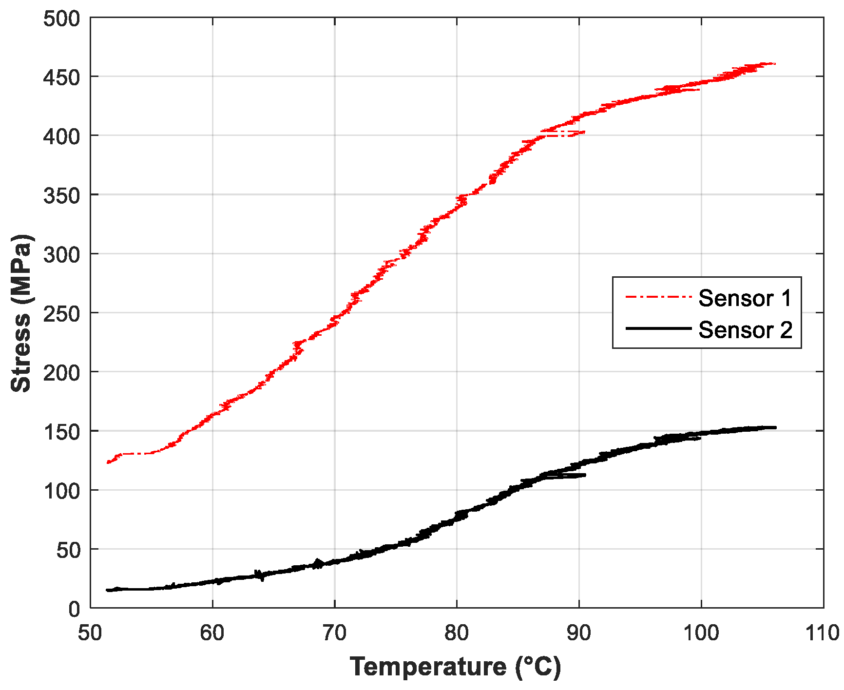
As the current is supplied in the copper wires, the temperature in the set-up starts to rise. Figure 18 shows temperature rise in the two locations were the PT100 sensors are installed. The current was switched off when the temperature inside the winding reached around 106 °C. From the data acquired through the strain gauge sensors, the von-Mises stress is determined. In Figure 19, the von-Mises stresses measured by the two sensors are plotted as a function of the temperature inside the winding. The stress measured by Sensor 1 is very high, 3–5 times higher compared to the stress measured by Sensor 2. One crucial thing to note is the non-linear behavior of the measured stress. This could be because in reality the coefficient of the thermal expansion of the epoxy could be non-linear. Although some literature reporting the non-linear thermal expansion in Aluminum alloys [30] and carbon/epoxy laminated composites [31] exist, no report was found on the behavior of epoxy resin itself. Moreover, very little data was available about the properties of the epoxy used in the measurement. Nevertheless, it is evident from the measured results that the stress increases with the increase in the temperature.
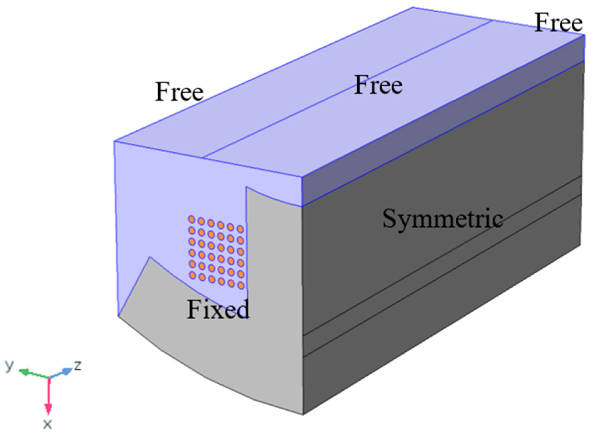
A numerical model with the geometry and the boundary condition identical to the segmented stator winding used in the experimental set-up is developed in Comsol for validation purposes. The geometry of the new model is shown in Figure 20, together with the boundary conditions used in the structural analysis. In the experiment, the set-up has a mechanically fixed surface at the end where the strain gauge sensors are installed. Therefore, one of the end surfaces (front face) in the numerical model is also modeled with a fixed boundary condition. The end windings are neglected in the numerical model. Since only one of the end surfaces is fixed, the possibility of using half the axial length with a symmetric boundary condition ceases. Therefore, a full active length of the stator tooth is used in the simulation, with a free to move boundary condition at the rear face. The model is symmetric along the XY plane. The outer surface of the epoxy is also modeled as free to move.
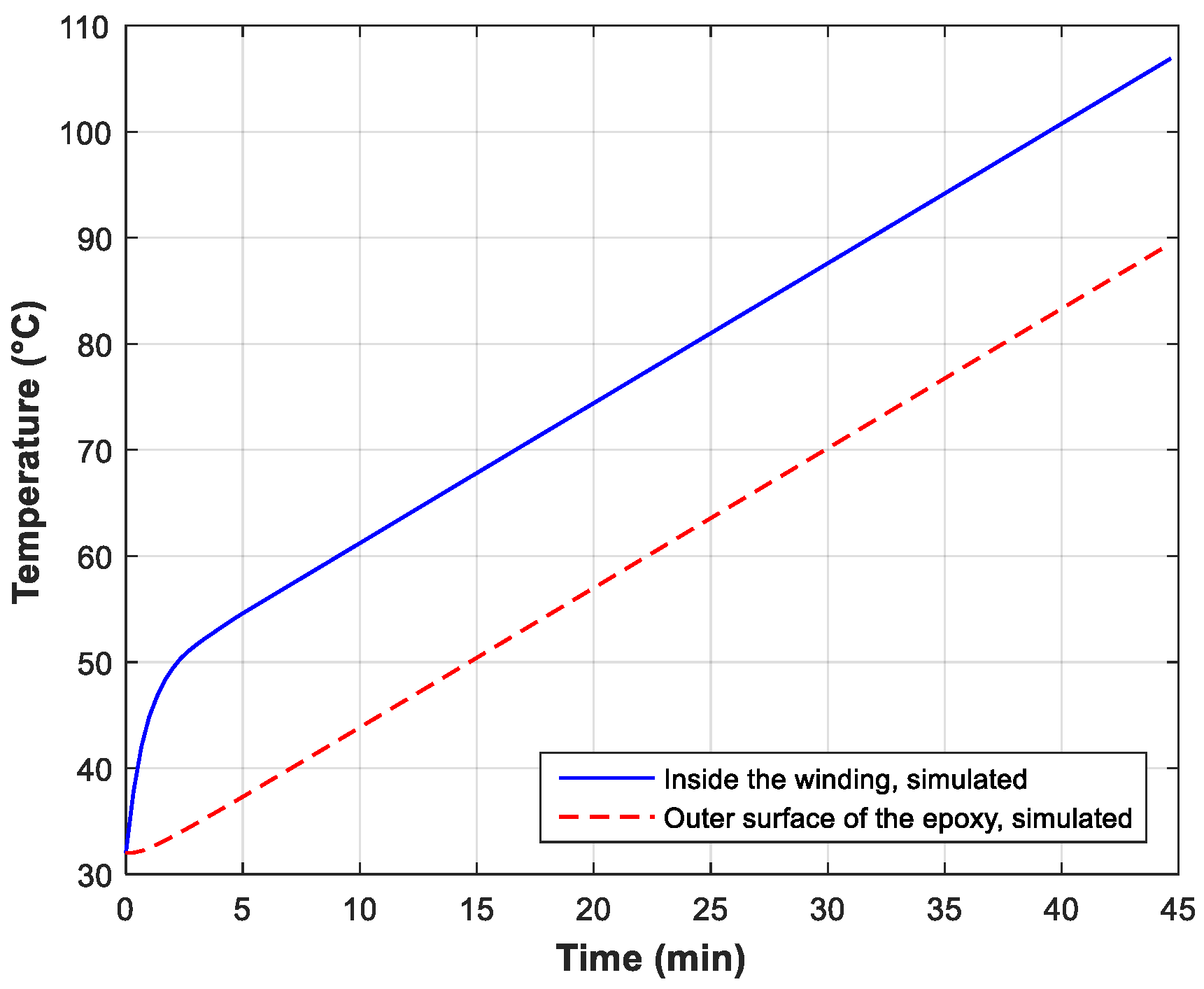
The simulation procedure is the same as described in the previous sections. First, the thermal model is solved to obtain a temperature distribution. In this case, a time-dependent temperature distribution in the overall volume is obtained. The temperatures calculated at the location of the two PT100 temperature sensors are shown in Figure 21. Although the temperature rise in the simulation is fast compared to the measurement, the time-evolution of the temperature and the difference between the temperatures inside the winding and the outer surface of the epoxy is identical to that obtained from the measurement.
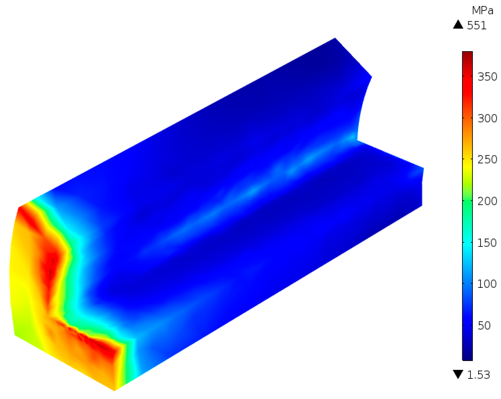
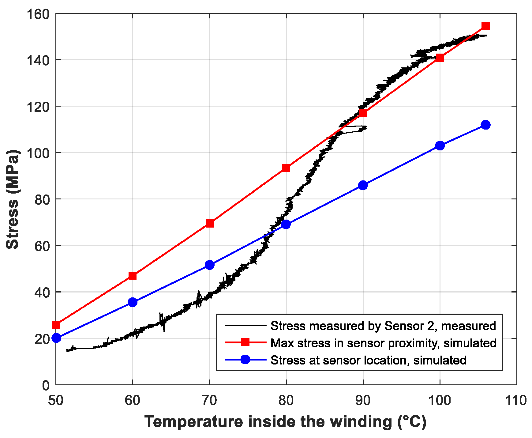
The structural simulations are performed for discrete temperature levels and the stresses are obtained. Figure 22 shows the stress distribution obtained for the case when the temperature inside the winding is 106 °C. It is clear that the stress is more concentrated towards the end where the sensors are installed (towards the front face). Figure 23 shows the comparison between the simulation and the measurement. In this figure, the black line shows the stress measured by Sensor 2 installed on the yoke-side iron surface, the blue line shows the von-Mises stress computed at the sensor location and the red line shows the maximum von-Mises stress obtained in the proximity of the sensor location (in the center of the yoke-side surface close to the front face). The experimental reading from Sensor 2 shows a non-linear behavior whereas the simulated results are linear, causing discrepancies between the results. In Figure 22, it can be seen that the order of the magnitude of the stress is the same on both the tooth-side surface and the yoke-side surface. Therefore, comparing the simulated stress on the tooth-side with the stress measured by the Sensor 1 will have higher discrepancies.
Other than the possible non-linear thermal expansion properties of the material used in the measurements as the main reason, some discrepancies between the measured and the simulated results can also be explained as follows:
- (1)
- Set-up construction: Several cracks were seen in the outer epoxy surface, which can also be seen in Figure 16(4), forming after the curing process. Although this outer surface is quite far from the stress sensors, it may influence the temperature and stress distribution inside the windings. In addition, the position of the wires shows small deviations from the positions in the simulation (visible in Figure 16(3)), and hence the distribution of the epoxy is also influenced.
- (2)
- Assumptions in the numerical model: The end-winding region has been neglected in the numerical model. In real motors, the end-windings of the stator are not epoxy impregnated. However, in the experimental set-up, the end winding region has also been impregnated with epoxy. Neglecting this certainly affects the stress computed in the simulation. Also, the actual fixed surface in the experimental set-up is the surface of the epoxy beneath the end-windings, but the numerical model is simplified by fixing one of the axial sides of the tooth.
- (3)
- Inaccuracies in the measurement: The tolerances of the sensors together with tolerances of the components in the conditioning circuits could introduce slight errors in the measured results.
7. Conclusions
In this paper, an effort has been made to quantify the mechanical stress induced in the windings of an electrical machine due to high temperatures. This is done numerically by performing thermo-structural simulations on a segmented stator winding geometry. The simulation results are presented for both uniform and non-uniform temperature distributions in the geometry. Results show high stress in the epoxy and also in the copper wires. If the temperature is very high, the stress can reach well beyond the yield and tensile strength of the polymer coatings, which could lead to failure. Parametric studies show that the stress could be reduced by increasing the copper fill factor and using an epoxy with low thermal expansion coefficient. Measurement of stress on a segmented stator winding set-up resulted in stress comparable to that obtained from the simulations, although discrepancies were observed. Nevertheless, the measurements highlighted the non-linear thermal expansion behavior of the materials used.
Author Contributions
B.S. developed the numerical models, performed the simulations and experimental works, analyzed the results and wrote the manuscript. P.S. provided comments and suggestions during the development of the models and measurement set-up and also revised the manuscript.
Funding
This research was supported by Flanders Make, in the framework of the Hipercool project.
Acknowledgments
The authors would like to thank Nils Clarie for helping with the PCB design for the conditioning circuit and Abdalla Hussein Rashad Mohamed for assisting in the experimental work.
Conflicts of Interest
The authors declare no conflict of interest.
References
- Lemmens, J.; Driesen, J.; Vanassche, P. Thermal management in traction applications as a constraint optimal control problem. In Proceedings of the IEEE Vehicle Power and Propulsion Conference, Seoul, Korea, 9–12 October 2012; pp. 36–41. [Google Scholar]
- Bonnett, A.H.; Soukup, G.C. Cause and analysis of stator and rotor failures in three-phase squirrel-cage induction motors. IEEE Trans. Ind. Appl. 1992, 28, 921–937. [Google Scholar] [CrossRef]
- Huang, Z. Modeling and testing of insulation degradation due to dynamic thermal loading of electrical machines. Ph.D. Thesis, Lund University, Lund, Sweden, 2017. [Google Scholar]
- Zoeller, C.; Vogelsberger, M.A.; Fasching, R.; Grubelnik, W.; Wolbank, T.M. Evaluation and current-response-based identification of insulation degradation for high utilized electrical machines in railway application. IEEE Trans. Ind. Appl. 2017, 53, 2679–2689. [Google Scholar] [CrossRef]
- Zhang, Y.; McLoone, S.; Cao, W.; Qiu, F.; Gerada, C. Power loss and thermal analysis of a MW high-speed permanent magnet synchronous machine. IEEE Trans. Energy Convers. 2017, 32, 1468–1478. [Google Scholar] [CrossRef]
- Qui, Y.; Zhang, W.; Cao, M.; Feng, Y.; Infield, D. An electro-thermal analysis of a variable-speed doubly-fed induction generator in a wind turbine. Energies 2015, 8, 3386–3402. [Google Scholar]
- Kavanagh, D.; Howey, D.; McCulloch, M. An applied laboratory characterization approach for electric machine insulation. In Proceedings of the 9th IEEE International Symposium on Diagnostics for Electric Machines, Power Electronics and Drives, Valencia, Spain, 27–30 August 2013. [Google Scholar]
- Pan, T.-Y. Thermal cycling induced plastic deformation in solder joints—Part II: Accumulated deformation in through hole joints. IEEE Trans. Compon. Hybrids Manuf. Technol. 1991, 14, 824–832. [Google Scholar] [CrossRef]
- Baker, E. Some effects of temperature on material properties and device reliability. IEEE Trans. Parts Hybrids Packag. 1972, 8, 4–14. [Google Scholar] [CrossRef]
- Seo, S.-H.; Hwang, J.-S.; Yang, J.-M.; Hwang, W.-J.; Song, J.-Y.; Lee, W.-J. Failure mechanism of copper through-silicon vias under biased thermal stress. Thin Solid Films 2013, 546, 14–17. [Google Scholar] [CrossRef]
- Selvanayagam, C.S.; Lau, J.H.; Zhang, X.; Seah, S.K.W.; Vaidyanathan, K.; Chai, T.C. Nonlinear thermal stress/strain analyses of copper filled TSV (Through Silicon Via) and their flip-chip microbumps. IEEE Trans. Adv. Packag. 2009, 32, 720–728. [Google Scholar] [CrossRef]
- Keller, R.R.; Monig, R.; Volkert, C.A.; Arzt, E.; Schwaiger, R.; Kraft, O. Interconnect failure due to cyclic loading. In Proceedings of the Stress-Induced Phenomena in Metallization: Sixth International Workshop, Ithaca, NY, USA, 25–27 July 2002; American Institute of Physics: College Park, MD, USA, 2002; pp. 119–132. [Google Scholar]
- Shen, Y.-L. Analysis of thermal stresses in copper interconnect/Low-k dielectric structures. J. Electron. Mater. 2005, 34, 497–505. [Google Scholar] [CrossRef]
- DeMilo, C.; Bergad, C.; Forni, R.; Brukilacchio, T. Thermally induced stresses resulting from coefficient of thermal expansion differentials between an LED sub-mount material and various mounting substrates. Proc. SPIE 2007, 6486, 64860N. [Google Scholar]
- Hao, X.; Qin, L.; Yang, D.; Liu, S. Thermal-mechanical stress and fatigue failure analysis of a PBGA. In Proceedings of the 5th International Conference on Electronic Packaging Technology, Shanghai, China, 28–30 October 2003. [Google Scholar]
- Li, W.; Zhang, X. Thermal-mechanical failure and life analysis on CBGA package used for great scale FPGA chip. In Proceedings of the International Conference on Electronic Packaging Technology High Density Packaging, Beijing, China, 10–13 August 2009. [Google Scholar]
- Hsueh, E.Y.S.C.H.; Becher, P.F. Analyses of thermal expansion behavior of intergranular two-phase composites. J. Mater. Sci. 2001, 36, 255–261. [Google Scholar] [CrossRef]
- Yuan, Q.; Endoh, R.; Ima, T.; Kajita, Y.; Luo, Y. Failure mode verification of power IGBT under different thermal stress application conditions in power cycling test environment. In Proceedings of the International Conference on Electronics Packaging and iMAPS All Asia Conference (ICEP-IAAC), Mie, Japan, 17–21 April 2018; pp. 367–370. [Google Scholar]
- Pedersen, K.B.; Pedersen, K. Dynamic modeling method of electro-thermo-mechanical degradation in IGBT modules. IEEE Trans. Power Electron. 2016, 31, 975–986. [Google Scholar] [CrossRef]
- Tseng, H.-K.; Wu, M.-L. Electro-thermal-mechanical modeling of wire bonding failures in IGBT. In Proceedings of the 8th International Microsystems, Packaging, Assembly and Circuits Technology Conference, Taipei, Taiwan, 22–25 October 2013. [Google Scholar]
- IEEE. IEEE Guide for Insulation Maintenance of Electric Machines—Redline; IEEE Std 56-2016; IEEE: New York, NY, USA, 2016; pp. 1–233. [Google Scholar]
- Wood, J.W. Mechanical stresses in rotating machines and insulation design considerations. In Proceedings of the IEE Colloquium on Mechanical Influence on Electrical Insulation Performance, London, UK, 28 February 1995. [Google Scholar]
- Weiers, T.; Keller, D.; Vogelsang, R. The Impact of low Amplitude 100 Hz Vibrations on the Winding Insulation of Rotating High Voltage Machines. In Proceedings of the 14th International Symposium on High Voltage Engineering (ISH 2005), Beijing, China, 25–28 August 2005. [Google Scholar]
- Griffith, G.; Tucker, S.; Milsom, J.; Stone, G. Problems with modern air-cooled generator stator winding insulation. IEEE Electr. Insul. Mag. 2000, 16, 6–10. [Google Scholar] [CrossRef]
- Huang, Z.; Reinap, A.; Alakula, M. Degradation and fatigue of epoxy impregnated traction motors due to thermal and thermal induced mechanical stress—Part I: Thermal mechanical simulation of single wire due to evenly distributed temperature. In Proceedings of the 8th IET International Conference on Power Electronics, Machines and Drives (PEMD), Glasgow, UK, 19–21 April 2016. [Google Scholar]
- Huang, Z.; Reinap, A.; Alakula, M. Degradation and fatigue of epoxy impregnated traction motors due to thermal and thermal induced mechanical stress—Part II: Thermal mechanical simulation of multiple wires due to evenly and unevenly distributed temperature. In Proceedings of the 8th IET International Conference on Power Electronics, Machines and Drives (PEMD), Glasgow, UK, 19–21 April 2016. [Google Scholar]
- Kulan, M.C.; Baker, N.J.; Widmer, J.D. Design of a high fill factor permanent magnet integrated starter generator with compressed stator windings. In Proceedings of the XXII International Conference on Electrical Machines (ICEM), Lausanne, Switzerland, 4–7 September 2016; pp. 1513–1519. [Google Scholar]
- Nonneman, J.; Clarie, N.; Jollyn, I.T.; Schlimpert, S.; Sergeant, P.; de Paepe, M. Advanced lumped parameter model for switched reluctance motors with high performance cooling. In Proceedings of the 16th International Heat Transfer Conference, Beijing, China, 10–15 August 2018. [Google Scholar]
- Romanazzi, P.; Howey, D.A. Air-gap convection in a switched reluctance machine. In Proceedings of the Tenth International Conference on Ecological Vehicles and Renewable Energies (EVER), Monte Carlo, Monaco, 31 March–2 April 2015. [Google Scholar]
- Sahroni, T.R.; Sulaiman, S.; Romli, I.; Salleh, M.R.; Ariff, H.A. Nonlinear thermal expansion model for SiC/Al. Int. J. Mech. Mech. Eng. 2011, 5, 1151–1155. [Google Scholar]
- Nawab, Y.; Jacquemin, F.; Casari, P.; Boyard, N.; Borjon-Piron, Y.; Sobotka, V. Study of variation of thermal expansion coefficients in carbon/epoxy laminated composite plates. Compos. B Eng. 2013, 50, 144–149. [Google Scholar] [CrossRef] [Green Version]
Figure 1.
A general representation of a stator slot of an electrical machine with two layers of epoxy impregnated windings.
Figure 1.
A general representation of a stator slot of an electrical machine with two layers of epoxy impregnated windings.

Figure 2.
(a) 2D cross-section of an SR machine and (b) section of the stator with windings considered for the 3D model together with the boundary conditions used in the structural simulations.
Figure 2.
(a) 2D cross-section of an SR machine and (b) section of the stator with windings considered for the 3D model together with the boundary conditions used in the structural simulations.

Figure 3.
The von-Mises stress distribution over the entire volume. Higher stress is seen near iron-epoxy interface, especially in the corner and tooth tip.
Figure 3.
The von-Mises stress distribution over the entire volume. Higher stress is seen near iron-epoxy interface, especially in the corner and tooth tip.
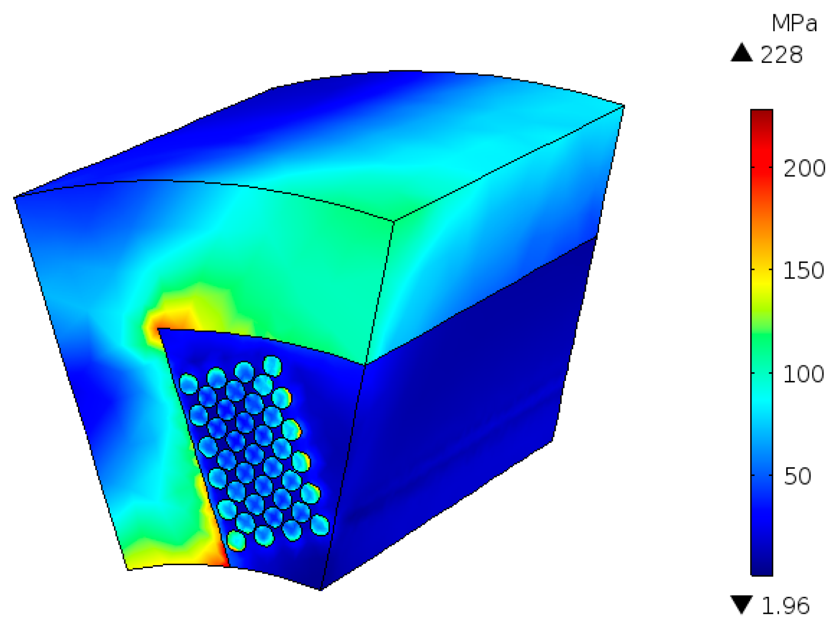
Figure 4.
The von-Mises stress distribution in the winding (copper wires + epoxy).

Figure 5.
The von-Mises stress distribution in the epoxy at three different axial positions: 0, l/2 and l.
Figure 5.
The von-Mises stress distribution in the epoxy at three different axial positions: 0, l/2 and l.
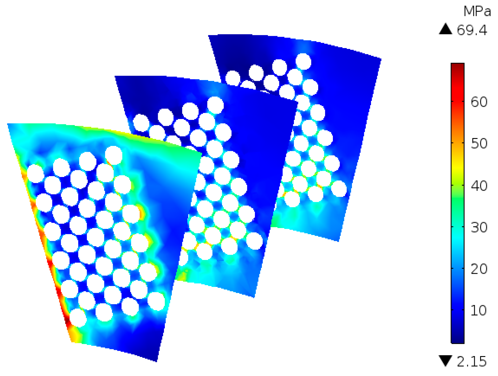
Figure 6.
The maximum stress on the copper wire in the middle of the winding, plotted as a function of the copper fill factor and the coefficient of thermal expansion of the epoxy.
Figure 6.
The maximum stress on the copper wire in the middle of the winding, plotted as a function of the copper fill factor and the coefficient of thermal expansion of the epoxy.
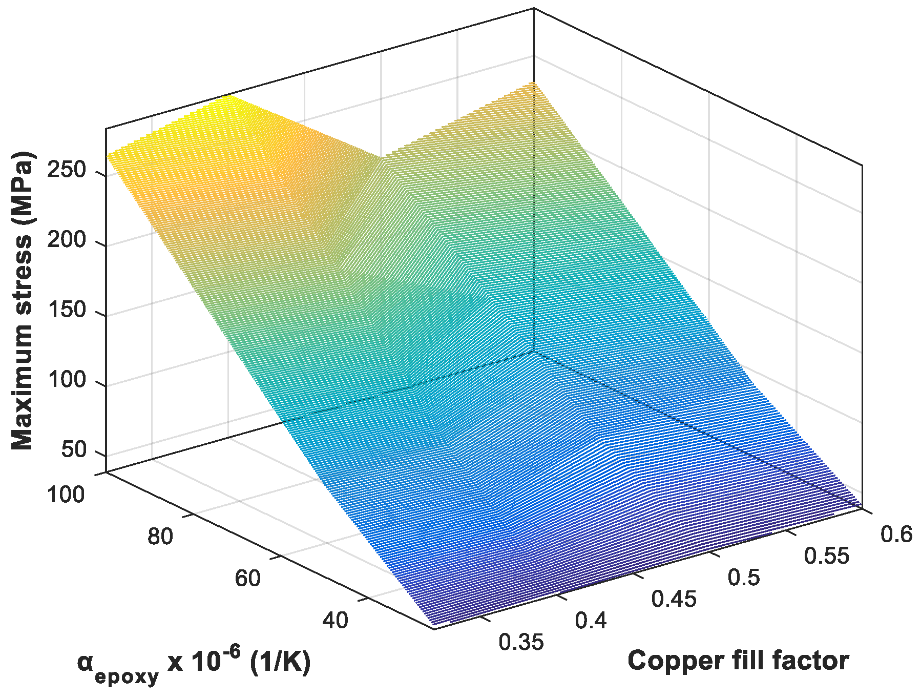
Figure 7.
The maximum stress in the epoxy, plotted as a function of the copper fill factor and the coefficient of thermal expansion of the epoxy.
Figure 7.
The maximum stress in the epoxy, plotted as a function of the copper fill factor and the coefficient of thermal expansion of the epoxy.

Figure 8.
Maximum stress in the copper wire in the middle of the winding, as a function of temperature, for different thermal expansion coefficients of epoxy.
Figure 8.
Maximum stress in the copper wire in the middle of the winding, as a function of temperature, for different thermal expansion coefficients of epoxy.

Figure 9.
Maximum stress in the epoxy as a function of temperature, for different thermal expansion coefficients of epoxy.
Figure 9.
Maximum stress in the epoxy as a function of temperature, for different thermal expansion coefficients of epoxy.
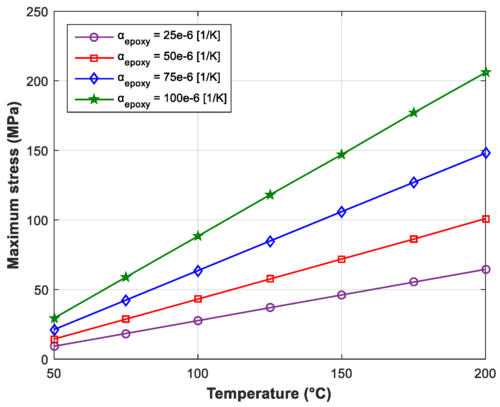
Figure 10.
Non-uniformly distributed temperature obtained from the thermal analysis.
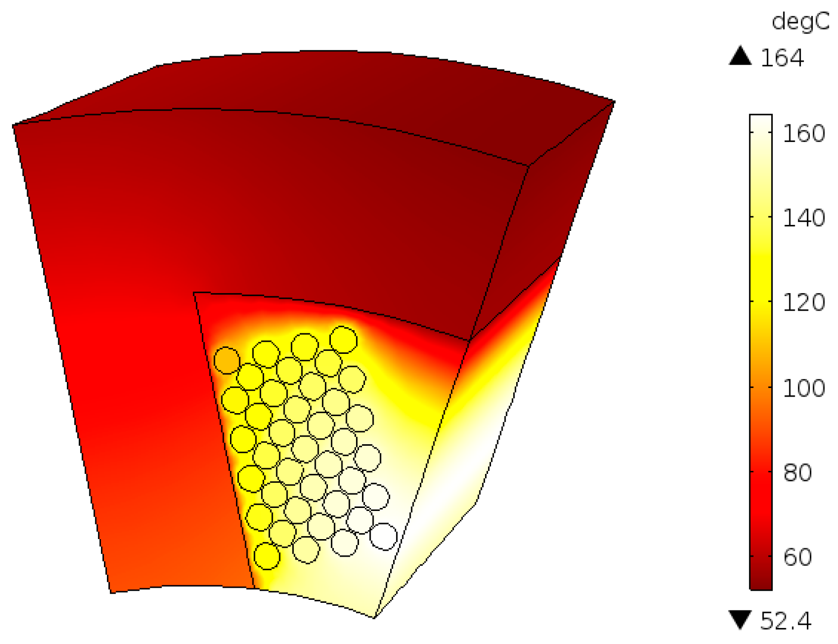
Figure 11.
The von-Mises stress distribution over the stator segment for non-uniform temperature distribution.
Figure 11.
The von-Mises stress distribution over the stator segment for non-uniform temperature distribution.

Figure 12.
The von-Mises stress distribution in the winding for non-uniform temperature distribution.
Figure 12.
The von-Mises stress distribution in the winding for non-uniform temperature distribution.

Figure 13.
The von-Mises stress distribution in the epoxy at three different axial positions: 0, l/2 and l; for non-uniform temperature distribution.
Figure 13.
The von-Mises stress distribution in the epoxy at three different axial positions: 0, l/2 and l; for non-uniform temperature distribution.

Figure 14.
The maximum stress on the copper wire in the middle of the winding, plotted as a function of the copper fill factor and the coefficient of thermal expansion of the epoxy when the temperature distribution is non-uniform.
Figure 14.
The maximum stress on the copper wire in the middle of the winding, plotted as a function of the copper fill factor and the coefficient of thermal expansion of the epoxy when the temperature distribution is non-uniform.

Figure 15.
The maximum stress in the epoxy, plotted as a function of the copper fill factor and the coefficient of thermal expansion of the epoxy when the temperature distribution is non-uniform.
Figure 15.
The maximum stress in the epoxy, plotted as a function of the copper fill factor and the coefficient of thermal expansion of the epoxy when the temperature distribution is non-uniform.

Figure 16.
Construction of the segmented stator winding set-up: (1) 0.9 mm copper wire is wounded, having 36 turns spaced equally; (2) two strain gauges are installed on the stator segment, one beneath the yoke and one along the side of the tooth; (3) the epoxy impregnated winding is placed around the tooth; (4) the remaining space around the winding is also impregnated with epoxy.
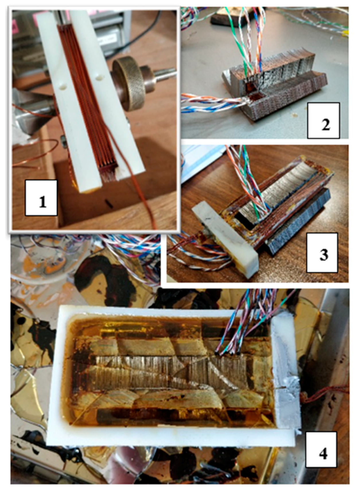
Figure 17.
The complete experimental set-up.
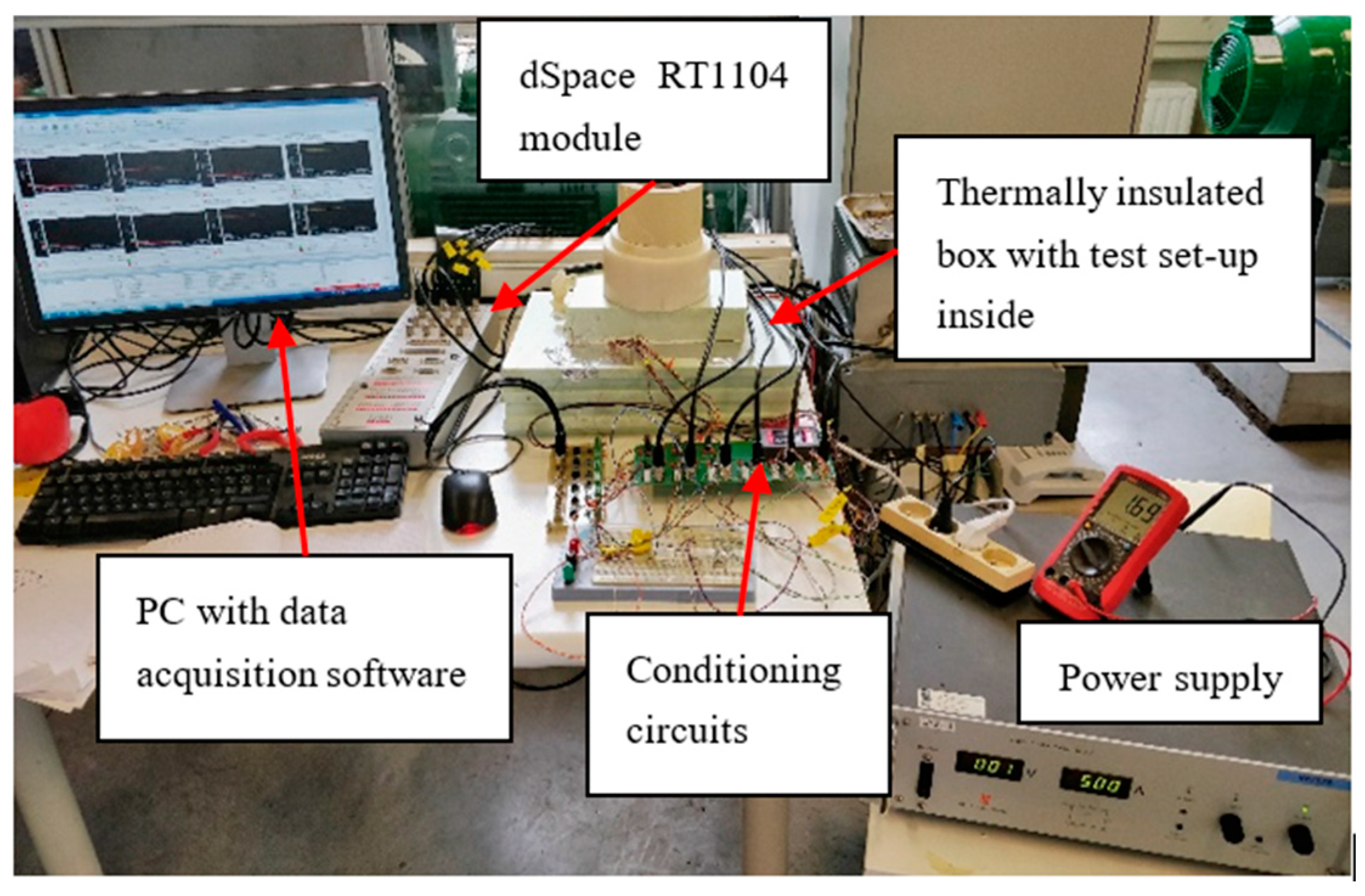
Figure 18.
Temperature measured by the PT100 sensors installed inside the winding and in the outer surface of the epoxy.
Figure 18.
Temperature measured by the PT100 sensors installed inside the winding and in the outer surface of the epoxy.
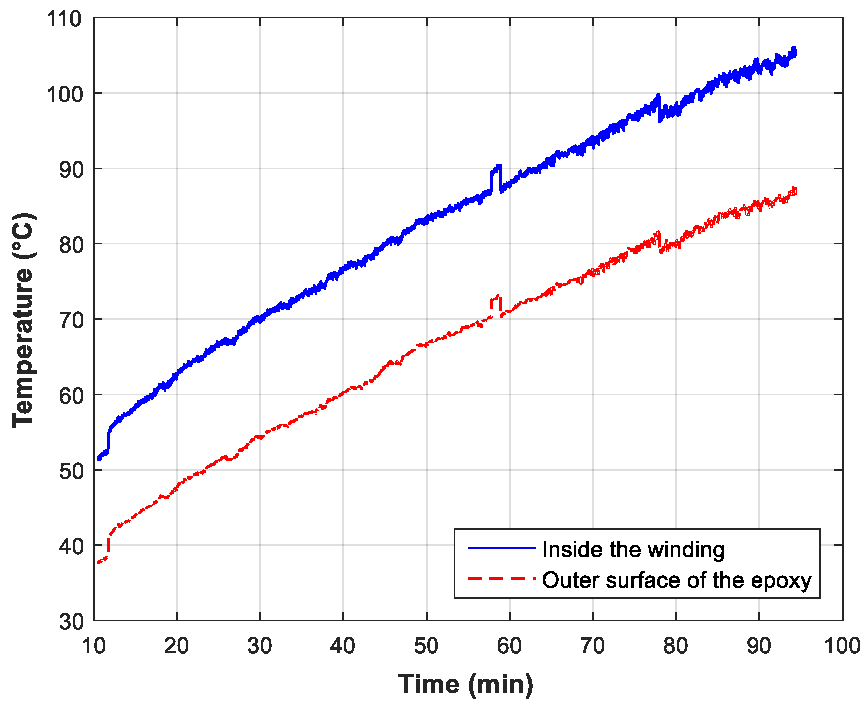
Figure 19.
The von-Mises stress measured by the strain gauge sensors installed in the iron surfaces. Sensor 1: Tooth side, Sensor 2: Yoke side.
Figure 19.
The von-Mises stress measured by the strain gauge sensors installed in the iron surfaces. Sensor 1: Tooth side, Sensor 2: Yoke side.

Figure 20.
The geometry used in the numerical model used for validation.

Figure 21.
Temperature obtained from the simulation, at the two sensor locations.

Figure 22.
The von-Mises stress distribution in the iron when the temperature inside the winding is 106 °C.
Figure 22.
The von-Mises stress distribution in the iron when the temperature inside the winding is 106 °C.

Figure 23.
Comparison between the simulated and the measured stress in the yoke-side surface. The measured stresses are from Sensor 2.
Figure 23.
Comparison between the simulated and the measured stress in the yoke-side surface. The measured stresses are from Sensor 2.


Table 1.
Geometrical dimensions of the machine.
| Parameters | Value |
|---|---|
| Number of stator poles | 6 |
| Outer diameter of stator (mm) | 120 |
| Inner diameter of stator yoke (mm) | 98 |
| Thickness of the tooth (mm) | 17.5 |
| Stack length (mm) | 80 |
| Number of turns per coil | 39 |
Table 2.
Thermal and mechanical properties of the materials.
| Properties | Electrical Sheet (N020) | Copper | Epoxylite TSA 220 |
| Young′s Modulus (Pa) | 200 × 109 | 1.1 × 10¹¹ | 3.5 × 10⁹ |
| Poisson′s Ratio | 0.29 | 0.35 | 0.34 |
| Thermal Conductivity (W/m·K) | 28 | 400 | 0.21 |
| Density (Kg/m3) | 7650 | 8960 | 1180 |
| Heat capacity at constant pressure (J/Kg·K) | 440 | 385 | 400 |
| Coefficient of Thermal Expansion (1/K) | 12 × 10−6 | 18 × 10−6 | 50 × 10−6 |
Table 3.
Value of the parameters used in the parametric studies.
| Parameter | Value | |||
|---|---|---|---|---|
| Copper fill factor | 0.32 | 0.4 | 0.5 | 0.6 |
| α_epoxy (1/K) | 25 × 10−6 | 50 × 10−6 | 75 × 10−6 | 100 × 10−6 |
© 2018 by the authors. Licensee MDPI, Basel, Switzerland. This article is an open access article distributed under the terms and conditions of the Creative Commons Attribution (CC BY) license (http://creativecommons.org/licenses/by/4.0/).
Share and Cite
MDPI and ACS Style
Silwal, B.; Sergeant, P. Thermally Induced Mechanical Stress in the Stator Windings of Electrical Machines. Energies 2018, 11, 2113. https://doi.org/10.3390/en11082113
AMA Style
Silwal B, Sergeant P. Thermally Induced Mechanical Stress in the Stator Windings of Electrical Machines. Energies. 2018; 11(8):2113. https://doi.org/10.3390/en11082113
Chicago/Turabian StyleSilwal, Bishal, and Peter Sergeant. 2018. "Thermally Induced Mechanical Stress in the Stator Windings of Electrical Machines" Energies 11, no. 8: 2113. https://doi.org/10.3390/en11082113
Note that from the first issue of 2016, this journal uses article numbers instead of page numbers. See further details here.