Article

A DC Short-Circuit Fault Ride Through Strategy of MMC-HVDC Based on the Cascaded Star Converter

1
School of Electrical and Power Engineering, China University of Mining and Technology, Xuzhou 221000, China
2
School of Information and control Engineering, China University of Mining and Technology, Xuzhou 221000, China
*
Author to whom correspondence should be addressed.
Energies 2018, 11(8), 2079; https://doi.org/10.3390/en11082079
Submission received: 11 July 2018 / Revised: 1 August 2018 / Accepted: 7 August 2018 / Published: 10 August 2018
(This article belongs to the Section A: Sustainable Energy)

Abstract

:
A modular multilevel converter based high voltage direct current (MMC-HVDC) with DC fault self-clearing is adopted to deal with the DC short-circuit fault. However, the constant power load characteristic of the sub-modules causes capacitor voltages to diverge and the converter to go out of hot standby. To address this problem, a novel DC short-circuit fault ride through strategy is proposed. According to the polarities of grid voltages, the working or blockage of the upper and lower bridge arms is chosen according to six sections to obtain a cascaded star converter. The capacitor voltages of MMC sub-modules are maintained and balanced through the control similar to the cascaded star converter. Moreover, in order not to change zero crossing, a cluster balancing control method by scaling the amplitudes of the modulated waves is proposed to balance the capacitor voltages between phase clusters. The strategy also achieves the DC Bus line-to-line equipotential and no fault current generated. With the switches of two modes (normal operation and fault ride through operation) after the fault is cleared, the power transfer of MMC-HVDC can be recovered quickly. Finally, the effectiveness of the proposed fault ride through strategy is demonstrated on the 21-level MMC-HVDC simulation model in PSCAD/EMTDC.

1. Introduction

Voltage sourced converter based high voltage direct current (VSC-HVDC), with the advantages of flexible control, power supply to the passive network, and high-quality output energy is widely applied in the fields of new energy grid connection, interconnection of asynchronous power grids, and long-distance electricity transmission with high capacity [1,2,3]. VSC includes two-level converter, three-level converter, and modular multilevel converter (MMC). MMC is a topology frequently used in the high-voltage large-capacity HVDC system, with the advantages of modular, extensible, and low losses and high-quality output waveform [4,5,6].
Due to the quick rise of DC fault current and difficulty in arc extinguishing, the application of DC circuit breakers is still not mature [7,8,9]. As a mechanical switch, a DC circuit breaker moves slowly, which undergoes 2–3 cycles [10,11]. And it is a too long time for switching devices of the converter to withstand high fault current impulse. Therefore, VSC-HVDC is mainly used on back-to-back occasions or occasions with underground cable, which limits the application and development of MMC-HVDC in long-distance power transmission and multi terminal direct current (MTDC).
It was proposed to replace the DC circuit breaker with the converter for its fast control capability. However, MMC with a half-bridge sub module (HBSM) cannot cut off DC fault current when the DC line has a short [12,13,14]. Two types of DC-side fault isolation methods are used. Firstly, the SM with double-thyristor switch scheme (SMDTSS) is adopted to convert a DC-side short fault into an AC-side three-phase short fault [15,16]. Despite low cost, it exerts big influence on the AC grid. When permanent fault happens, the AC breaker will be tripped and the converter fails to hot standby. Secondly, the SM with DC fault self-clearing is proposed to achieve DC fault isolation. The SMs with DC fault self-clearing proposed in recent years include the full-bridge sub-module (FBSM) [17,18], clamp double sub-module (CDSM) [19], series-connected double sub-module (SDSM) [20], hybrid sub-module (Hybrid SM) [21], self-blocking sub-module (SBSM) [22], diode-clamp sub-module (DCSM) [23] and switched capacitor sub-module (SCSM) [24], etc. In [25], a lattice modular multilevel converter (LMMC) is proposed, which is of low power consumption compared with CDSM and FBSM. FBSM can generate +1, 0 and −1 levels, and its switching devices doubles that of HBSM. The other SMs with DC fault self-clearing cannot generate −1 level, but their switching devices less than that of FBSM.
After the DC-side fault of MMC-HVDC happens, the switching devices in the SMs with DC fault self-clearing will be stopped triggering, and the fault current is automatically cut off. The capacitor voltages of the SMs remain unchanged without power consumption, which is good for restart after the fault clearance. But in practice, the constant power load characteristic of the SMs leads to capacitor voltage divergence after the switching devices is stopped triggering. In the end, the AC circuit breaker will be tripped for too high voltage in some capacitors. To address the problem, many DC short-circuit fault ride through strategies were proposed. The fault ride through refers to the ability that MMC-HVDC can continue running without separate from the power grid when the DC-side fault happens. In addition, the MMC-HVDC system will recover its power transmission capability once the fault is removed. Reference [26] studied the blocking mechanism of DC-side fault of full bridge modular multilevel converter (FBMMC), Reference [27] proposed a DC fault ride through strategy for FBMMC through reducing the DC bus voltage, Reference [28] proposed a comprehensive strategy for the HBSM/FBSM hybrid MMC to deal with both pole-to-pole and pole-to-ground DC short-circuit faults. However, these DC short-circuit fault ride through strategies are only applied to MMC-HVDC with FBSM so far.
In this paper, the SM with DC fault self-clearing is first introduced as how to isolate the DC fault. After the DC fault isolation, capacitor voltage divergence of MMC-HVDC is analyzed. Then a novel DC short-circuit fault ride through strategy based on the cascaded star converter is proposed for hot standby during system shutdown and quick restarting following the clearance of DC faults. The strategy is especially applicable to MMC-HVDC using the SMs with DC fault self-clearing but not generating −1 level (hereinafter referred to as ‘no-negative-level sub module’ (NNLSM). The MMC-HVDC under the strategy is seen as a cascaded star converter connected with AC grid. The control strategy similar to the cascaded star converter is then adopted to achieve the DC bus line-to-line equipotential to cut off short-circuit current, and maintain and balance the capacitor voltages of SMs. In addition, because the phase angles of the modulated waves may change under conventional cluster balancing control method, which causes the working bridge arm not to produce required modulated voltage, a cluster balancing control method by scaling the amplitudes of the modulated waves is proposed. Finally, the effectiveness of the proposed DC short-circuit fault ride through strategy is demonstrated on the 21-level MMC-HVDC simulation model established in PSCAD/EMTDC.

2. The DC-Side Fault Isolation of MMC-HVDC and Capacitor Voltage Divergence

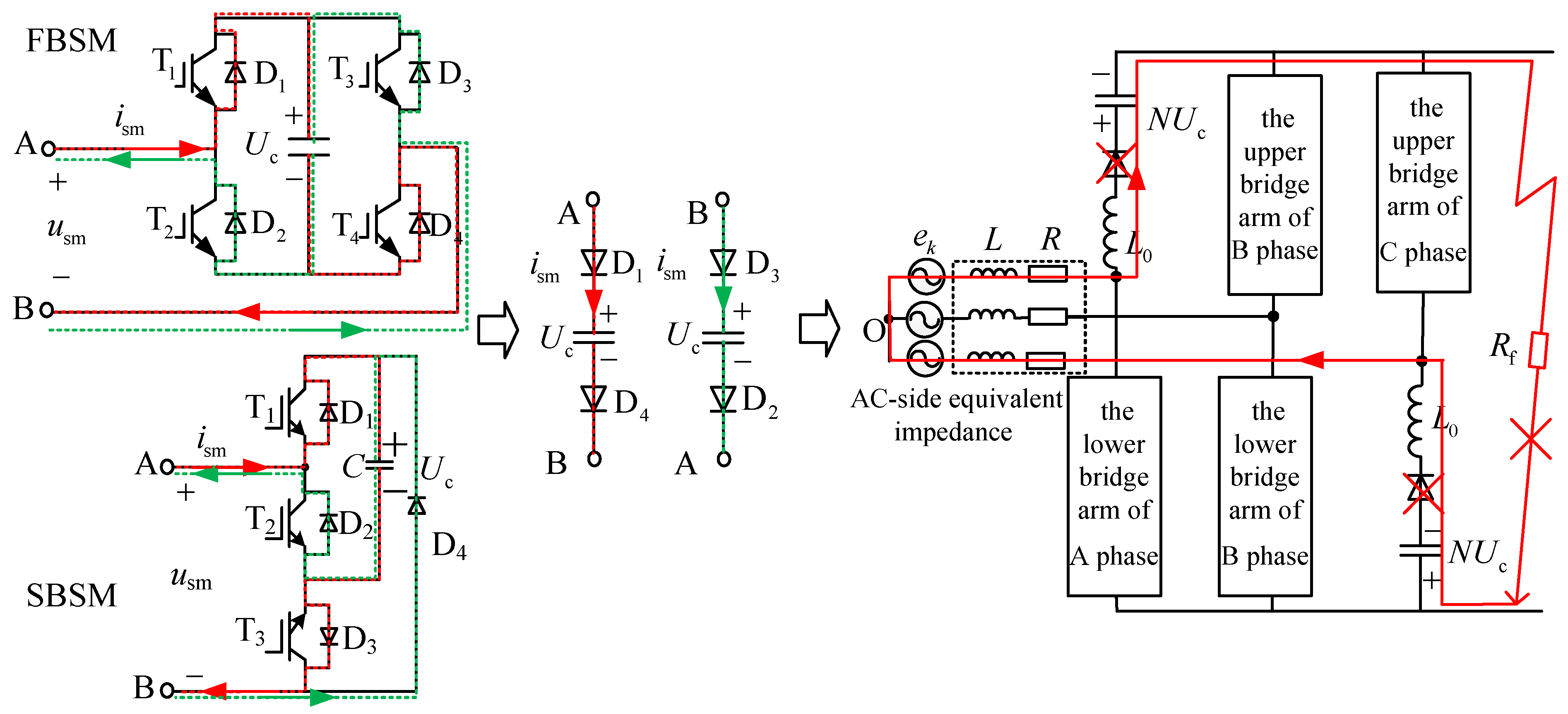
2.1. The DC Fault Isolation of MMC-HVDC Using the SM with DC Fault Self-Clearing

Topology of three-phase MMC is shown in Figure 1. The MMC with n SMs per arm is connected to the AC grid including in AC-side equivalent impedance. After the short-circuit fault happens, the SMs of the converter are stopped from triggering. With the quick decline of bridge arm reactor freewheeling current, the MMC is close to an uncontrolled state.
Figure 2 shows the uncontrolled circuit after blocking the converter when the relation of the grid voltages is ea > eb > ec. By use of the undirectional continuity of diode, capacitor is introduced into the fault path and provides reverse voltage to block fault current. The SM is equivalent to a capacitor and two diodes in series no matter which direction the current follows. Therefore, the SM with DC fault self-clearing has the ability to isolate the DC fault. When permanent fault happens, the short circuit will be blocked as long as sum of capacitor voltages of bridge arm is greater than the grid voltage. After the converter blocking, the SM capacitors don’t discharge. So the MMC has an opportunity to be put on hot standby during system shutdown.
In Figure 2, the structure of the full-bridge sub-module (FBSM) includes four insulated gate bipolar transistors (IGBTs), four antiparallel diodes and one capacitor. When the SM works, ±1 and 0 are output. Self-blocking sub-module (SBSM) has one less IGBT than FBSM, but which cannot generate −1 level when the SM works. Under normal operational conditions, T3 is always on, which is equivalent to HBSM. In fact, both FBSM and SBSM are equivalent to HBSM and do not require −1 level when the MMC-HVDC works normally. The equivalent circuits of FBSM and SBSM are the same when the MMC-HVDC are blocked. So many SM topologies similar to SBSM are proposed by scholars in order to simplify the circuit of the SM, for example CDSM, DCSM, SBSM, Hybrid SM, SDSM, SCSM, and so on. In this paper, the simplified SMs with DC fault self-clearing are referred to as ‘no-negative-level sub module’ (NNLSM).

2.2. Capacitor Voltage Divergence of MMC-HVDC Using the SM with DC Fault Self-Clearing

Since the capacitor of the SM with DC fault self-clearing cannot be charged for a long time, its voltage will be attenuated naturally. When the sum of capacitor voltages of bridge arm attenuates to less than the grid voltage, these capacitors are charged through the diode from the grid. The sum of capacitor voltages of the bridge arm will be maintained around the peak value of line voltage. Capacitance voltages of the SMs on a bridge arm actually have some differences. At this time, the current flowing into each SM on a bridge arm is equal, but the currents consumed by constant power loads in the SMs have some differences, resulting in capacitor voltage divergence phenomenon. These constant power loads are used for sub module control, protection, and state monitoring, as shown in Figure 3.
In addition to switching devices and a capacitor, a real circuit of an SM includes drive circuit boards, the sensors, bypass relay, control circuit board, and so on. The above components required by the low-voltage power supplies directly derived through the capacitor, and have the constant power characteristics. The above components can be equivalent to a constant power load in parallel with the capacitor in Figure 3. So capacitor voltage of a SM is written as follows during the blocked state:
U c i = 1 C i t 0 t 1 ( i arm i P SM i U c i ) d t + U c i 0 .
where Uci0 (i = 1, 2, 3, …, n) is the capacitor voltage of the SM before the converter is blocked, Uci is the capacitor voltage of the SM after the converter blocking, Ci is the capacitance of the SM, iarmi is the current flowing into the SM, and PSMi (i = 1, 2, 3, …, n) is power loss of the constant power load.
Suppose power losses of the constant power loads and capacitances are equal between any two SMs on an upper or lower bridge arm. When the voltage difference between the two SMs exists at the initial time, the voltage difference as time goes on is accumulated as follows:
Δ U c = e P SM C t 0 t 1 1 U c i U c j d t + Δ U c 0 , i j .
where Uci, Ucj (i, j = 1, 2, 3, …, n) are, respectively, the capacitor voltages of the two SMs after the converter blocking. ΔUc is the voltage difference between the two SMs after the converter blocking, ΔUc0 is the voltage difference between the two SMs at the initial time.
It can be seen from Equation (2) that the voltage difference between any two SMs will gradually increase as time goes on. From Equation (1), the lower capacitor voltage of the SM makes the greater loss current for constant power load characteristics. On the contrary, the higher capacitor voltage of the SM makes the smaller the loss current. Capacitor voltage divergence accelerates under the integral action.
Simulation of capacitor voltage divergence is shown in Figure 4. Due to the memory limitation of the computer, the constant power load is set relatively high to speed up the simulation process. In actual situation, the above phenomenon is completed within 30 s to 1 min. After the MMC with eight SMs on a bridge arm is blocked at 0.5 s, the capacitor voltages have been decreasing and diverging slowly due to power loss. After the sum of capacitor voltages of bridge arm decreases to peak value of line voltage around 1.2 s, capacitor voltage divergence accelerates. However, the sum of capacitor voltages of the bridge arm has being clamped around peak value of the line voltage. Since the AC breaker may be tripped for overvoltage or under voltage on some SMs, the MMC-HVDC will exit hot standby.
So when the permanent DC fault happens or the fault cannot be cleared in a short period of time, capacitor voltage divergence may happen. The SM with DC fault self-clearing has the ability to isolate the DC fault when DC fault happens, but the MMC-HVDC cannot keep hot standby for a long time, which is unfavorable to quick restarting following the clearance of DC faults.

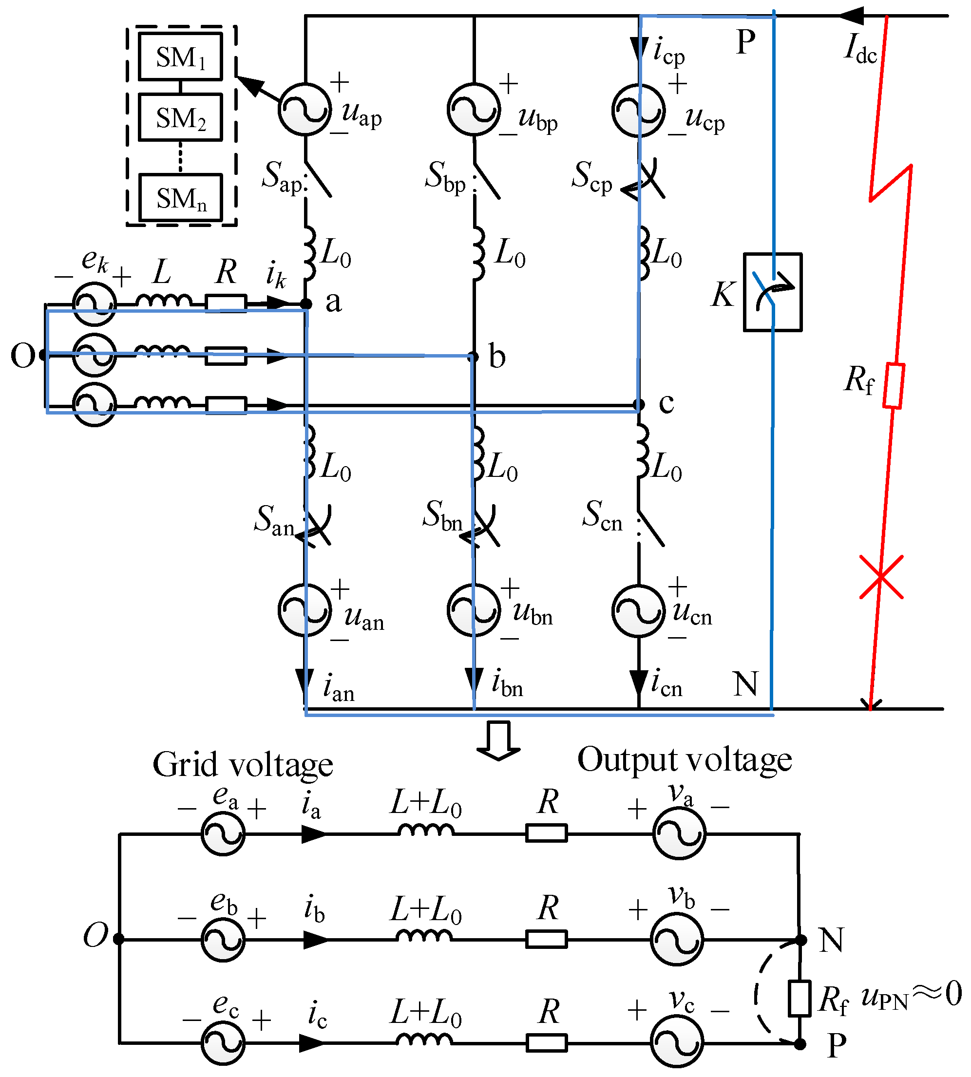
3. DC Short-Circuit Fault Ride Through Principle Based on the Cascaded Star Converter

In order to maintain and balance the capacitor voltages during the fault ride through, this paper proposes a DC short-circuit fault ride through strategy based on the cascaded star converter. The strategy is especially applicable to MMC-HVDC using the NNLSMs that cannot generate −1 level.
From Section 2, whether the SM with DC fault self-clearing works or not can determine the current flowing into the SM or off. This is equivalent to some virtual switches installed on the three-phase upper and lower bridge arms of MMC. Figure 5 shows the equivalent topology of MMC using the SM with DC fault self-clearing during the fault ride through. Skp and Skn (k = a, b, c) represent the virtual switches of the upper and lower bridge arms. Skp and Skn cannot be on and off simultaneously. As small power is used to maintain and balance the capacitor voltages of the SMs, the controlled bridge arm current is near zero, which is equivalent to control the voltage of the upper or lower bridge arm near the grid voltage.
u k n or u k p e k ,    ( k = a , b , c )
where ukn, ukp (k = a, b, c) are the output voltages of the k phase upper and lower bridge arms; ek (k = a, b, c) is the k phase grid voltage.
As the NNLSM only outputs +1 and 0 level, the output voltages of the upper and lower bridge arm only output positive voltage. In order to realize Equation (3), the switches are chosen as follows:
S k p = { 1 e k 0 0 e k > 0 , S k n = { 1 e k > 0 0 e k 0 .
where ‘1’ represents turn-on and ‘0’represents turn-off.
After the DC fault is isolated, one phase upper or lower bridge arm works and the other is off according to the polarities of grid voltages. According to the phase voltage polarities, the control cases of the virtual switches Skp and Skn are shown in Figure 6. The control cases can be divided into six sections in one cycle. When the polarity is positive, all the IGBTs of the upper bridge arm are blocked and the output voltage of the lower bridge arm is controlled against grid voltage of the phase. When the polarity is negative, all the IGBTs of lower bridge arm are blocked and the output voltage of the upper bridge arm is controlled against grid voltage of the phase.
The third section is used as an example to analyze the state of the virtual switches during the fault ride through, shown in Figure 5. At this section, the grid voltage polarities of A, B, and C phase are positive, positive, and negative, respectively. At this time, Sap, Sbp, and Scn are equivalent to turn off, and San, Sbn, and Scp are equivalent to turn on.
The mathematical model of MMC-HVDC in the third section is rewritten as follows:
{ e a + ( L + L 0 ) d i a d t + R i a + v a + u NO = 0 e b + ( L + L 0 ) d i b d t + R i b + v b + u NO = 0 e c + ( L + L 0 ) d i c d t + R i c + v c + u PN + u NO = 0  
where vk (k = a,b,c) is the output voltage of k phase bridge arm, v k = S k n u k n S k p u k p .
Put Equations (3) and (4) into Equation (5), and for the balanced three-phase AC grid, the three equations in Equation (5) are added up to obtain Equation (6) as follows:
{ i k 0 , ( k = a , b , c ) u PN u NO 0 .
For the DC bus pole-to-pole equipotential known from Equation (6), The MMC in the third section is equivalent to a cascaded star structure, as shown in Figure 5. Obviously, the short-circuit current does not exist. But the current of the DC bus is not completely zero. In order not to affect DC fault handling and ensure safety, a short-circuit branch can be also added at the outlet of the MMC. The branch switch K is turned off at the normal work of the MMC. Because the branch switch does not need to have arcing ability and its withstand current is very small, the cost is very low.
In the other sections, Equation (6) is similarly satisfied. So the MMC in six sections may be seen as a cascaded star structure under the fault ride through strategy.

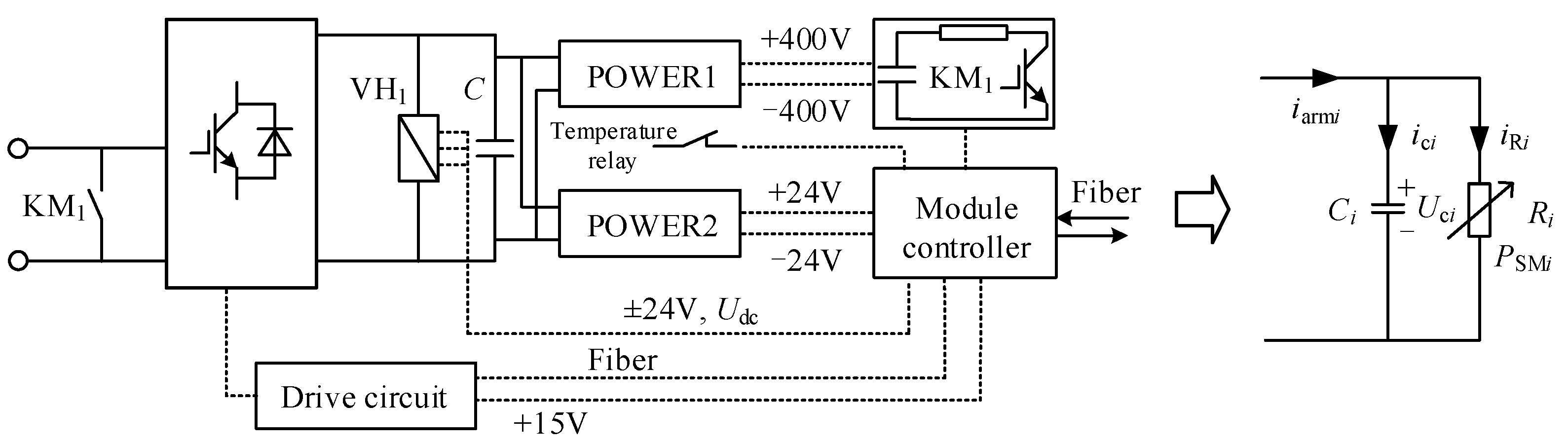
4. Implementation of DC Short-Circuit Fault Ride Through Strategy Based on the Cascaded Star Converter

The control block diagram of the proposed DC short-circuit fault ride through strategy is shown in Figure 7. The result of u ¯ ABCL minus average capacitor voltage reference ucref* goes through a proportional-integral regulator PI, and d component of the grid current reference id* is obtained for maintaining the total capacitor voltage of the working three-phase upper and lower bridge arms. u ¯ ABCL is the average capacitor voltage of the working three-phase upper and lower bridge arms. According to the polarity of grid voltages, the capacitor voltages of the SMs are chosen from the upper or lower bridge arms, and inputted to obtain u ¯ ABCL , as shown in Figure 8a. u i LP 1 ,     , u i LP n (i = A, B, C) are the capacitor voltages of the SMs on the upper bridge arms. uiLN1, …, uiLNn (i = A, B, C) are the capacitor voltages of the SMs on the lower bridge arms.
Direct current control is adopted to achieve the gird current control in Figure 7. In addition to controlling the total capacitor voltage of the working three-phase upper and lower bridge arm, the capacitor voltages of the SMs need balance. Cluster balancing control and individual balancing control are commonly adopted in the cascaded star converter. S are the switching signals used to control the switching devices of the SMs.
Cluster balancing control is used to balance the capacitor voltages between phase clusters. As is known from Figure 6, the main circuit structure changes according to the polarity of the three-phase grid voltages. The common cluster balancing control based on zero-sequence voltage or negative-sequence voltage [29,30] will change the phase angles of the modulation waves, which causes the bridge arms that cannot modulate the required voltage to withstand the grid voltage. Therefore, this paper proposes a novel cluster balancing control method in Figure 8b to slightly scale the amplitude of the modulated wave without changing the phase. u ¯ ABCL subtracts the average capacitor voltage of the working each-phase upper or lower bridge arm u ¯ AL , u ¯ BL , u ¯ CL , respectively. The results go through three proportional-integral regulators to obtain scaling factors of the modulated waves. This method results in a slight scaling of the amplitude and zero crossing positions of the modulated waves remain unchanged. The required power to maintain the capacitor voltages is small and the reassignment power required for cluster balancing control is even smaller. So the scaling does not cause the three-phase currents to grow too large.
Individual balancing control is used to balance the capacitor voltages of the SMs on one bridge arms, as shown in Figure 8c. The method is same as that of conventional three-phase cascaded star converter [31]. The average capacitor voltage of a working upper or lower bridge arm u ¯ m L , ( m = A , B , C ) subtracts the capacitor voltages of the SMs, respectively. The results go through proportional-integral regulators to finely adjust pulse widths, respectively.
After the DC fault is identified, all the SMs of MMC-HVDC using the SM with DC fault self-clearing are blocked first to clear the fault current quickly. Then the MMC-HVDC is switched to fault ride through mode. All the capacitor voltages during the fault ride through are maintained and balanced. And the MMC-HVDC has being connected to the grid and keeps hot standby. After the fault is cleared, the system is switched to the normal operational mode and the power transmission is recovered quickly.

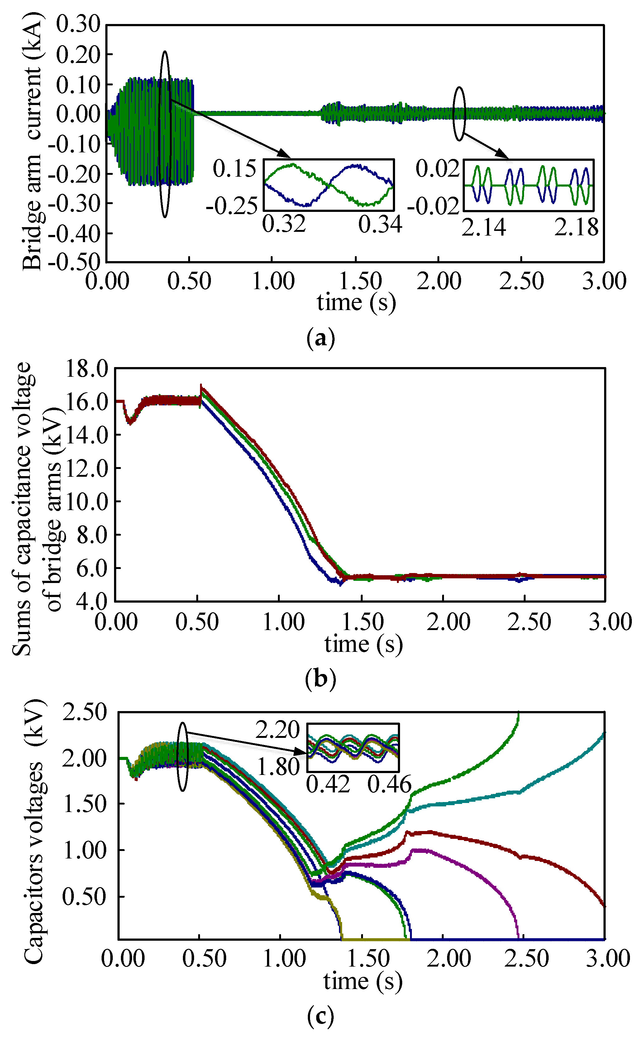
5. Simulation Verification

To verify the proposed DC short-circuit fault ride through strategy of MMC-HVDC based on the cascaded star converter, 21-level unilateral MMC-HVDC is built in PSCAD/EMTDC. Its SM topology adopts SBSM. The system parameters are shown in Table 1. The capacitor voltage of the SM is higher than the practical, because fewer SMs are used in the simulation model compared with that in the practical application in order to accelerate simulation.
The simulation results are shown in Figure 9. A line-to-line short-circuit fault between P point and N point of DC bus is occurring at t = 2.401 s. After 2 ms, all the IGBTs of the MMC-HVDC are turned off for too large a current. The normal operational mode is closed. The DC short-circuit fault ride through strategy runs at t = 2.408 s. The interval time is in order to ensure the clearance of fault current. The DC fault is relieved at 4 s, and the system is switched to the normal operational mode. The MMC-HVDC works in the constant DC voltage and active power mode under the normal operational mode.
After the line-to-line short-circuit fault happens, the DC current and the grid currents increase quickly, and the DC voltage is reduced to around zero in a short span of time. After all the IGBTs of the MMC-HVDC are turned off at t = 2.403 s, the DC fault current is reduced to zero quickly. Then after the DC fault ride through strategy runs at 2.408 s, the grid currents, the DC current and DC voltage still maintain near zero, which is shown in Figure 9a. This shows that the strategy does not cause short-circuit current. After the DC fault happens, the power transmission is cut off, as shown in Figure 9b. Because a little part of the power is absorbed to maintain and balance the capacitors voltages of the SMs, the active power fluctuates slightly around zero during the DC fault ride through. After the fault is relieved at 4 s, the transmission power of MMC-HVDC is recovered rapidly. The bridge arm current of A phase is on alternatively, following selection signal of the upper and lower bridge arm shown in Figure 9c. This phenomenon proves the existence of virtual switches. In Figure 9d, the capacitor voltages of the SMs balance and do not diverge during DC fault ride through. Due to the proposed cluster balancing control method, it takes a relatively short time to balance the capacitor voltages between phase clusters. Table 2 gives a detailed comparison with other strategies.

6. Conclusions

The SM with DC fault self-clearing can achieve DC short-circuit fault isolation. But when it may take a long time for the system to relieve the DC fault, the capacitor voltage divergence will happen on the SMs, which causes the MMC-HVDC not to keep hot standby for a long time. In this paper, it is proved that the constant power load in the SM leads to the capacitor voltage divergence. Therefore, this paper proposes a DC short-circuit fault ride through strategy of MMC-HVDC based on the cascaded star converter. The three working upper or lower bridge arms are chosen according to the grid voltage polarities, and the MMC may be seen as a cascaded star converter. Through the strategy similar to the cascaded star converter, the capacitor voltages are maintained and balanced during fault ride through. The proposed cluster balancing control by scaling the amplitude of the modulated wave does not affect the modulated wave polarity, and can balance the capacitor voltages between phase clusters without the growing three-phase currents. The effectiveness of the proposed DC short-circuit fault ride through strategy is demonstrated on simulation model in PSCAD/EMTDC.
The proposed DC short-circuit fault ride through strategy enjoys the following advantages:
(a)
The short-circuit current does not exist during DC short-circuit fault ride through;
(b)
The converter is controllable during fault ride through, which avoids the divergence of the capacitor voltages;
(c)
The AC breaker will not be tripped. After the fault is cleared, the power transmission is recovered quickly; and
(d)
The strategy can be applied to more MMC-HVDC topologies including in the topologies using the SMs with DC fault self-clearing but not generating −1 level.

Author Contributions

Y.W. and B.Y. design the research; H.Z. and H.L. collected and compiled the data and literature; Y.W. and H.Y. finished the simulation and calculation; Y.W. and B.Y. analyzed the results and put forward the policies. All authors read and approved the final manuscript.

Funding

This research was funded by the Fundamental Research Funds for the Central Universities (2017XKQY029).

Conflicts of Interest

The authors declare no conflict of interest.

References

  1. Flourentzou, N.; Agelidis, V.G.; Demetriades, G.D. VSC-based HVDC power transmission systems: An overview. IEEE Trans. Power Electron. 2009, 24, 592–602. [Google Scholar] [CrossRef]
  2. Wang, S.; Tang, G.; He, Z. Comprehensive evaluation of VSC-HVDC transmission based on improved analytic hierarchy process. In Proceedings of the 2008 Third International Conference on Electric Utility Deregulation and Restructuring and Power Technologies, Nanjing, China, 6–9 April 2008. [Google Scholar]
  3. Li, R.; Fletcher, J.E.; Xu, L.; Holliday, D.; Williams, B.W. A hybrid modular multilevel converter with novel three-level cells for DC fault blocking capability. IEEE Trans. Power Deliv. 2015, 30, 2017–2026. [Google Scholar] [CrossRef]
  4. Lesnicar, A.; Marquardt, R. An innovative modular multilevel converter topology suitable for a wide power range. In Proceedings of the 2003 IEEE Bologna Power Tech Conference, Bologna, Italy, 23–26 June 2003. [Google Scholar]
  5. Song, Q.; Liu, W.; Li, X.; Rao, H.; Xu, S.; Li, L. A steady-state analysis method for a modular multilevel converter. IEEE Trans. Power Electron. 2013, 28, 3702–3713. [Google Scholar] [CrossRef]
  6. Saeedifard, M.; Iravani, R. Dynamic performance of modular multilevel back-to-back HVDC system. IEEE Trans. Power Deliv. 2011, 25, 2903–2912. [Google Scholar] [CrossRef]
  7. Meyer, J.M.; Rufer, A. A DC hybrid circuit breaker with ultra-fast contact opening and integrated gate-commutated thyristors (IGCTs). IEEE Trans. Power Deliv. 2006, 21, 646–651. [Google Scholar] [CrossRef]
  8. Franck, C.M. HVDC circuit breakers: A review identifying future research needs. IEEE Trans. Power Deliv. 2011, 26, 998–1007. [Google Scholar] [CrossRef]
  9. Nakao, H.; Nakagoshi, Y.; Hatano, M.; Koshizuka, T.; Nishiwaki, S.; Kobayashi, A.; Murao, T.; Yanabu, S. DC current interruption in HVDC SF/sub6/gas MRTB by means of self-excited oscillation superimposition. IEEE Trans. Power Deliv. 2002, 16, 687–693. [Google Scholar] [CrossRef]
  10. Candelaria, J.; Park, J.D. VSC-HVDC system protection: A review of current methods. In Proceedings of the 2011 IEEE/PES Power Systems Conference and Exposition, Phoenix, AZ, USA, 20–23 March 2011. [Google Scholar]
  11. Schmitt, D.; Wang, Y.; Weyh, T.; Marquardt, R. DC-side fault current management in extended multiterminal-HVDC-grids. In Proceedings of the International Multi-Conference on Systems, Sygnals & Devices, Chemnitz, Germany, 20–23 March 2012. [Google Scholar]
  12. Debnath, S.; Qin, J.; Bahrani, B.; Saeedifard, M.; Barbosa, P. Operation, control, and applications of the modular multilevel converter: A review. IEEE Trans. Power Electron. 2014, 30, 37–53. [Google Scholar] [CrossRef]
  13. Tang, G.; Xu, Z.; Zhou, Y. Impacts of three MMC-HVDC configurations on AC system stability under DC line faults. IEEE Trans. Power Syst. 2014, 29, 3030–3040. [Google Scholar] [CrossRef]
  14. Yang, J.; Fletcher, J.E.; O’Reilly, J. Short-circuit and ground fault analyses and location in VSC-based DC network cables. IEEE Trans. Ind. Electron. 2014, 29, 3030–3040. [Google Scholar] [CrossRef]
  15. Elserougi, A.A.; Abdel-Khalik, A.S.; Massoud, A.M.; Ahmed, S. A new protection scheme for HVDC converters against DC-side faults with current suppression capability. IEEE Trans. Power Deliv. 2014, 29, 1569–1577. [Google Scholar] [CrossRef]
  16. Li, X.; Song, Q.; Liu, W.; Rao, H.; Xu, S.; Li, L. Protection of nonpermanent faults on DC overhead lines in MMC-based HVDC systems. IEEE Trans. Power Deliv. 2013, 28, 483–490. [Google Scholar] [CrossRef]
  17. Marquardt, R. Modular Multilevel Converter: An universal concept for HVDC-Networks and extended DC-Bus-applications. In Proceedings of the 2010 International Power Electronics Conference—ECCE Asia, Sapporo, Japan, 21–24 June 2010. [Google Scholar]
  18. Soto-Sanchez, D.; Green, T.C. Control of a modular multilevel converter-based HVDC transmission system. In Proceedings of the 2011 14th European Conference on Power Electronics and Applications, Birmingham, UK, 30 August–1 September 2011. [Google Scholar]
  19. Marquardt, R. Modular Multilevel Converter topologies with DC-Short circuit current limitation. In Proceedings of the 8th International Conference on Power Electronics—ECCE Asia, Jeju, Korea, 30 May–3 June 2011. [Google Scholar]
  20. Zhang, J.; Zhao, C.; Sun, H.; Huang, X.; Yi, L.; Peng, Q. Improved topology of modular multilevel converter and application. Trans. China Electrotech. Soc. 2014, 29, 173–179. [Google Scholar]
  21. Zeng, R.; Xu, L.; Yao, L. An improved modular multilevel converter with DC fault blocking capability. In Proceedings of the 2014 IEEE PES General Meeting | Conference & Exposition, National Harbor, MD, USA, 27–31 July 2014. [Google Scholar]
  22. Wang, X.; Lin, W.; Wen, J.; Cheng, S. A new topology of sub-modules with DC fault current blocking capability and a new type of hybrid MMC converter. Proc. CSEE 2014, 34, 5171–5179. [Google Scholar]
  23. Li, X.; Liu, W.; Song, Q.; Rao, H.; Xu, S. An enhanced MMC topology with DC fault ride-through capability. In Proceedings of the IECON 2013—39th Annual Conference of the IEEE Industrial Electronics Society, Vienna, Austria, 10–13 November 2013. [Google Scholar]
  24. Elserougi, A.A.; Massoud, A.M.; Ahmed, S. A switched-capacitor submodule for modular multilevel HVDC converters with DC-fault blocking capability and a reduced number of sensors. IEEE Trans. Power Deliv. 2016, 31, 313–322. [Google Scholar] [CrossRef]
  25. Oliveira, R.; Yazdani, A. A modular multilevel converter with DC fault handling capability and enhanced efficiency for HVDC system applications. IEEE Trans. Power Electron. 2017, 32, 11–22. [Google Scholar] [CrossRef]
  26. Luo, Y.; Li, Y.; Li, Z.; Wang, P.; Chu, Z.; Xu, L.; Zhao, C. DC short-circuit fault ride-through control strategy of full-bridge MMC-HVDC systems. Proc. CSEE 2016, 36. [Google Scholar] [CrossRef]
  27. Adam, G.P.; Davidson, I.E. Robust and generic control of full-bridge modular multilevel converter high-voltage DC transmission systems. EEE Trans. Power Deliv. 2015, 30, 2468–2476. [Google Scholar] [CrossRef]
  28. Cui, S.; Sul, S.K. A comprehensive DC short-circuit fault ride through strategy of hybrid modular multilevel converters (MMCs) for overhead line transmission. IEEE Trans. Power Electron. 2016, 31, 7780–7796. [Google Scholar] [CrossRef]
  29. Akagi, H.; Inoue, S.; Yoshii, T. Control and performance of a transformerless cascade PWM STATCOM with star configuration. IEEE Trans. Ind. Appl. 2007, 43, 1041–1049. [Google Scholar] [CrossRef]
  30. Song, Q.; Liu, W. Control of a cascade STATCOM with star configuration under unbalanced conditions. IEEE Trans. Power Electron. 2009, 24, 45–57. [Google Scholar] [CrossRef]
  31. Zhao, T.; Wang, G.; Bhattacharya, S. Voltage and power balance control for a cascaded h-bridge converter-based solid-state transformer. IEEE Trans. Power Electron. 2013, 28, 1523–1532. [Google Scholar] [CrossRef]
Figure 1. Topology of three-phase modular multilevel converter (MMC).
Energies 11 02079 g001
Figure 2. The uncontrolled circuit after blocking the converter.
Energies 11 02079 g002
Figure 3. Real circuit topology of sub module (SM).
Energies 11 02079 g003
Figure 4. The waveform of capacitor voltage divergence after the converter is blocked. (a) Bridge arm current; (b) sum of capacitor voltages of bridge arm, and (c) capacitor voltages.
Energies 11 02079 g004
Figure 5. The equivalent circuit of MMC in the third section during the fault ride through.
Energies 11 02079 g005
Figure 6. The control method of the virtual director switches Skp and Skn.
Energies 11 02079 g006
Figure 7. The control block diagram of the proposed DC short-circuit fault ride through strategy.
Energies 11 02079 g007
Figure 8. The calculation and control block diagram of the capacitor voltage. (a) The calculation block diagram of the average capacitor voltage of the working three-phase upper and lower bridge arms; (b) the proposed cluster balancing control method, and (c) individual balancing control method of m phase.
Energies 11 02079 g008
Figure 9. The simulation results of the MMC-HVDC: (a) DC voltage and current, grid currents; (b) active and reactive power; (c) current and a single SM capacitor voltage of A phase upper bridge arm, and (d) the capacitor voltages of the SMs and the sums of the capacitor voltages of six bridge arms.
Energies 11 02079 g009aEnergies 11 02079 g009b
Table 1. The system parameters of the modular multilevel converter based high voltage direct current (MMC-HVDC).
DescriptionSymbolValue
Grid voltage Us230 kV
AC-side equivalent inductanceL0.05 H
Fundamental frequencyfb50 Hz
Rated active powerP400 MW
DC voltage Udc±200 kV
No. of SMs(per arm)N20
Capacitor voltage Uc20 kV
Capacitor valueC5000 μF
Bridge arm inductanceL00.05 H
Switching frequencyfsw200 Hz
Short-circuit resistanceRf0.01 Ω
Table 2. Comparison of three strategies.
ParameterConventional Blocking ProtectionStrategy of [26]Fault Ride Though Protection
TemporaryPermanentTemporaryPermanentTemporaryPermanent
Fault clear timeshortshortlonglongshortshort
Fault ride through capabilityyesnoyesyesyesyes
Recovery timeshortlongshortshortshortshort
Condition of MMCuncontrolleduncontrolledcontrolledcontrolledcontrolledcontrolled
IGBTs of single bridge arm4n4n3n

