Control Scheme and Power Electronics Architecture for a Wirelessly Distributed and Enabled Battery Energy Storage System


Department of Electrical and Computer Engineering, College of Engineering, The University of Alabama, Tuscaloosa, AL 35487, USA
*
Author to whom correspondence should be addressed.
Energies 2018, 11(7), 1887; https://doi.org/10.3390/en11071887
Submission received: 4 June 2018
/
Revised: 16 July 2018
/
Accepted: 16 July 2018
/
Published: 19 July 2018
Abstract
:This paper presents and evaluates a control scheme and a power electronics architecture for a Wirelessly Enabled and Distributed Battery Energy Storage (WEDES) system. It includes several independent battery modules (WEDES-MX modules) that transfer both power and information wirelessly to an On-Board Unit (OBU). Using wirelessly communicated State-Of-Charge (SOC) information from the WEDES-MX modules, the OBU part of the WEDES controller generates control commands and send them back to the WEDES-MX modules in order to control the amount of power/energy drawn from each WEDES-MX module and achieve SOC balancing. The presented controller also allows the WEDES system to maintain operation with a regulated bus voltage even if one or more WEDES-MX modules are removed or fail and under both balanced and unbalanced SOC conditions. The WEDES system with the presented WEDES controller when utilized in Electric Vehicle (EV) application, can allow for fast and safe exchange/swapping of WEDES-MX modules at an exchange station, home, or work and therefore potentially eliminating the range (mileage) anxiety issue that is associated with EVs’ range and the needed recharging time. The main objective of this paper is to present and evaluate the WEDES discharging controller for the WEDES system and present preliminary proof-of-concept scaled-down experimental prototype results.
1. Introduction
The limited driving range and the needed recharging time of the lithium-ion (Li-Ion) battery pack is one of the major/top reasons/barriers slowing down the adoption of electric vehicles (EVs) [1,2,3,4,5,6,7,8]. This is as a result of what is referred to by “Range Anxiety” [1,3,4,5]. The uncertainty and worry about if the battery of an EV has sufficient energy to reach a destination (especially for long range drives), thinking about when there is a need to recharge the battery, and/or how long is the time needed to recharge an EV battery cause anxiety. This limits the potential for EV to mostly or completely replace the need to have another gasoline or fossil fuel based vehicles in households and limits the adoption increase of EVs in commercial applications. Several methods have been discussed and/or being either developed or considered to alleviate this issue. Some of the most common ones are:
- (1)
- Increasing the capacity of the Li-Ion battery pack. This has the following drawbacks: (a) increase in the weight of the battery and decrease in available space in the EV which impacts the efficiency of the EV (unless newer high density batteries are developed); (b) increase in the needed recharging time; (c) there is still a need to wait for the EV to charge which requires longer time than refueling a gasoline or fossil fuel based vehicle within a few minutes (unless very fast chargers are continued to be developed and used as discussed below); (d) conventional battery packs integrated with EVs cannot be swapped and shared with other EVs when needed; and (e) larger battery means higher amount of energy which means higher risk of injury when there is catastrophic battery failure and fire.
- (2)
- Develop faster high-power chargers [1,2,3,9,10]. Faster chargers reduce the time needed to recharge the battery of an EV. However, there are several drawbacks and challenges associated with this option such as: (a) it is well known and documented that the faster a Li-Ion battery is charged, the smaller the number of available stored charges is and the faster capacity fading will occur (the faster the battery is charged, the faster its state-of-health will degrade and the shorter its lifetime is expected to be) [11,12,13,14]; (b) developing faster chargers requires higher power capability which requires larger investments in infrastructure that result in increased initial and lifetime costs; and (c) it is not practical to assume that high-power faster chargers can be available in every location the EV will travel to. It does not seem, as of the date of this paper, that it is practical to assume that an emergency fast charger can be brought to an EV with depleted battery while in the case of a gasoline or fossil fuel based vehicle it can quickly be refueled from another vehicle or a container that includes fossil fuel (gasoline). Note that fast charging is realizable for up to about ≈70% SOC (with Constant Current Charging Mode, CCCM) and therefore about third or more of the battery usable capacity would need to be charged at slow rate (with Constant Voltage Charging Mode, CVCM). With extreme charging, the number is lower than 70% SOC, depending on the charging rate.
- (3)
- Adopt battery swapping concept. While battery swapping concept is about a century old, there have been increased consideration of the concept and related developments [4,5,15,16]. The drawback of existing battery swapping concepts are such as: (a) the weight of the battery necessitate specialized equipment and installation methods to realize swapping which needs to be available/accessible in many locations; (b) the involved electrical and mechanical connections require trained personnel in addition to specialized equipment to perform the swapping; (c) there might be safety and reliability risks each time the battery is swapped if not done appropriately/correctly; and (d) swapping a battery with large size and heavy weight might require longer time than refueling a vehicle with gasoline. The requirements to deploy swapping locations’ infrastructure and trained personnel (especially when this needs to happen in high number of locations like gas stations) yields significant cost increase, which makes it difficult to sustain a related business. If these drawbacks can be eliminated, battery swapping could be one of the best solutions for range anxiety problem and limited driving range.
- (4)
- Dynamic Wireless Power Charging (DWPC) [7,8,17] is another potential concept that has been reconsidered especially in the recent decade. Using DWPC, the vehicle is wirelessly charged while moving from Wireless Power Transfer (WPT) system’s coils that are embedded in the street/ground. While this concept can potentially be part of the solution to range anxiety in the future, it faces two challenges: (a) Required high infrastructure cost and (b) DWPC cannot be practically expected to be available in all streets/locations.
Wireless Power Transfer (WPT) systems are increasingly being adopted or considered for power delivery in several applications, especially those which require battery charging [1,7,8,18,19,20]. This is due to several advantages that WPT power delivery can provide, including convenience and safety. It is shown in the literature that for EV charging applications, >85% total wireless power charging system efficiency can be achieved [17,18,19,20].
This paper presents power electronics architecture and a controller for a battery system that utilizes three different technologies: Wireless power, wireless communication, and a new wirelessly distributed energy sharing and regulation based control scheme. What is presented in this paper is a control method for a Wirelessly Enabled and Distributed battery Energy Storage (WEDES) system concept. In a WEDES system, there are several independent battery modules (WEDES-MX modules) that transfer both power and information wirelessly to an On-Board Unit (OBU). As apparent from the next sections, the WEDES system when utilized in Electric Vehicle (EV) application, can allow for fast and safe exchange/swapping of WEDES-MX modules at an exchange station, home, or work and therefore potentially eliminating the range (mileage) anxiety issue that is associated with EVs’ range and needed recharging time. Due to the characteristics of the wirelessly distributed control architecture and the WEDES system, the exchange is safe because each WEDES-MX module is completely enclosed with no wired/conductive electrical connection to the outside. The exchange is fast because the weight of each individual WEDES-MX module is a portion of the weight of the total system and can potentially be handled by a healthy person (adult) with average strength and because exchanging a WEDES-MX module can be as simple as sliding it out of a slot and sliding a new charged one into the slot. The presented control and power electronic system architecture make these characteristics and advantages of the WEDES system possible. Moreover, the presented wirelessly distributed controller allows the WEDES system to achieve and maintain SOC balancing as the WEDES-MX modules are exchanged/swapped and if they are not matched.
The next section introduces the basic architecture of the WEDES system and discusses the requirements for such system to be practical. Section 3 presents the wirelessly distributed WEDES controller with an example implementation for the WEDES system. Section 4 presents proof-of-concept (POC) low-power scaled-down prototype results for validation and evaluation for the presented wirelessly distributed WEDES controller. The conclusion is given in Section 6.
2. Principle of the WEDES System Architecture and Related Implementation Requirements
Before presenting the wirelessly distributed WEDES controller in the next section, this section discusses the WEDES system architecture. Figure 1 shows an illustration of a general diagram for an EV with a conventional battery pack and electric drive system (the location of the battery is just for illustration purposes while keeping in mind that the actual location of the battery might be different in practical EVs). The battery pack supplies a nonregulated bus voltage to the rest of the system. Depending on the type of the electric drive, DC or AC, the bus voltage from the battery is regulated to a DC voltage or AC voltage. In this case, the battery pack is usually large, heavy, and not easily swappable. The battery pack would need to be charged while in the EV, either through a wired/conductive connection or wirelessly (e.g., inductive). The drawbacks of this method are discussed in the previous section (Section 1).
Consider the case when a conventional battery pack is divided into N battery modules as illustrated in Figure 2a (which is usually the case inside a state-of-the-art battery pack). However, consider that in this case, unlike in conventional battery packs, each of these modules is inside an enclosure with no wired/conductive connection to the outside as illustrated in Figure 2b. This is the first step which yields to what is referred to in this paper by the Wirelessly Enabled and Distributed Battery Energy Storage (WEDES) system with several independent battery modules (WEDES-MX modules).
Each WEDES-MX module includes battery cells in addition to dedicated electronics and wirelessly exchanges power, information, and control commands with an On-Board Unit (OBU) as illustrated in Figure 2 and Figure 3. The OBU combines the power from multiple WEDES-MX modules and deliver a regulated voltage/current/power to the rest of the system.
Figure 2b shows an illustration of how a WEDES-MX module conceptual design might look like. It is a box container with a handle (for carrying/handling) that communicates with the OBU through an inductive wireless power transfer and a low-power short-range communications (LP-SRC). The OBU includes host slots, as illustrated in Figure 2c, which accept the insertion of WEDES-MX modules (for example using tracks for sliding mechanism as illustrated in Figure 2b). As a result, the WEDES-MX modules are easily removable and swappable. They can potentially be replaced with charged modules within approximately the same time it takes to fill up a tank of a fossil fuel gasoline vehicle and within a shorter time that it takes to charge a conventional battery pack integrated in an EV (by using most available chargers nowadays). The uncharged WEDES-MX modules can be charged outside the EV using a charging station with host slots.
In order for the WEDES system concept to function and be usable and advantageous, the system and its controller (the WEDES controller) should have the following characteristics:
- (1)
- The WEDES system and controller should be able to control the SOC of each WEDES-MX module such that the energy drawn from each module is based on its SOC value and such that SOC balancing is achieved even when asymmetrically charged modules are used/inserted.
- (2)
- The WEDES-MX modules should not need to communicate with each other and only need to communicate with the OBU, which is the assumption in this paper. Otherwise the WEDES system becomes impractical and WEDES-MX modules cannot be easily exchanged and swapped between multiple EVs.
- (3)
- It is desired that the OBU is able to have a controller that allows it to operate with multiple WEDES-MX modules (N modules) when they are all inserted in the receiving host and when one or some of the WEDES-MX modules are missing from the host (up to a limited M number of missing modules based on a given design). For example, for an OBU that can accept N = 9 WEDES-MX modules, the system might be designed to be able to still operate with N − M = 9 − 3 = 6 WEDES-MX modules. This is desired in order for the system to operate either when one or more WEDES-MX modules become fully discharged or faulty (turned-off because a fault is detected or for other safety/protection reason) or when one or more WEDES-MX modules are being swapped or exchanged.
- (4)
- The weight of each WEDES-MX module can be no higher than what a healthy person (adult) with average strength can lift off ground for a short time during exchange/swapping.
It should be noted that under the assumption that conventional existing gas (fossil fuel) stations have WEDES-MX modules in stock and that users/drivers can swap WEDES-MX at all or most gas stations that exist today, the total battery system’s capacity might not need to be as large as it is in today’s conventional battery packs for EVs. This is because of swapping availability and relative easiness.
While the earlier discussion in this paper and the rest of this paper assumes that the complete battery pack is divided into N WEDES-MX modules in the WEDES system, another option is to have part of the battery pack kept fixed and part is transformed to WEDES-MX modules. For example, 15 kWh part of a 35 kWh battery pack can be replaced by five swappable WEDES-MX modules and 20 kWh part is kept fixed/non-swappable (as if it is the sixth WEDES-MX module in terms of how it is controlled).
The next question this paper addresses is: what is the control architecture and possible power electronic implementation that would make the WEDES system have most of the characteristics described earlier? The next section presents the proposed operation concept and proposed wirelessly distributed controller, which has the potential to make the WEDES system realizable and practical.
3. The WEDES Controller and Its Operation Principle
Figure 4 shows an illustration for a more detailed (than Figure 3) block diagram of the WEDES system. Each WEDES-MX module consists of the following main parts:
- (1)
- Battery cells that are connected in series and/or in parallel combination. This forms a battery bank which determines the voltage, current, power, and energy capabilities of each WEDEX-MX module.
- (2)
- A DC-DC power converter (e.g., boost converter in the design example of this paper and its experiment) with closed-loop control. The input to this converter is the battery bank in (1) and the output is a regulated DC voltage (VMX1 through VMXN) that is adjusted to realize SOC balancing control and bus voltage regulation as described later in this section. This output is connected to an inverter power stage.
- (3)
- An open-loop DC-AC inverter stage with fixed duty cycle such as a half-bridge (or full-bridge) with 50% duty-cycle. The input to this inverter is the DC voltage from the DC-DC power converter in (2) and the output is an AC voltage/current that is applied to the Inductive Wireless Power (I-WPT) transmitter (Tx) for inductively transmitting wireless power to the OBU.
Note that (2) and (3) can be realized using single-stage power inverter topology if desired instead of a two-stage topology that consists of a DC-DC stage that is followed by a DC-AC stage.
The OBU mainly consists of the I-WPT receiver (Rx) coils followed by power stage for AC-DC rectification/conversion or AC-AC conversion. While there are several ways to generate a combined output as illustrated in Figure 4, this paper focuses on the following configuration: Each Rx coil is connected to a diode full-bridge rectifier and the DC outputs (Vo1 through VoN) of the rectifiers are connected in series (Vbus = Vo1 + Vo2 + … + VoN). Figure 5 shows a simplified illustration of a schematics of such possible implementation.
Figure 6 shows a simplified diagram for the presented wirelessly distributed WEDES controller. The black/dark parts of Figure 6 indicate that they are realized as a part of the OBU, while the blue/light parts indicate that they are realized as a part of the WEDES-MX modules. The WEDES controller consists of two main control loops, the bus voltage control loop and the SOC (State-Of-Charge) control loop. The bus voltage control loop regulates the total output bus voltage Vbus of the OBU which supplies power to a load while using the SOC multiplier values αMX1 through αMXN generated by the SOC control loop in order to archive SOC balancing between N WEDES-MX modules. The WEDES controller archives SOC balancing by mismatching the values of the output voltages VMX1 through VMXN of the DC-DC power converter stages in each of the N WEDES-MX modules (refer to Figure 4 through Figure 6).
The first stage of the bus voltage control loop (upper left part in Figure 6) uses a closed-loop compensator with a transfer function Gv-bus in order to compare the desired value of the bus voltage Vbus-ref to the measured value of Vbus and generate the value VMX-total. The value of VMX-total as given by Equation (1) represents the needed sum/total value of VMX1 through VMXN in order to achieve the desired Vbus value, even when there is a power loss (and therefore efficiency) mismatch between the power paths and wireless power links of the different modules (which is an important part of the presented controller). The VMX-total value is then multiplied by the weighting factors λDC1 through λDCN as given by Equation (2) in order to generate the reference values VMX1-DC-ref through VMXN-DC-ref as given by Equation (3), where r = 1, 2, …, N and N is the number of active WEDES-MX modules. In Equations (2) and (3), αMX1 through αMXN are the SOC multipliers that are generated by the SOC loop and δMX1 through δMXN are enable/disable values each with either “1” value or “0” value. When an rth WEDES-MX module is detected by the WEDES-MX controller in the OBU, its corresponding δMXr value is set to “1” in order to account for it in the controller’s operation, otherwise it is set to “0.” This detection is performed by checking if the voltage across the capacitor (COBU1, COBU2, or COBU3 in Figure 5) of AC-DC or bridge rectifier is above certain value Ven or not (e.g., Ven > 1 V):
where , and .
Note that if SOC multiplier αMX1 through αMXN are equal, the values of VMX1-DC-ref through VMXN-DC-ref are also equal. This condition occurs when the SOC of all WEDES-MX modules are equal and the design of all WEDES-MX modules and their WPT links to the OBU are symmetric. The OBU wirelessly transmits VMX1-DC-ref through VMXN-DC-ref via the LP-SRC link to the WEDES-MX modules (one value for each module). The rth VMXr-DC-ref value received by the rth WEDES-MX module serves as the voltage reference value for the rth output voltage VMXr of the rth DC-DC power converter stage in the rth WEDES-MX module (refer to Figure 4 through Figure 6). The closed-loop compensator with transfer function GvMX regulates the values of VMX1 through VMXN by comparing them to the values of VMX1-DC-ref through VMXN-DC-ref.
The SOC control loop generates the SOC multiplier values αMX1 through αMXN by comparing the SOC values SOCMX1 through SOCMXN (which are sent wirelessly by the WEDES-MX modules to the OBU via the LP-SRC link) to a reference value SOCMX-v-ref as given by Equation (4). This is done by using closed-loop compensators with transfer function GvSOC in order to generate the SOC multiplier values αMX1 through αMXN used by the bus voltage control loop which is describe earlier and as shown in Equations (2) and (3):
where = N when all modules are inserted and active.
The operation of the WEDES controller described above based on Figure 6 guarantees that (1) the bus voltage is always regulated at the desired value; (2) the WEDES-MX modules are forced to reach a balanced SOC condition if they were initially unbalanced; and (3) the SOC balance between the WEDES-MX modules is maintained after achieving the SOC balance.
The main two sets of control parameters that are transmitted wirelessly between the OBU and the WEDES-MX modules are the SOC set of values, SOCMX1 through SOCMXN, which are transmitted from the WEDES-MX modules to the OBU and the set of voltage reference values, VMX1-DC-ref through VMXN-DC-ref, which are transmitted from the OBU to the WEDES-MX modules.
It might be important to emphasize the need for this part of the controller that generates VMX-total from Vbus-ref and Vbus (upper left part in Figure 6). This part of the controller is one of the most unique parts to the WEDES controller (in addition to other unique aspects such as the wirelessly distributed control scheme with SOC balancing) and it is needed especially because of the nature of the WEDES system architecture and the existence of multiple wireless power links which can have mismatches. If the outputs of the DC-DC boost converters are directly connected in series to form the bus voltage Vbus, then simply VMX-total = Vbus. However, since in the WEDES system this is not the case, and because there is the DC-AC stage, WPT link stage, and AC-DC stage that have less than 100% efficiency, this will result in needing VMX-total > Vbus, which requires its own closed-loop control to be determined. The value of VMX-total depends on the conversion ratios and losses of these stages between input and the output at the OBU side.
4. Experimental Prototype Results
This section presents results obtained from a low-power scaled-down proof-of-concept (POC) prototype. The purpose of this POC prototype is to validate and evaluate the presented WEDES controller and system. The operation principle of the presented wirelessly distributed controller should not be different under different power/energy levels.
The POC consists of three WEDES-MX modules and its implementation follows the description given throughout this paper especially in Section 3, Figure 5 and Figure 6. Five 2.6 Ah 18650-size cylindrical lithium-ion battery cells each with a nominal voltage of 3.7 V [21] that are connected in series (total nominal voltage of 18.5 V) are used in each WEDES-MX modules (at the input of each DC-DC boost power converter). The DC-DC boost converter is with a switching frequency of 150 kHz and a power inductor of 4.7 µH. The switching frequency of the DC-AC bridge stage for WPT is 50 kHz. Commercially available WPT coils [22] with magnetic layer from Wurth Electronics Inc. (Headquarters in Niedernhall and Waldenburg, Germany; manufacturer part number 760308100110) are used at the TX side (WEDES-MX module output) and Rx side (OBU inputs). Some of the main nominal specifications of this WPT coil include 24 µH inductance, 70 mΩ DC resistance, and 10 A saturation current (please refer to datasheet [22] for additional details on the design of this WPT coil). A full bridge rectifier diode at the output of each WPT Rx coil in the OBU is used and the outputs of all bridge rectifiers are connected in series as illustrated in Figure 5.
In this POC prototype, a Texas Instruments CC3200 Wi-Fi wireless microcontroller [23], which combines wireless communication, ADC module and PWM module, is used. A TL-WR841N TP-link router [24] is used to generate a Local Area Network (LAN) for wireless communication (internet connection is not necessarily required and not used in this implementation). This choice is mainly for a proof-of-concept prototype, but other communication link options are also possible and might need to be studied and compared in the future (which is a topic outside the scope of this paper). Since the distance between the WEDES-MX modules and the OBU is relatively short (within the dimensions of the EV in this application), candidate communication link types in addition to Wi-Fi are such as Bluetooth (BT) wireless technology [25] and Wi-Fi Direct wireless technology (no wireless access point is required) [26], among others.
In order to evaluate the system under balanced and unbalanced SOC conditions and with the removal and insertion of a WEDES-MX module, the results were obtained under the following order of steps and related conditions (In addition, Figure 7 shows an illustration diagram for the timeline of this experiment):
Step 1: The experiment is started (at t = 0 min) with deliberate SOC mismatch between the three WEDES-MX modules. The SOC for WEDES-MX1, WEDES-MX2, and WEDES-MX3 modules at the beginning of the experiment are approximately 98.3%, 96.3%, and 94.7%, respectively. The bus voltage reference is set at 30 V and the load current is set to 2 A. The results in Figure 8 through Figure 10 show that the WEDES controller is able to always maintain a regulated bus voltage while performing SOC balancing, which is achieved after less than 10 min (after about 7 min the SOC values are already very close to each other). During this 10 min duration (and thereafter), the WEDES controller adaptively adjusts the weighting factors λDC1 through λDC3 in order to adjust the output voltage of each boost converter (VMX1 through VMX3 by adjusting VMX1-DC-ref through VMX3-DC-ref) in order to balance the SOC values (SOCMX1 through SOCMX3) of the modules. In this experiment, the allowed variation range for VMX1 through VMX3 by design is 22 V to 45 V. It can be observed from the results shown in Figure 9 that the sum of all weighting factors λDC1 through λDC3 is always equal to one (both during SOC balancing and after the SOC values are balanced, λDC1 + λDC2 + λDC3 = 1). Moreover, as can be observed from Figure 10, the bus voltage (at the OBU side) is also regulated at the desired value during when the SOC values are balanced and when they are not.
Step 2: At t = 20 min, one of the modules, the WEDES-MX1 module (refer to Figure 4 and Figure 5), is removed from the WEDES system in order to evaluate the performance of the WEDES controller under the removal or disabling of a module. The WEDES controller (the part of the controller at the OBU side) detects that the voltage received from the WEDES-MX1 module has dropped below 1 V and sets the corresponding enable/disable variable δMX1 = 0 (δMX2 = δMX3 = 1). As shown in Figure 9, the controller starts to respond by adjusting the values of λDC2 and λDC3 in order to maintain SOC balancing and bus voltage regulation at the OBU side (with two modules instead of three) by automatically adjusting (increasing) the values of weighting factors λDC2 and λDC3 (while maintaining λDC2 + λDC3 = 1). Note that since the power/energy being drawn only from WEDES-MX2 module and WEDES-MX3 module and not from the removed/disabled WEDES-MX1 module, SOCMX2 and SOCMX3 values decrease while SOCMX1 value stays at a constant value.
It might be important to note that in practice, the disabling/removal and enabling/insertion of a module might be better to be done when the system is turned off and then the system is started after the removal process is completed. This is in order to avoid overshoot/undershoot in the bus voltage because of large change in the input voltage from the batteries as a result of removal and insertion of a module. However, the experimental results (Figure 8 through Figure 10) in this paper are shown when module disabling/removal and enabling/insertion is done while the system is powered on in order to illustrate the ability of the WEDES controller to respond very well to large changes by rebalancing SOC values and regulating the bus voltage.
Step 3: After 3 min from the removal of WEDES-MX1 module, WEDES-MX1 module is inserted back into the WEDES system at t = 23 min. The system now operates with three modules again as in Step 1. The WEDES controller detects that the voltage received from the WEDES-MX1 module is above 1 V and sets the corresponding enable/disable variable δMX1 = 1 (δMX1 = δMX2 = δMX3 = 1). Since WEDES-MX1 module was removed/disabled for 3 min, SOCMX1 value is now larger than the values of SOCMX2 and SOCMX3 (by about 4% as can be observed from Figure 8). The results (Figure 8 through Figure 10) show that the WEDES controller goes through an operation stage to rebalance the SOC values of the three modules. The bus voltage is maintained regulated at its 30 V desired value at all times during the operation. The three weighting factor values (λDC1 through λDC3 in Figure 9) vary during the rebalancing process before they settle down to their steady-state values at t = 35 min. Note that the variation of the weighting factors does not affect bus voltage regulation (Figure 10), which is regulated at all times.
Step 4: This is step is similar to Step 2 but with WEDES-MX2 removed from the WEDES system (at t = 40 min).
Step 5: This is step is similar to Step 3 but with WEDES-MX2 inserted back into the WEDES system (at t = 43 min).
Step 6: This is step is similar to Step 2 but with WEDES-MX3 removed from the WEDES system (at t = 60 min).
Step 7: This is step is similar to Step 3 but with WEDES-MX3 inserted back into the WEDES system (at t = 63 min).
Step 8: The WEDES system with the three modules is kept operational until all three WEDES-MX modules are fully discharged at the same times (at t = 95 min).
5. Additional Comments
5.1. Number of Missing Modules in a WEDES System
The POC prototype design example of the WEDES system presented in this paper has three WEDES-MX modules. The received voltage from each WEDES-MX module by the OBU for this design example is limited to 20 V by design (which can be varied by the WEDES controller in order to achieve and maintain SOC balancing while also maintaining a regulated bus voltage at 30 V). Based on these design specifications at least two WEDES-MX modules need to be present/inserted (i.e., up to one module can be absent/removed) in order to maintain bus voltage regulation at 30 V (30 V/2 = 15 V < 20 V). The voltage regulation will be lost if two modules are removed for this design even though the system will continue to work and perform other functions such as SOC balancing.
The WEDES system design can be adjusted in several ways in order to allow it to operate with larger number of missing/removed WEDES-MX modules (please see the example designs presented in the next Section 5.2). This can be achieved for examples by increasing the voltage of the battery cells (e.g., connecting larger number of cells in series) at the input of each module, increasing the maximum voltage that can be received from each module, decreasing the value of the desired bus voltage, and/or increasing the number of the WEDES-MX modules used in the WEDES system.
5.2. Example WEDES System Design Based on a Commercially Available EV
The objective of this subsection is to briefly present an example WEDES battery system design major specifications for a commercially available example EV. Table 1 shows a summary of the battery pack major specifications and main design information for the Nissan Leaf 2018 EV [27,28,29]. The table also shows a possible alternative WEDES battery system design example (while keeping similar design specifications to those for the battery pack of the Nissan Leaf 2018 such as the type of battery cell used and the number of battery cells used). As shown in Table 1, this is a 39.455 kWh design (≈1.644 kWh/module) that uses 4-series 2-parallel cells connection configuration (4s2p).
Unlike the case for the original battery pack design of the Nissan Leaf 2018 EV: (1) Each WEDES-MX module in the WEDES system includes power electronics and wireless power transfer and therefore can be easily, quickly and safely swapped/exchanged without the need for disconnecting and reconnecting cables/wires; (2) the WEDES controller manages SOC balancing while maintaining a regulated bus voltage; and (3) the WEDES controller allows the WEDES system to operate with one or more missing modules.
Under ideal balanced and nominal operating conditions, when all of the 24 WEDES-MX modules are inserted, the received voltage from each module at the OBU should be 350 V/24 ≈ 14.58 V for the bus voltage to be regulated at 350 V. Under the assumption (for example) that the received voltage from each module is limited to 25 V by design (which can be varied by the WEDES controller in order to achieve and maintain SOC balancing while also maintaining 350 V a regulated bus voltage), at least 15 out of the 24 modules need to be present/inserted (i.e., up to 9 modules can be absent/removed) in order to maintain bus voltage regulation at 350 V (350 V/15 = 23.33 V < 25 V). The higher the number of the absent/removed modules, the lower the kWh capacity of the system and the less power the system might be able to provide (depending on the rated power per module by design).
Table 2 shows the major specifications for another WEDES system design example with 12 WEDES-MX modules instead of 24 WEDES-MX modules. Under ideal balanced and nominal operating conditions, when all of the 12 WEDES-MX modules are inserted, the received voltage from each module at the OBU should be 350 V/12 ≈ 29.2 V for the bus voltage to be regulated at 350 V. Under the assumption (for example) that the received voltage from each module is limited to 45 V by design (which can be varied by the WEDES controller in order to achieve and maintain SOC balancing while also maintaining 350 V a regulated bus voltage), at least 8 out of the 12 modules need to be present/inserted (i.e., up to 4 modules can be absent/removed) in order to maintain a bus voltage regulation at 350 V (350 V/8 = 43.75 V < 45 V).
5.3. WPT Coils
Especially over the past decade, there has been several research and development efforts that focused on the design optimization of WPT coils at different power levels. Examples of this efforts, among many others, are given in references [17,18,19,20,30,31,32,33]. Advances in wireless power coil designs has made it possible to achieve efficiencies beyond 90%. Reference can be made to such work for details on the design optimization of wireless power coils.
5.4. Wireless Communications for the WEDES System
As discussed earlier in this paper, the POC prototype, Texas Instruments Wi-Fi wireless microcontroller CC3200 [23], which combines wireless communication, ADC module and PWM module, is used, especially that it was available to the authors in order to obtain experimental evaluation results for the WEDES controller and its power electronics architecture and because it combines several features (wireless communication, ADC module, PWM module, and a microcontroller). This choice is mainly for a proof-of-concept prototype, but other communication link options are also possible and might need to be studied and compared in the future (which is a topic outside the scope of this paper). Since the distance between the WEDES-MX modules and the OBU is relatively short (within the dimensions of the EV in this application), candidate communication link types in addition to Wi-Fi are such as Bluetooth (BT) wireless technology [25] and Wi-Fi Direct wireless technology (no wireless access point is required) [26], among others.
The average power consumption for the wireless communication portion of the CC3200 [23,34] is below 1 W at the full wireless data transmission rate of 13 Mbps (the WEDES controller does not need such high rate as discussed below). For the scaled-down POC prototype of this paper, the 1 W represents 1.67%. For a 2 kW module, the 1 W represents 0.05% of the 2 kW. Of course, the CC3200 is not optimized for the WEDES system which in practice requires wireless information transmission at shorter distance (within a vehicle dimensions) than what the CC3200 can provide. Therefore, it is possible in the future that a wireless communication module design with lower wireless transmission power to be developed for the WEDES system application. The Bluetooth technology power consumption [25,35] can be below 0.5 W.
The wireless communication data rate (speed) is another factor in the selection and design of wireless communications link. In the scaled-down POC prototype of the WEDES system, a 24-bit data packet is used for wireless information exchange between a WEDES-MX module and the OBU. The data transfer rate of CC3200 can be up to 13 Mbps (which can be adjusted using a delay command). This means that the WEDES controller can receive data update (if need) at a rate of up to ≈541 kHz (=13 Mbps/24-bit). The fastest loop in the WEDES controller (which is the voltage regulation loop) has a speed of less than 10 kHz and therefore an update of 100 kHz (wireless transmission rate of 2.4 Mbps) is more than sufficient. The SOC loop operates at a much slower rate (1–10 Hz) because the SOC of a battery is a slowly varying variable. The use of 2.4 Mbps update rate implies that the wireless transceiver power is much less than 1 W.
The CC3200 [23] uses cyclic redundancy check (CRC) [36] to detect errors or accidental changes to raw data. If an error occurs during the data transferring, the Wi-Fi chip will request the data to be sent again. When the WEDES system is to be used in an actual EV, this method might not be sufficient to protect against intentional modification of data (by an attacker for example) which might require the use of cryptographic authentication mechanisms, such as message authentication codes or digital signatures (which are commonly based on cryptographic hash functions) [36,37,38,39].
5.5. Selection of Circuit Topology for the WPT Transmitter
While the half-bridge DC-AC inverter topology is selected and used in the experimental POC prototype of this paper for the purpose of evaluating the WEDES system and controller, there are other DC-AC inverter topologies that can be used for the same purpose. Among these topologies is the full-bridge topology. Both of the topologies are widely used in several applications. The use of the full-bridge instead of the half-bridge requires additional two switches and their corresponding drivers. The symmetry between the duty cycles that are used to generate one complete voltage cycle across the WPT transmitter’s coil is important in the case of both topologies. This is in order to avoid or minimize the DC component in the current through the coil which can generate additional power loss and heat. It is possible to achieve high symmetry with a careful design. In the half-bridge topology case, duty cycles’ asymmetry will also cause asymmetric voltage across each of the two input capacitors, which should be and can be avoided or minimized with a careful design. Moreover, if the DC component in the current through the coil is of concern in a given system or application, active control methods or algorithms can be used to avoid this DC component in the current by sensing current and/or voltage and actively adjusting the duty cycle.
6. Conclusions
The presented wirelessly distributed WEDES controller and power electronics architecture makes the Wirelessly Distributed and Enabled Battery System (WEDES system) possible and practical. The contribution of this paper can be summarized as follows:
- (1)
- The presentation of a power electronics realization (Figure 5) of a battery energy storage system that uses/employs wireless power transfer as an embedded part (and not only for conventional wireless charging of the battery) in order to open the possibility for making battery swapping more practical, safer, and faster.
- (2)
- The presentation and development of the novel WEDES controller (Figure 6) which consists of several control loops with wireless communications that allow for maintaining SOC balancing and voltage regulation even under removal and insertion of a module and with the existence of several WPT links which might not be fully symmetric under practical conditions. Equation (1) through Equation (4) explains part of the operation principle of the WEDES controller.
- (3)
- The WEDES controller consists of an SOC control loop and two voltage control loops. The two voltage control loops are interconnected with each other and with the SOC control loop such that SOC balancing can be realized while at the same time maintaining bus voltage regulation without the need for an additional power stage. In other words, same power electronics is utilized for SOC balancing of modules and for output bus voltage regulation.
- (4)
- The wireless communication is utilized such that the removal and insertion (swapping) of WEDES-MX modules and/or a missing WEDES-MX module do not interrupt the operation of the WEDES system.
- (5)
- The paper as a whole presents and validates a concept with high potential for reducing range anxiety associated with electric vehicles after presenting a literature review in Section 1 for state-of-the-art methods and comparing their advantages and drawbacks.
The WEDES system with the presented controller is a possible candidate for a battery system that has the potential to reduce range anxiety that is associated with EVs by making battery exchange/swapping easier, safer, and faster. This is because of multiple reasons such as:
- (1)
- Swapping/exchanging WEDES-MX modules does not require trained personnel and can potentially be done by a healthy person (adult) with average strength that can handle and carry a WEDES-MX module (like handling and carrying a gasoline container).
- (2)
- Each WEDES-MX module is sealed in a completely closed container with power and information being transferred wirelessly. No electrical or mechanical connections needs to be handled. Therefore, the swapping/exchange is made fast, safe and relatively easy.
- (3)
- The required infrastructure for the exchange locations is minimal. Each WEDES-MX module can be recharged wirelessly using charging host slots as shown in Figure 2c for example which can exist as a part of vending machine like unit. The recharging does not need to happen at fast rates and can be scheduled to occur during low energy demand from the grid and/or when renewable energy is available. The modules can also potentially be charged while inserted in the vehicle through the OBU of the vehicle (in this case, the diode-based bridge rectifiers of the OBU would have to be replaced with active/transistor switch-based rectifiers to allow for bi-directional power flow).
- (4)
- The WEDES controller is able to rebalance the SOC of several WEDES-MX in the EV when inserted even if they have SOC mismatch (asymmetrically charged) and even if they have different capacities. The WEDES controller automatically adjusts the rate of discharge from each module regardless of its capacity such that SOC balancing is achieved and maintained.
- (5)
- The WEDES controller does not require the WEDES-MX modules to communicate with each other and only need to communicate with the OBU. Therefore, the failure of a module or a shutdown of a module (e.g., for safety before it fails) will not interrupt the operation of the system. Therefore, the EV can continue to operate until the failed module is replaced.
- (6)
- The WEDES system with the WEDES controller allows for sharing and swapping the WEDES-MX modules between EVs when needed. This potentially can be even easier than pumping gas from a vehicle to another.
- (7)
- As battery technology advances, for example to achieve higher energy densities, newer WEDES-MX modules with the same size can have higher capacities and can be used in the same EVs with other new modules or old modules without the need to replace all the battery system or all the WEDES-MX modules.
Future work includes but is not limited to developing a prototype with higher power/voltage/current rating, testing and evaluating the system in an actual EV, developing charging unit, and investigating different deployment and business models and scenarios.
Author Contributions
J.A.Q. devised and presented the original idea of the research and prepared the manuscript. Y.C. performed the experiments, reviewed the manuscript, and provided input on the writing of parts of the manuscript.
Funding
This research received no external funding.
Conflicts of Interest
The authors declare no conflict of interest.
References
- Un-Noor, F.; Padmanaban, S.; Mihet-Popa, L.; Mollah, M.B.; Hossain, E. A Comprehensive Study of Key Electric Vehicle (EV) Components, Technologies, Challenges, Impacts, and Future Direction of Development. Energies 2017, 10, 1217. [Google Scholar] [CrossRef]
- Yilmaz, M.; Krein, P.T. Review of Battery Charger Topologies, Charging Power Levels, and Infrastructure for Plug-In Electric and Hybrid Vehicles. IEEE Trans. Power Electron. 2013, 28, 2151–2169. [Google Scholar] [CrossRef]
- Abu Qahouq, J.A.; Cao, Y. Distributed battery system with wireless control and power transfer—A concept introduction. In Proceedings of the IEEE Applied Power Electronics Conference and Exposition, San Antonio, CA, USA, 4–8 March 2018; pp. 344–347. [Google Scholar]
- Charging Station (Battery Swapping Section). Wikipedia, the Free Encyclopedia. Available online: https://en.wikipedia.org/wiki/Charging_station#Battery_swapping (accessed on 24 May 2018).
- Shao, S.; Guo, S.; Qiu, X. A Mobile Battery Swapping Service for Electric Vehicles Based on a Battery Swapping Van. Energies 2017, 10, 1667. [Google Scholar] [CrossRef]
- Huang, W.; Abu Qahouq, J.A. Energy sharing control scheme for State-of-Charge balancing of distributed battery energy storage system. IEEE Trans. Ind. Electron. 2015, 62, 2764–2776. [Google Scholar] [CrossRef]
- Mai, R.; Li, H.; Liu, Y.; Zhou, K.; Fu, L.; He, Z. A Three-Phase Dynamic Wireless Charging System with Constant Output Voltage. Energies 2018, 11, 45. [Google Scholar] [Green Version]
- Rakhymbay, A.; Khamitov, A.; Bagheri, M.; Alimkhanuly, B.; Lu, M.; Phung, T. Precise Analysis on Mutual Inductance Variation in Dynamic Wireless Charging of Electric Vehicle. Energies 2018, 11, 624. [Google Scholar] [CrossRef]
- Schroeder, A.; Traber, T. The economics of fast charging infrastructure for electric vehicles. Energy Policy 2012, 43, 136–144. [Google Scholar] [CrossRef]
- Chehab, N. Pump up the Charge with Extreme Fast Charging. US Department of Energy. Available online: https://energy.gov/eere/articles/pump-charge-extreme-fast-charging (accessed on 24 May 2018).
- Lacey, G.; Lacey, T.; Putrus, G.; Kotter, R. The effect of cycling on the state of health of the electric vehicle battery. In Proceedings of the 48th International Universities’ Power Engineering Conference (UPEC), Dublin, Ireland, 2–5 September 2013. [Google Scholar]
- Deutsches Elektronen-Synchrotron DESY. Fast Charging Cycles Make Batteries Age More Quickly: X-ray Study IMAGES Damage in Lithium-Ion Batteries. Science Daily. April 2015. Available online: www.sciencedaily.com/releases/2015/04/150414094117.htm (accessed on 24 May 2018).
- Chandrasekaran, R. Quantification of Bottlenecks to Fast Charging of Lithium-Ion-Insertion Cells for Electric Vehicles. J. Power Sources 2014, 271, 622–632. [Google Scholar] [CrossRef]
- Abu Qahouq, J.; Xia, Z. Single-Perturbation-Cycle Online Battery Impedance Spectrum Measurement Method with Closed-Loop Control of Power Converter. IEEE Trans. Ind. Electron. 2017, 64, 7019–7029. [Google Scholar] [CrossRef]
- Kong, P.Y.; Karagiannidis, G. Charging Schemes for Plug-In Hybrid Electric Vehicles in Smart Grid: A Survey. IEEE Access 2016, 4, 6846–6875. [Google Scholar] [CrossRef]
- Whitney, L. Tesla Demos Electric Battery Swap in Just 90 Seconds. CNET, June 2013. Available online: https://www.cnet.com/news/tesla-demos-electric-battery-swap-in-just-90-seconds/ (accessed on 24 May 2018).
- Miller, J.M.; Jones, P.T.; Li, J.M.; Onar, O.C. ORNL Experience and Challenges Facing Dynamic Wireless Power Charging of EV’s. IEEE Circuits Syst. Mag. 2015, 15, 40–53. [Google Scholar] [CrossRef]
- Zhu, Q.; Wang, L.; Liao, C. Compensate Capacitor Optimization for Kilowatt-Level Magnetically Resonant Wireless Charging System. IEEE Trans. Ind. Electron. 2014, 61, 6758–6768. [Google Scholar] [CrossRef]
- Luo, Z.; Wei, X. Analysis of Square and Circular Planar Spiral Coils in Wireless Power Transfer System for Electric Vehicles. IEEE Trans. Ind. Electron. 2018, 65, 331–341. [Google Scholar] [CrossRef]
- Dang, Z.; Cao, Y.; Abu Qahouq, J.A. Reconfigurable Magnetic Resonance-Coupled Wireless Power Transfer System. IEEE Trans. Power Electron. 2015, 30, 6057–6069. [Google Scholar] [CrossRef]
- Tenergy Corp. Tenergy Cylindric Lithium-Ion Cell 30005-0 Datasheet; Tenergy Corp.: Fremont, CA, USA, 2010. [Google Scholar]
- Wurth Electronics Inc. WE-WPCC Wireless Power Transfer Transmitter Coil, Datasheet of Manufacturer Part Number 760308100110. Available online: http://www.we-online.com/ (accessed on 24 May 2018).
- Texas Instruments Inc. Datasheet of CC3200 Microcontroller. Available online: http://www.ti.com/lit/ds/symlink/cc3200.pdf (accessed on 24 May 2018).
- TP-Link Inc. Datasheet of Router TL-WR841N. Available online: http://static.tp-link.com/res/down/doc/TL-WR841N_V9_UG.pdf (accessed on 24 May 2018).
- Bluetooth, Wikipedia, the Free Encyclopedia. Available online: https://en.wikipedia.org/wiki/Bluetooth (accessed on 24 May 2018).
- Wi-Fi Direct, Wikipedia, the Free Encyclopedia. Available online: https://en.wikipedia.org/wiki/Wi-Fi_Direct (accessed on 24 May 2018).
- Nissan Motor Company Ltd. Nissan Leaf 2018. Available online: https://www.nissanusa.com/vehicles/electric-cars/leaf.html (accessed on 2 July 2018).
- AESC Corporation, Cell, Module and Pack for EV Applications. Available online: http://www.eco-aesc-lb.com/product/liion_ev/ (accessed on 2 July 2018).
- PUSHEVS, 2018 Nissan Leaf Battery Real Specs. Available online: https://pushevs.com/2018/01/29/2018-nissan-leaf-battery-real-specs/ (accessed on 2 July 2018).
- Tran, D.H.; Choi, W. Design of a High-Efficiency Wireless Power Transfer System with Intermediate Coils for the On-Board Chargers of Electric Vehicles. IEEE Trans. Power Electron. 2018, 33, 175–187. [Google Scholar] [CrossRef]
- Zhang, X.; Yuan, Z.; Yang, Q.; Li, Y.; Zhu, J.; Li, Y. Coil design and efficiency analysis for dynamic wireless charging system for electric vehicles. IEEE Trans. Magn. 2016, 52, 1–4. [Google Scholar] [CrossRef]
- Kim, J.; Kim, J.; Kong, S.; Kim, H.; Suh, I.S.; Suh, N.P.; Ahn, S. Coil design and shielding methods for a magnetic resonant wireless power transfer system. Proc. IEEE 2013, 101, 1332–1342. [Google Scholar] [CrossRef]
- Oak Ridge Nation Lab. 20 kW Wireless Car Charging at 90% Efficiency Achieved. Available online: https://insideevs.com/20-kw-wireless-car-charging-at-90-efficiency-achieved/ (accessed on 2 July 2018).
- Texas Instruments Inc. SimpleLink™ CC3100/CC3200 Wi-Fi Internet-on-a-Chip Networking Sub-System Power Management. Available online: http://www.ti.com/lit/an/swra462/swra462.pdf (accessed on 2 July 2018).
- Lindh, J.; Lee, C.; Hernes, M. “Measuring Bluetooth Low Energy Power Consumption”, Texas Instruments Application Note. Available online: http://www.ti.com/lit/an/swra478c/swra478c.pdf (accessed on 2 July 2018).
- Cyclic Redundancy Check, Wikipedia, the Free Encyclopedia. Available online: https://en.wikipedia.org/wiki/Cyclic_redundancy_check (accessed on 2 July 2018).
- Digital Signature, Wikipedia, the Free Encyclopedia. Available online: https://en.wikipedia.org/wiki/Digital_signature (accessed on 2 July 2018).
- Message Authentication Code, Wikipedia, the Free Encyclopedia. Available online: https://en.wikipedia.org/wiki/Message_authentication_code (accessed on 2 July 2018).
- Cryptographic Hash Function, Wikipedia, the Free Encyclopedia. Available online: https://en.wikipedia.org/wiki/Cryptographic_hash_function (accessed on 2 July 2018).
Figure 1.
Illustration of a general diagram for an Electric Vehicle (EV) with a conventional battery pack and electric drive.
Figure 1.
Illustration of a general diagram for an Electric Vehicle (EV) with a conventional battery pack and electric drive.
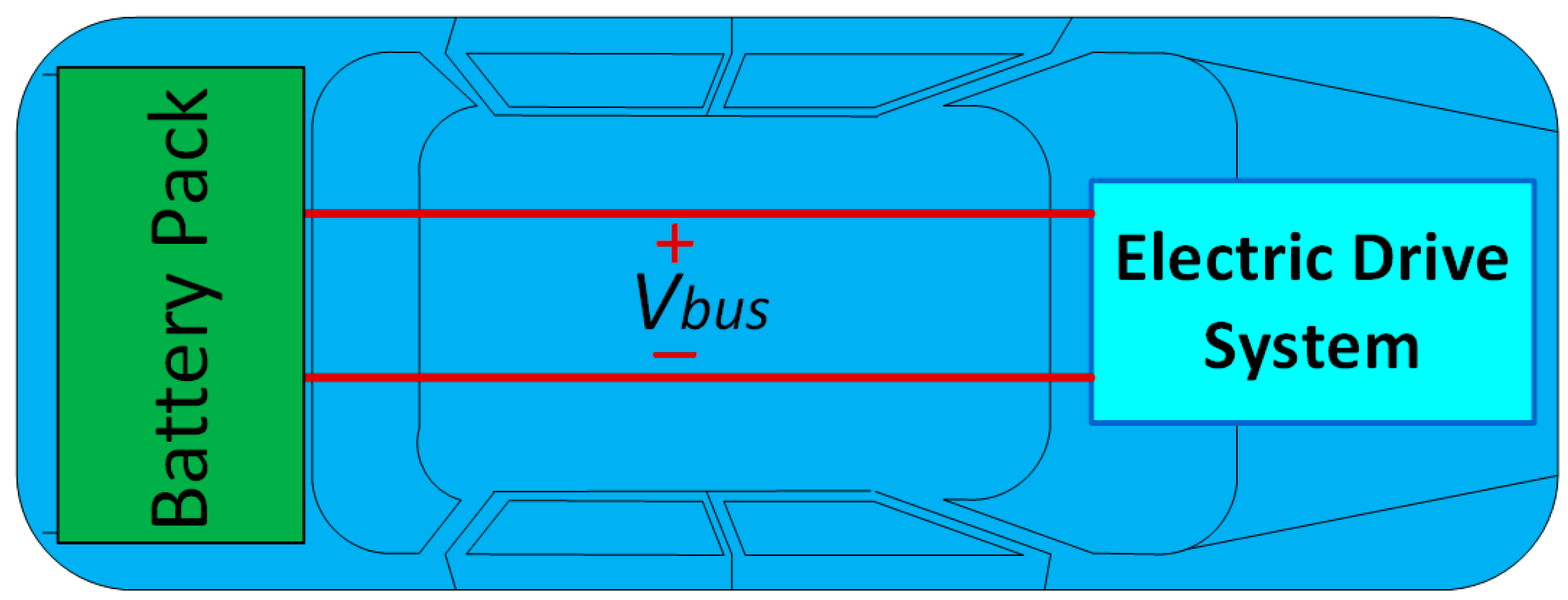
Figure 2.
Illustration diagrams for the presented WEDES system (Wirelessly Distributed and Enabled System) for EV application: (a) EV with example WEDES-MX modules (the modules in the WEDES system named WEDES-MX1 through WEDES-MXN) and OBU (On-Board Unit); (b) WEDES-MX module example mechanical design; and (c) example host slots of the OBU.

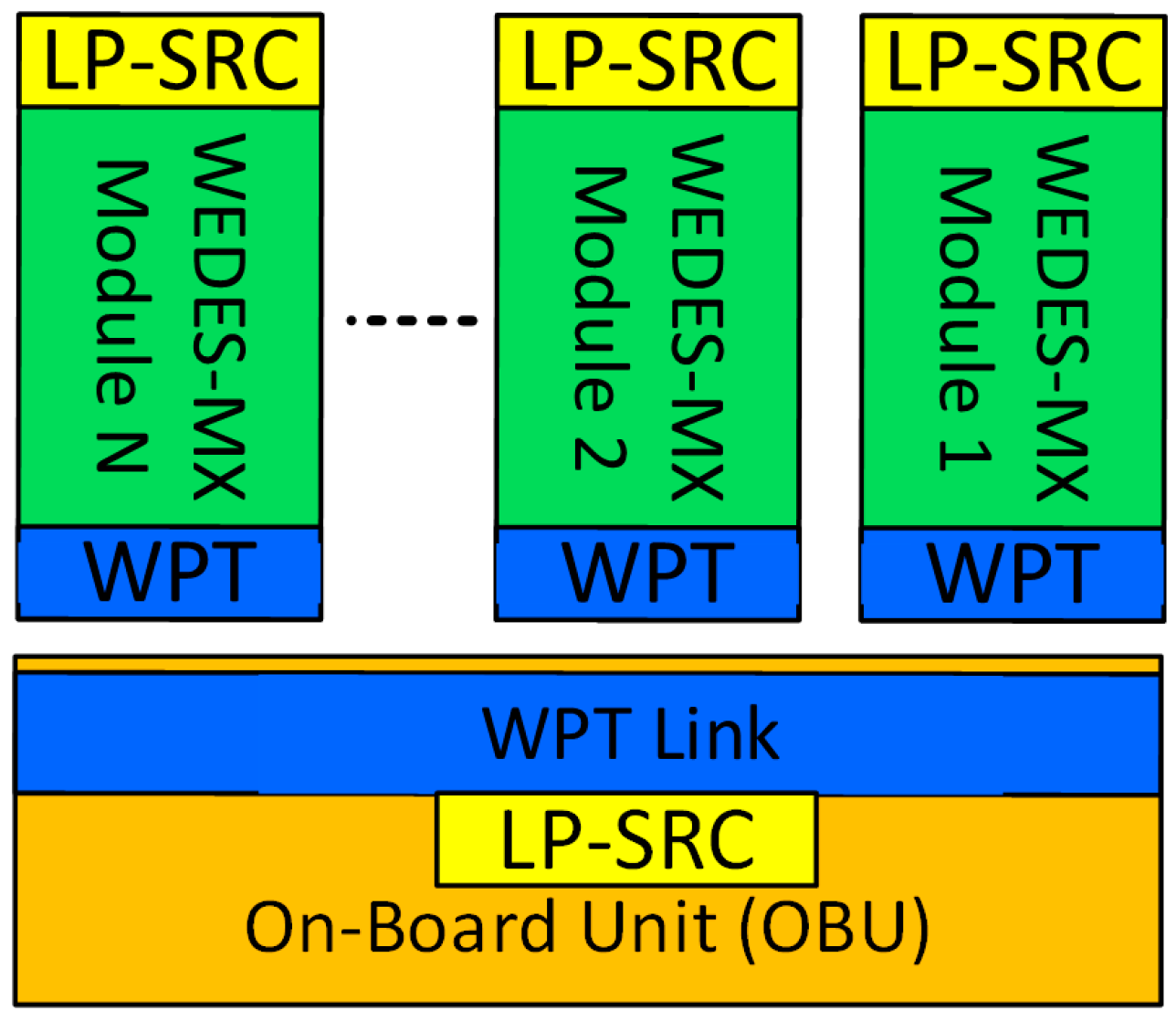
Figure 3.
Block diagram to illustrate the general WEDES system concept and architecture.

Figure 4.
Illustration showing block diagram of a possible internal structure/configuration for WEDES-MX modules and OBU (On-Board Unit) of the WEDES system (power electronics, WPT (Wireless Power Transfer), communications, ..., etc.).
Figure 4.
Illustration showing block diagram of a possible internal structure/configuration for WEDES-MX modules and OBU (On-Board Unit) of the WEDES system (power electronics, WPT (Wireless Power Transfer), communications, ..., etc.).

Figure 5.
Illustration of simplified schematics of an example implementation for the WEDES system power electronics (see also Figure 4 and Figure 6).

Figure 6.
Diagram of the Wirelessly Distributed WEDES Controller: Black/dark color indicates being part of the OBU and blue/light color indicates being part of WEDES-MX modules.
Figure 6.
Diagram of the Wirelessly Distributed WEDES Controller: Black/dark color indicates being part of the OBU and blue/light color indicates being part of WEDES-MX modules.

Figure 7.
An illustration diagram for the timeline of the experiment.
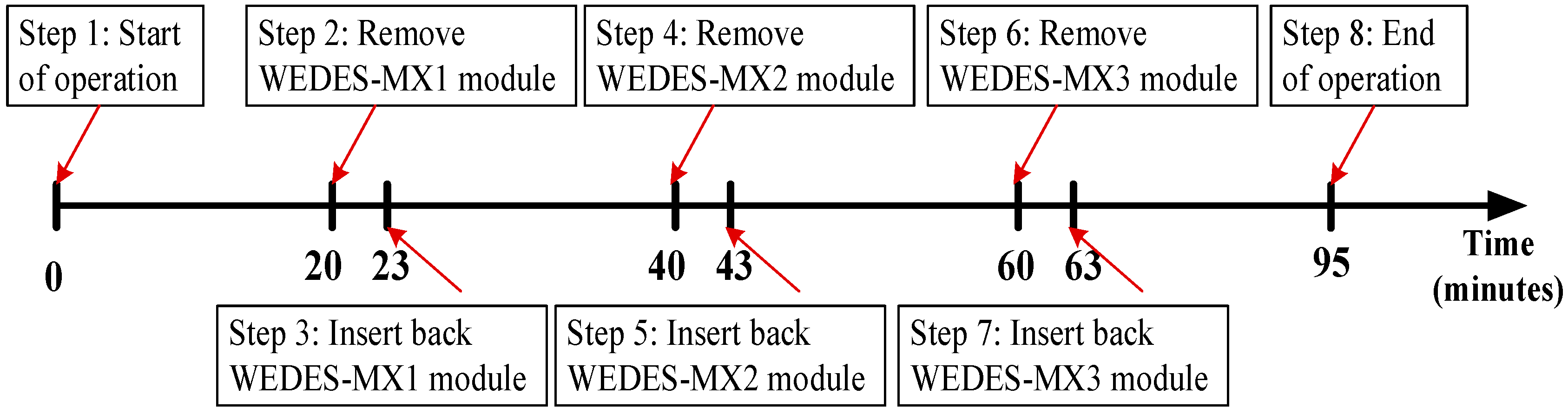
Figure 8.
Experimental results for the SOC values (SOCMX1, SOCMX2, and SOCMX3) of the three WEDES-MX modules during discharging: (a) Full discharge cycle; (b) zoom-in view during time 1–10 min (during initial SOC balancing); and (c) zoon-in view during time 15–35 min (when WEDES-MX1 is removed/disabled then inserted/enabled).

Figure 9.
Experimental results for the weighting factor values (λDC1, λDC2, and λDC3) of the three WEDES-MX modules during discharging: (a) Full discharge cycle; (b) zoom-in view during time 1–10 min (during initial SOC balancing); and (c) zoon-in view during time 15–35 min (when WEDES-MX1 is removed/disabled then inserted/enabled).
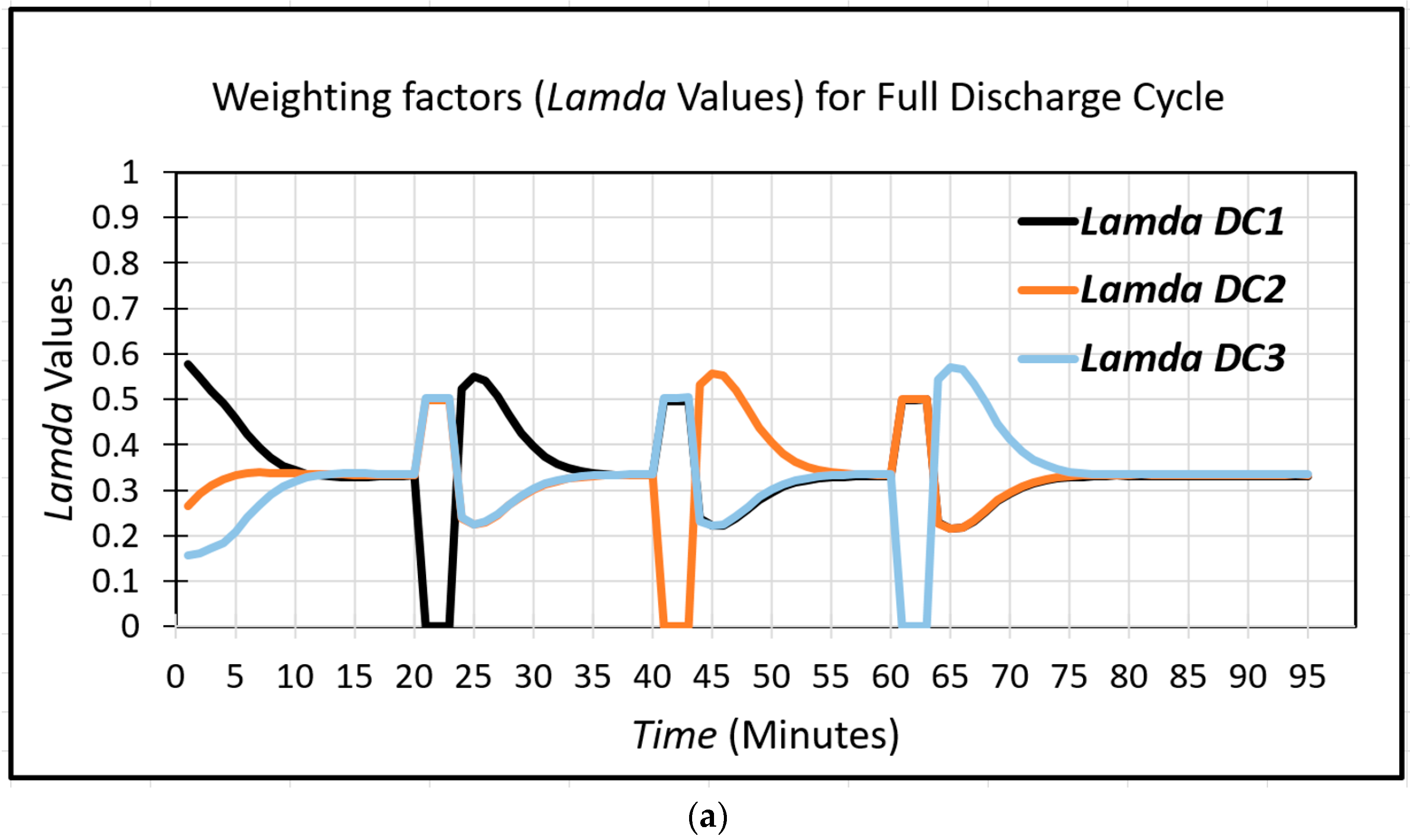
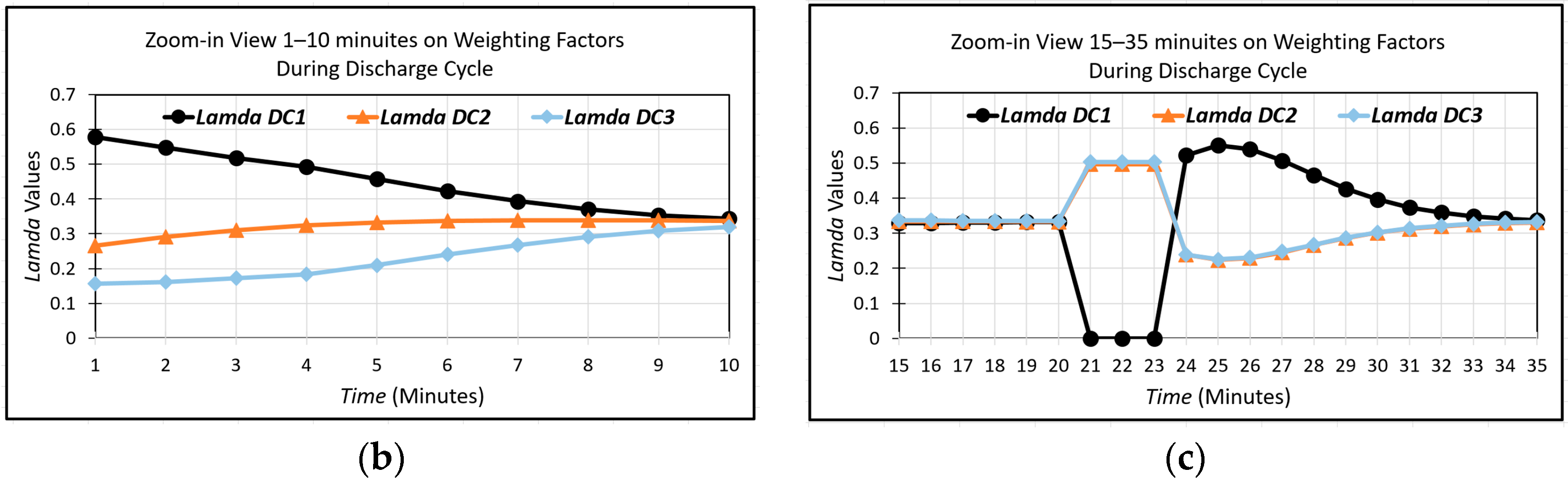
Figure 10.
Experimental results for the bus voltage Vbus and the three OBU voltages (Vo1, Vo2, and Vo3) that form/their sum is Vbus (refer to Figure 5).
Figure 10.
Experimental results for the bus voltage Vbus and the three OBU voltages (Vo1, Vo2, and Vo3) that form/their sum is Vbus (refer to Figure 5).


Table 1.
A summary of battery pack design information for Nissan Leaf 2018 and a possible alternative WEDES battery system (Wirelessly Enabled and Distributed battery system) design (example 1 with 24 modules).
Table 1.
A summary of battery pack design information for Nissan Leaf 2018 and a possible alternative WEDES battery system (Wirelessly Enabled and Distributed battery system) design (example 1 with 24 modules).
| Nissan Leaf 2018 Battery Pack Specifications [27,28,29] | WEDES System Design Example for Nissan Leaf 2018 | ||
|---|---|---|---|
| Battery cell | Cell type | AESC Lithium-ion battery [28] | AESC Lithium-ion battery [28] |
| Nominal voltage | 3.65 V | 3.65 V | |
| Nominal capacity | 56.3 Ah | 56.3 Ah | |
| Battery module | Connection within module | Each module has 8 cells 4s2p | Each module has 8 cells 4s2p |
| Nominal capacity | 450.4 Ah, ≈1.644 kWh | 450.4 Ah, ≈1.644 kWh | |
| Whole battery pack | Connection | 24 battery modules connected in series | 24 WEDES-MX battery modules that are not connected themselves but are connected in series at the receiving OBU after receiving power wirelessly |
| Power transfer type within system | Wired power transfer | Wireless power transfer | |
| kWh capacity | 8 × 24 × 3.65 × 56.3 = 39.455 kWh ≈ 1.644 kWh/module | 8 × 24 × 3.65 × 56.3 = 39.455 kWh ≈ 1.644 kWh/module | |
| Total output voltage (Vbus) | Not regulated ≈ 300 V–400 V range (≈350 V nominal) | Regulated at a desired value (e.g., 350 V) | |
Table 2.
A summary of battery pack design information for Nissan Leaf 2018 and a possible alternative WEDES battery system design (example 2 with 12 modules).
Table 2.
A summary of battery pack design information for Nissan Leaf 2018 and a possible alternative WEDES battery system design (example 2 with 12 modules).
| Nissan Leaf 2018 Battery Pack Specifications [27,28,29] | WEDES System Design Example for Nissan Leaf 2018 | ||
|---|---|---|---|
| Battery cell | Cell type | AESC Lithium-ion battery [28] | AESC Lithium-ion battery [28] |
| Nominal voltage | 3.65 V | 3.65 V | |
| Nominal capacity | 56.3 Ah | 56.3 Ah | |
| Battery module | Connection within module | Each module has 8 cells 4s2p | Each module has 16 cells 4s4p or 8s2p |
| Nominal capacity | 450.4 Ah, ≈1.644 kWh | 800.8 Ah, ≈3.288 kWh | |
| Whole battery pack | Connection | 24 battery modules connected in series | 12 WEDES-MX battery modules that are not connected themselves but are connected in series at the receiving OBU after receiving power wirelessly |
| Power transfer type within system | Wired power transfer | Wireless power transfer | |
| kWh capacity | 8 × 24 × 3.65 × 56.3 = 39.455 kWh ≈ 1.644 kWh/module | 16 × 12 × 3.65 × 56.3 = 39.455 kWh ≈ 3.288 kWh/module | |
| Total output voltage (Vbus) | Not regulated ≈ 300 V–400 V range (≈350 V nominal) | Regulated at a desired value (e.g., 350 V) | |
© 2018 by the authors. Licensee MDPI, Basel, Switzerland. This article is an open access article distributed under the terms and conditions of the Creative Commons Attribution (CC BY) license (http://creativecommons.org/licenses/by/4.0/).
Share and Cite
MDPI and ACS Style
Abu Qahouq, J.; Cao, Y. Control Scheme and Power Electronics Architecture for a Wirelessly Distributed and Enabled Battery Energy Storage System. Energies 2018, 11, 1887. https://doi.org/10.3390/en11071887
AMA Style
Abu Qahouq J, Cao Y. Control Scheme and Power Electronics Architecture for a Wirelessly Distributed and Enabled Battery Energy Storage System. Energies. 2018; 11(7):1887. https://doi.org/10.3390/en11071887
Chicago/Turabian StyleAbu Qahouq, Jaber, and Yuan Cao. 2018. "Control Scheme and Power Electronics Architecture for a Wirelessly Distributed and Enabled Battery Energy Storage System" Energies 11, no. 7: 1887. https://doi.org/10.3390/en11071887
Note that from the first issue of 2016, this journal uses article numbers instead of page numbers. See further details here.