2.2. Overview of the Simulation
To accurately analyze the heat transfer between the ground heat exchanger and the soil, a groundwater and heat transfer model (FEFLOW) was used. This simulation code is based on the finite element method and is widely used in the fields of groundwater movement and pollution. It can be used to analyze the transfer of geothermal and groundwater within the soil [
20]. The simulation model was built by three-dimensional modeling that satisfies three laws, namely conservation of mass (Equation (1)), conservation of momentum (Equation ((2)), and conservation of energy (Equation ((3)), which classify the ground with three phases of solid, liquid and gas [
21].
Law of conservation of mass:
Law of conservation of momentum:
Law of conservation of energy:
Heat Flux is described as follows:
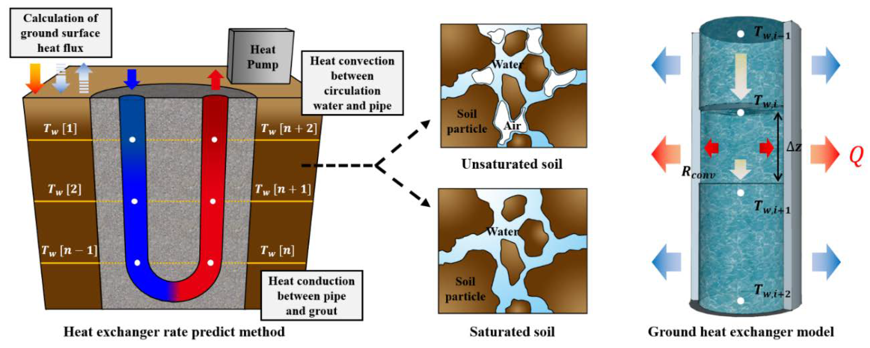
Equation (5) presents the calculation model of a ground heat exchanger. It is based on the one-dimensional advection diffusion equation to calculate the temperature of the pipe surface and the circulation water at each depth point.
One-dimensional advection diffusion equation:
In the one-dimensional advection diffusion equation, convective heat transfer can be expressed as Equation (6), and Equation (7) presents Nusselt number in circulating water turbulent flow inside the GHX that Dittus–Boelter devised.
Convective heat transfer:
Nusselt number:
here,
n is 0.3 and 0.4 for cooling and heating, respectively. The ground surface heat balance model consists of solar radiation, sky radiation, ground surface radiation, convection and evaporation. The validity of the coupled simulation method was verified by comparative analysis with the verification experiments in the previous research [
22].
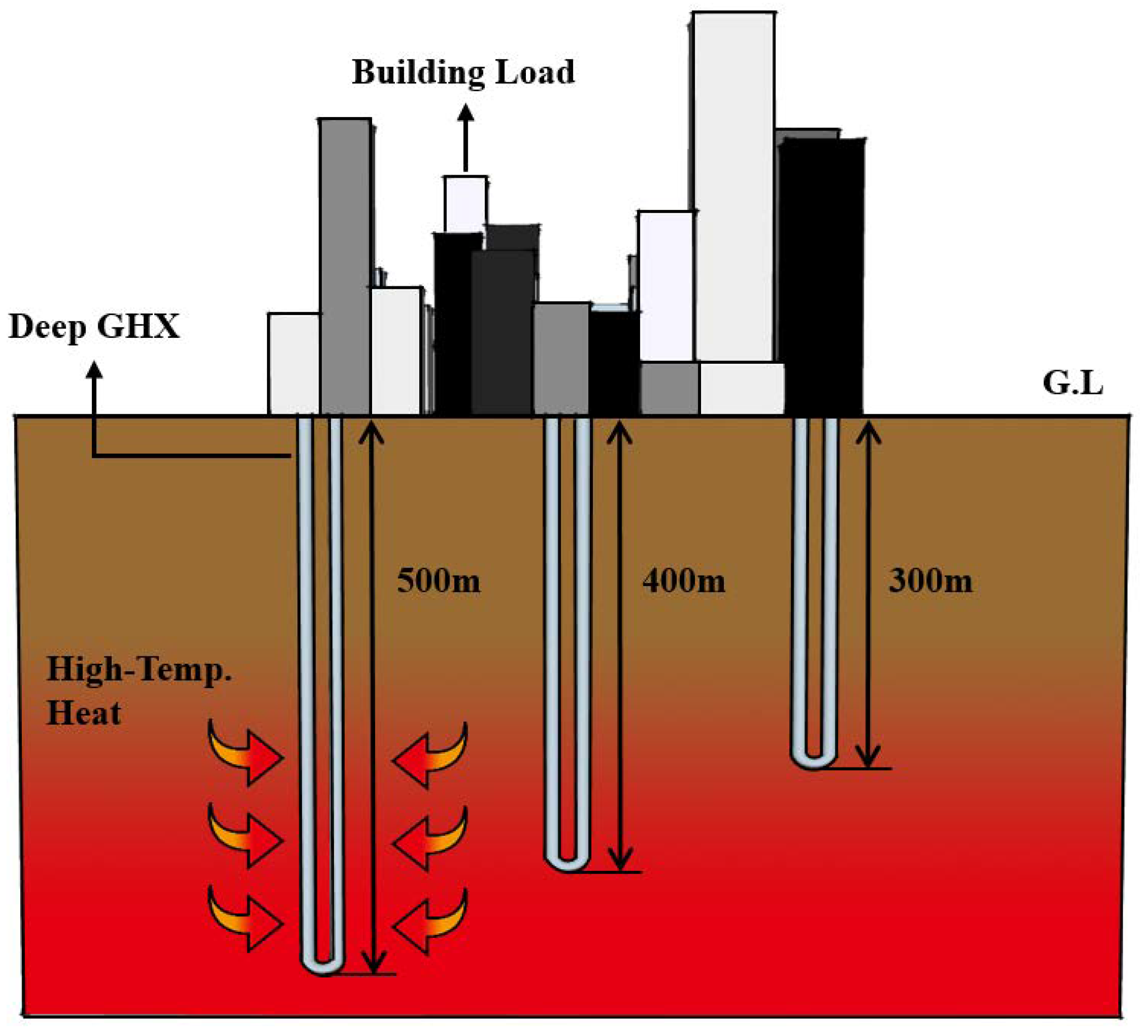
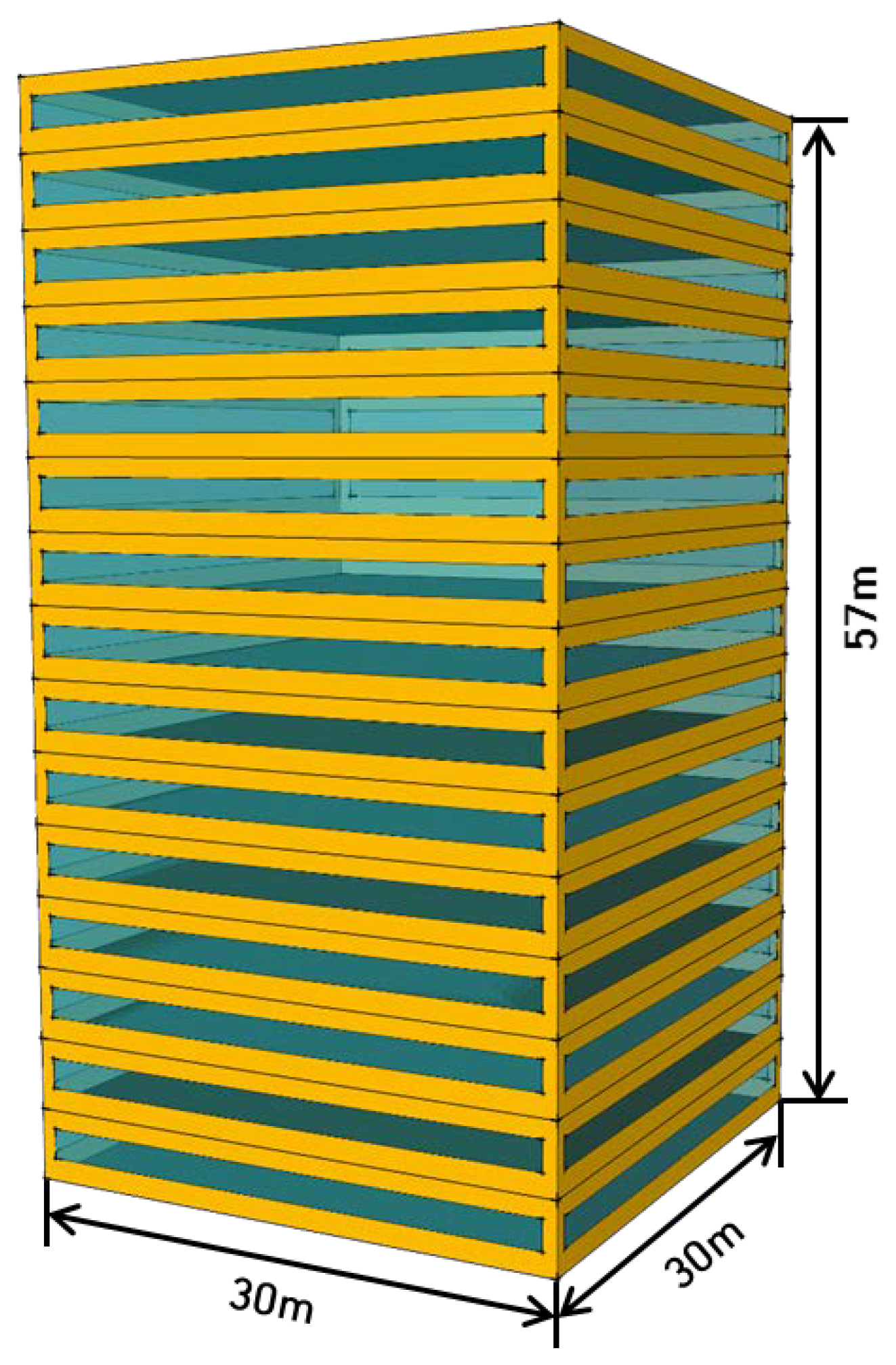
Figure 2 shows the outline of analysis method in this study. The system used in this study consists of the GSHP system coping with the cooling and heating load of the building and the deep ground heat exchanger being able to extract a high-temperature heat source. The deep ground heat exchanger was set as one vertical-closed type with 300 m, 400 m and 500 m depth, respectively. The simulation was conducted using a numerical analysis model to accurately predict the ground heat exchange rate.
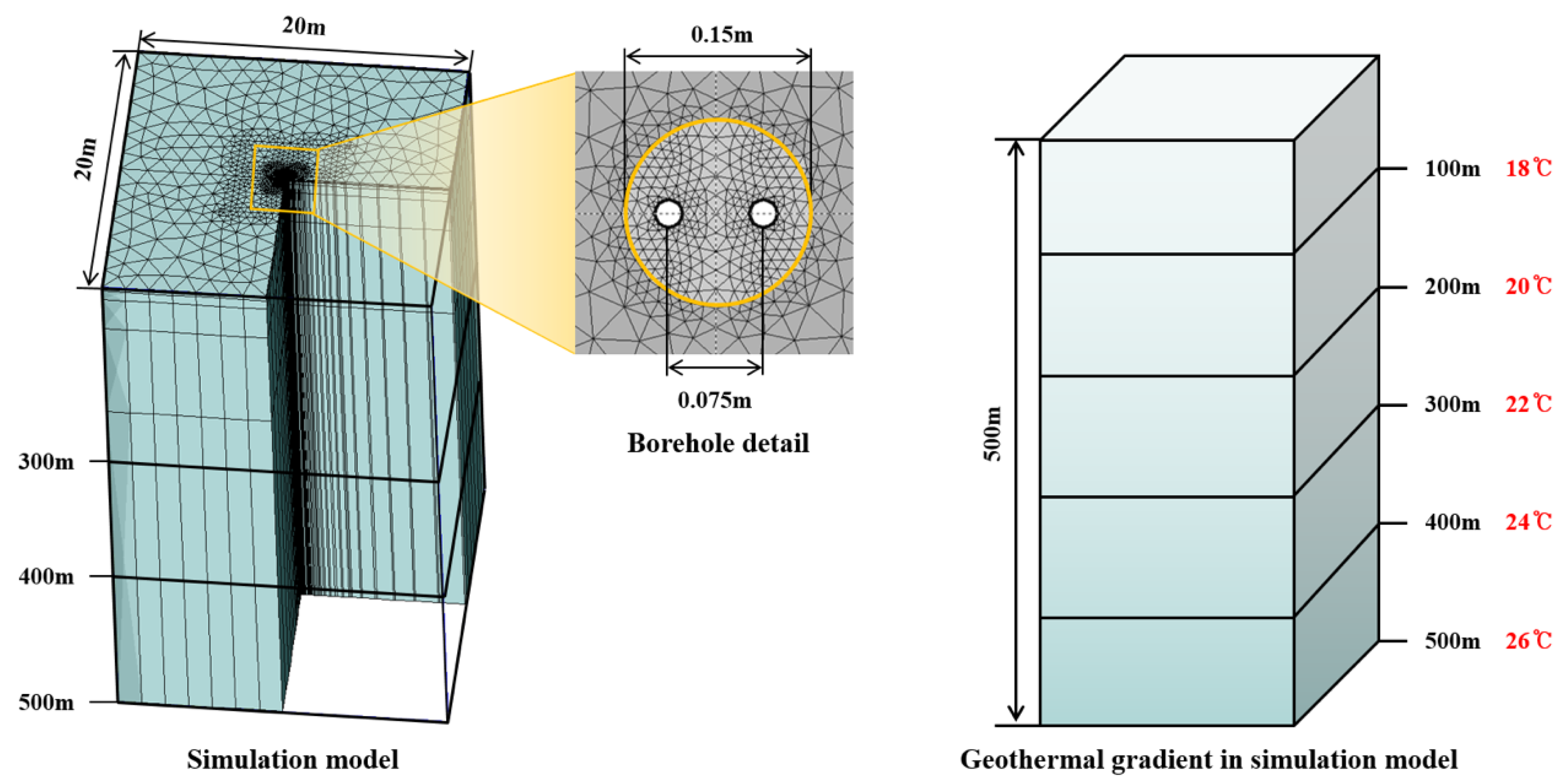
Figure 3 shows an analysis model to predict underground heat exchange rate of the GSHP system using the deep ground heat exchanger used in this study. To make sure the accuracy of predicting the heat extraction rate of the system, “Tetra-mesh” was utilized in the model to construct soil, grout and U-tube form. With analysis range of 20 m × 20 m, three analysis models were constructed depending on the borehole depth, at 300 m, 400 m, and 500 m. The borehole of 0.15 m diameter was installed at the center of the analysis area, grouted with concrete, and inserted with the ground heat exchanger (Single U-tube 50 A, Inner diameter: 0.0454 m, Outer diameter: 0.05 m). The spacing between the U-tubes was set as 0.075 m in consideration of the thermal interference between the ground heat exchangers. It was assumed that the ground condition was granite, which is the bed rock in South Korea, and the conditions for thermal property values of soil, grout and ground heat exchanger are shown in
Table 1.
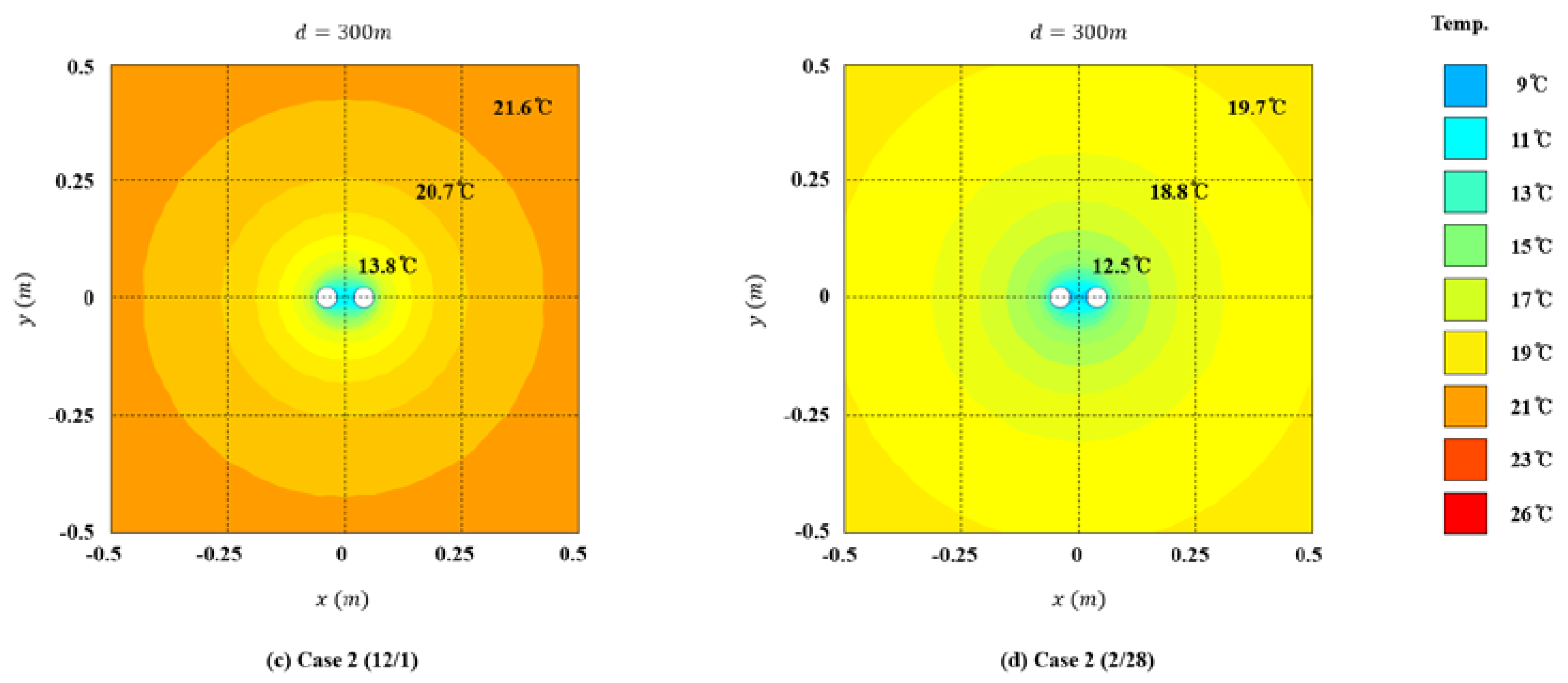
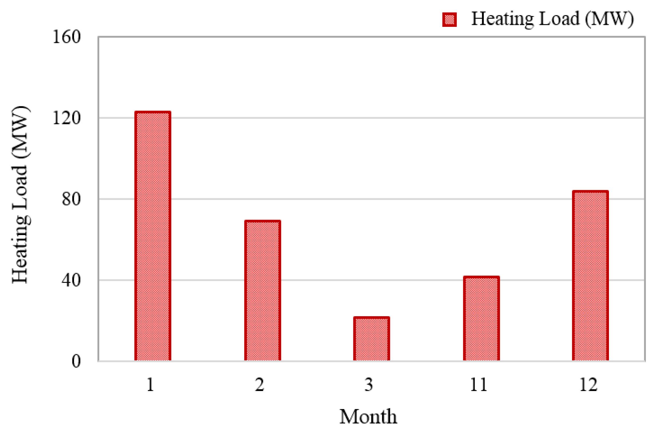
It was assumed that the system operation time is 9 h from 9:00 to 18:00, and the operation period is three months of winter for heating from 1 December to 28 February. The geothermal gradient can be described as the rate of the temperature difference according to the depth of the ground.
However, in this study, the initial underground temperature was set as 16 °C, and it increased 0.02 °C per meter based on the average geothermal gradient of South Korea. The three-dimensional numerical analysis model divided each layer with the depth of the ground heat exchanger, and the geothermal gradient values were applied on it.
Table 2 represents the case study conditions.
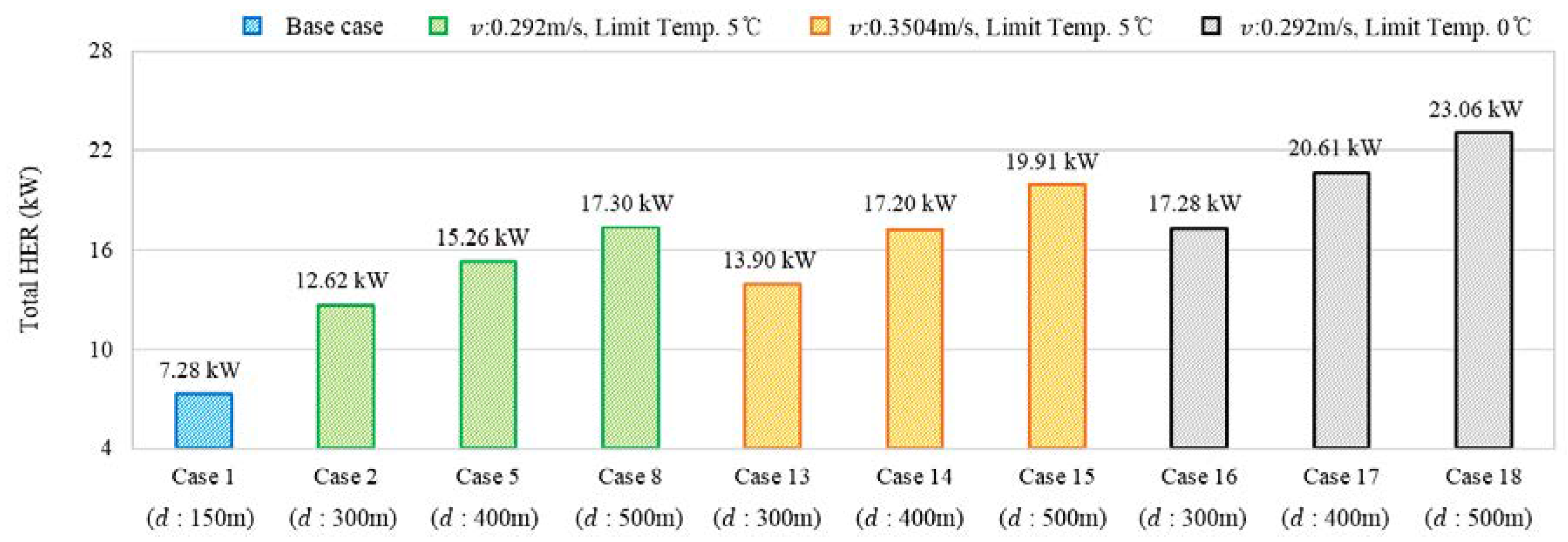
The case study of the GSHP system using the deep ground heat exchanger was conducted on the following design factors: ground heat exchanger depth, thermal conductivity, geothermal gradient, flow rate, system and limit temperature to accurately estimate the performance of the heat exchange rate. The numerical simulation model was set as 500 m, 400 m, and 300 m, respectively, to compare the effect of the depth of the ground heat exchanger on the performance of the heat extraction, and this study quantitatively analyzed the amount of heat exchange rate with different design factors.
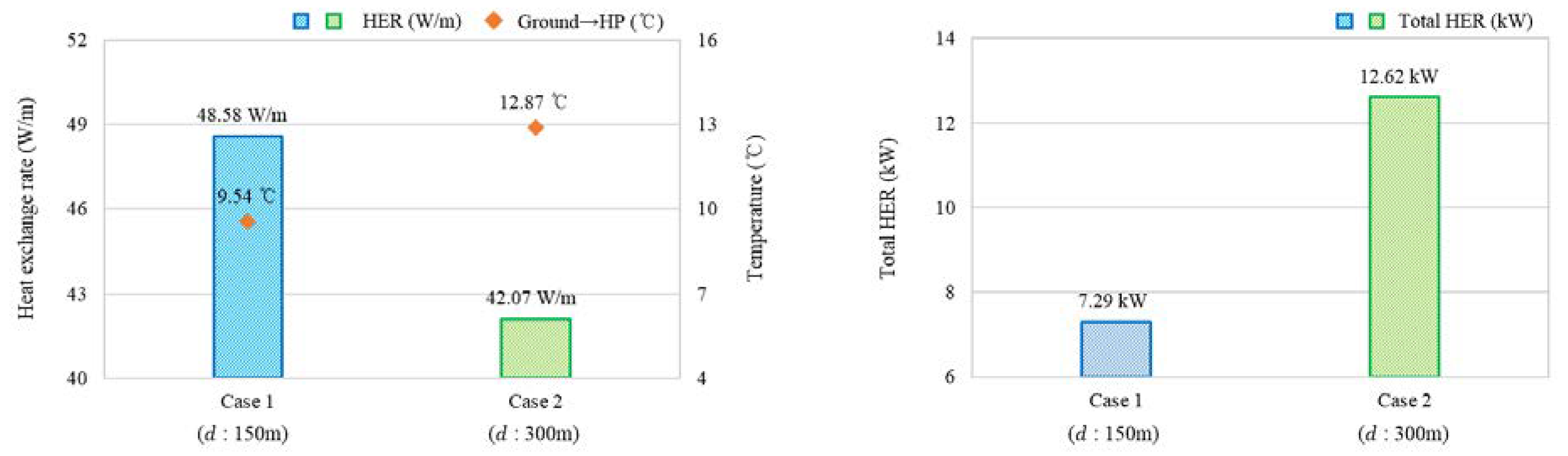
Case 1, which describes a commonly-spread vertical type geothermal system, was used to evaluate and compare the performance of a geothermal system using a deep groundwater heat exchanger.
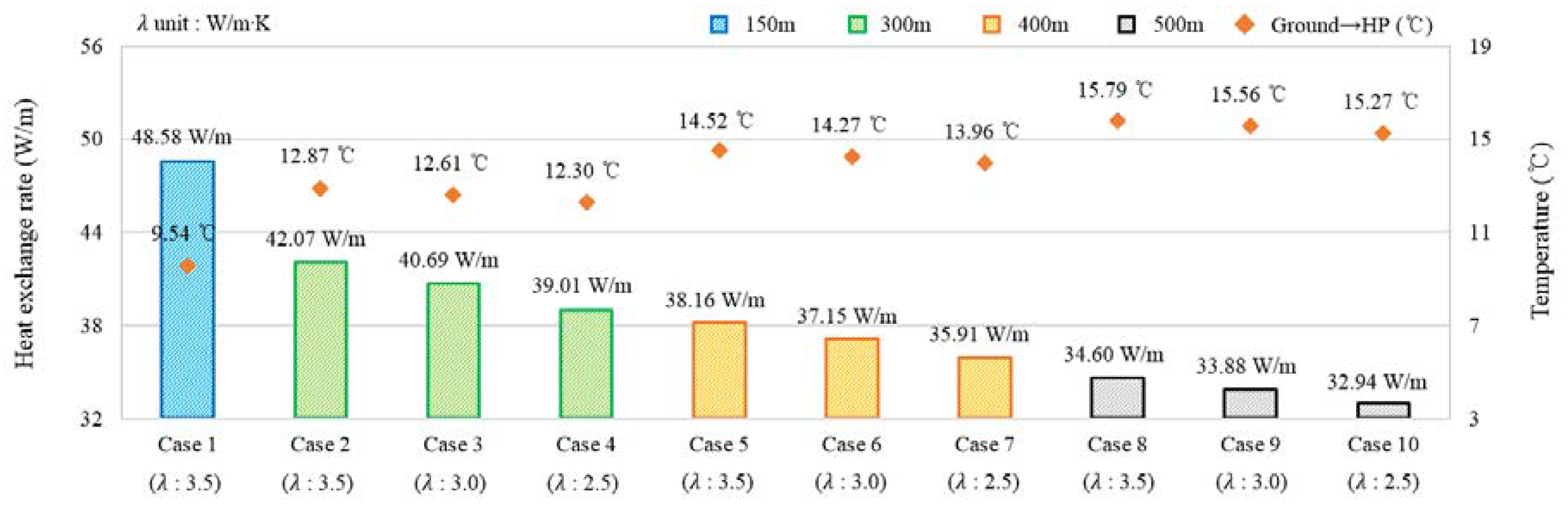
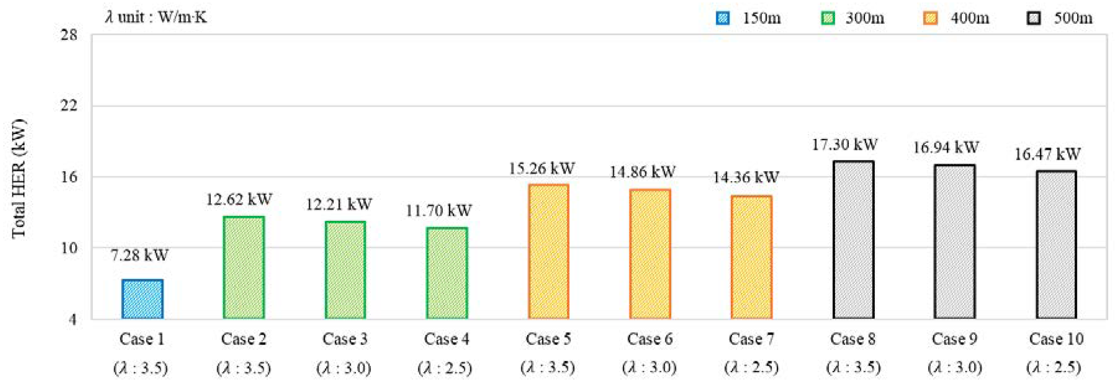
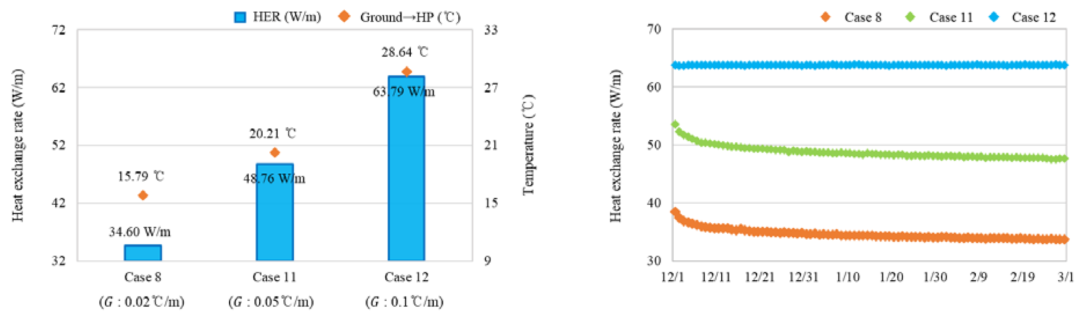
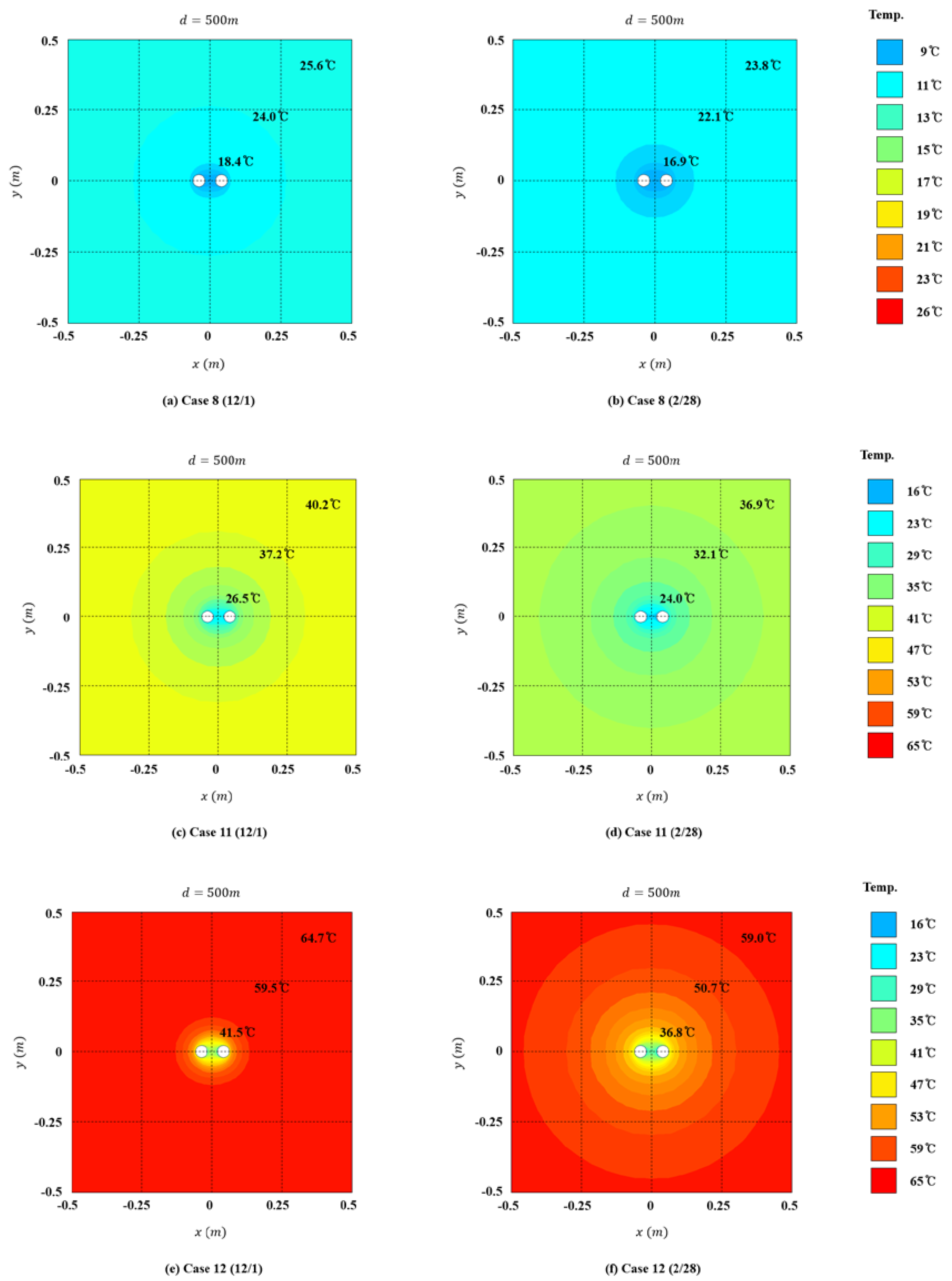
In general, the ground thermal conductivity has the greatest influence on the vertical closed GSHP system, and it also works as a key design factor to improve the performance of the deep ground heat exchanger. In Case 2, the ground thermal conductivities of three cases were set as 3.5 W/m·K, 3.0 W/m·K and 2.5 W/m·K, respectively, which is applied to Case 10, to analyze the heat extraction performance of the GSHP system according to the ground thermal conductivity. Cases 11 and 12 were utilized to analyze the possibility of the introduction and the underground heat extraction of the system according to the geothermal gradient, when a deep ground heat exchanger is installed in a region where the temperature slope of the geothermal gradient is high. The heat exchange rate of the GSHP system is defined by Equation (9).
In Equation (9), it is possible to recognize that the heat exchange rate of the GSHP system is proportional to the heat source water flow rate. This way, an increase in the flow rate of the heat source water represents the heat exchange rate of the GSHP system to increase. In Cases 13–15, the flow rate of the heat source water was set to 0.3504 m/s in each depth of the ground heat exchanger, to analyze its influence on the performance of the heat extraction. Besides, the heat source water was set to prevent the decrease of underground temperature during the system operation. In general, the limit temperature of the heat source water is set to 5 °C; however, this study sets the heat source water temperature to 0° in Cases 16–18 considering the use of deep heat exchanger supplying a high temperature heat source.


