A Cascaded Multilevel Inverter Using Only One Battery with High-Frequency Link and Low-Rating-Voltage MOSFETs for Motor Drives in Electric Vehicles


School of Automation, Beijing Institute of Technology, Beijing 100081, China
*
Author to whom correspondence should be addressed.
Energies 2018, 11(7), 1778; https://doi.org/10.3390/en11071778
Submission received: 6 June 2018
/
Revised: 26 June 2018
/
Accepted: 3 July 2018
/
Published: 6 July 2018
Abstract
:Cascaded H-bridge (CHB) multilevel inverters are widely used in industrial applications, such as medium-voltage conversion and motor drives. However, the DC bus voltage in the electric vehicles is limited and it might not meet the requirements of the inverters for conventional motor drives. This paper presents a solution to drive the conventional motor (3Φ/AC 220 V) with inadequate DC bus voltage (DC 144 V) in an electric vehicle without any extra step-up circuits. The solution consists of a CHB inverter as a motor drive and a high-frequency (HF) transformer to balance the voltage. The multilevel CHB inverter improves the voltage and the current waveforms. High-frequency link (HFL) is used to create several isolated DC sources for the system and it can improve the power density. Besides, it replaces bulky line-transformers in the conventional CHB inverters, and the volume is reduced. Also, the inverter has bidirectional power flow ability, which can improve the efficiency in motor drives. As a result, the reduction of the step-up circuits is achieved and the topology can be used in the electric vehicles that are powered by only one 144 V-battery. The details and the principles of the control algorithm is discussed and an experiment based on a four-level CHB inverter with one DC 30 V power source is carried out to validate the proposed characteristics.
1. Introduction
In electric vehicles, one of the typical battery rating voltages is 144 V. In order to meet the voltage requirements, 600 V-IGBTs (Insulated Gate Bipolar Transistor) is usually adopted, which increases the cost of the inverter [1]. As a result, an inverter consisting of low-rating-voltage MOSFETs is proposed in the paper to decrease the cost, meet the voltage requirements, carry out the power conversion, and drive the motor.
Multilevel inverters have gained much attention and are very popular nowadays. People can realize high-voltage power conversions with low-voltage power electric devices [2,3], while the inverter in [2] drops to two-level output at high-frequency, and in [3], full-bridge in series with level doubling network is used to achieve multilevel output and several isolated sources are needed. The CHB inverters are used widely in the market because of their high modularity, low derivative voltages, low total harmonic distortion (THD), high DC-AC gain, and et al [4,5,6], also corresponding control algorithm is adopted, such as passivity-based control (PBC) [4], model predictive control (MPC) [5], and simplified small-signal model [6]. A large range of voltage and power capacity can be achieved based on CHB inverters. However, some drawbacks still exist in CHB inverters, such as the line-frequency transformers and a lack of bidirectional power flow ability [7,8]. Also, a large number of isolated DC supplies are need in the CHB inverter; hence, the outputs of the H-bridges can be connected in series to raise the voltage [9].
Some solutions to overcome the disadvantages of CHB have been proposed, such as the use of high-frequency transformers [10,11,12], floating capacitors as supplies [13,14], pulse width modulation (PWM) rectifiers [15,16], hybrid DC sources [17,18], and double level circuit [19]. A modified high- frequency phase disposition pulse width modulation (PDPWM) technique is proposed in [10], the total harmonic distortion (THD) performance is improved. A 15-level high-frequency ac-link single-stage asymmetrical topology in [11] and high-frequency-link DC transformer in [12] are adopted to reduce the system size. Floating capacitors instead of isolated sources in [13,14] are used to reduce the device count. PWM technique is utilized in [15,16] to improve the performance of voltage balancing of the DC links at low-frequency. Hybrid multi-cell converter (HMC) are used to generate a positive variable dc-link voltage in [17,18], and the output waveforms are improve in a large range. Combination of a double level circuit in [19], the output voltage level is increased nearly twice, while the device count is increased either. These solutions focus on the partial drawbacks and they cannot meet the requirements of the motor drives in electric vehicles, in which there is only one DC power source and the voltage is comparatively low to drive conventional motors directly. Output transformers are introduced in some occasions to raise the voltage [20], but they can only be used when the frequency is constant, such as in SVCs (Static Var Compensator), SVGs (Static Var Generator), and APFs (Active Power Filter). The line-frequency transformers are not eliminated.
This paper proposes a solution to eliminate the line-frequency transformers in CHB inverters and to inherit the advantages, such as high modularity and low THD. The characteristics of the proposed topology are as follows: (1) Only one DC power is needed; (2) The line-frequency transformer is replaced with a high-frequency transformer; (3) bidirectional power flow is available; (4) high modularity and easy to expand; and, (5) HFL and high power density. The output voltage can be raised with more H-bridges.
A main H-bridge and a multi-winding high-frequency transformer are introduced in the topology to generate the isolated DC supplies for all of the H-bridges. The DC bus voltages in every H-bridge can be controlled by regulating the high-frequency voltages on the windings of the high-frequency transformer [21]. A three-phase inverter is powered in parallel by the input DC source [22], while several non-isolated or isolated power supplies are needed. A number of H-bridges, which have the same parameters, are connected in series to form a string that can generate multilevel voltages. All of the three-phase H-bridge strings are connected to the three-phase inverter in Y-type [23]. PWM strategy can be used to generate the gate signals and to achieve multilevel output waveforms in a large range [24].
This paper is organized as follows: The structure of the inverter is discussed in Section 2. The control of the power flow in the high-frequency transformer is studied and the PWM strategy is established to minimize the THD in Section 3. Section 4 shows the experimental results. The comparison with relevant works is given in Section 5, and the conclusion is given in Section 6.
2. Proposed CHB Multilevel Inverter
2.1. Topology Analysis
Figure 1 shows the proposed CHB multilevel inverter using a high-frequency transformer and several HF H-bridges to generate isolated DC supplies. The H-bridges, which are connected to the high-frequency transformer directly, are named as high-frequency H-bridges because their switching frequency is 20 kHz. The other H-bridges are named as low-frequency H-bridges with switching frequency at 5 kHz. The high-frequency link consist of several HF H-bridges and a HF transformer. It aims to control all of the DC bus voltages, which are the supplies of the low-frequency H-bridges. The aim of HF on HFL side is to reduce the volume of the transformer and increase the power density, while the aim of the low-frequency on the motor drive side is to reduce the switching losses, increase the efficiency, and guarantee better harmonic features.
As shown in Figure 1, the high-frequency link replaces the line-frequency transformer and diode/PWM rectifiers in conventional CHB inverters. There are several windings on the high-frequency transformer to generate isolated DC supplies. Each winding is connected to a high-frequency H-bridge, by which the high-frequency voltage is converted into DC voltage. More windings and high-frequency H-bridges can be introduced on the CHB inverter to enhance the output voltage levels. Figure 1 shows a four-level CHB inverter and all of the DC bus voltages (VDC–1~VDC–4) are equal to VDC. With respect to the mid-value of the input source, the output voltages on each phase can be four levels: −1.5VDC, −0.5VDC, 0.5VDC, and 1.5VDC.
The entire system is powered by one DC source, and can produce single-phase, three-phase, or multi-phase voltages if necessary. The proposed topology can be implemented in a large number of applications, as shown in Table 1, where usually there is only one DC supply and the DC voltage cannot be too high. For example, in the micro-grids, electric cars, buses and trucks, batteries, fuel cells, or super capacitors are usually used for motor drives. The DC voltages are comparatively low and conventional step-up converters (e.g., boost converter) cannot provide high DC-AC gain for the system.
2.2. Output Voltage and Modulation Strategy
The inverter proposed in Figure 1 can be modulated with overlapped PWM strategy. As shown in Figure 2, vref is the reference voltage of phase-A in the inverter. It was divided into two parts: vref(0) and vref(1), which are used to generate the gate signals.
For N CHB in each phase, the amplitude of the reference voltage can be as high as:
Thus, for the three-phase systems, the line RMS voltage Vmax can be calculated in (2), when N = 1.
Thus, the converter can drive the 220 V motor when it is powered by the 144 V battery.
The reference voltages for the three-phase full bridge inverter and the H-bridges are denoted as vref(0), vref(1), … vref(N), and they are:
where
When there are more H-bridges in the string, carrier-phase-shifted method can be used to lower the THD and raise the equivalent switching frequency [25]. The phase shifted angle is:
Figure 3a shows how to generate the gate signals based on vref(0), vref(1), and the carrier when |vref| < 0.5VDC. The reference voltage for the H-bridge is set as 0. The three-phase inverter will output the reference voltage. Figure 3b shows how to generate the gate signals based on vref(0), vref(1) and the carrier when |vref| ≥ 0.5VDC. The reference voltage for the H-bridge is set as 0. The three-phase inverter will output the reference voltage. In Figure 3, when the reference signal is higher than the carrier, the MOSFET is turned on. Otherwise, the MOSFET will be off. The switching period is Ts. The two IGBTs in one bridge are working in the complementary mode, hence gk′ = not gk, where k = 1, 2, and 3.
Figure 4 shows the reference voltage and the simulation waveforms of the three-phase output currents. The simulation parameters are shown in Table 2.
As discussed in (2), the line voltage (Root Mean Square, RMS) for the three-phase system can be as high as 265 V when VDC = 144 V in the simulation. It is high enough to drive the motor.
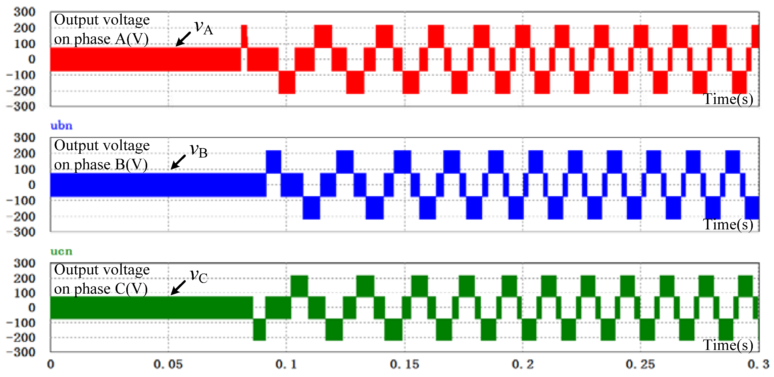
The V/F motor control algorithm is adopted in the simulation. In Figure 4, the frequency rises from 0 to 60 Hz in the first 0.2 s. The waveforms of vref, vref(0), and vref(1) coincide with the analysis in Figure 2. The three-phase currents are sinusoidal. Figure 5 shows the three-phase output voltages. There are four voltage levels: −216 V, −72 V, 72 V, and 216 V. Thus, the topology that is proposed in Figure 1 and powered by only one 144 V DC source can drive the 220 V motors.
2.3. Power Distribution Characteristics
In Figure 2, the reference voltages are different for the half-bridge and H-bridge converters. But, the same current flows through the two converter. Assuming that the current is sinusoidal and the power factor angle is α, when the amplitude of vref is smaller than 0.5VDC, the power released by the H-bridge converter is zero. Hence, the p.u. value is
U is the RMS value of vref and I is the RMS value of the current. When the amplitude of vref is not smaller than 0.5VDC, the equivalent voltage of the H-bridge and the current can be drawn as
In Figure 6, when vref > 0, γ is the phase difference between vref and the equivalent voltage, γ can be calculated as
Thus, the power of the H-bridge can be calculated as
Hence, in Equation (7) can be
The power of the motor is 10 kVA. The RMS value of the rating current can be calculated as I = 10 kVA/220 V/1.732 = 26 A. Figure 7 shows the curves of P1* with different α and vref.
In Figure 8, the peak value of P1* is about 0.6446. It occurs when the amplitude is 180 V and α = 0. Hence, for a 10 kVA system, the overall power of the H-bridge can be 10 × 0.6446 = 6.446 kW. In other words, the capacity of the HF transformer is about 6.446 kW, which is helpful to the design of the HF transformer discussed in the next section.
3. High-Frequency Link
3.1. Concept of the High-Frequency Link
The HFL is a bridge among the H-bridges. The energy flows from the battery to the H-bridges when the motor is accelerating. The HFL can transfer the energy from the H-bridges to the battery when the motor is braking. The operation of the circuit is quite simple because all of the DC bus voltages are equal to VDC. All of the MOSFETs have the same rating parameters. It is easy to maintain the converter because of the high modularity.
Each H-bridge can generate a square waveform of voltage, and the phase of the square waveform is controlled to regulate the power flow. Literature [26] introduced a high-frequency link based on soft magnetic cores. the power is up to 400 kW. In the electric vehicles, the total power can be 10 kW typically. In that case, the power flows through the high-frequency link can be shown in Table 3.
The high-frequency technology means small size, weight, and cost. Figure 8 shows the flux linkage and voltage in the transformer. Since the voltages are square waves, different design should be implemented. The flux linkage is a triangular function because the voltage on the winding is square wave, as shown in Figure 8. The slope of the triangular wave is proportional to the amplitude of the voltage. The flux linkage and voltage can be written as:
where k = 1, 2, 3, …
where N is the number of turns, A is the core area, Bmax is the flux density, and f is the frequency of the square waveform. In the proposed high-frequency transformer, f is equal to 20 kHz and Bmax is constant for the magnetic cores. Thus, N and A can become very small.
The four windings (primary wind W1 and secondary winds W2~W4, the turns ratio is 1:1:1:1) of the transformer in the proposed topology can be described, as in Table 3.
If the core area of the HF transformer is 324 mm2 (18 mm × 18 mm) and the flux density is 0.2 T, the number of turns can be calculated as:
Hence, all of the windings have at least 19 turns. In that case, the maximal voltage can be as high as 144 V. For W1, the maximal current is 45 A. As a result, a 10 mm2 copper wire is enough. For W2~W4, 5 mm2, copper wires are required. Hence the total area of the wires can be 5 × 19 × 3 + 10 × 19 = 475 mm2.
3.2. Control of DC Bus Voltages
The power flows among W1~W4 separately in the system and the equivalent circuit can be drawn, as in Figure 9. The four voltages sources can be replaced with four HF sinusoidal voltages to simplify the analysis.
The mutual inductors are also omitted as it is much smaller than the self-inductor on each winding. The currents flowing out of u1~u4 are i1~i4. N is the number of turns of each winding. im is the equivalent magnetizing current of the core. Thus,
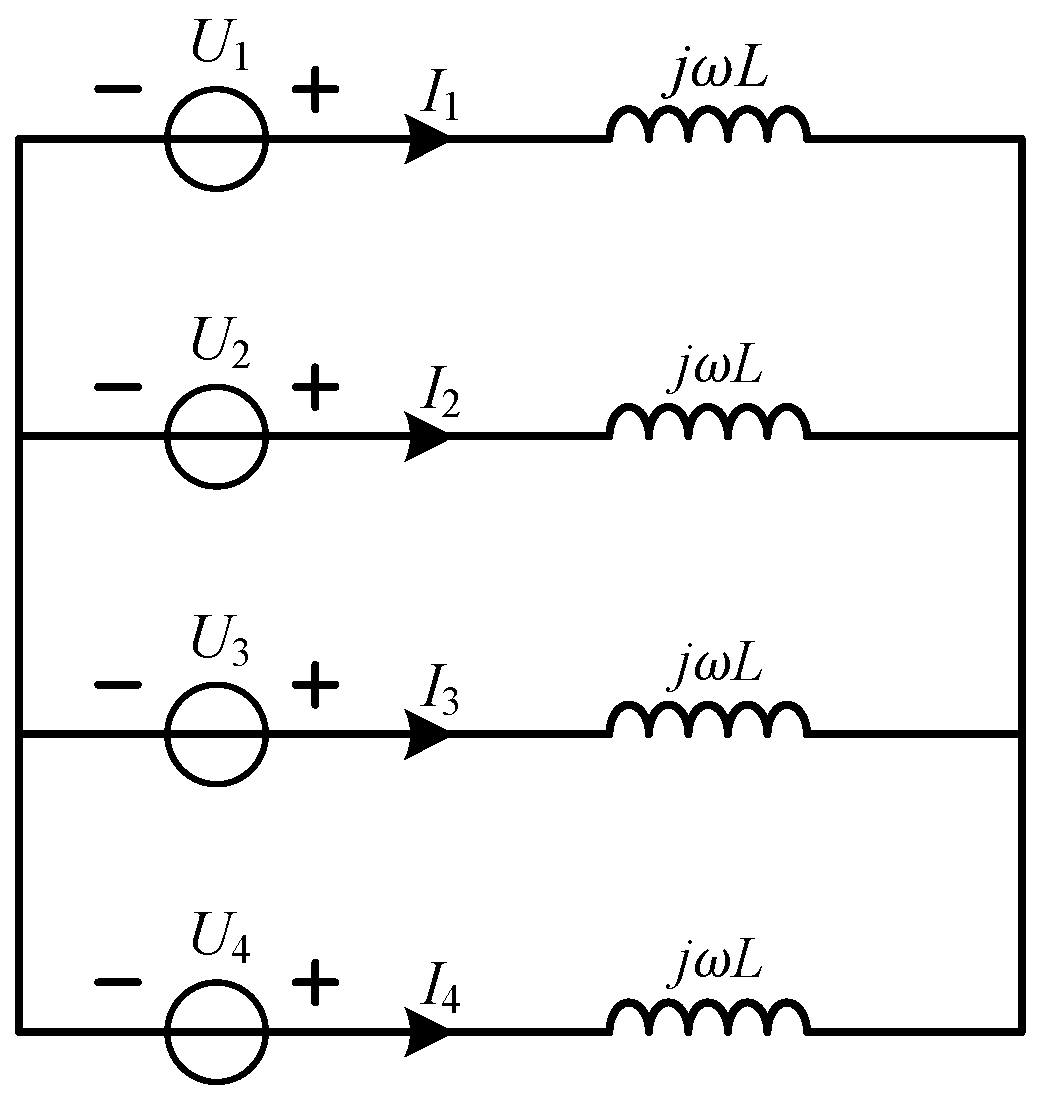
Since all of the windings have the same number of turns, L1 = L2 = L3 = L4 = L. Lm can be removed because im ≈ 0. The equivalent circuit can be shown in Figure 10, where U1~U4 are the voltage phasors of u1~u4 and I1~I4 are the current phasors of i1~i4. The angles of U1~U4 are denoted by β1~β4.
The current phasor Ik (k = 1, 2, 3, 4) can be calculated as
The amplitude of phasor Uk (k = 1, 2, 3, 4) is denoted by Ubase. Hence, the active power released by phasor Uk (k = 1, 2, 3, 4) can be
and
Hence, a larger angle βk will enlarge the active power Pk released by the voltage source. The DC bus voltage VDC–k can be controlled by maintaining Pk, since the DC bus capacitor voltage is considered to be the integration of the active power released by the DC capacitor, as shown in Figure 11 and described in Equation (20), where C is the equivalent capacitance of the DC capacitors.
β1 is set to zero since there are only three independent variables in Equation (17) (P1 + P2 + P3 + P4 = 0, so only three formulas about the active power and angle can be obtained). β2~β4 are generated by the voltage close-loop, as shown in Figure 12, to control VDC–2~VDC–4, respectively. The control algorithm shown in Figure 12 works as follows (k = 2, 3, 4):
- if VDC–k is lower than 144 V, βk goes lower, Pk goes lower, and VDC–k goes higher;
- if VDC–k is higher than 144 V, βk goes higher, Pk goes higher, and VDC–k goes lower; and,
- if VDC–k is equal to 144 V, βk keeps constant, Pk is constant, and VDC–k is constant.
The polarity of the phase-shift angle βk determines the direction of the power flow. Fluctuation occurs when the motor is braking, and in this situation, the motor will charge the H-bridges and cause DC voltage raise on each power cell in each phase. Due to the algorithm above, βk goes higher, Pk goes higher, and the energy is transferred to the input battery through the HFL, and VDC–k goes lower to the set value.
3.3. Magnetic Biasing Suppression
The magnetic biasing will occur if the positive-voltage time span is not equal to the negative-voltage time span for u1~u4. Some factors, such as the dead band, the vibration of the clock, the performance of the driving circuits, and the system delay will deteriorate the symmetry of the square waveforms. Hence, a magnetic biasing suppression method is necessary to keep the system stable.
Take W1, for example, the terminal voltage u1 is divided into two parts: (the DC component) and (the AC component). Hence, the flux linkage in the core ψcore is
Because of the first expression in the Equation (21), the amplitude of ψcore will go higher and higher and make magnetic biasing happen. Even more, the magnetic core will be saturated and the system will fail.
Based on the Gauss Formula, the equivalent magnetizing current im will generate ψcore, and the formula is
where l is the equivalent length in the magnetic core, μr is the relative permeability, and S is the area of the magnetic core.
A low-pass filter can be introduced to observe the DC component, which is exactly an indicator of the magnetic biasing phenomenon, in im. The magnetic biasing suppression algorithm is shown in Figure 13. Typically, the algorithm is made up of two parts, which are the magnetic-biasing observer and voltage-biasing generator. It should be noticed that the magnetic biasing might be generated by all of the windings, but only W1 is used to carry out the suppression method. In this way, the control system is simplified and the reliability can be improved.
4. Experiments
4.1. Experimental prototype introduction
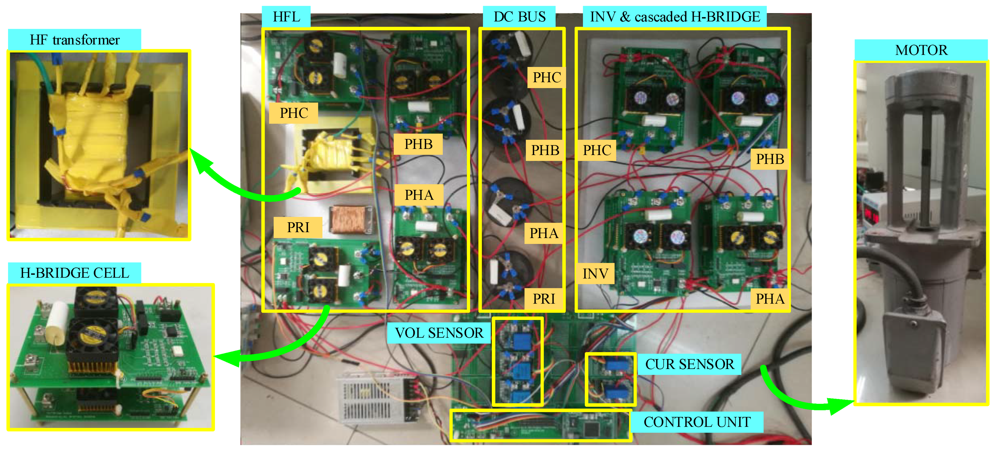
An experimental prototype is built to test the proposed converter. The HFL works with a square waveform of voltage. The frequency is 20 kHz and the amplitude of the voltage is 30 V (equal to the battery voltage). The photo of the prototype is shown in Figure 15.
Figure 15 shows the connection of the proposed inverter (HF transformer: high-frequency transformer, HFL: high frequency link, PRI: primary side, PHA: phase A, PHB: phase B, PHC: phase C, INV: inverter side), the DC bus is obtain by the battery, the HFL and INV and CHBare configured through the basic H-bridge cell. The load is an asynchronous motor. Through the voltage sensor, the DC bus voltage of three phases is sampled to the control unit, with PI (Proportion Integration) controller the phase shift angle is calculated and the power transferred to each phase is obtained, as a result, the DC bus voltage is constant. Through current sensor, the current of PHA and PHB is sampled to the control unit. Through DQ (Direct-Quadrature) transform, the motor is controlled in current close loop.
The parameters of the asynchronous motor is shown in Table 5.
The cost list of the key components is shown in Table 6.
Utilizing multilevel technique, low-voltage MOSFETs are adopted instead of 600 V-IGBTs on the high voltage condition. In the proposed topology, thirty-four MOSFETs, one transformer, and four capacitors are applied, and the main cost is $55.44. While for topology based on 600 V-IGBTs, only the cost of the three-phase bridge is over $77. Thus, the cost of the proposed topology sharply decreased.
4.2. Start-Up Mode and Steady State
Figure 16 shows the voltages on each phase during the HFL start-up period and the inverter start-up period.
At time t1, the primary side of the HFL starts working, while at time t2, the secondary side of the HFL starts working, and the PI controller is working. At time t3, the inverter starts working, the DC bus voltage experienced a decrease due to the load, after few seconds the DC bus voltage is regulated back to 30 V.
Figure 17 shows the three phase current with the V/f starting method. In this method, the amplitude of the current divided by its frequency is constant. In other words, the current increased with the frequency. This method guaranteed the increase of the rotation rate within a reasonable speed.
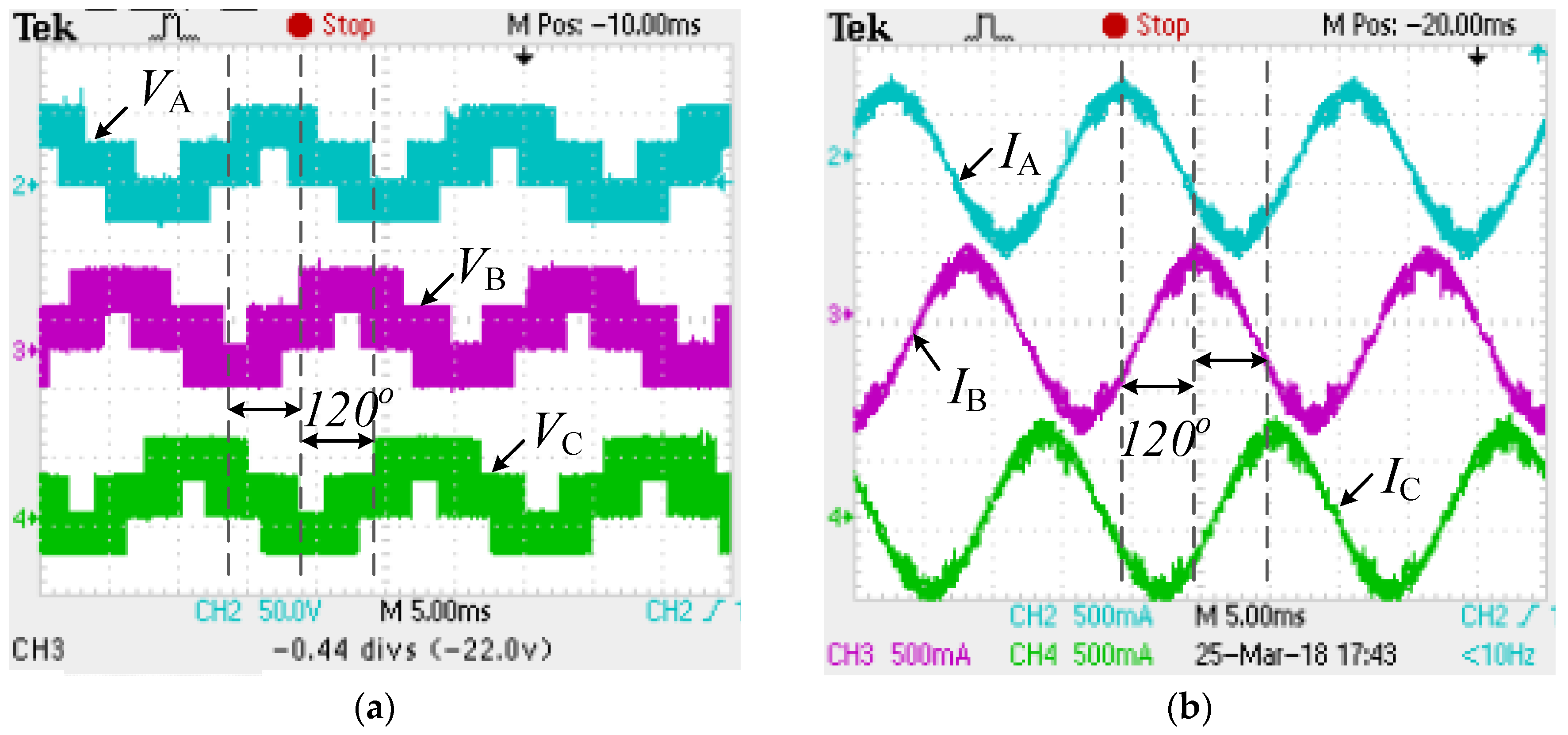
Figure 18 shows the output voltage and output current of three phases on steady state (60 Hz). Each phase of the inverter achieves multilevel working. The four voltage levels are −VDC, 0, VDC, 2VDC (with respect to the GND, the ground of the DC bus, rather than the center tap of the DC bus, VDC = 30 V).
4.3. Acceleration and braking mode
For better presentation of the waveforms sampled by the oscilloscope, the acceleration mode, and the braking mode are tested between 5 Hz and 10 Hz.
Figure 19a shows the output current of three phase on acceleration mode. With current close loop based on DQ transform, the amplitude of the current remains constant, only the frequency changes from 5 Hz to 10 Hz. Figure 19b shows the output current of three phase on braking mode. With current close loop based on DQ transform, the amplitude of the current remains constant, only the frequency changes from 10 Hz to 5 Hz. The instantaneous instruction of braking is a sudden change of frequency, however, the rotation rate of motor cannot be changed immediately, excessive speed causes transient current overflow on each phase. Extra power is transferred to the battery through the three phase inverter topology.
An interface software is compiled to communicate with the control unit (consists of a DSP: Digital Signal Processing and a CPLD: Complex Programmable Logic Device), instructions are sent to the control unit, while sample data and logic values are sent back to PC side. Figure 20 shows the whole process of the control presented by this software.
First, in the V/f start-up process, the HFL start working in state 1 and state 2, after state 2 PI controller is working to balance the DC bus voltage at 30 V, and the inverter start working in state 3. While the motor works on low speed condition, an acceleration instruction is made, and the motor begins to speed up with V/f method, the rotation increases with the increase of the amplitude of reference voltage, while the output current remains constant. While the motor works on the high speed condition, a braking instruction is made, a sudden decrease is obtained through braking method, and a current overflow occurs in that time.
4.4. Harmonic Analysis
HFL is used to create several isolated DC sources for the system, and on steady state, the DC voltage on each phase is balanced and identical. Thus, the HFL will not introduce harmonics in the output of the inverter. The harmonics are mainly caused by the cascaded low-frequency H-bridges, where the switching frequency is 5 kHz.
As shown in Figure 21, the half-bridge of the three-phase inverter introduces harmonics at 5 kHz and its multiples, which is the switching frequency. As for the CHB, the phase difference between the switching signals on the left arm and the right arm is half period (the switching frequency of each arm is 5 kHz). While the output voltage is the difference between the potential on the middle point, as a result, the harmonic frequency of the H-bridge is doubled. Thus, the main harmonics of phase A are at 5 kHz and 10 kHz. A mathematic analysis on harmonics of the H-bridge is given, as following.
Supposing that the pulse width of the left arm and right arm of the H-bridge is xL and xR, the range of which is [0, 2]. Using triangular carrier for modulation, then vb can be expressed, as below
where is the angular frequency of the carrier, k is an integer. In [], vb can be expressed as following
where
vb can be simplified as
vc is calculated in the same way
Then, the output of the H-bridge is obtained
The forward component denotes the effect of the reference waveform, and the backward component denotes the harmonics. As the phase difference between the two arms is half period, which means that the reference waveform is symmetrical through t-axis, as shown in Figure 21, thus . As
From (28) and (29), if n = 1, 2, 3, …, 2k + 1, vH is zero.
Thus, the lowest order harmonic of the CHB is at 10 kHz.
Figure 22 shows the experimental result of Fast Fourier Transformation (FFT) spectrum through oscilloscope, which is coincident with the analysis above.
4.5. Efficiency Analysis
Measurement of the efficiency is based on 60 Hz working state. The number of levels and efficiency changes with the amplitude of the reference output voltage.
As shown in Figure 23, the output voltage is based on two levels when the amplitude of the reference voltage is smaller than 0.5 VDC (only three phase inverter works in this mode), and it is based on four levels when the amplitude of the reference voltage is larger than 0.5 VDC, and smaller than the limit of 1.5 VDC (CHB works in this mode). The THD decreases with the increase of the levels, as a result the efficiency increases. With four levels, the efficiency is nearly above 90%, while larger reference voltage also benefits on each voltage level. There is a significant improvement of efficiency with four levels, and with more CHB, the efficiency can be improved further more.
5. Comparison with Relevant Works
CHB topology is widely used for implementing large-scale converters in power electronic applications due to its improved output waveforms. However, some challenges still exist. One is the isolation of the cascaded cells. Leakage currents can cause safety issues and additional losses, thus a large number of well isolated DC sources are needed in implementation. Another challenge is the voltage imbalance. One common method is to inject a zero-sequence voltage the exchange any excess energy between phase legs. However the voltage rating is increased. A new connection on converter topology is proposed in [27], by extending the function of dc-dc converters for photovoltaic (PV) applications. To solve the voltage imbalance, DC cells on different phases are connected in specific order. However, the imbalance of cells in the same phase is not solved. Though high efficiency is achieved through transformer-less connection, large number of isolated DC sources (PV arrays) are needed to guarantee the isolation. It is not feasible in vehicles where normally only one DC source (DC 144V) is available. On the contrary, a transformer with one magnetic core and multi windings is adopted to create several DC voltages with only one input source. Though magnetic loss is introduced, the power density is improved. As power conversion is allowed between all of the CHBs through the same transformer, it allows for balancing the voltage of cells both on same phase and different phases. Besides, isolation between cells is achieved as the power conversion is through coupling coil.
Three-phase switched reluctance (SR) motor drives with integrated charging functions are proposed in [28,29]. Less active switches are adopted in [28], and a three-phase rectifier is used to connect with the internal combustion engine (ICE) generator and the grid. Though it allows for bidirectional power conversion between the motor and the battery, the power from the ICE or the grid is unidirectional. While braking, the motor will charges the battery to regenerate the energy. As this energy cannot be transferred to the grid or the ICE due to the diode-rectifier, the voltage of the battery goes up which is bad for its life. An integrated multilevel converter of switched reluctance motors (SRMs) that were fed by a modular front-end circuit for plug-in hybrid electric vehicle (PHEV) applications. Due to the single-stage structure, the voltage stress of the active switches is high, thus high-voltage IGBTs are applied, which then increases the cost. When comparing with these motor drives above, the proposed converter combines dual-active bridge (DAB) and CHB configuration to realize higher multilevel output, and the DC voltage on each power cell is lowered. Thus, low-voltage MOSFETs are adopted to decrease the cost. To overcome the difficulties of isolation sources and voltage imbalance and to improve the power density, HFL is adopted for power conversion. Besides, hybrid frequency is adopted to reduce the volume of the transformer and decrease the switching losses. Comparison details are shown in Table 7.
6. Conclusions
A cascaded multilevel inverter using only one DC source has been implemented and tested. To improve the output voltage with low-rating-voltage MOSFETs, the multilevel theory, HFL, and CHB are combined. The HFL is made up of a multi-winding transformer and several H-bridges, where each phase is connected in the DAB configuration. It works in high-frequency mode, so as to reduce the cost and the size, also improve the power density. The corresponding control algorithm is proposed on the CHB inverter to output the multilevel voltage on each phase. Four-level output waveform is realized, and it can increase with the number of the CHB. Phase-shift control logic is adopted in the DAB configuration of the HFL side to balance the voltage of each power cell. Hybrid frequencies are utilized in the HFL side and CHB motor drive for multiple purpose. High-frequency in the HFL is to reduce the size and improve the power density, while low-frequency in the CHB motor drive is to reduce the switching loss. A magnetic biasing suppression method is proposed in order to eliminate the magnetic saturation. The theoretical analysis shows that about 64% of the power is delivered by the HFL. The proposed solution is capable to drive the 220 V or higher devices with only one 144 V DC power. An experimental prototype is established to verify the topology, and it will be installed on an electric vehicle to drive the squirrel-cage induction motor. Bidirectional power flow ability is tested, and extra energy can be regenerated and transferred to the input source. The less order output harmonics from the switching frequency on the low-frequency CHB are analyzed. The efficiency of the converter is higher than 90%, which increases with the levels of output. All of the H-bridges have the same parameters thus they are easy to be replaced and maintained. More ever, by simply increasing the number of H-bridges, the topology can also be used in other higher voltage applications to reduce the cost, where usually IGBTs are widely used before.
Author Contributions
Z.G. put forward the main idea, designed the topology and carried out the simulation. C.Z. verified the control algorithm, performed the experiments, collected the data and prepared some sections of the manuscript.
Funding
This work is supported by the National Science Foundation of China under Project 51777011.
Conflicts of Interest
The authors declare no conflict of interest.
References
- Wu, H.; Pang, G.K.H.; Choy, K.L.; Lam, H.Y. An Optimization Model for Electric Vehicle Battery Charging at a Battery Swapping Station. IEEE Trans. Veh. Technol. 2018, 67, 881–895. [Google Scholar] [CrossRef]
- Kaliamoorthy, M.; Rajasekaran, V.; Raj, I.G.C.; Raj, L.H.T. Generalised hybrid switching topology for a single-phase modular multilevel inverter. IET Power Electron. 2014, 7, 2472–2485. [Google Scholar] [CrossRef]
- Chattopadhyay, S.K.; Chakraborty, C. A New Asymmetric Multilevel Inverter Topology Suitable for Solar PV Applications with Varying Irradiance. IEEE Trans. Sustain. Energy 2017, 8, 1496–1506. [Google Scholar] [CrossRef]
- Xu, R.; Yu, Y.; Yang, R.; Wang, G.; Xu, D.; Li, B.; Sui, S. A Novel Control Method for Transformerless H-Bridge Cascaded STATCOM with Star Configuration. IEEE Trans. Power Electron. 2015, 30, 1189–1202. [Google Scholar] [CrossRef]
- Zhang, Y.; Wu, X.; Yuan, X. A Simplified Branch and Bound Approach for Model Predictive Control of Multilevel Cascaded H-Bridge STATCOM. IEEE Trans. Ind. Electron. 2017, 64, 7634–7644. [Google Scholar] [CrossRef]
- Busarello, T.D.C.; Mortezaei, A.; Paredes, H.K.M.; Al-Durra, A.; Pomilio, J.A.; Simões, M.G. Simplified Small-Signal Model for Output Voltage Control of Asymmetric Cascaded H-Bridge Multilevel Inverter. IEEE Trans. Power Electron. 2018, 33, 3509–3519. [Google Scholar] [CrossRef]
- Gadalla, A.S.; Yan, X.; Altahir, S.Y.; Hasabelrasul, H. Evaluating the capacity of power and energy balance for cascaded H-bridge multilevel inverter using different PWM techniques. IET J. Eng. 2017, 2017, 1713–1718. [Google Scholar] [CrossRef]
- Mukundan, C.M.N.; Jayapraksh, P. Solar PV fed cascaded H-bridge multilevel inverter and SIMO-SEPIC based MPPT controller for 3-phase grid connected system with power quality improvement. In Proceedings of the 2017 National Power Electrionics Conference (NPEC 2017), Pune, India, 18–20 December 2017; pp. 106–111. [Google Scholar]
- Li, Y.; Wang, Y.; Wang, R.; Wu, J.; Zhang, H.; Feng, Y.; Li, S.; Yao, W.; Li, B. Distributed Generation Grid-Connected Converter Testing Device Based on Cascaded H-Bridge Topology. IEEE Trans. Ind. Electron. 2016, 63, 2143–2154. [Google Scholar] [CrossRef]
- Rahman, M.A.; Islam, M.R. Modified High Frequency Phase Disposition Pulse Width Modulation for Modular Cascaded H-bridge Multilevel Converters. In Proceeding of the 2017 3rd International Conference on Electrical Information and Communication Technology (EICT 2017), Khulna, Bangladesh, 7–9 December 2017; pp. 1–5. [Google Scholar]
- Iyer, K.V.; Baranwal, R.; Mohan, N. A High-Frequency AC-Link Single-Stage Asymmetrical Multilevel Converter for Grid Integration of Renewable Energy Systems. IEEE Trans. Power Electron. 2017, 32, 5087–5108. [Google Scholar] [CrossRef]
- Zhao, B.; Song, Q.; Li, J.; Wang, Y.; Liu, W. Modular Multilevel High-Frequency-Link DC Transformer Based on Dual Active Phase-Shift Principle for Medium-Voltage DC Power Distribution Application. IEEE Trans. Power Electron. 2017, 32, 1779–1791. [Google Scholar] [CrossRef]
- Nair R, V.; Gopakumar, K.; Franquelo, L.G. A Very High Resolution Stacked Multilevel Inverter Topology for Adjustable Speed Drives. IEEE Trans. Ind. Electron. 2018, 65, 2049–2056. [Google Scholar]
- Haque, A.R.; Leng, S.; Salmon, J. Smart Electrical Grid Interface Using Floating H-Bridges to Improve the Performance of Induction Motors. IEEE Trans. Power Electron. 2017, 32, 7851–7861. [Google Scholar] [CrossRef]
- Moosavi, M.; Farivar, G.; Iman-Eini, H.; Shekarabi, S.M. A Voltage Balancing Strategy with Extended Operating Region for Cascaded H-Bridge Converters. IEEE Trans. Power Electron. 2014, 29, 5044–5053. [Google Scholar] [CrossRef]
- Moeini, A.; Iman-Eini, H.; Marzoughi, A. DC link voltage balancing approach for cascaded H-bridge active rectifier based on selective harmonic elimination-pulse width modulation. IET Power Electron. 2015, 8, 583–590. [Google Scholar] [CrossRef]
- Lezana, P.; Aceitón, R.; Silva, C. Phase-Disposition PWM Implementation for a Hybrid Multicell Converter. IEEE Trans. Ind. Electron. 2013, 60, 1936–1942. [Google Scholar] [CrossRef]
- Masaoud, A.; Ping, H.W.; Mekhilef, S.; Taallah, A. Novel configuration for multilevel DC-link three-phase five-level inverter. IET Power Electron. 2014, 7, 3052–3061. [Google Scholar] [CrossRef]
- Prabaharan, N.; Palanisamy, K. Analysis of cascaded H-bridge multilevel inverter configuration with double level circuit. IET Power Electron. 2017, 10, 1023–1033. [Google Scholar] [CrossRef]
- Vasiladiotis, M.; Rufer, A. A Modular Multiport Power Electronic Transformer with Integrated Split Battery Energy Storage for Versatile Ultrafast EV Charging Stations. IEEE Trans. Ind. Electron. 2015, 62, 3213–3222. [Google Scholar] [CrossRef]
- Jung, J.; Lee, J.; Sul, S.; Son, G.; Chung, Y. DC Capacitor Voltage Balancing Control for Delta-Connected Cascaded H-Bridge STATCOM Considering Unbalanced Grid and Load Conditions. IEEE Trans. Power Electron. 2018, 33, 4726–4735. [Google Scholar] [CrossRef]
- Hasan, M.M.; Abu-Siada, A.; Islam, M.R. Design and implementation of a novel three-phase cascaded half-bridge inverter. IET Power Electron. 2016, 9, 1741–1752. [Google Scholar] [CrossRef]
- Sha, D.; Xu, G.; Xu, Y. Utility Direct Interfaced Charger/Discharger Employing Unified Voltage Balance Control for Cascaded H-Bridge Units and Decentralized Control for CF-DAB Modules. IEEE Trans. Ind. Electron. 2017, 64, 7831–7841. [Google Scholar] [CrossRef]
- Nair R, V.; Rahul S, A.; Kaarthik, R.S.; Kshirsagar, A.; Gopakumar, K. Generation of Higher Number of Voltage Levels by Stacking Inverters of Lower Multilevel Structures With Low Voltage Devices for Drives. IEEE Trans. Power Electron. 2017, 32, 52–59. [Google Scholar]
- Iman-Eini, H.; Bacha, S.; Frey, D. Improved control algorithm for grid-connected cascaded H-bridge photovoltaic inverters under asymmetric operating conditions. IET Power Electron. 2018, 11, 407–415. [Google Scholar] [CrossRef]
- Pereda, J.; Dixon, J. High-Frequency Link: A Solution for Using Only One DC Source in Asymmetric Cascaded Multilevel Inverters. IEEE Trans. Ind. Electron. 2011, 58, 3884–3892. [Google Scholar] [CrossRef]
- Townsend, C.D.; Yu, Y.; Konstantinou, G.; Agelidis, V.G. Cascaded H-Bridge Multilevel PV Topology for Alleviation of Per-Phase Power Imbalances and Reduction of Second Harmonic Voltage Ripple. IEEE Trans. Power Electron. 2016, 31, 5574–5586. [Google Scholar] [CrossRef]
- Hu, Y.; Song, X.; Cao, W.; Ji, B. New SR Drive With Integrated Charging Capacity for Plug-In Hybrid Electric Vehicles (PHEVs). IEEE Trans. Ind. Electron. 2014, 61, 5722–5731. [Google Scholar] [CrossRef] [Green Version]
- Gan, C.; Wu, J.; Hu, Y.; Yang, S.; Cao, W.; Guerrero, J.M. New Integrated Multilevel Converter for Switched Reluctance Motor Drives in Plug-in Hybrid Electric Vehicles With Flexible Energy Conversion. IEEE Trans. Power Electron. 2017, 32, 3754–3766. [Google Scholar] [CrossRef] [Green Version]
Figure 1.
Proposed CHB inverter with high-frequency link using only one DC source.

Figure 2.
Modulation method for the proposed topology.

Figure 3.
Generation of the gate signals: (a) |vref| < 0.5VDC; and, (b) |vref| ≥ 0.5VDC.
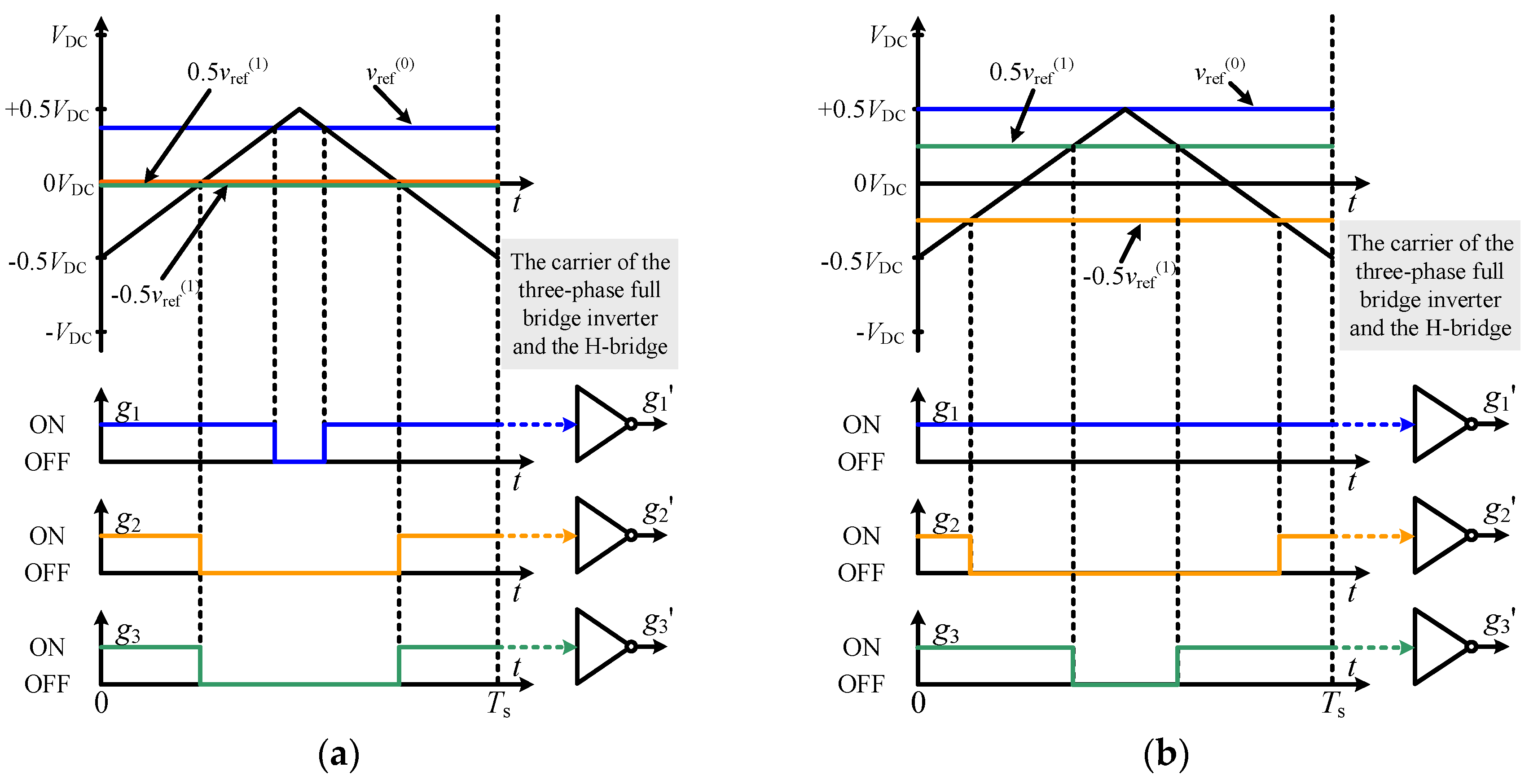
Figure 4.
Reference voltages and three-phase currents (simulation).
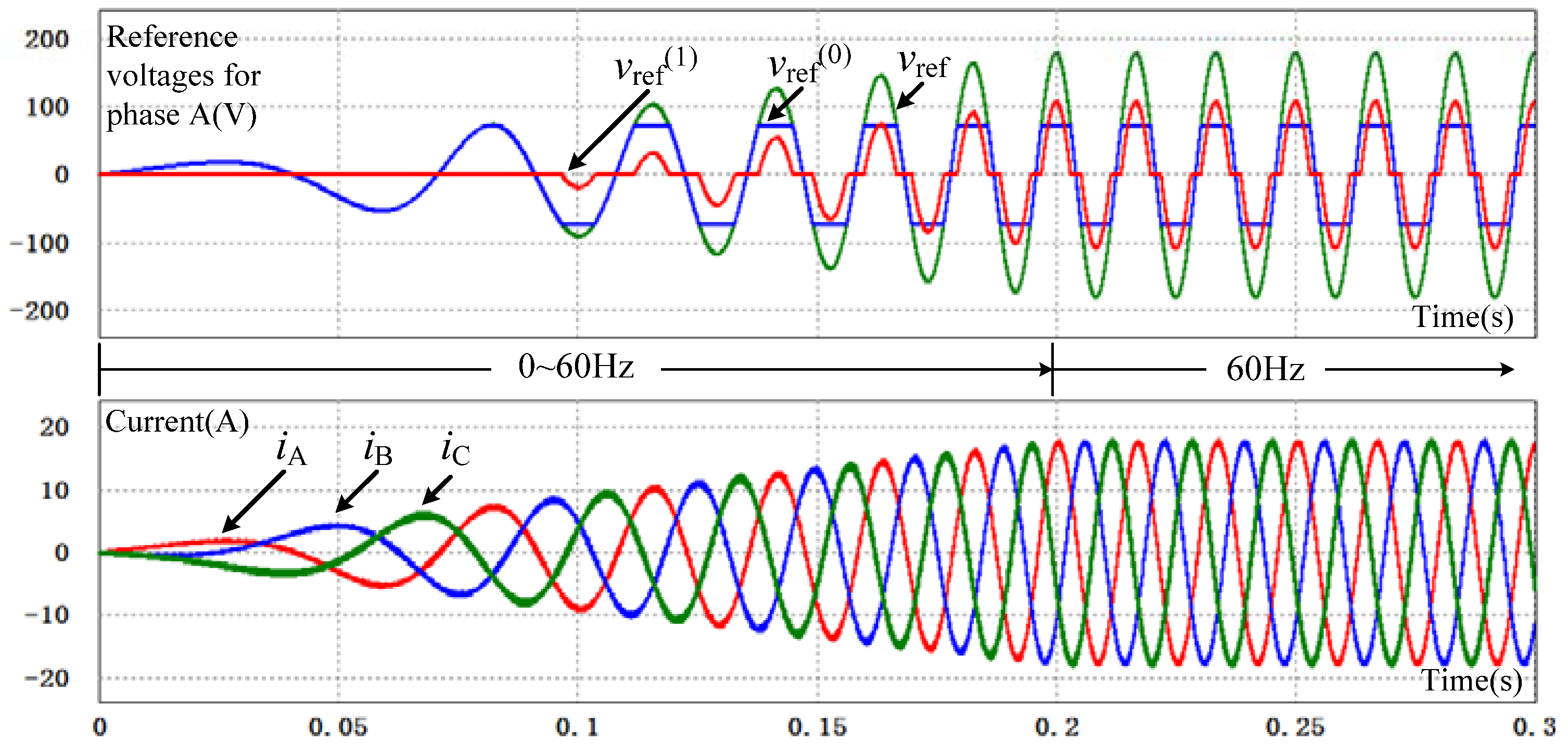
Figure 5.
Three-phase output voltages (simulation).

Figure 6.
Waveforms of vref, equivalent voltage and current.
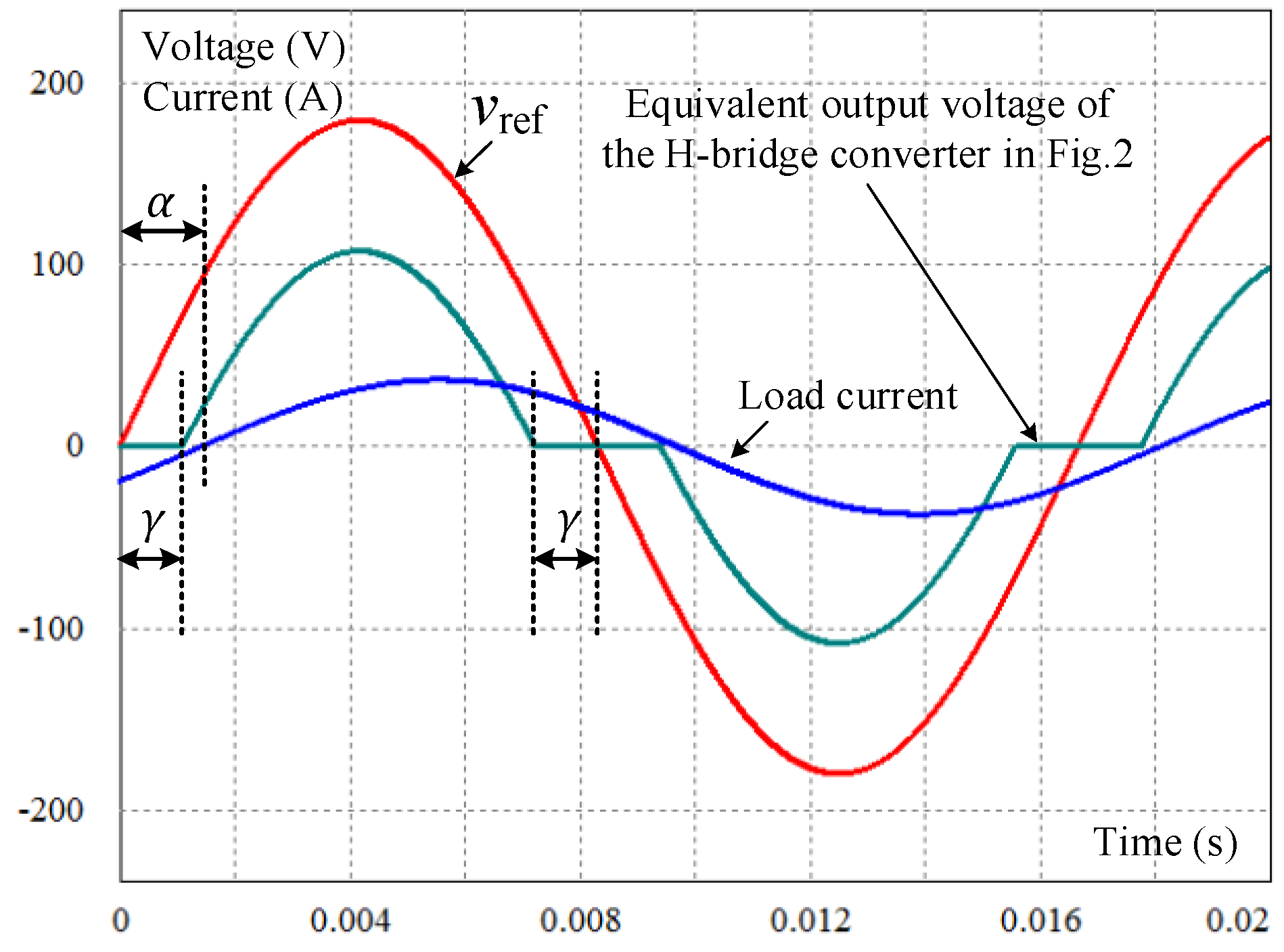
Figure 7.
Curves of P1* in different cases.
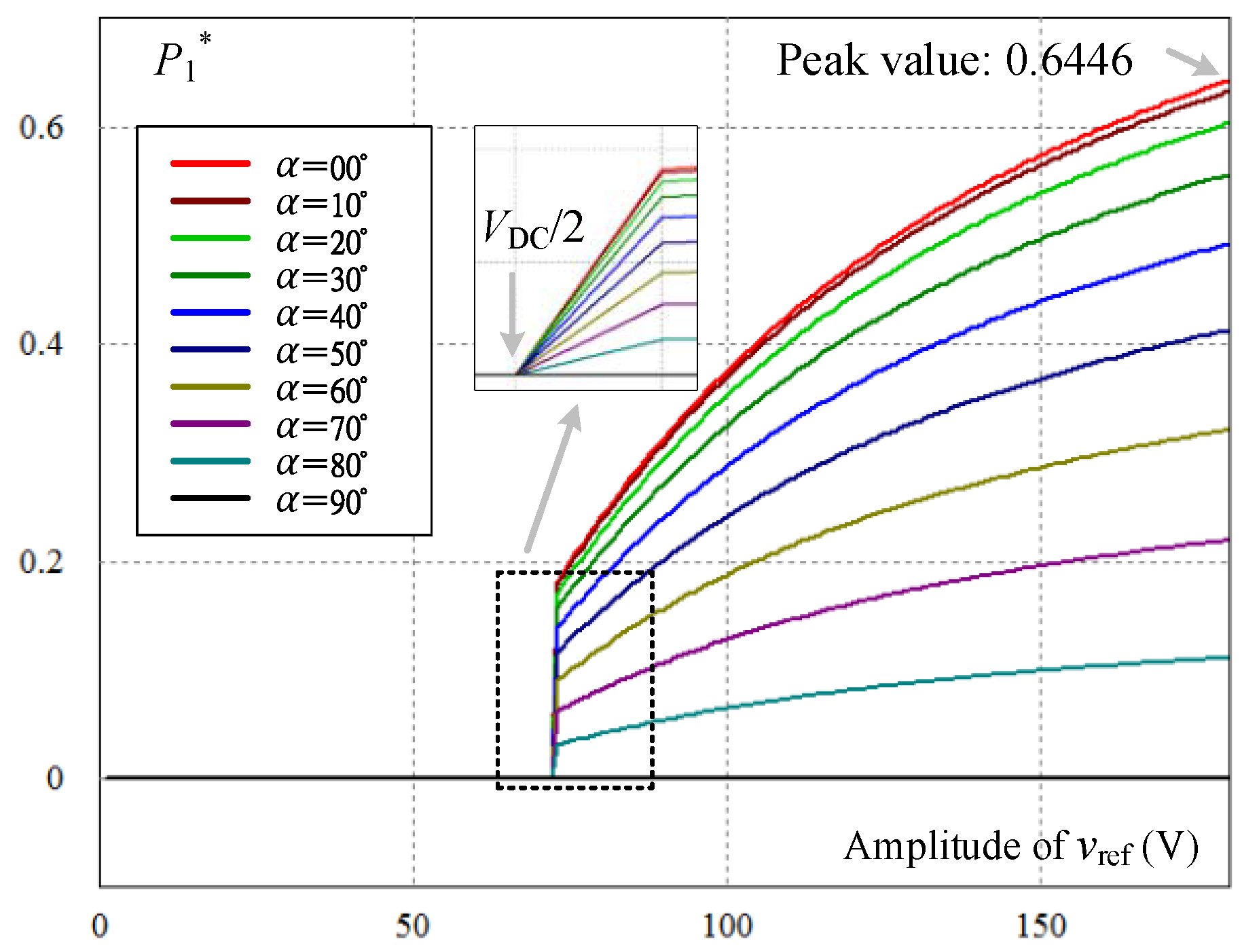
Figure 8.
Flux and voltage in the HF transformer.

Figure 9.
Equivalent circuit of the HF transformer.
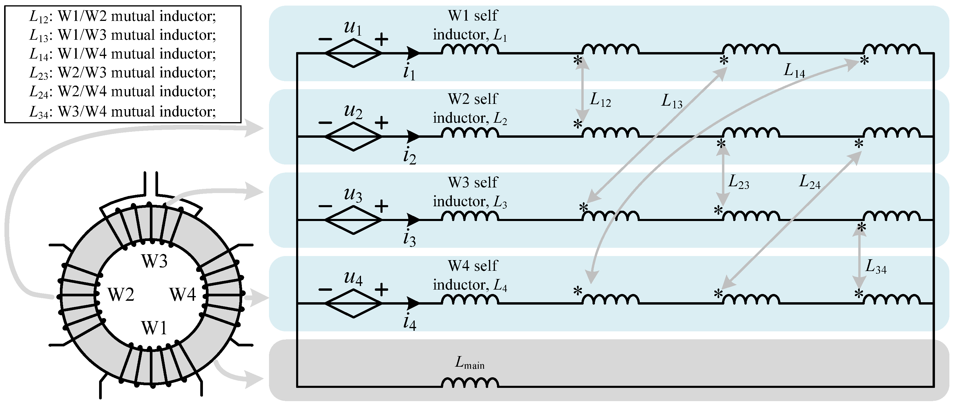
Figure 10.
Simplified equivalent circuit of HF transformer.

Figure 11.
Power flow model of VDC–k.
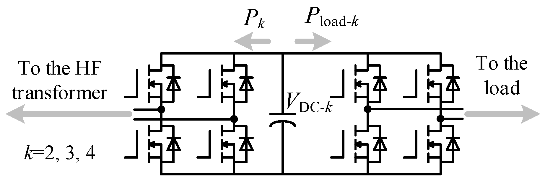
Figure 12.
Control diagram of VDC–2~VDC–4.

Figure 13.
Magnetic biasing suppression diagram.

Figure 14.
Performance of magnetic current: (a) Magnetic biasing phenomenon; and, (b) Experimental results with magnetic biasing suppression method.
Figure 14.
Performance of magnetic current: (a) Magnetic biasing phenomenon; and, (b) Experimental results with magnetic biasing suppression method.

Figure 15.
Experimental prototype of the proposed multilevel inverter.

Figure 16.
DC bus voltage on each phase.
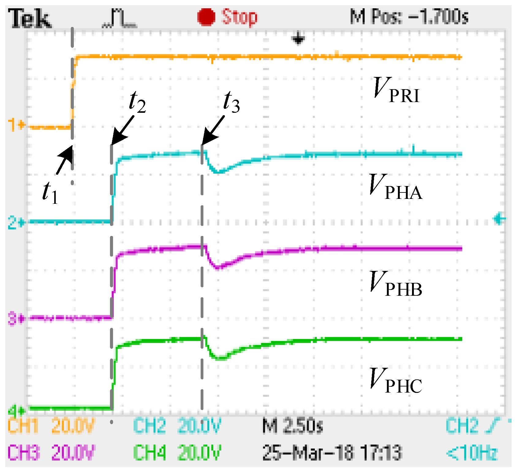
Figure 17.
Three phase current in V/f start-up period.

Figure 18.
Output waveforms of three phases on steady state: (a) voltage waveforms; and, (b) current waveforms.
Figure 18.
Output waveforms of three phases on steady state: (a) voltage waveforms; and, (b) current waveforms.

Figure 19.
Output current of three phases: (a) on acceleration mode; and, (b) on braking mode.
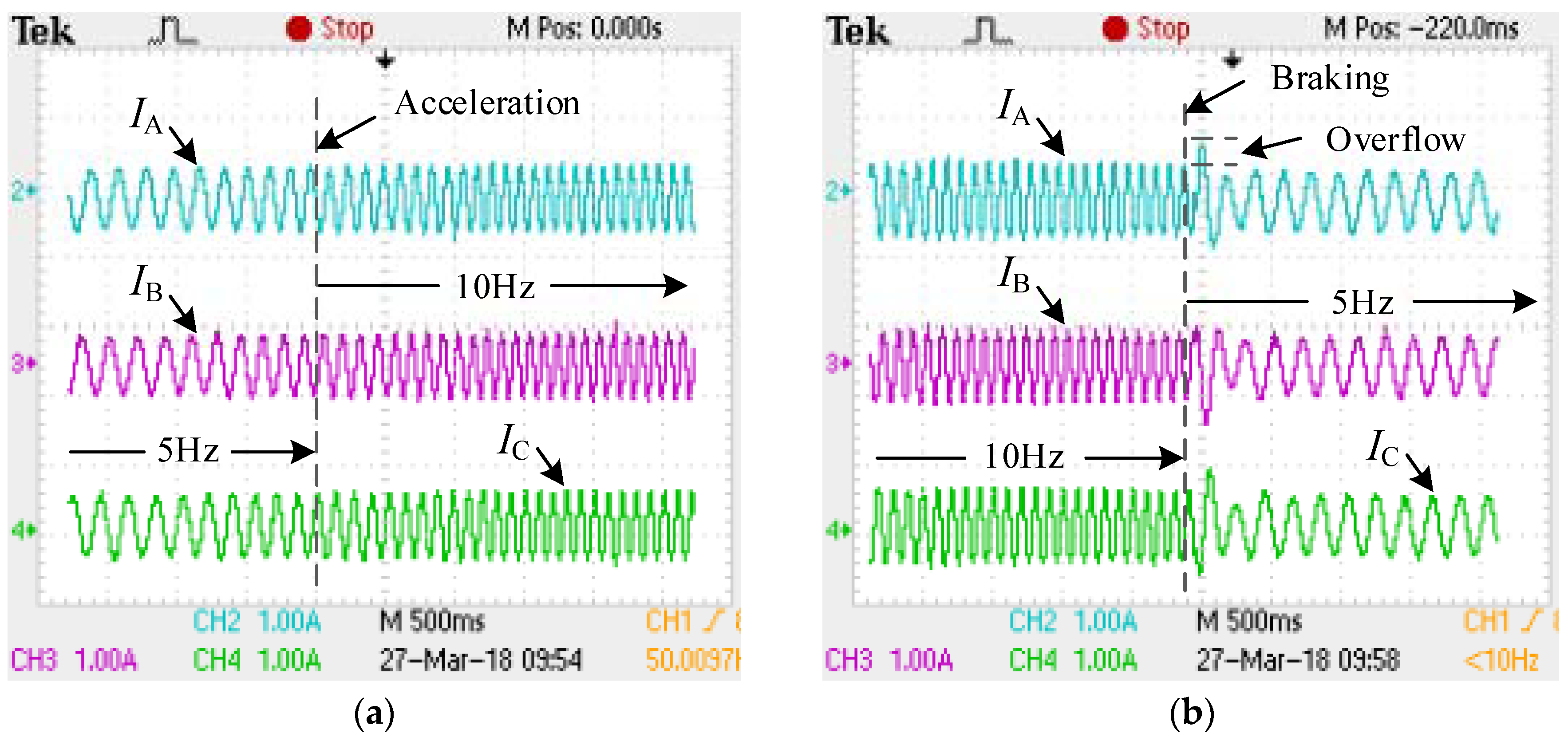
Figure 20.
The whole process of the control.

Figure 21.
Harmonic analysis on the cascaded low-frequency H-bridges of phase A.
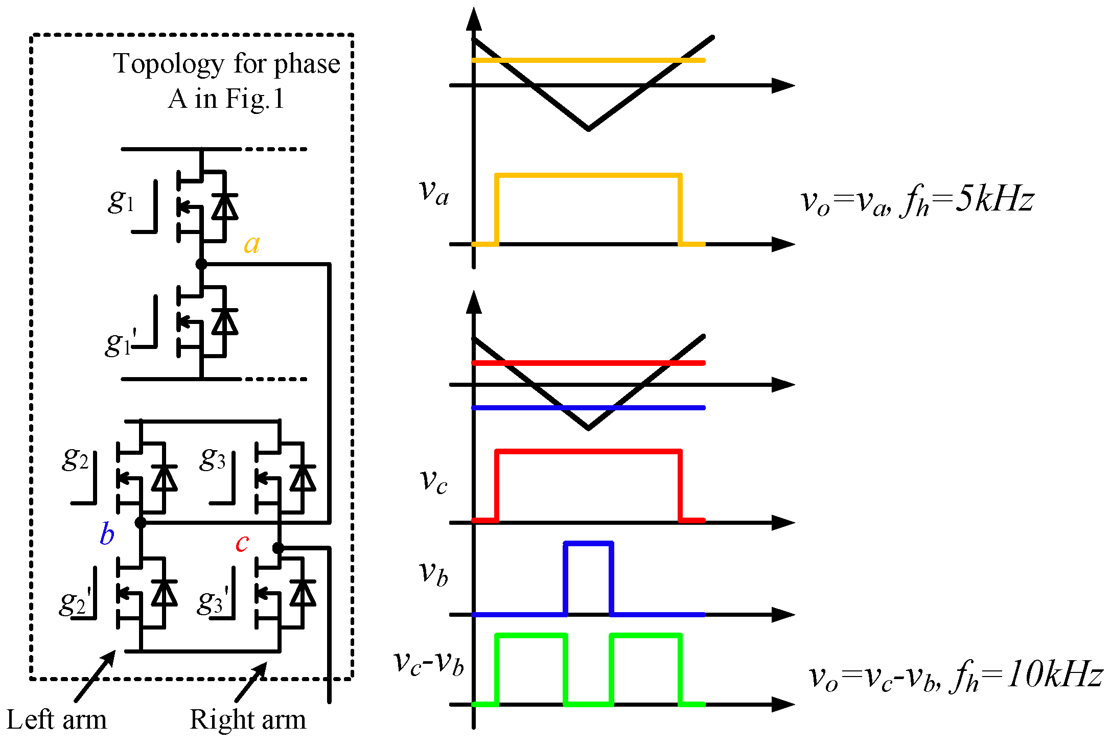
Figure 22.
FFT spectrum of the multilevel output voltage through oscilloscope.

Figure 23.
Experimental efficiency on different reference voltage.


Table 1.
Applications of the proposed inverter.
| Applications | Characteristics |
|---|---|
| Electric vehicles | The on-car battery voltage is low and cannot power the devices such as iceboxes and microwave ovens directly. |
| Backup power supplies | Batteries are used to storage the energy. High AC voltages are required. |
| High gain DC/AC converters | Connections from low DC voltage to high AC voltages. |
| Micro grids with DC buses | DC bus voltage is not high enough for AC devices. |
Table 2.
Simulation parameters.
| Item | Characteristics |
|---|---|
| DC bus voltage, VDC | 144 V |
| Number of H-bridges, N | 1 |
| Switching period, Ts | 0.2 ms |
| Three-phase load, ZA = ZB = ZC | 10 + 1.885j Ω, Y type |
| Voltage/Frequency | 179.6 (V)/60 (Hz) |
Table 3.
Winding parameters.
| Windings | Power | Voltage | Current |
|---|---|---|---|
| W1 | 6.5 kW 1 | 144 V | 45 A |
| W2 | 6.5/3 kW | 144 V | 15 A |
| W3 | 6.5/3 kW | 144 V | 15 A |
| W4 | 6.5/3 kW | 144 V | 15 A |
1 The maximal power flowing through the HF transformer can be calculated in Figure 7.
Table 4.
Experimental parameters.
| Item | Value |
|---|---|
| DC bus voltage, VDC | 5 V |
| Magnetic core area | 324 mm2 |
| Magnetic core material | Ferrite |
| W1 number of turns | 19 |
| HF voltage period | 25 us |
| HF voltage positive time span | 13 us |
| HF voltage negative time span | 12 us |
| Dead band | 3 us |
Table 5.
Motor parameters.
| Item | Value |
|---|---|
| Three phase voltage | 220/380 V |
| Frequency | 60 Hz |
| Rated power | 50 W |
| Rotation rate | 3600 r/min |
Table 6.
Cost list.
| Component | Type | Cost ($) |
|---|---|---|
| MOSFET | IRF640N | 0.46 |
| Transformer | 1:1:1:1 | 15.4 |
| Capacitor | 6800 mF | 6.1 |
Table 7.
Comparison of relevant works.
| Item | Proposed Inverter | Inverter in [27] | Inverter in [28] | Inverter in [29] |
|---|---|---|---|---|
| Isolated sources | 1 | >9 | 1 | 1 |
| Isolation require | No need | Need | No need | No need |
| Voltage balance | All | Parts | No need | No need |
| Multilevel | Increase with number of CHB | Increase with number of CHB | Not realized | 2–3 |
| Harmonic loss | Low | Low | High | High |
| Size | Middle | Large | Small | Small |
| Cost | Low | Low | High | High |
| Modularity and Feasibility | High | High | Low | Low |
© 2018 by the authors. Licensee MDPI, Basel, Switzerland. This article is an open access article distributed under the terms and conditions of the Creative Commons Attribution (CC BY) license (http://creativecommons.org/licenses/by/4.0/).
Share and Cite
MDPI and ACS Style
Zhang, C.; Gao, Z. A Cascaded Multilevel Inverter Using Only One Battery with High-Frequency Link and Low-Rating-Voltage MOSFETs for Motor Drives in Electric Vehicles. Energies 2018, 11, 1778. https://doi.org/10.3390/en11071778
AMA Style
Zhang C, Gao Z. A Cascaded Multilevel Inverter Using Only One Battery with High-Frequency Link and Low-Rating-Voltage MOSFETs for Motor Drives in Electric Vehicles. Energies. 2018; 11(7):1778. https://doi.org/10.3390/en11071778
Chicago/Turabian StyleZhang, Chao, and Zhigang Gao. 2018. "A Cascaded Multilevel Inverter Using Only One Battery with High-Frequency Link and Low-Rating-Voltage MOSFETs for Motor Drives in Electric Vehicles" Energies 11, no. 7: 1778. https://doi.org/10.3390/en11071778
Note that from the first issue of 2016, this journal uses article numbers instead of page numbers. See further details here.