1. Introduction
With the increasing penetration of renewable energy sources (RESs), the microgrid, which is regarded as a promising approach to integrate various distributed generation resources with the power grid, is attracting more interest from scholars. However, the extensive use of electronic power converters poses new challenges to microgrid operation and control due to the significant decrease of system rotating inertia. The occurrence of power deficiency or shortage will result in large frequency fluctuation. Especially when the microgrid operates in islanded mode, system frequency stability is under great threat due to the intermittency and stochasticity of RESs and load demands. Therefore, in order to maintain the stability of system frequency, numerous energy storages are integrated with the microgrid, which also increase system cost and scale. Nevertheless, the plug-in electric vehicles can be regarded as mobile battery energy storages and provide a valuable contribution to frequency regulation. Considering the more complicated topological structure of the microgrid, it is of significant importance to design more effective control strategies to ensure the system frequency stability.
Traditionally, the centralized control strategy (CCS) has been widely employed to deal with the load frequency control (LFC) problem [
1,
2,
3]. However, the single-point failure of the central controller may break down the entire system. Furthermore, the implementation of CCS strongly depends on the computational capability of the central controller and the communication capability of the network. The CCS requires global information of each component of the microgrid. That is to say, in addition to the time delay caused by the calculation process, the communication delay is negligible. The significant time delay directly brings great challenges to the islanded microgrid in realizing rapid frequency regulation. In the past few years, many scholars have devoted themselves to improving system frequency stability by reducing negative the influences caused by communication and calculation time delays [
4,
5].
Different from CCS, the distributed control strategy (DCS) only requires information collected through a local communication network. It is more flexible and reliable in satisfying the requirements of the microgrid, especially a microgrid with a high penetration of renewable energy sources. Therefore, due to its excellent characteristics including high reliability and flexibility, low cost and high computational efficiency, DCS is more suitable to solve the LFC problem in the microgrid. Furthermore, the multi-agent system (MAS) is widely employed in the distributed control strategy [
6,
7,
8,
9,
10], and it is also adopted in this paper. Researchers have proposed various distributed control strategies based on MAS to maintain the frequency stability of the microgrid with plug-in electric vehicles. In [
11], a novel PEV charging model for frequency regulation was proposed to maximize PEVs’ total utility and to satisfy individual PEVs’ daily drive patterns simultaneously. A fully-distributed control scheme is proposed to economically share wind power fluctuations among multiple PEVs and realize flexible frequency regulation. In [
12], a distributed peer-to-peer multi-agent framework is proposed to maintain the supply-demand balance in the microgrid, and the PEVs are considered as destributed energy storages (DESs). In [
13], the proposed cooperative distributed control strategy for PEVs maximizes the welfare and satisfaction of PEV customers while considering the charging constraints. The frequency stability is well ensured in the aforementioned literature; however, it can be further improved by designing more efficient control strategies.
In fact, although the aggregates of PEVs can be regarded as a special kind of battery energy storage system, the output power of PEVs is stochastic and fluctuating. That is to say, it is almost impossible for PEVs to be controlled the same as the battery energy storage system to provide accurate performance. Therefore, a novel fully-distributed load frequency control strategy for the islanded microgrid with the contribution of plug-in electric vehicles is proposed in this paper. First of all, this paper designs local controllers for PEVs to eliminate frequency deviation. A new performance indicator named the controllable power rate (CPR) is proposed to coordinate the PEVs’ output power, and the CPR is calculated through consensus-based MAS. The advantages of this design in comparison to other works is as follows: The CPR is only used to dispatch the total power that needs to be adjusted, that is to say the communication time delay of CPR does not affect the control activity of local controllers. It can be obviously found that the negative effect of time delay is well avoided, and the frequency stability is greatly enhanced. This is also the major contribution of this paper. To the authors’ best knowledge, few studies have been carried out with the consideration of controlling the stochastic and fluctuating power of PEVs. Except the proposed CPR, this paper also employs an improved linear active disturbance rejection control (ILADRC) algorithm [
14] because of its excellent robustness and anti-disturbance capacity. The stochastic and fluctuating power of PEVs can be regarded as system external disturbance, then it can be estimated by the linear extended state observer and compensated by the well-designed control law. Finally, a two-layer parallel MAS framework consisting of a plug-in electric vehicle multi-agent system (PEV-MAS) and a diesel generator multi-agent system (DG-MAS) is designed to realize distributed control of the islanded microgrid. Under this system, the PEVs can operate at the maximum charging rate most of the time. The output power of PEVs only contributes to the frequency regulation process, and then, the changed power of PEVs will be compensated by the DGs. However, most of the previous works only considered the contribution of PEVs to frequency regulation and neglected people’s requirements of quick charging.
Numerical simulations are carried out to demonstrate the effectiveness of the proposed control strategy. The controller parameters are optimized by genetic algorithm-based particle swarm optimization (GA-based PSO). Simulations are based on the MATLAB/Simulink (R2017b, The MathWorks, Inc., Natick, MA, USA) environment.
The rest of this paper is organized as follows. The fundamental theories of the consensus algorithm and ILADRC algorithm are described in
Section 2. The dynamic models of the islanded microgrid are introduced in
Section 3. Then, the proposed control strategy is described in
Section 4.
Section 5 presents the simulation results and analysis. Finally, conclusions are drawn in
Section 6.
3. Simulation Model
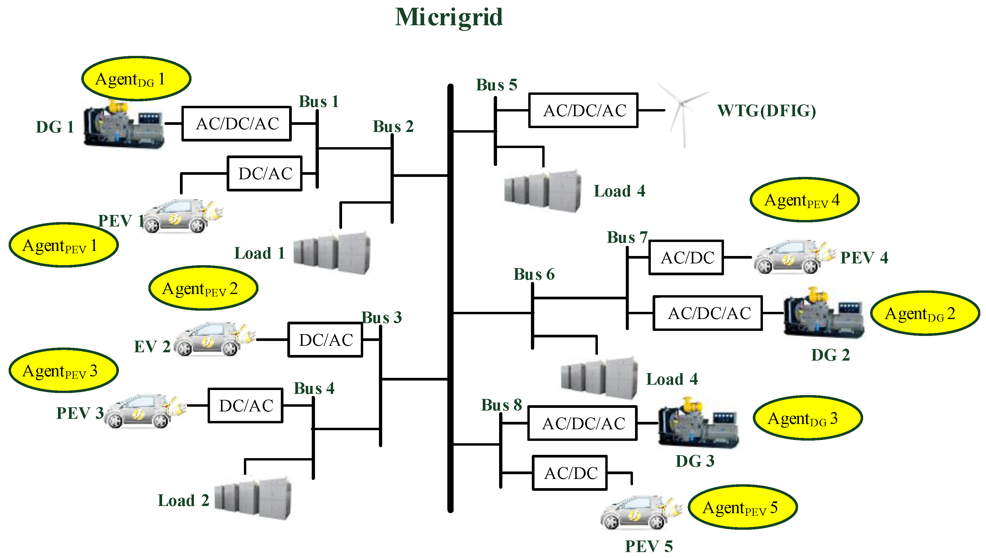
This paper considers the islanded microgrid with the combination of the diesel generator (DG), the variable-speed wind turbine generator (WTG), the plug-in electric vehicle (PEV) and load demand, where WTG and DG generate power for load consumption and the charging of the PEV. The configuration of the microgrid system is described in
Figure 1. Due to the rapid response of PEVs’ power output, the PEVs can be properly controlled to realize fast frequency recovery [
15]. Then, the total power change of PEVs is compensated by DGs. Meanwhile, the variable-speed WTG participates in frequency regulation by releasing the inertia and sharing the resultant energy with the grid following the grid frequency fluctuation.
In the stable system state, the output power of each component satisfies the following equation:
where
is the output power of WTG,
is the output power of DG,
is the output power of PEV and
is the load demand.
The balance of load demand and generated power determines the frequency stability. The frequency deviation can be calculated by Equation (
2) when the system power is out of balance. The deviation of the system power is calculated by Equation (
3). Furthermore, the delay of the frequency characteristics is considered for the actual practice. Hence, according to [
16], the Equation (
2) is transformed into Equation (
4):
where
and
denote the frequency deviation of the microgrid and the power deviation of the microgrid, respectively.
k denotes the microgrid frequency characteristic constant;
denotes the system transfer function;
M and
D are the equivalent inertia constant and damping constant of the microgrid, respectively. The values of the parameters are shown in
Table 1 [
17].
3.1. Diesel Generator Model
The diesel generator is an important component of the islanded microgrid power system, as it provides the main output power and compensates the system power deviation to ensure the stability of the microgrid power system. In this paper, a second-order lag transfer function model of DG is used for simulation, which can almost describe the actual model [
17]. The transfer function is described by Equation (
5), and parameter values are shown in
Table 1.
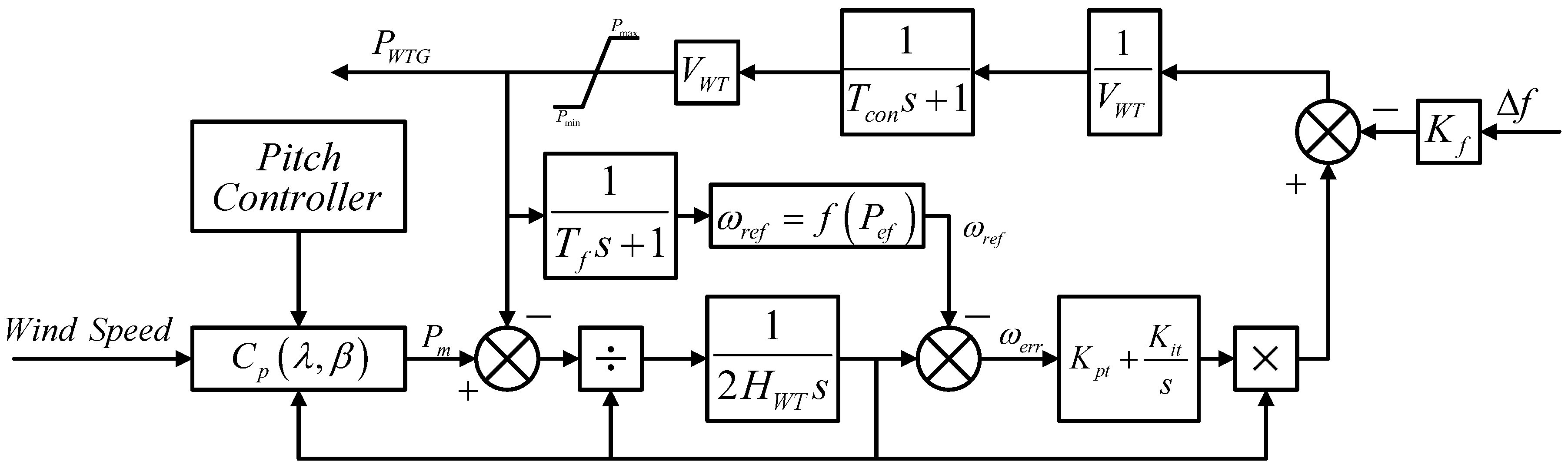
3.2. Variable-Speed Wind Turbine Generator Model
The rotation speed of the wind turbine generator is decoupled from the microgrid system frequency because of the extensive application of power electronic converters, which results in the mitigation of microgrid inertia [
18]. The microgrid system stability is greatly reduced due to the aforementioned situation. In order to make the WTG contribute to the frequency regulation, many effective control strategies based on variable-speed WTG have been proposed by researchers [
19], one of which is described in
Figure 2. The values of the parameters are shown in
Table 2.
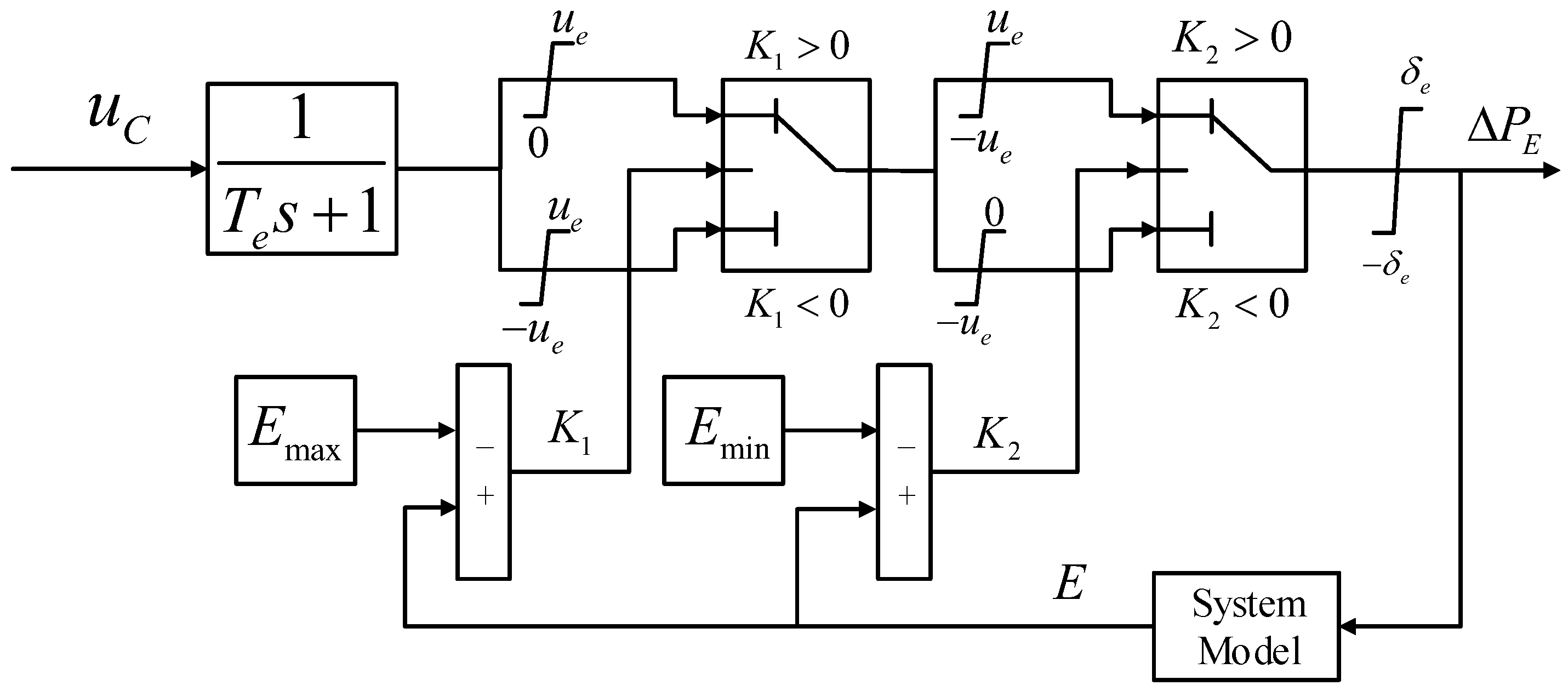
3.3. Plug-In Electric Vehicle Model
An equivalent PEV model is employed in this paper. Based on the charging and discharging characteristics, the equivalent PEV model can be divided into battery and charger [
20]. The model used for frequency regulation [
21] is described in
Figure 3, where
s is the time constant of PEV and
is the control signal from the PEV-agent.
is limited between
p.u. and
p.u.
E is the current charging or discharging power of the PEV.
and
are the maximum and minimum controllable energy of the PEV, respectively.
p.u. are the limits of the power ramp rate.
is the final output power of the PEV.
4. Proposed Distributed Control Strategy
Based on the aforementioned model in
Section 3, the proposed distributed control strategy is introduced in detail in this section.
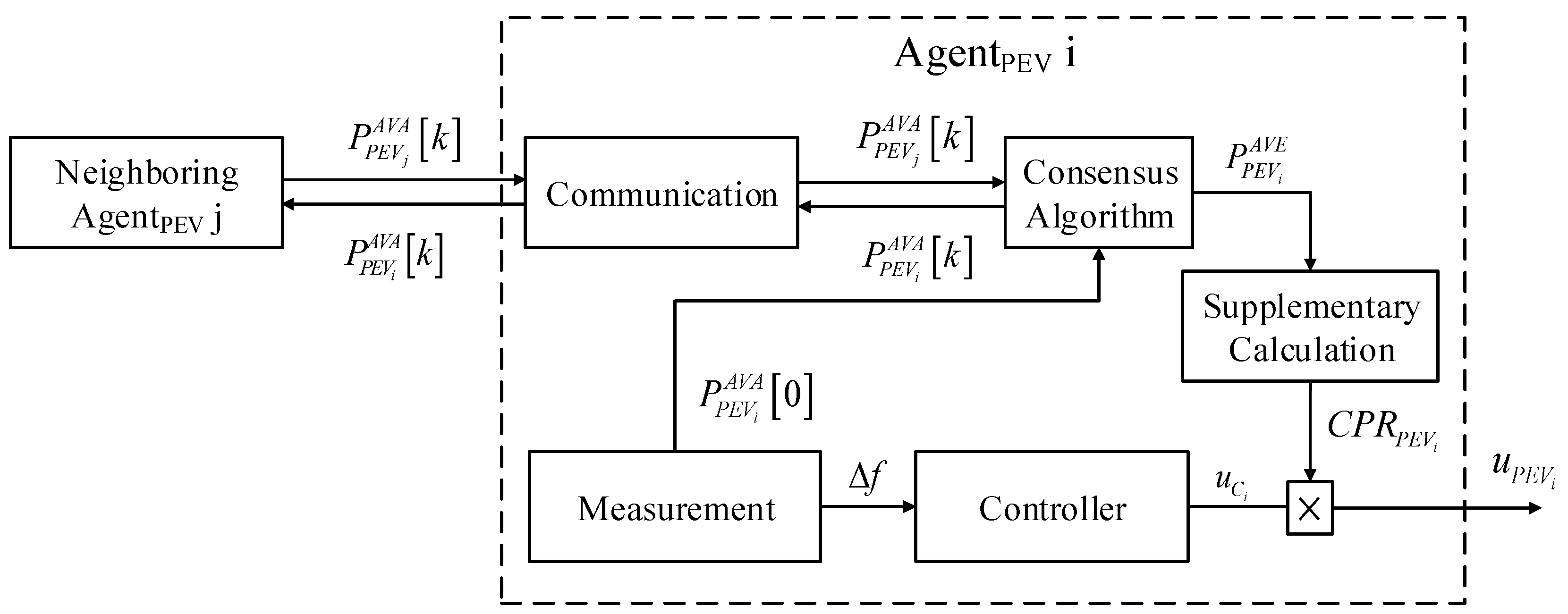
For the traditional microgrid, the energy storage system (ESS) mainly consists of battery energy storage, flywheel energy storage, and so on, which is usually placed centrally. Then, the power deficiency of the microgrid can be quickly compensated by ESS through the central controller. However, it is inappropriate for PEVs to be controlled by the central controller due to the decentralization of PEVs. The realization of communication among PEVs based on the central controller has a high cost. Moreover, the calculation and communication delay of the centralized control strategy adversely affects the rapid response characteristic of frequency regulation. Therefore, a novel distributed control strategy is proposed in this paper to ensure the frequency stability. This paper proposes a new performance indicator named the controllable power rate (CPR), and PEVs are controlled following the CPR calculated through consensus-based MAS. The CPR and local controllers of PEVs together protect the entire system from the negative effect caused by time delay, which is also the major advantage in comparison of other previous works. The system control construction in this paper is illustrated in
Figure 4.
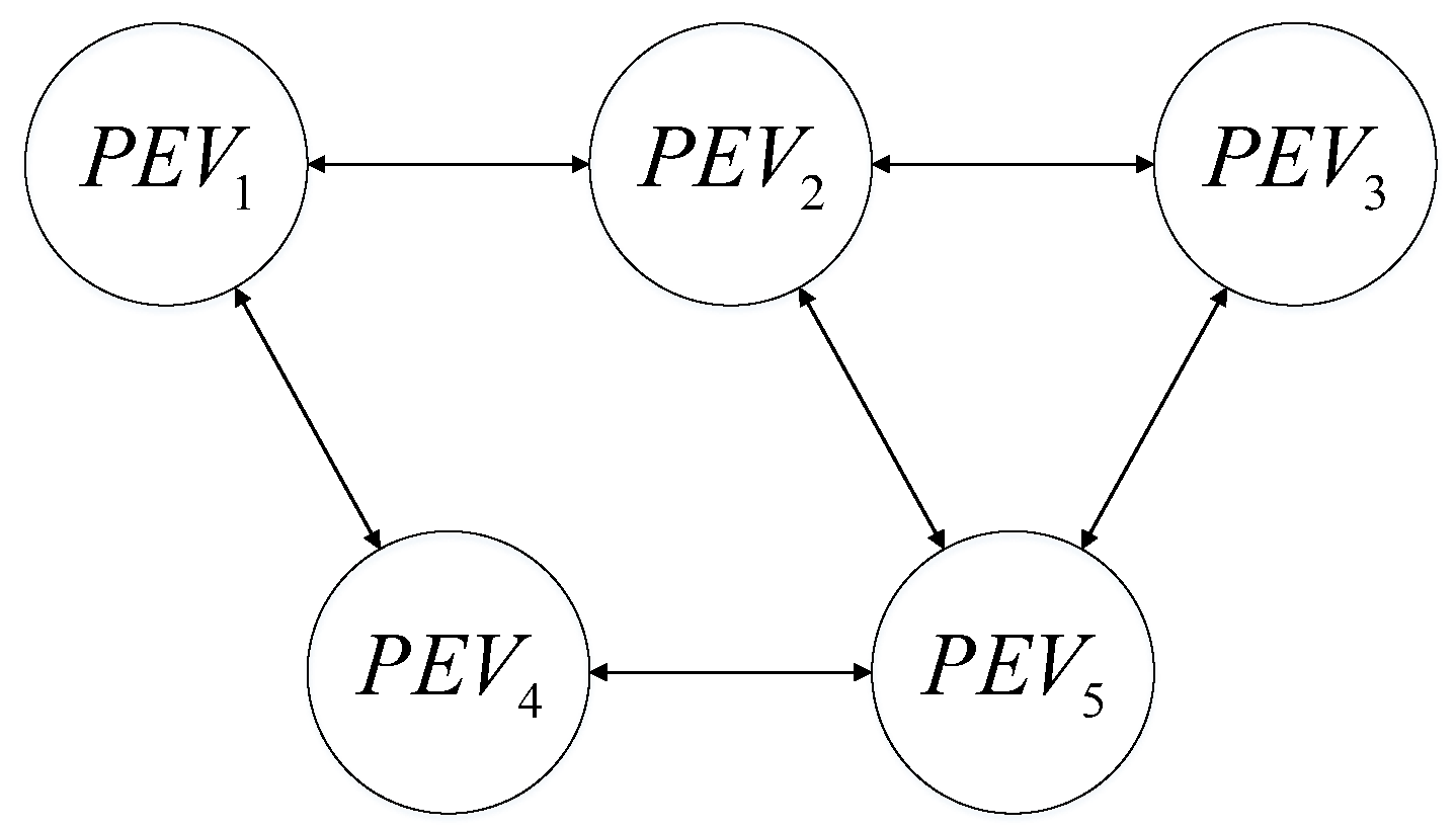
The PEVs are divided into five different units according to their distance, and each unit is managed by one PEV-agent. The frequency deviation can be measured locally, and it is eliminated by the ILADRC-based controller. However, there exists the universal phenomenon that one of the PEVs cannot provide enough power to eliminate the frequency derivation based on the average algorithm. Therefore, in this paper, the controllable power rate of the PEV is calculated through the consensus algorithm, which is described by Equations (15) and (16), and the control signal of each PEV unit follows Equation (
17). The communication topology of PEVs is described in
Figure 5.
where
denotes the average available power change of PEV,
denotes the available power change of
,
denotes the control signal of ILADRC-based controller and
denotes the final control signal of
.
Based on the aforementioned control strategy, the distributed control of PEVs is realized without the negative effects caused by calculation and communication delay.
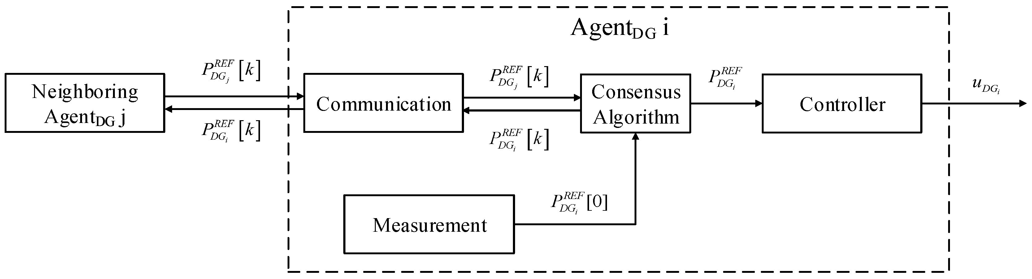
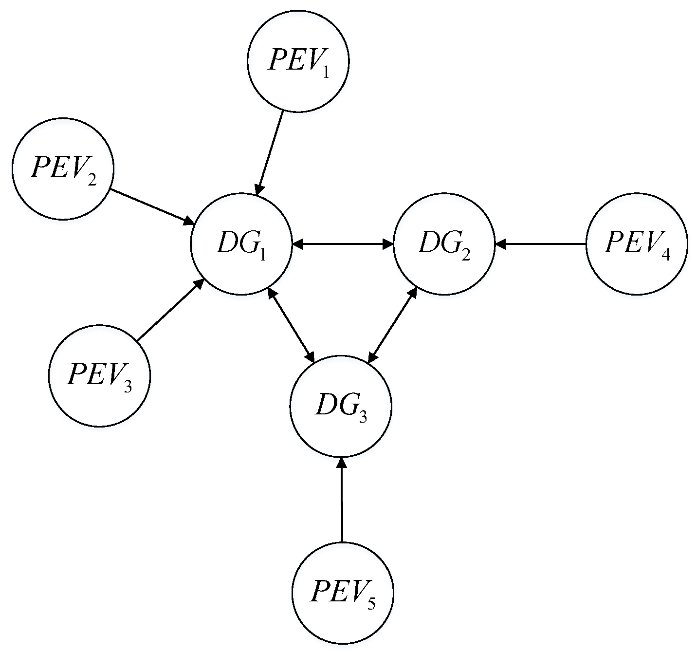
The agent and control structures of DG are illustrated in
Figure 6. The total variable power of PEVs is regarded as the total reference power variation of DG, which is described as Equation (
18). Based on the consensus algorithm, the reference power variation of each DG follows Equation (
19), and the communication topology of DG is described in
Figure 7. Subsequently, the changed power of PEVs due to the frequency regulation is completely compensated by DGs. Thus, the PEVs can operate at the maximum charging rate most of the time, and the output power of PEVs only contributes to the frequency regulation process. However, most of the previous works only consider the contribution of PEVs in frequency regulation.
where
denotes the reference power variation of
,
denotes the variable power of the unit of
and
and
denote the average power change of the DG and the reference power change of each DG, respectively.
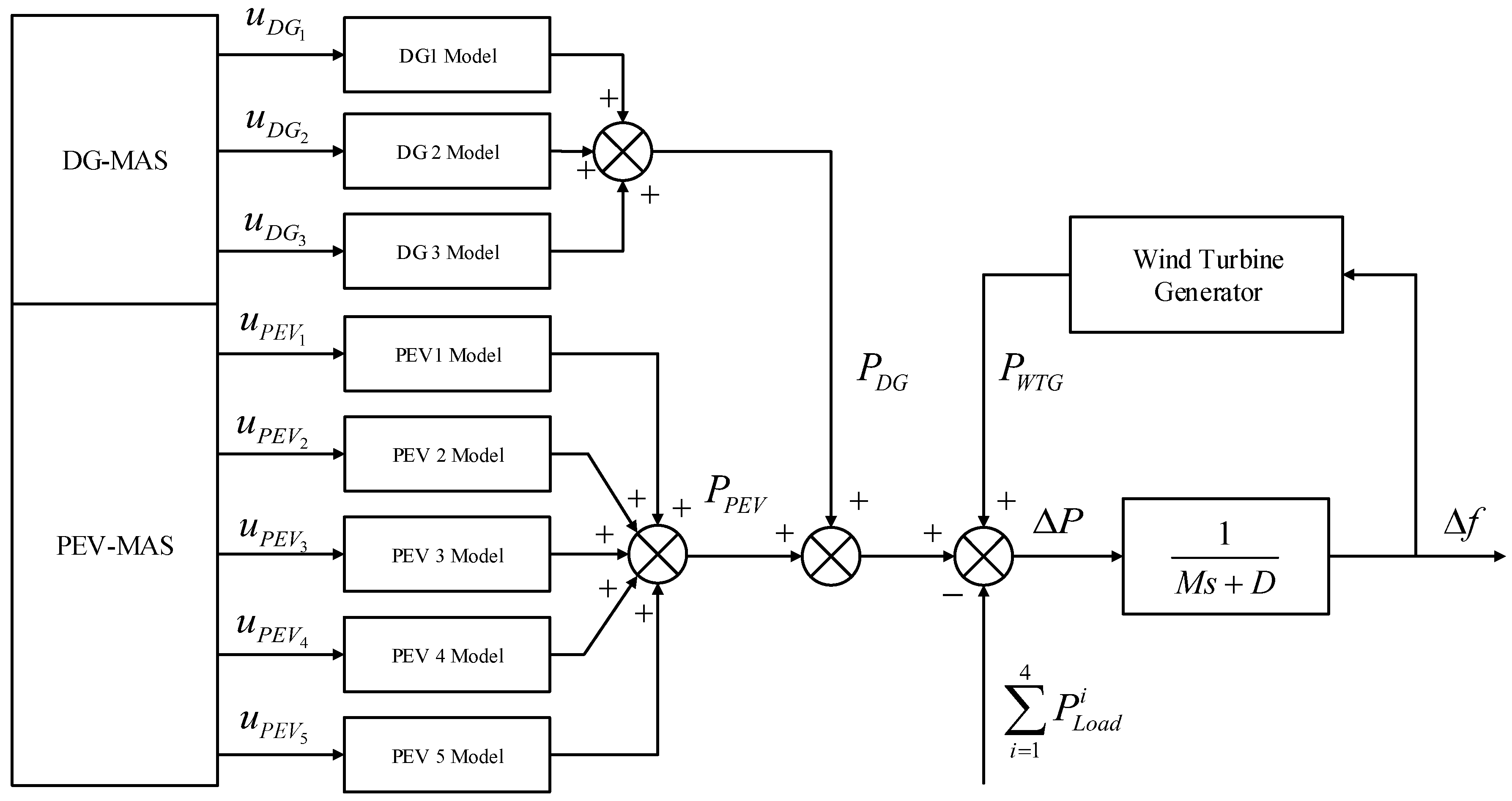
Combined with the model described in
Section 3 and the aforementioned control theory, the structure of the proposed microgrid frequency control strategy is shown in
Figure 8. Then, the fully-distributed control of microgrid frequency regulation can be realized by this control strategy. Theoretically, the proposed control strategy can guarantee the stability of the microgrid, and its performances are better than most of the previous studies. Numerical simulations will be carried out to demonstrate the validity of the proposed control strategy in
Section 5.
5. Simulation Results and Analysis
At the beginning of the simulation experiments, each part of microgrid power system is operating in the steady state. The simulations are based on the MATLAB/Simulink environment, and the step time is set to 0.001 s. Furthermore, the controller parameters are optimized by the genetic algorithm-based particle swarm optimization algorithm. The fitness function is calculated by the sum of the rate of change of frequency (RoCoF) and the integral of the time-weighted absolute value of the error (ITAE), which is described by Equations (20)–(22).
In the following part, the effectiveness of the proposed control strategy is demonstrated by two different simulation cases including: Case A: simulations are under load demand change and PEV power change without considering stochastic disturbances; Case B: simulations consider stochastic disturbances of load demand, WTG and PEV.
The parameters of CCS-ILADRC used for the simulation are shown in
Table 3 and the parameters of DCS-ILADRC used for simulation are shown in
Table 4.
5.1. Case A
This case investigates the frequency stability under load demand change and PEV output change. The output of load demand changes from 1 p.u. to 1.1 p.u. at 1 s, and output changes from 0 p.u. to 0.1 p.u. at 5 s. The initial states of DG, WTG and PEV are supposed to be stable.
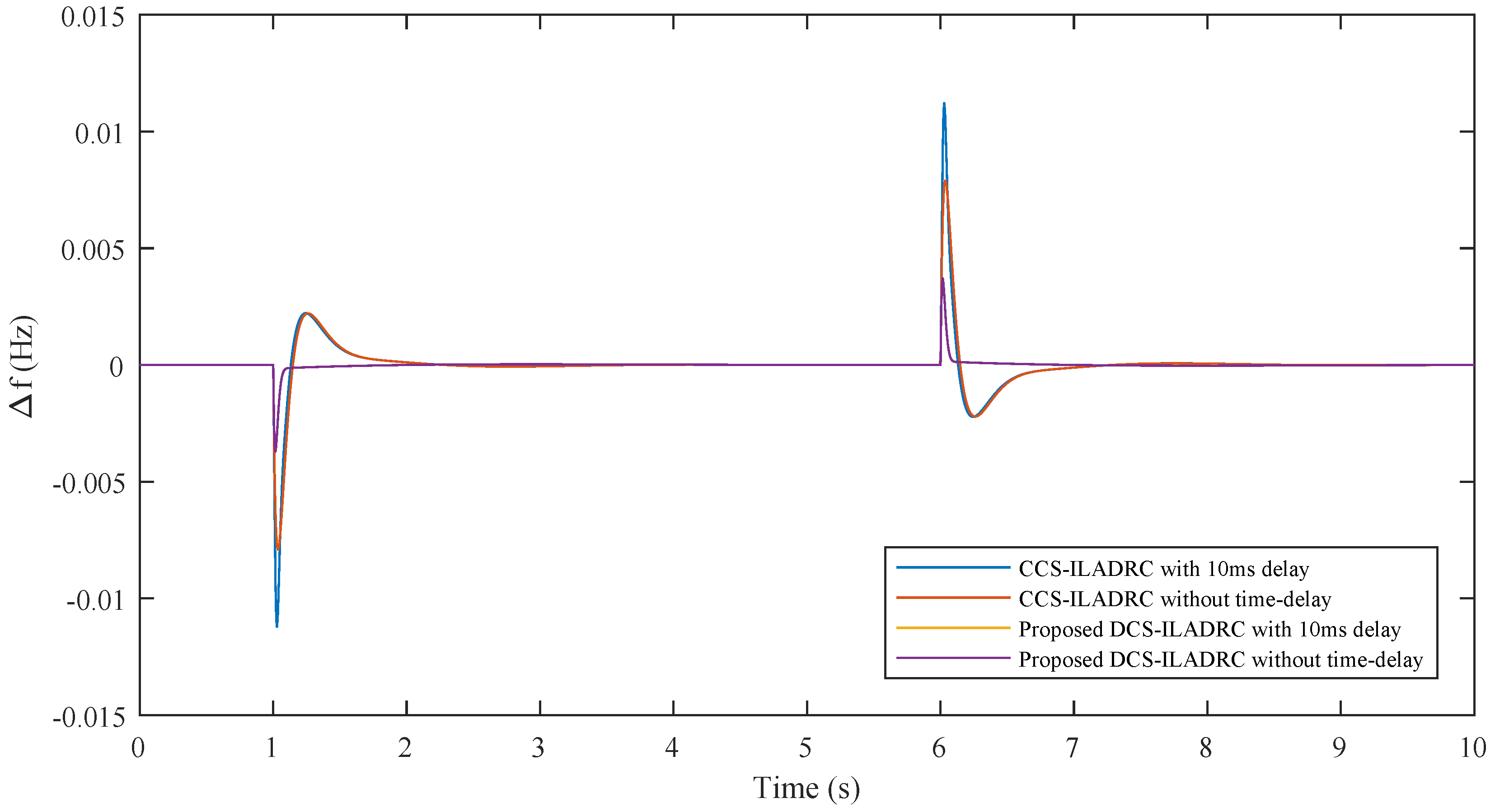
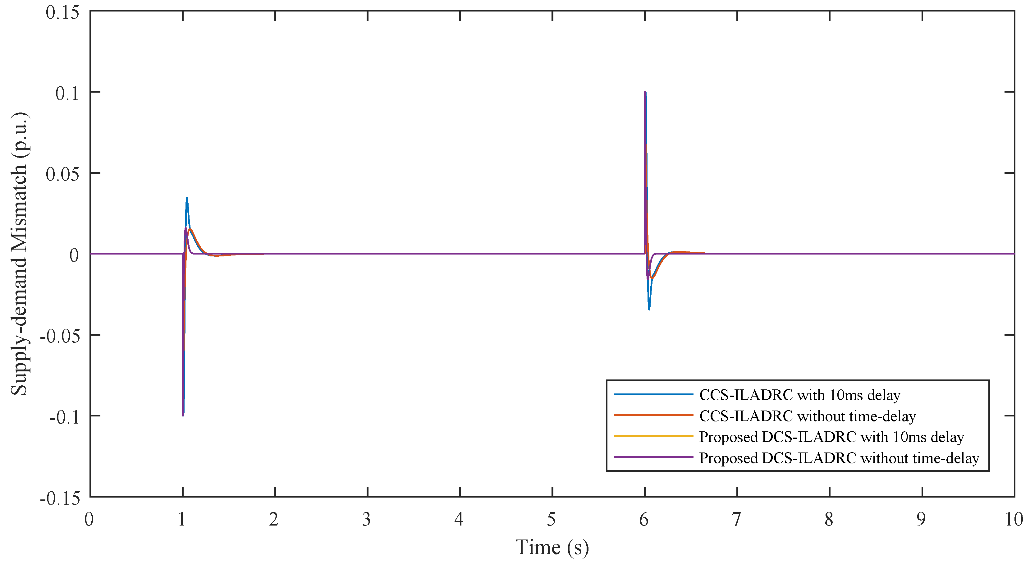
Firstly, system performances based on CCS-ILADRC without time delay, CCS-ILADRC with a 10-ms delay, DCS-ILADRC without time delay and DCS-ILADRC with a 10-ms delay are studied to demonstrate the superiority of the proposed DCS-ILADRC. The transient responses of the system frequency deviation are shown in
Figure 9, and the transient responses of supply-demand mismatch are shown in
Figure 10. After the increase of load demand, the frequency deviation can be well eliminated. It is obvious that the system performances based on the proposed DCS-ILADRC are the best among those based on the other three control strategies.
Without considering the time delay, the settling time based on the proposed DCS-ILADRC is 0.542 s, which is shorter than 1.490 s of the system based on CCS-ILADRC. The frequency overshoot and fitness value based on DCS-ILADRC are decreased to −3.711
Hz and 2.017
Hz, respectively. The detailed comparison results are described in
Table 5. Similarly, the simulation results under the change of PEV power can also indicate the superiority of the system based on the proposed DCS-ILADRC.
Furthermore, suppose that the communication and calculation delay is 10 ms; it is obvious that the negative effect caused by time delay can be well avoided based on the proposed DCS-ILADRC. The performances based on DCS-ILADRC with different time delays are almost unchanged. However, system performances based on CCS-ILADRC greatly depend on the communication and calculation delay. Thus, the proposed control strategy can protect the system from the time delay effect. Most of the previous works decrease the time delay effect through modifying advanced control theory or accelerating the convergent speed of MAS. However, there still exits a non-negligible negative effect caused by time delay. The proposed distributed control strategy provides a new idea for researchers.
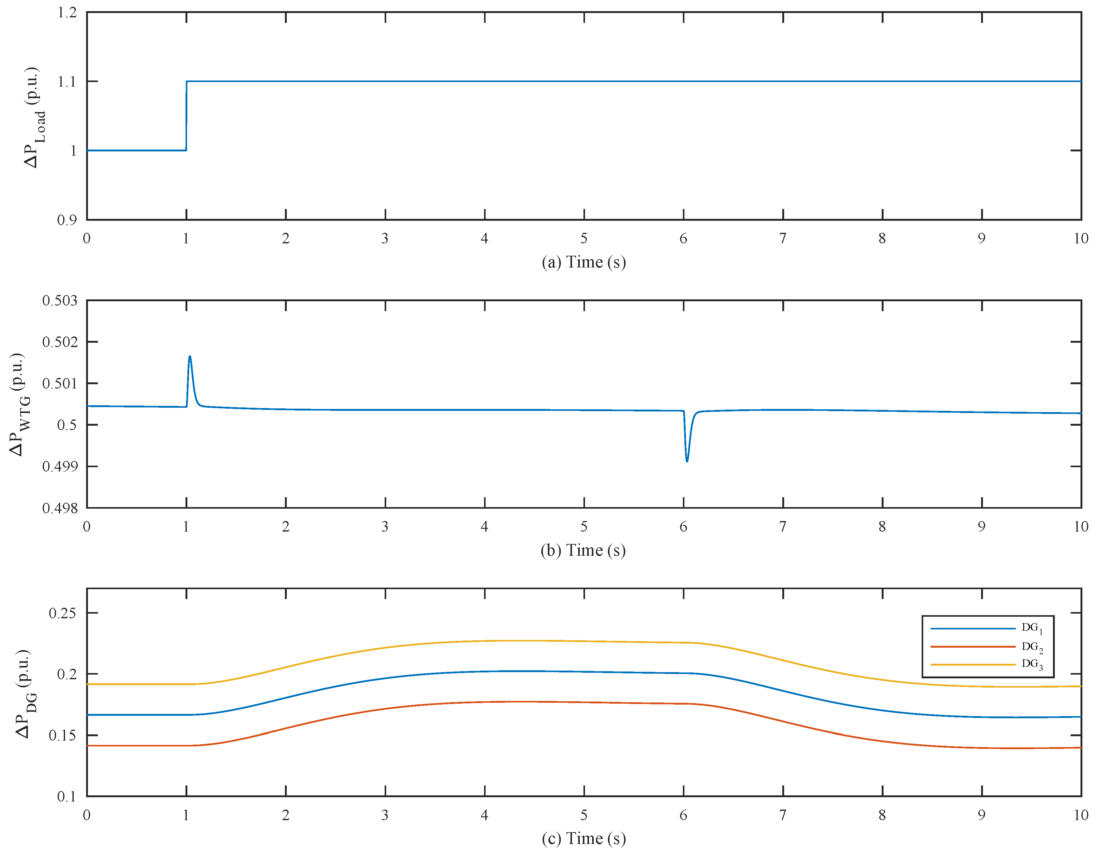
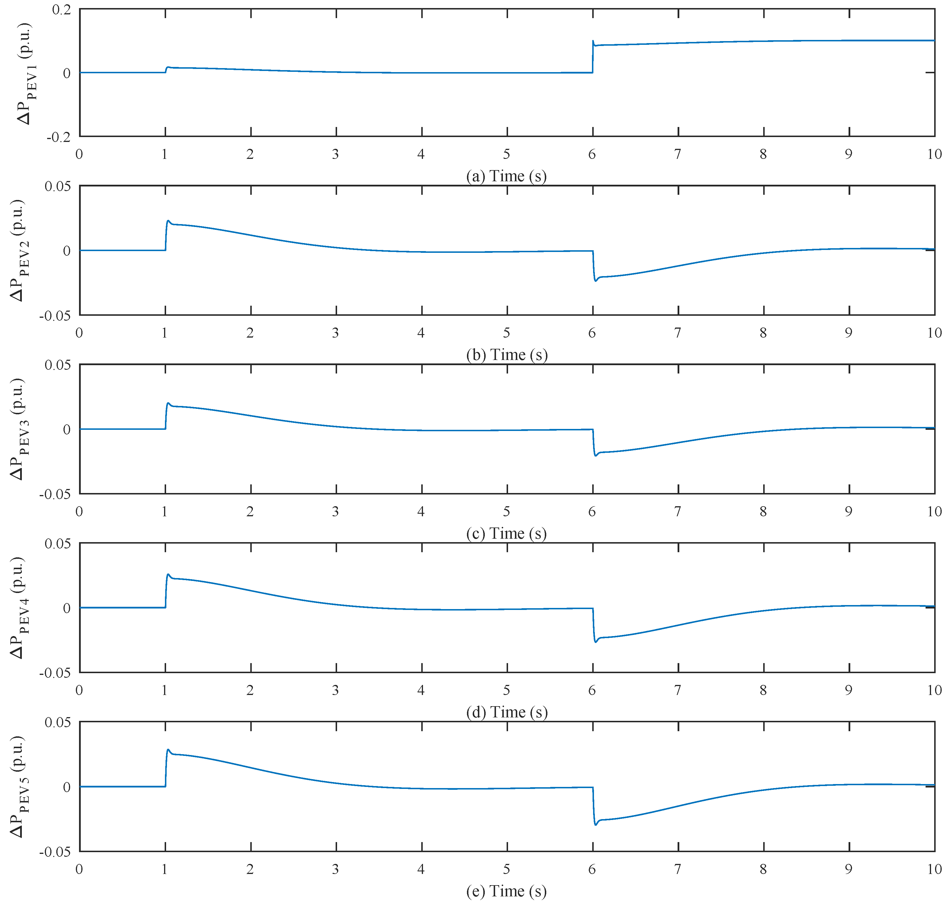
Based on the above analysis, the frequency stability can be greatly guaranteed by the proposed control strategy. For the purpose of deeply analyzing the performances of DCS-ILADRC, the transient power outputs of load demand, WTG, DG and PEV are shown in
Figure 11 and
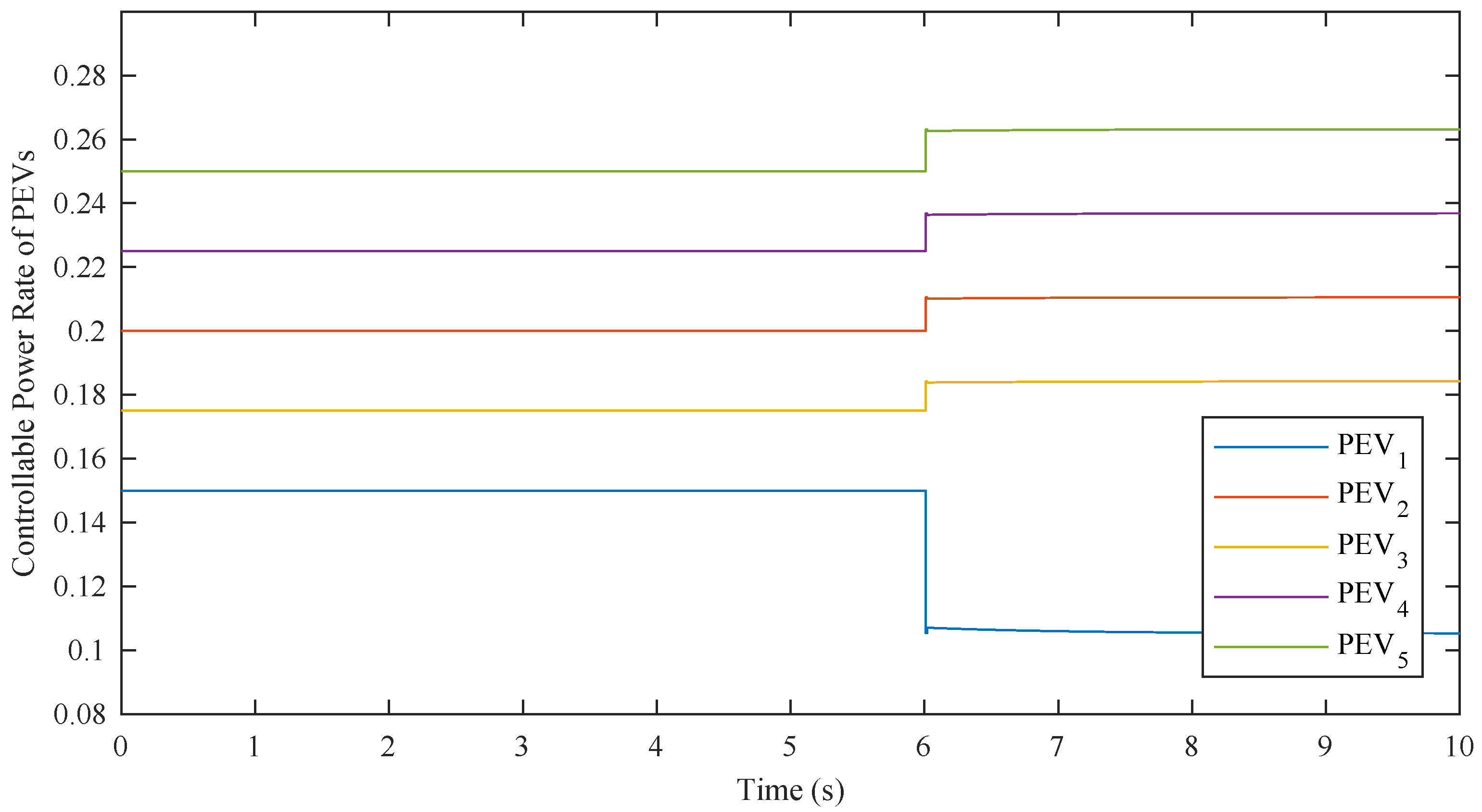
Figure 12. Obviously, the multi-agent system of PEVs based on ILADRC can realize a fast frequency recovery. When system frequency is in a stable state, the output power of PEVs returns to its initial state by the compensation of DGs. This ensures that the PEVs can operate at the maximum charging rate most of the time. In contrast, most of the previous works only considered the contribution of PEVs to the frequency regulation, which may result in the PEVs not being able to be fully charged when people need them. Moreover, the WTG also contributes to the frequency regulation once the frequency deviation has occurred. Finally, the controllable power rate of PEVs is shown in
Figure 13.
5.2. Case B
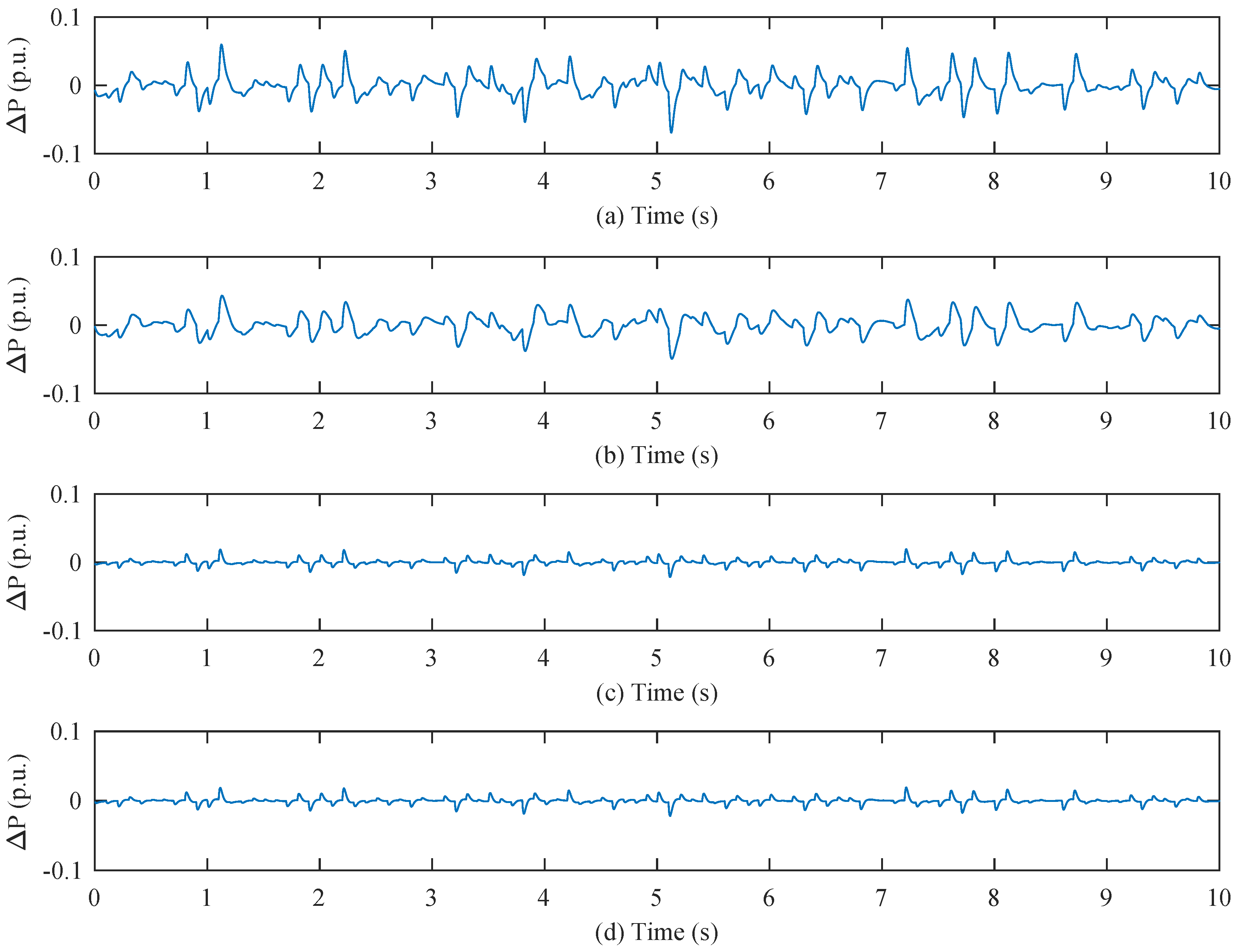
It is of significantly practical importance to investigate the system anti-disturbance ability under the stochastic disturbance of load demand, WTG and PEVs’ output, especially with the stochastic and fluctuating power of PEVs. Accordingly, this case study’s frequency deviation profile is caused by stochastic changes of each system component output. The frequency transient responses and supply-demand mismatch based on different control strategies are described in
Figure 14 and
Figure 15, respectively. As seen in
Figure 14, the variation range of
with DCS-ILADRC without time delay is between −3.072
Hz to 2.879
Hz, which is extremely smaller than that with CCS-ILADRC.
is reduced to 0.8546. The comparison data are shown in
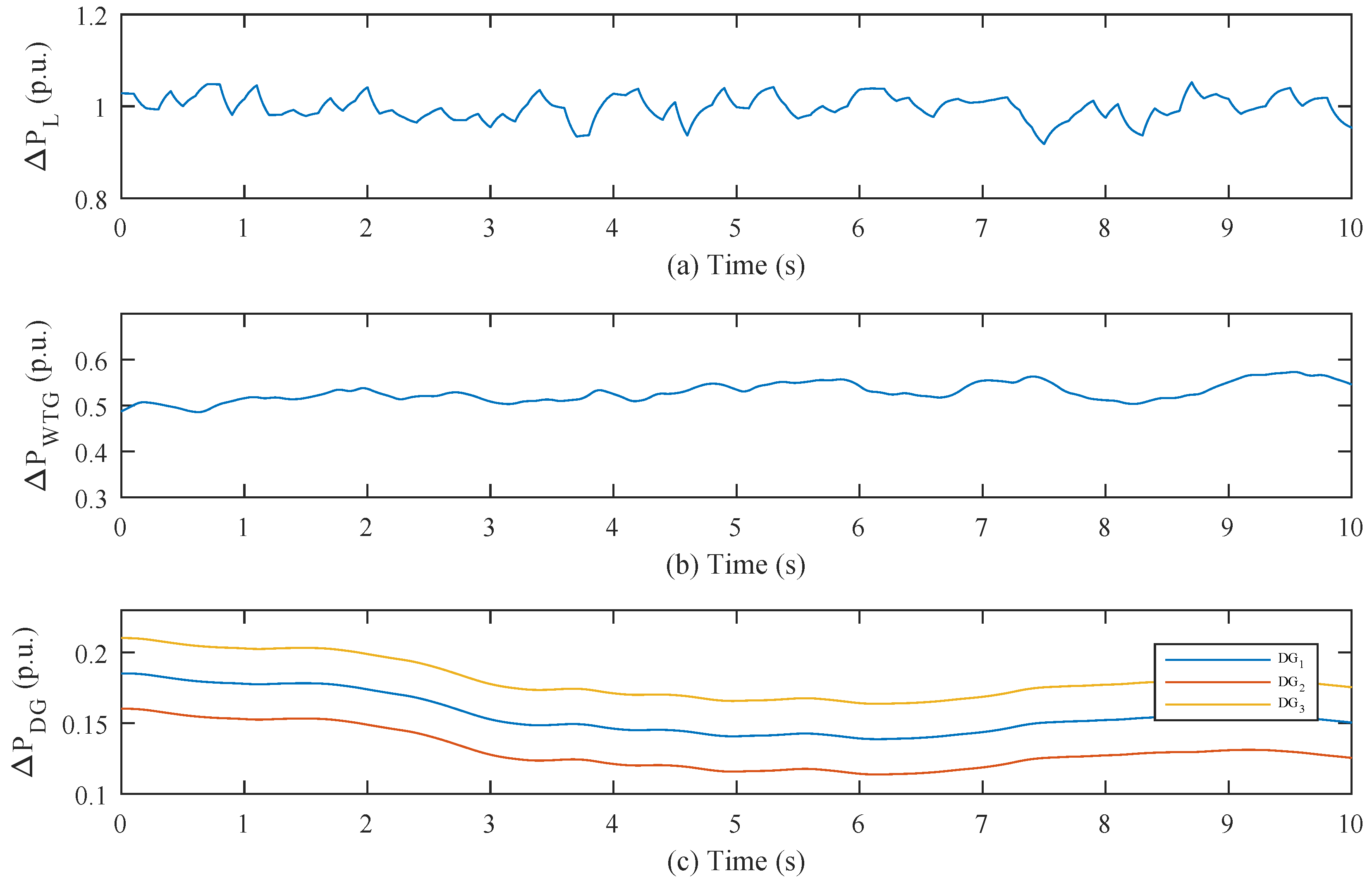
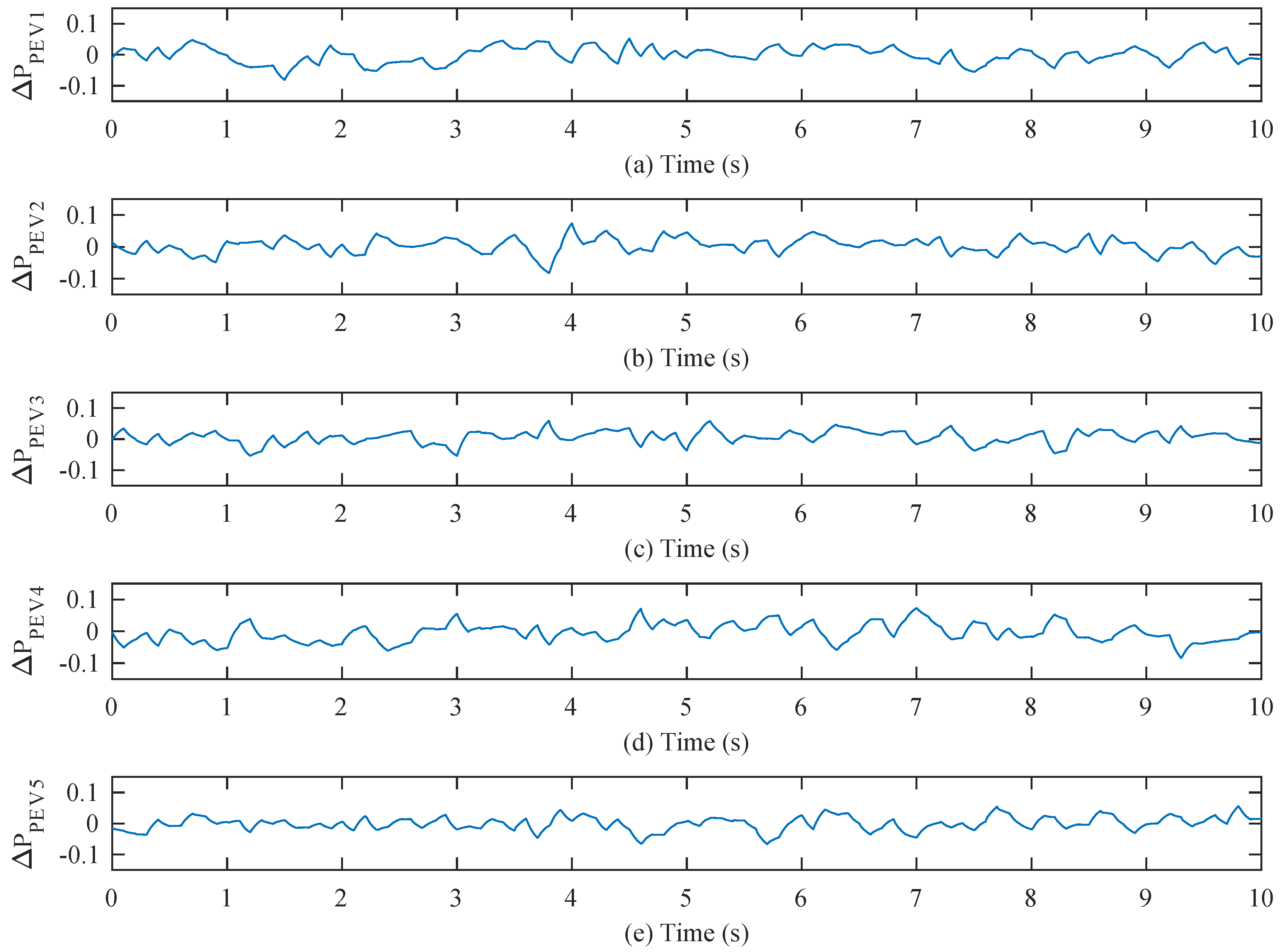
Table 6. The transient responses of the power output of each component are shown in
Figure 16 and
Figure 17.
Therefore, the simulation results declare the effectiveness of the proposed control strategy. It can be obviously found that microgrid based on DCS-ILADRC has better anti-disturbance capability. The ILADRC-based controllers directly control the PEVs to eliminate the frequency deviation, which gives full play to the PEVs’ advantages and avoids the negative effects caused by time delay. With the supplementary calculation of CPR, PEVs can contribute to the frequency regulation within their normal operating condition. The aforementioned aspects further demonstrate the effectiveness of the proposed control strategy.


