Experimental Investigation on Effect of Wall Roughness and Lubricant Film on the Adhered Fuel Film of N-Butanol-Diesel Blends after Spray Impingement

 ,
,
Abstract
:1. Introduction
2. Materials and Methods
2.1. Experimental Apparatus and Materials
2.2. Experimental Conditions
2.3. Adhered Film Characteristic Parameters
2.3.1. Adhered Fuel Mass Ratio
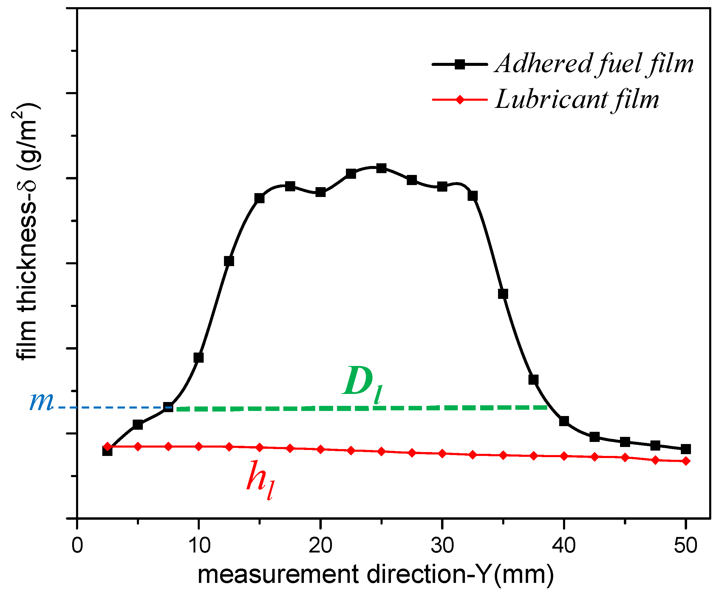
2.3.2. Longitudinal Section Profiles of Adhered Fuel Film
2.3.3. Average Thickness (ha) and Accumulated Diameter (Dl) of Adhered Film
3. Results and Discussion
3.1. Development of Adhering Fuel Mass Ratio
3.2. Adhered Fuel Film-Thickness Distribution
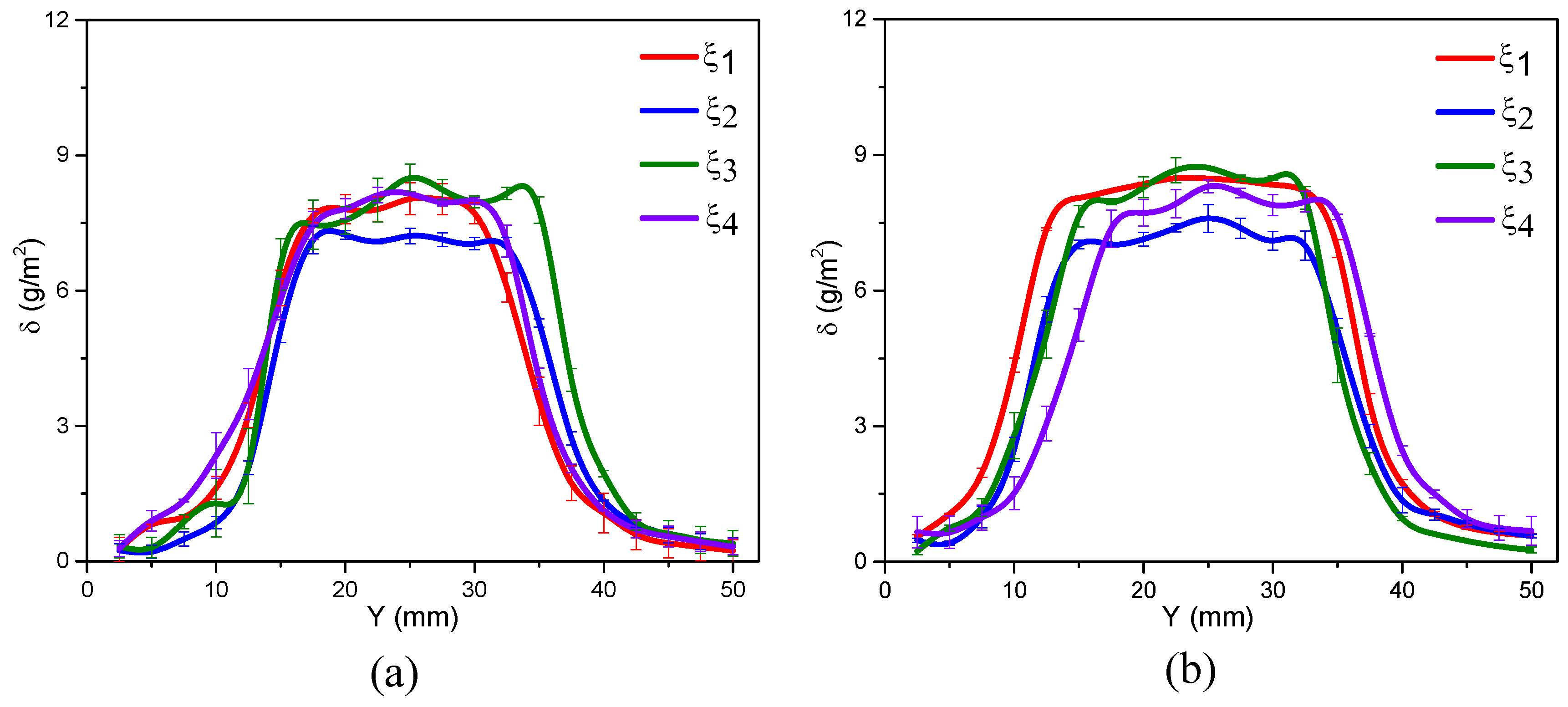
3.2.1. Dry Wall Conditions
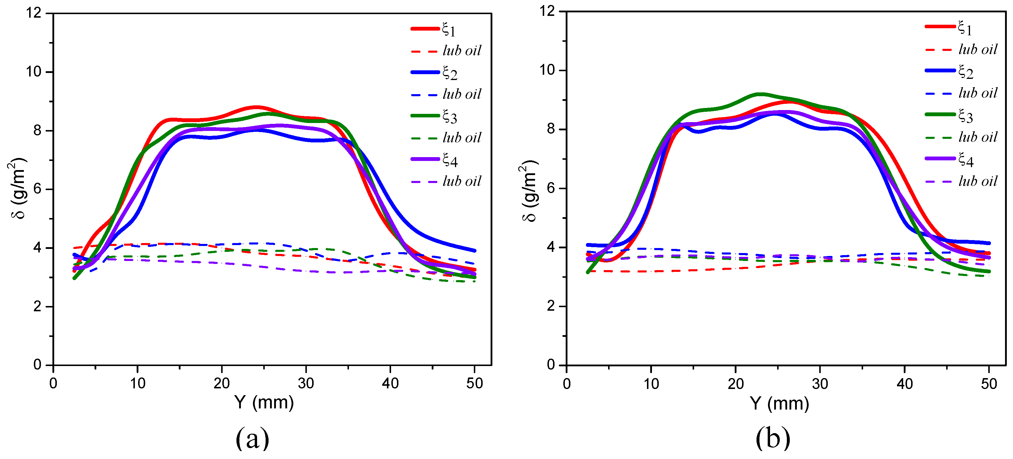
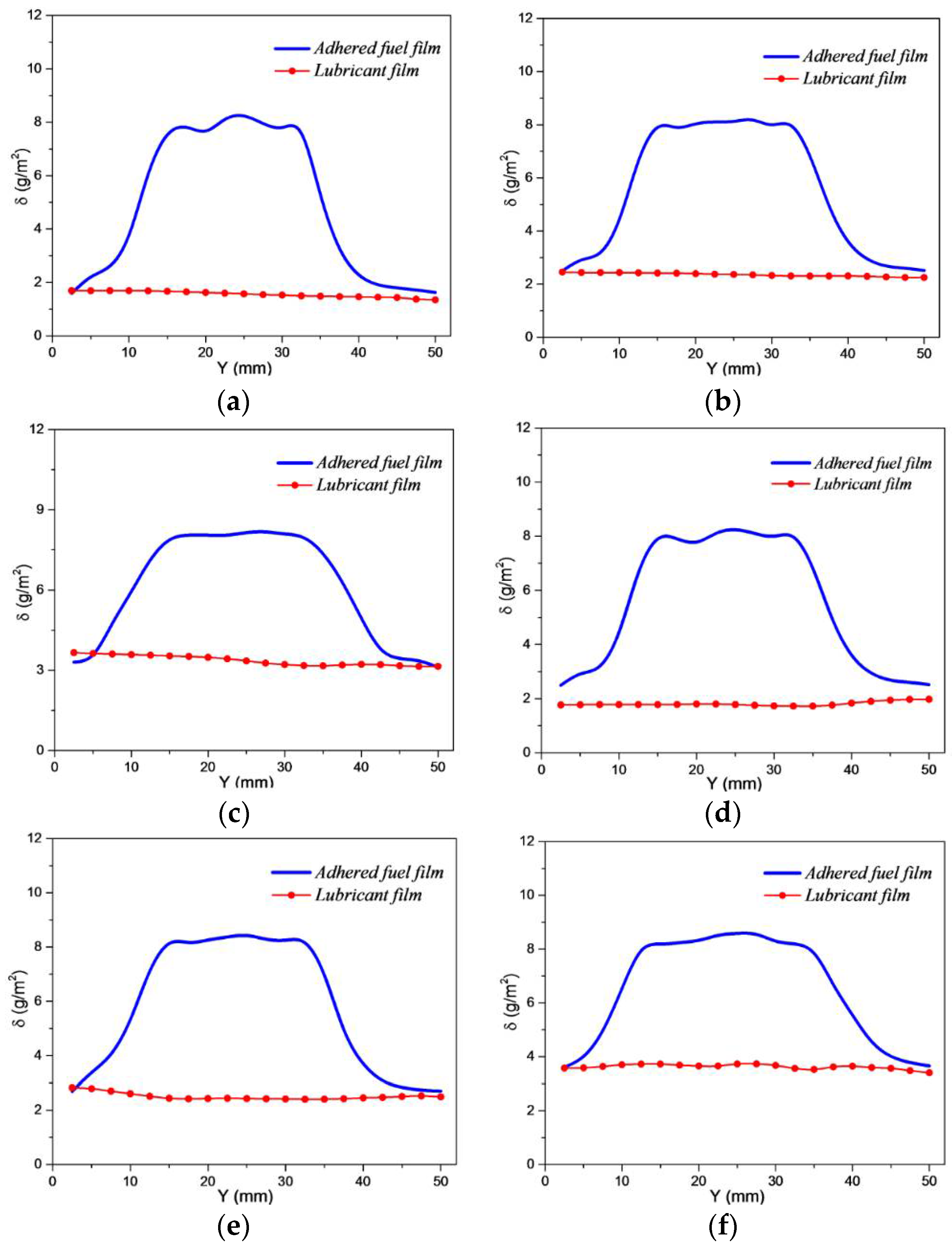
3.2.2. FWW Conditions
3.2.3. SWW Conditions
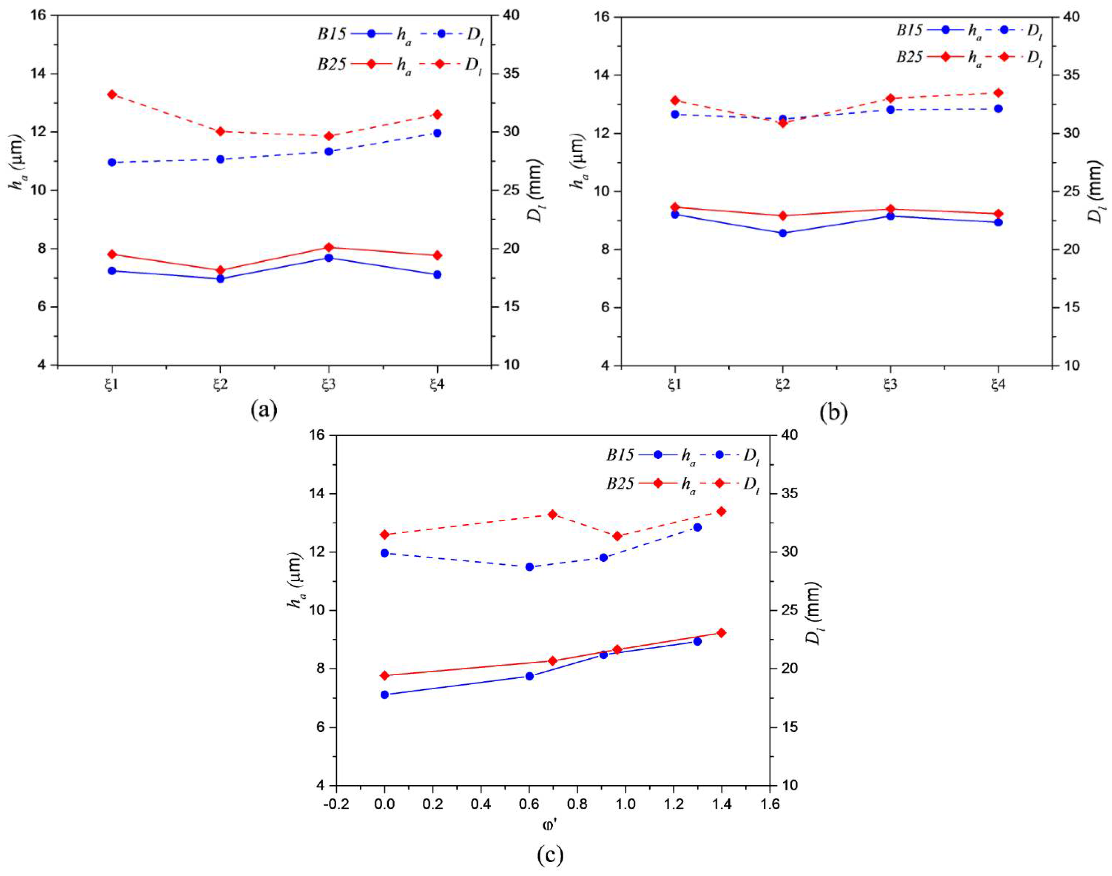
3.3. Average Thickness (ha) and Accumulated Diameter (Dl)
4. Conclusions
- (1)
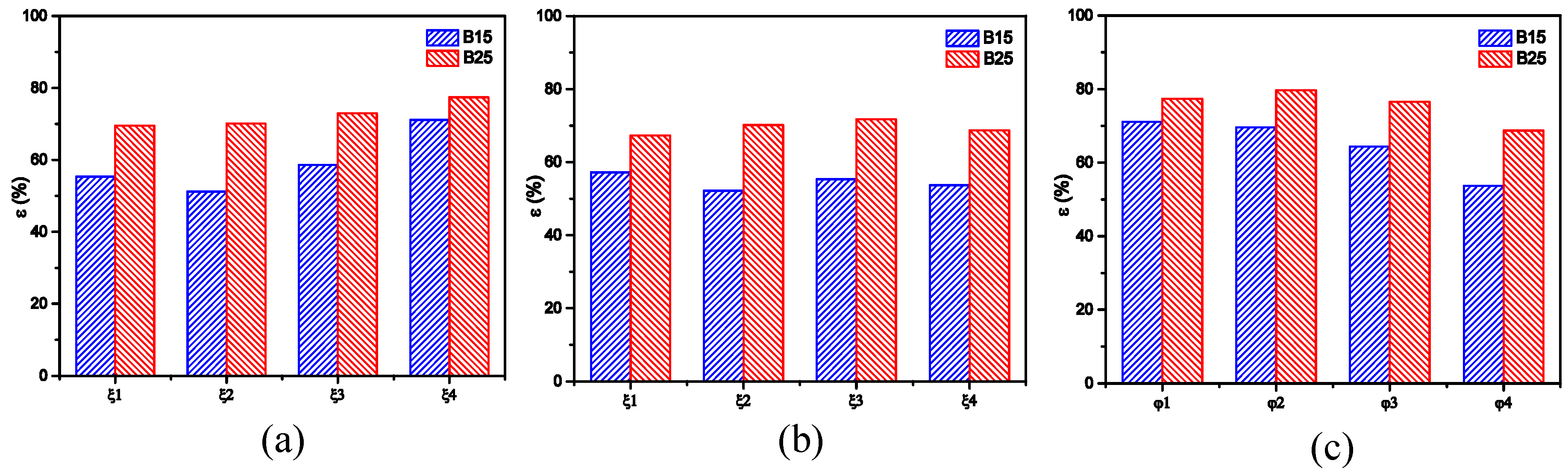
- The adhered fuel film mass ratio ε of B25 is larger than B15 for a lower splashing mass of B25 that is caused by the smaller impinged momentum. However, gaps of ε between different surface roughness types became inconspicuous with an increase in n-butanol blending ratio. ε increases with a rise in roughness Sq under dry wall conditions, but decreases with an increase in lube oil film thickness under FWW conditions.
- (2)
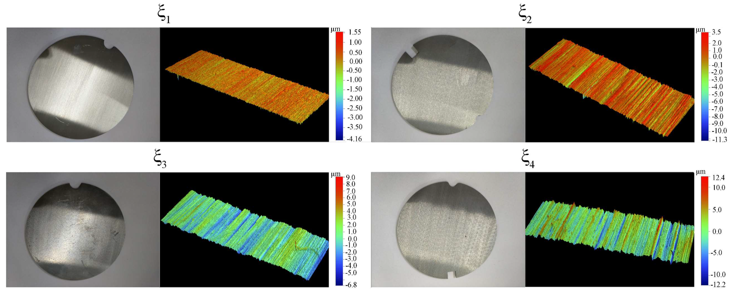
- The thickness distribution of the adhered fuel film does not change much with different Sa or Sq, but the film profile of the ξ2 wall showed a lower shape than others, which signifies that Sa or Sq were not the only parameters that were used to evaluate the effect of roughness. This plate has a lower Ssk, which determined the overall concave–convex degree of the wall. The influence of roughness was insignificant for a lubricant film thickness that was greater than Sq.
- (3)
- The mean thickness ha and accumulated diameter Dl of B25 were higher than those of B15 under almost all conditions and stable developments of ha and Dl resulted in dry walls and FWW. Both were enhanced by an increase in φ’, which implies that, under thinner lubricant film conditions (φ’ < 1), the wall roughness is an important factor that cannot be ignored for an impacting process.
Author Contributions
Funding
Acknowledgments
Conflicts of Interest
Abbreviations
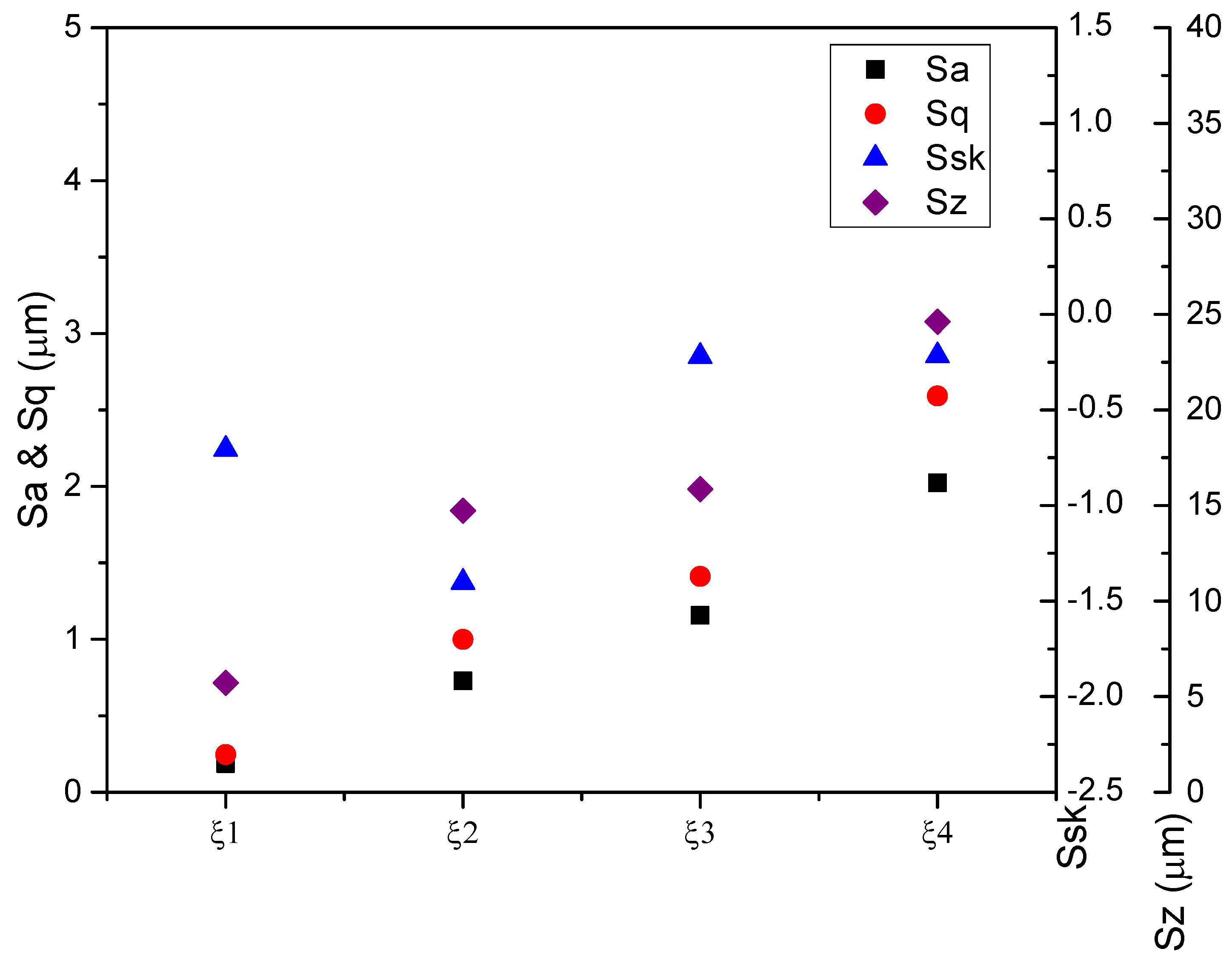
| Sq | surface roughness parameter-root mean square height (µm) |
| hl | mean thickness of original lubricant film (g/m2) |
| SWW | semi-wetted walls |
| FWW | fully wetted walls |
| B15/B25 | 15%/25% volumetric blended ratio of n-butanol in blending fuels |
| ε | adhering fuel mass ratio (%) |
| Ssk | surface roughness parameter-skewness |
| ha | mean thickness of adhered fuel film (µm) |
| Dl | accumulated diameter of adhered fuel film (mm) |
| Ra | one-dimensional surface roughness parameter-Arithmetic mean height (µm) |
| Rq | root mean square deviation of a line (µm) |
| Sa | two-dimensional surface roughness parameter-Arithmetic mean height (µm) |
| ξ1–ξ4 | four walls with increasing surface roughness Sq |
| A | area of the measured region for surface roughness |
| φ’ | φ’ = hl/Sq |
| Δml | the mass loss of lube oil in the impingement process (mg) |
| Y | the measurement direction of the adhered fuel film thickness (mm) |
| δ | liquid film thickness (g/m2) |
| φ | conditions with different original lubricant film thicknesses |
References
- Yao, M.; Zheng, Z.; Liu, H. Progress and recent trends in homogeneous charge compression ignition (HCCI) engines. Prog. Energy Combust. Sci. 2009, 35, 398–437. [Google Scholar] [CrossRef]
- Coskun, G.; Soyhan, H.S.; Demir, U.; Turkcan, A.; Ozsezen, A.N.; Canakci, M. Influences of second injection variations on combustion and emissions of an HCCI-DI engine: Experiments and CFD modelling. Fuel 2014, 136, 287–294. [Google Scholar] [CrossRef]
- D’Ambrosio, S.; Ferrari, A. Effects of exhaust gas recirculation in diesel engines featuring late PCCI type combustion strategies. Energy Convers. Manag. 2015, 105, 1269–1280. [Google Scholar] [CrossRef]
- Kiplimo, R.; Tomita, E.; Kawahara, N.; Yokobe, S. Effects of spray impingement, injection parameters, and EGR on the combustion and emission characteristics of a PCCI diesel engine. Appl. Therm. Eng. 2012, 37, 165–175. [Google Scholar] [CrossRef]
- Kook, S.; Park, S.; Bae, C. Influence of early fuel injection timings on premixing and combustion in a diesel engine. Energy Fuels 2007, 22, 331–337. [Google Scholar] [CrossRef]
- Akop, M.; Zama, Y.; Furuhata, T.; Arai, M. Characteristics of adhesion of diesel fuel on impingement disk wall. Part 1: Effect of impingement area and inclination angle of disk. At. Sprays 2013, 23, 725–744. [Google Scholar] [CrossRef]
- Akop, M.; Zama, Y.; Furuhata, T.; Arai, M. Characteristics of adhesion diesel fuel on an impingement disk wall. Part 3: Ambient pressure effect. At. Sprays 2014, 24, 625–650. [Google Scholar] [CrossRef]
- Oliveira Panão, M.R.; Moreira, A.L.N.; Durão, D.F.G. Effect of a cross-flow on spray impingement with port fuel injection systems for HCCI engines. Fuel 2013, 106, 249–257. [Google Scholar] [CrossRef]
- Wang, Z.; Guo, H.; Wang, C.; Xu, H.; Li, Y. Microscopic level study on the spray impingement process and characteristics. Appl. Energy 2017, 197, 114–123. [Google Scholar] [CrossRef]
- Zhang, Z.; Chi, Y.; Shang, L.; Zhang, P.; Zhao, Z. On the role of droplet bouncing in modeling impinging sprays under elevated pressures. Int. J. Heat Mass Transf. 2016, 102, 657–668. [Google Scholar] [CrossRef]
- Estrade, J.; Carentz, H.; Lavergne, G.; Biscos, Y. Experimental investigation of dynamic binary collision of ethanol droplets-a model for droplet coalescence and bouncing. Int. J. Heat Fluid Flow 1999, 20, 486–491. [Google Scholar] [CrossRef]
- Moreira, A.L.N.; Moita, A.S.; Panão, M.R. Advances and challenges in explaining fuel spray impingement: How much of single droplet impact research is useful? Prog. Energy Combust. Sci. 2010, 36, 554–580. [Google Scholar] [CrossRef]
- Deendarlianto; Takata, Y.; Kohno, M.; Hidaka, S.; Wakui, T.; Majid, A.I.; Kuntoro, H.Y.; Indarto; Widyaparaga, A. The effects of the surface roughness on the dynamic behavior of the successive micrometric droplets impacting onto inclined hot surfaces. Int. J. Heat Mass Transf. 2016, 101, 1217–1226. [Google Scholar] [CrossRef]
- Tang, C.; Qin, M.; Weng, X.; Zhang, X.; Zhang, P.; Li, J.; Huang, Z. Dynamics of droplet impact on solid surface with different roughness. Int. J. Multiph. Flow 2017, 96, 56–69. [Google Scholar] [CrossRef]
- Zhang, Z.; Liu, H.; Zhang, F.; Yao, M. Numerical study of spray micro-droplet impinging on dry/wet wall. Appl. Therm. Eng. 2016, 95, 1–9. [Google Scholar] [CrossRef]
- Guo, Y.; Wei, L.; Liang, G.; Shen, S. Simulation of droplet impact on liquid film with CLSVOF. Int. Commun. Heat Mass Transf. 2014, 53, 26–33. [Google Scholar] [CrossRef]
- Lee, C.S.; Choi, N.J. Effect of air injection on the characteristics of transient response in a turbocharged diesel engine. Int. J. Therm. Sci. 2002, 41, 63–71. [Google Scholar] [CrossRef]
- Imdadul, H.K.; Masjuki, H.H.; Kalam, M.A.; Zulkifli, N.W.M.; Alabdulkarem, A.; Rashed, M.M.; Teoh, Y.H.; How, H.G. Higher alcohol–biodiesel–diesel blends: An approach for improving the performance, emission, and combustion of a light-duty diesel engine. Energy Convers. Manag. 2016, 111, 174–185. [Google Scholar] [CrossRef]
- Rakopoulos, D.C.; Rakopoulos, C.D.; Giakoumis, E.G.; Dimaratos, A.M.; Kyritsis, D.C. Effects of butanol–diesel fuel blends on the performance and emissions of a high-speed DI diesel engine. Energy Convers. Manag. 2010, 51, 1989–1997. [Google Scholar] [CrossRef]
- Polat, S. An experimental study on combustion, engine performance and exhaust emissions in a HCCI engine fuelled with diethyl ether–ethanol fuel blends. Fuel Process. Technol. 2016, 143, 140–150. [Google Scholar] [CrossRef]
- Ge, J.; Yoon, S.; Choi, N. Using Canola Oil Biodiesel as an Alternative Fuel in Diesel Engines: A Review. Appl. Sci. 2017, 7, 881. [Google Scholar] [CrossRef]
- Lapuerta, M.; Armas, O.; Rodriguezfernandez, J. Effect of biodiesel fuels on diesel engine emissions. Prog. Energy Combust. Sci. 2008, 34, 198–223. [Google Scholar] [CrossRef]
- Huang, H.; Liu, Q.; Yang, R.; Zhu, T.; Zhao, R.; Wang, Y. Investigation on the effects of pilot injection on low temperature combustion in high-speed diesel engine fueled with n -butanol–diesel blends. Energy Convers. Manag. 2015, 106, 748–758. [Google Scholar] [CrossRef]
- Doğan, O. The influence of n-butanol/diesel fuel blends utilization on a small diesel engine performance and emissions. Fuel 2011, 90, 2467–2472. [Google Scholar] [CrossRef]
- Mo, J.; Tang, C.; Li, J.; Guan, L.; Huang, Z. Experimental investigation on the effect of n-butanol blending on spray characteristics of soybean biodiesel in a common-rail fuel injection system. Fuel 2016, 182, 391–401. [Google Scholar] [CrossRef]
- Chen, Z.; Liu, J.; Han, Z.; Du, B.; Liu, Y.; Lee, C. Study on performance and emissions of a passenger-car diesel engine fueled with butanol–diesel blends. Energy 2013, 55, 638–646. [Google Scholar] [CrossRef]
- Yao, M.; Wang, H.; Zheng, Z.; Yue, Y. Experimental study of n-butanol additive and multi-injection on HD diesel engine performance and emissions. Fuel 2010, 89, 2191–2201. [Google Scholar] [CrossRef]
- Şahin, Z.; Aksu, O.N. Experimental investigation of the effects of using low ratio n-butanol/diesel fuel blends on engine performance and exhaust emissions in a turbocharged DI diesel engine. Renew. Energy 2015, 77, 279–290. [Google Scholar] [CrossRef]
- Yilmaz, N.; Vigil, F.M.; Benalil, K.; Davis, S.M.; Calva, A. Effect of biodiesel–butanol fuel blends on emissions and performance characteristics of a diesel engine. Fuel 2014, 135, 46–50. [Google Scholar] [CrossRef]
- Yu, H.; Liang, X.; Shu, G.; Sun, X.; Zhang, H. Experimental investigation on wall film ratio of diesel, butanol/diesel, DME/diesel and gasoline/diesel blended fuels during the spray wall impingement process. Fuel Process. Technol. 2017, 156, 9–18. [Google Scholar] [CrossRef]
- Yu, H.; Liang, X.; Shu, G.; Wang, X.; Wang, Y.; Zhang, H. Experimental Investigation on Wall Film Distribution of Dimethyl Ether/Diesel Blended Fuels Formed during Spray Wall Impingement. Energies 2016, 9, 949. [Google Scholar] [CrossRef]
- Yu, H.; Liang, X.; Shu, G.; Wang, Y.; Zhang, H. Experimental investigation on spray-wall impingement characteristics of n-butanol/diesel blended fuels. Fuel 2016, 182, 248–258. [Google Scholar] [CrossRef]
- Thongcha., S.; Chollacoop, N.; Topaiboul, S.; Suwannakij, K.; Charoenphonphanich, C.; Hanamura, K. Feasibility Study of Using High Butanol-Diesel Blends in Commonrail Engine. In Proceedings of the 23rd Conference of the Mechanical Engineering Network of Thailand, Chiang Mai, Thailand, 4–7 November 2009. [Google Scholar]
- Tong, J. Thermal Physical Properties of the Fluid: Basic Principle and Calculation; China Petrochemical Press: Beijing, China, 2008. [Google Scholar]
- Zhang, H.; Liang, X.; Yu, H.; Wang, Y.; Weijian, C. Experimental Study on the Adhering Fuel Film of the Impinged N-Butanol-Diesel Blends. In Proceedings of the ASME 2016 International Mechanical Engineering Congress and Exposition, Phoenix, AZ, USA, 11–17 November 2016. [Google Scholar]
- Fuwa, K.; Valle, B. The Physical Basis of Analytical Atomic Absorption Spectrometry. The Pertinence of the Beer-Lambert Law. Anal. Chem. 1963, 35, 942–946. [Google Scholar] [CrossRef]
- Introduction to Roughness-Parameters of Surface Roughness. Available online: https://www.keyence.com/ss/products/microscope/roughness/surface/sq-root-mean-square-height.jsp (accessed on 5 June 2018).
- Liang, G.; Mudawar, I. Review of mass and momentum interactions during drop impact on a liquid film. Int. J. Heat Mass Transf. 2016, 101, 577–599. [Google Scholar] [CrossRef]
- Kalantari, D.; Tropea, C. Spray impact onto flat and rigid walls: Empirical characterization and modelling. Int. J. Multiph. Flow 2007, 33, 525–544. [Google Scholar] [CrossRef]


| Fuel Abbreviation | Density (kg/m3) | Dynamic Viscosity (×10−3 pa·s) | Surface Tension (mN/m) |
|---|---|---|---|
| B15 | 849.8 | 3.627 | 26.03 |
| B25 | 845.1 | 3.491 | 25.57 |
| Pure diesel | 856.5 | 3.847 | 26.67 |
| Roughness Parameter | Definition Formula |
|---|---|
| Arithmetic mean height (Sa) | |
| Root mean square height (Sq) | |
| Skewness (Ssk) | |
| Maximum height (Sz) |
| Experiment Parameter | Conditions |
|---|---|
| Fuel | B15, B25 |
| Ambient temperature | 20 °C |
| Ambient pressure | 0.1 MPa |
| Injection pressure | 80 MPa |
| impingement distance | 60 mm |
| Wall condition | Dry/FWW/SWW |
© 2018 by the authors. Licensee MDPI, Basel, Switzerland. This article is an open access article distributed under the terms and conditions of the Creative Commons Attribution (CC BY) license (http://creativecommons.org/licenses/by/4.0/).
Share and Cite
Liang, X.; Zhang, H.; Shu, G.; Wang, Y.; Sun, X.; Yu, H.; Ge, M. Experimental Investigation on Effect of Wall Roughness and Lubricant Film on the Adhered Fuel Film of N-Butanol-Diesel Blends after Spray Impingement. Energies 2018, 11, 1576. https://doi.org/10.3390/en11061576
Liang X, Zhang H, Shu G, Wang Y, Sun X, Yu H, Ge M. Experimental Investigation on Effect of Wall Roughness and Lubricant Film on the Adhered Fuel Film of N-Butanol-Diesel Blends after Spray Impingement. Energies. 2018; 11(6):1576. https://doi.org/10.3390/en11061576
Chicago/Turabian StyleLiang, Xingyu, Hongsheng Zhang, Gequn Shu, Yuesen Wang, Xiuxiu Sun, Hanzhengnan Yu, and Ming Ge. 2018. "Experimental Investigation on Effect of Wall Roughness and Lubricant Film on the Adhered Fuel Film of N-Butanol-Diesel Blends after Spray Impingement" Energies 11, no. 6: 1576. https://doi.org/10.3390/en11061576