Advanced Thermodynamic Analysis Applied to an Integrated Solar Combined Cycle System


1
Key Laboratory of Condition Monitoring and Control for Power Plant Equipment, Ministry of Education, North China Electric Power University, Beijing 102206, China
2
School of Energy Power and Mechanical Engineering, North China Electric Power University, Beijing 102206, China
*
Author to whom correspondence should be addressed.
Energies 2018, 11(6), 1574; https://doi.org/10.3390/en11061574
Submission received: 24 May 2018
/
Revised: 7 June 2018
/
Accepted: 14 June 2018
/
Published: 15 June 2018
(This article belongs to the Section F: Electrical Engineering)
Abstract
:The variation performance of integrated solar combined cycle (ISCC) is presented using energy, conventional exergy and advanced exergy analysis methods to provide information about exergy destruction of components and efficiencies of overall plant. Moreover, the theory of dividing the exergy destruction of main components into unavoidable/avoidable and exogenous/endogenous parts allows for further understanding the real potentials for improving. Besides, the exergy destruction rate and exergy efficiency of components as well as overall plant were hourly analyzed within a typical day. Results indicate the exergy destruction rate of overall system drops from 49.79% to 44.65% in summer and decreases from 49.79% to 47.59% in winter. As the solar irradiation intensity rises, the solar field efficiency reaches to 42.16% in winter and 47.5% in summer. The solar-to-electric energy efficiency gets to 13.69% in winter and 15.46% in summer. In addition, with the increase of solar energy input to the ISCC system, the exergy destruction of Brayton cycle components decreases; however, the exergy destruction of Rankine cycle components increases. Furthermore, the exergy destruction of solar field has a large extended from 14.55 MW to 58.03 MW. Moreover, the heat recovery steam generator (HRSG) and the steam turbines have the largest exergy destruction rate of 11.26% and 13.63% at 15:00 p.m.
1. Introduction
Solar source is a kind of renewable energy and can be used for producing heat and electricity. It can supply 11.3% of worldwide electricity by the middle of the twenty-first century according to the International Energy Agency [1,2]. Therefore, the solar photovoltaic (PV) and solar thermal power technologies have been utilized in many countries. Indeed, the solar thermal power technology has a higher performance than the PV [3]. Currently, various types of solar collectors are applied to generate different temperature levels of solar heat, like parabolic trough collector (PTC), central tower receiver, linear Fresnel and parabolic dish, satisfying the solar thermal utilization in different temperature levels [4,5]. However, the thermodynamics behaviors of solar field will be affected by its inherent properties, like low energy density and intermittence, thus limit the applied scopes [6,7]. To solve these issues, some particular attentions have been given to the integrated solar combined cycle power plant (ISCC) over the last two decades [8,9,10].
Initially, the theory of ISCC, which consists of PTC and conventional combined cycle power plant (CCPP), was proposed by Luz Solar International [11,12]. In addition, the first ISCC plant in the world was built in Italy, which consists of two 380 MW conventional CCPPs and a 5 MW solar field. Since then, many other ISCC plants were established in Florida, Morocco and Egypt [13].
Recently, many researches have been applied to the technology of the integrated solar energy with CCPPs. Saghafifar et al. [14] investigated a kind of ISCC system and they showed that the hybrid solar field with conventional fossil fuel power plants had advantages in high solar irradiation intensity areas. Aldali et al. [15] explored the thermodynamic performances of ISCC system under the modes of power increasing and fuel-saving. Bellos et al. [16] analyzed and optimized a kind of power plant of solar energy assisted Brayton cycle system; however, the PTCs supply amount of demanded heat for preheating the compressed air before burning in the combustion chamber. Similarly, the solar thermal was proposed to cool the inlet air of gas turbine in some other researches [17,18,19].
Previous literatures provide significant insights on the advantages of the ISCC plant. Furthermore, some studies evaluated the technical advantages of ISCC system. Kelly et al. [20] explored two kinds of integrated solar plants and concluded that the steam generated in solar field with high-pressure was the most cost-effective way to use solar source. Li et al. [21] proposed and studied a kind of two-stage ISCC system with direct steam generation (DSG), which increased the exergy and solar-to-electricity efficiencies by 2.5% and 1.2% compared with the reference system. Additionally, Montes et al. [22] focused on the performance of ISCC applying DSG technology to PTCs, the results revealed that owing to the higher temperature, the conventional CCPP works worse; however, the ISCC plant performed better under the same conditions. Besides, the thermodynamic properties of solar-biomass integrating conventional CCPP under on and off design conditions were conducted by Liu et al. [23]. It demonstrated the advantages of the hybrid systems. In addition, the energy and the solar-to-electric efficiencies of overall plant were reached to 29.36% and 18.49%, respectively. Zhu et al. [24] evaluated the solar hybridization behavior in the ISCC system; they concluded that solar hybridization into a CCPP may achieve a greater solar conversion efficiency than that of the Rankine cycle. Mokheimer et al. [25] analyzed the technological and economic feasibility of ISCC system in different capacities and regions. Rovira et al. [26] investigated a series of ISCC layouts with PTCs and found that the DSG configurations could reduce the HRSG irreversibility, thus had a better performance.
Different from the above energy analysis that is based on the first law of thermodynamics, the exergy analysis can provide significant evaluation both quantitatively and qualitatively occurring in energy system, which has demonstrated to be a powerful assessment for system thermodynamic analysis [27]. Fahad [28] presented a comprehensive exergy analysis for special power plants driven by PTCs. Adibhatla et al. [29] performed on an ISCC system using energy, exergy and economic (3E) methods and showed that the energy efficiency of 53.79% and exergy efficiency of 27.39% were achieved. Baghernejad and Yaghoubi [30] studied a 400 MW ISCC system via the exergy economic concept. Besides, another exergy analysis for ISCC in Iran was conducted to evaluate the integrated power plant and the primary exergy destruction was located by Baghernejad [9]. Additionally, Zare and Hasanzadeh [31] assessed a novel ISCC system using exergy analysis method. The results indicated that more than 30% exergy efficiencies are achieved for the overall power plant. Sorgulu et al. [32] carried out both energy and exergy efficiencies by applying thermodynamic analysis. They found that 151.72 MW power was produced by steam turbine via PTCs and exhausted gas recovered technologies.
Previous works indicate that exergy analysis has becoming an indispensable portion of thermodynamic evaluation for any power systems. However, the conventional exergy analysis method does not present potentiality for enhancement (unavoidable/avoidable) and the information about components interaction (endogenous/exogenous) [33]. Initially, Tsatsaronis [34] introduced the concept of the advanced exergy analysis and conducted some researches in this field at Technical University of Berlin. The advanced exergy analysis method is an efficient and potential approach for providing the internal or external sources of irreversibilities of the system components, which has many benefits for detailed analysis of energy conversion systems. Therefore, Boyaghchi and Molaie [33] dealt with an advanced thermodynamic analysis to optimize a conventional CCPP, considering the avoidable/unavoidable and endogenous/exogenous parts of components. Wang et al. [35] performed the utilization of advanced thermodynamic analysis to a supercritical coal-fired power generation. Açıkkalp et al. [36] assessed another power facility via advanced thermodynamic analysis method. They indicated that the components of combustion chamber, the high-pressure steam turbine and the condenser had high enhancement potentials. Another research by Petrakopoulou [37] indicated that new improvement strategies are revealed with the advanced analysis that could not otherwise be found.
Although some research has been conducted on ISCC system based on exergy and advanced exergy analysis methods, we are not aware of reported analysis of exergy destruction or exergy efficiency of components vary with solar time in ISCC system. Therefore, the innovation of this paper resides in the advanced thermodynamic analysis of an ISCC system, which can be applied to estimate the exergy destruction variation of components in a typical day. The exergy efficiency and destruction efficiency have also been assessed and compared for the individual components as well as for the overall system. Moreover, the principle of dividing the exergy destruction allows for the better understanding the exergy destruction acquired via the advanced thermodynamic analysis. In addition, the conclusions provide significant contribution on developing the existing processes.
2. System Description and Assumptions
2.1. System Description
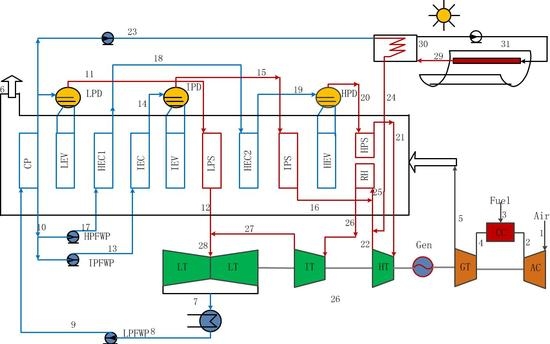
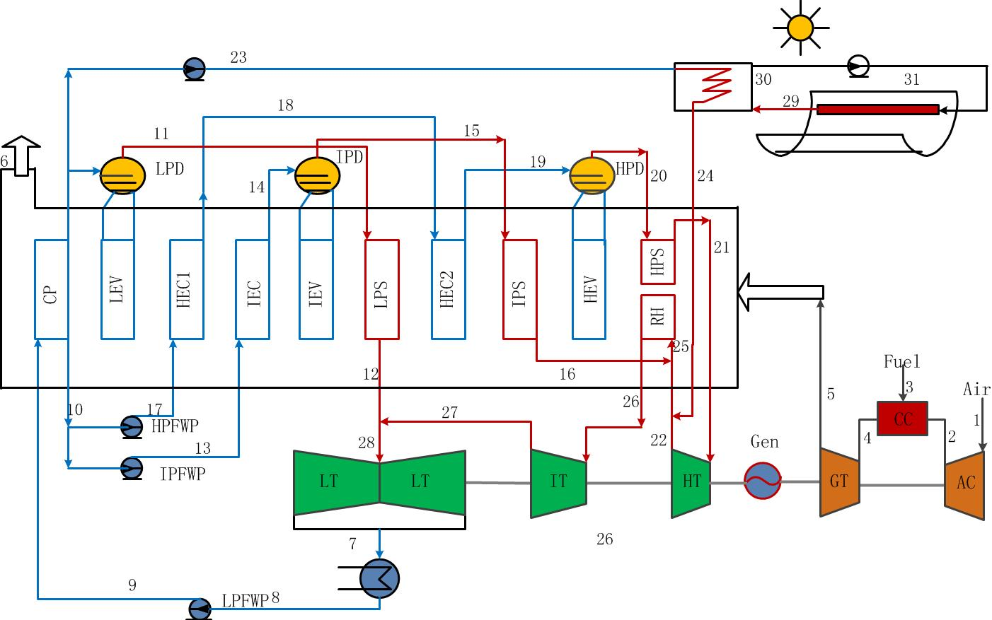
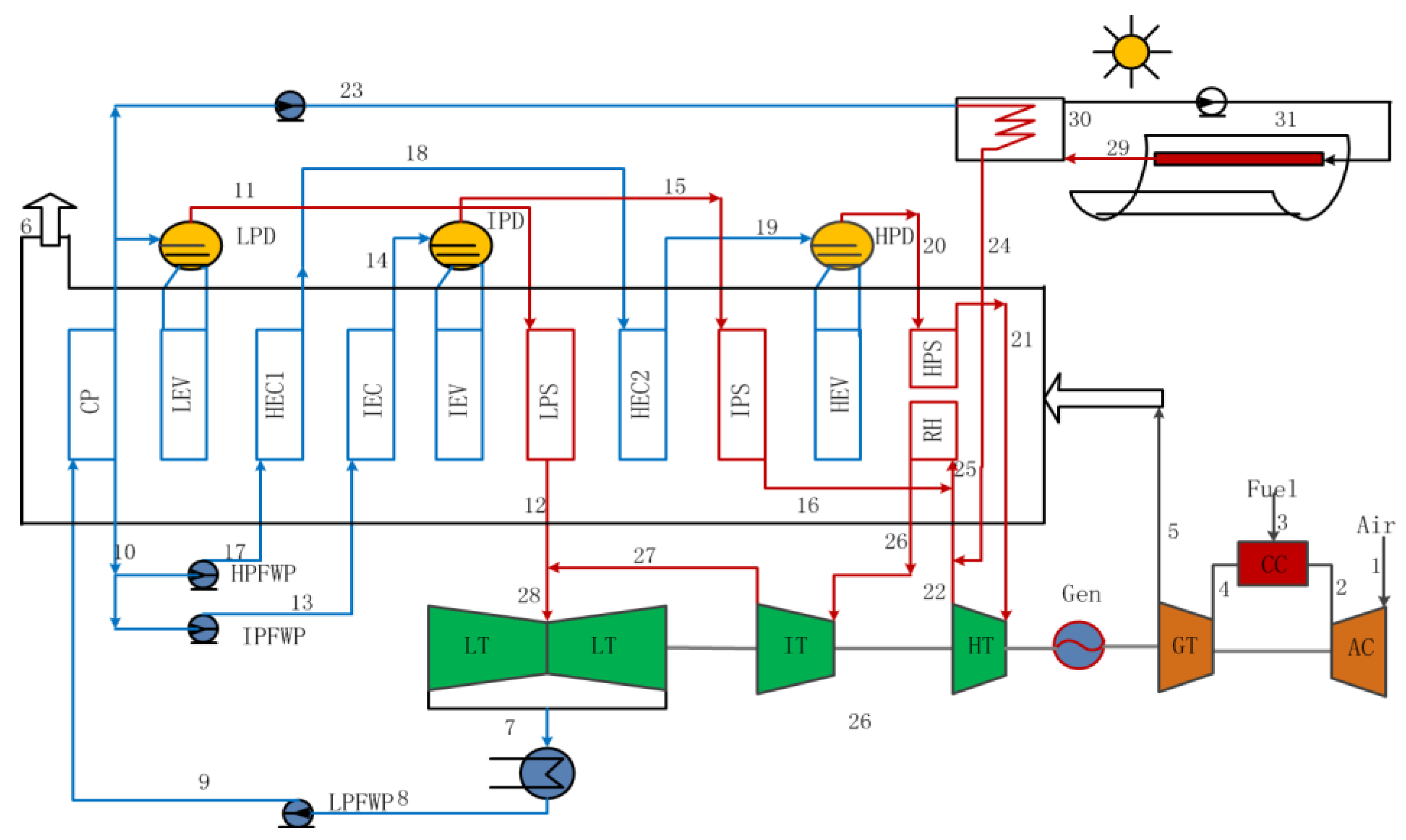
The ISCC system is based on a conventional CCPP which consists a gas turbine of V94.3, a three-pressure HRSG with reheat and solar field as shown in Figure 1. The pressured air burns with the nature gas in the combustion chamber (CC) then expands from the gas turbine to produce useful work. Meanwhile, the exhaust gas of the gas turbine is introduced to the HRSG to produce three different pressure level steams, i.e., the low-pressure steam (0.46 MPa), the intermediate-pressure steam (2.98 MPa) and the high-pressure steam (12.6 MPa). A part of feed water is injected to the solar field and heated to superheated steam (358.5 °C), which continues to get heat in the reheater with the exhaust steams of high-pressure steam turbine (361.3 °C) and the intermediate-pressure steam turbine (329.5 °C). Then, the mixed steams are introduced to the intermediate-pressure steam turbine.
Herein, the temperature of the superheated steam for solar field remains unchanged, while the mass flow rete can be changed with the absorbed solar energy. In this study, a part of feed water get heat in the PTCs during the sunny days, and reduced the fossil fuel consumption (power output constant); however, the proposed ISCC system operates as an ordinary CCPP during the gloomy period. It should be noted that the steam turbine is supposed to work at full load invariably, while the gas turbine may be lightly loaded with solar time.
2.2. Assumptions
Owing to the solar field coupled to the conventional CCPP, the parameters, like temperature and pressure, would have some impacts on system’s thermal efficiency, differ from that in the CCPP. Besides, we assume that the ambient temperature and pressure are 20 °C and 1 bar which means that the exergy value of inlet air is 0. In this paper, to simplify the analysis process, the simulation was further evaluated under the following conditions [27]:
- ■
- Air and exhaust of gas turbine were considered as ideal gases.
- ■
- The combustion was ideal and heat losses had been taken into account in the collectors and exchangers. Besides, all other components had no energy losses.
- ■
- The lower heating value (LHV) of fossil fuel (natural gas) was 49,015 kJ/kg.
- ■
- The ambient temperature and pressure are 20 °C and 1 bar.
3. Thermodynamic Analysis
The mathematical modeling of the proposed systems is presented in this portion. In addition, the advanced thermodynamic (energy, conventional exergy and advanced exergy analysis) analysis methods are considered.
3.1. Energy Analysis
The amount of obtained solar thermal can be estimated by the solar radiation intensity and the total area of PTCs, which can be expressed as:
where is the area of the collectors and stands for the number of collectors, DNI is the direct normal irradiance.
In the PTC, the solar thermal absorbed by the tube from the PTCs is defined as follow:
where the is the collector optical efficiency of PTC and it is further expressed as [21,29]:
where , , , , , and K are intercept factor, mirror reflectivity, glass transmissivity, solar absorptivity, solar absorptivity, clean factor, mirror utilization rate and incidence angle modifier, respectively.
Additionally, the energy efficiency of proposed system is defined as the ratio of net output work to the total energy input the system:
where and are the mass flow rate and the lower heating value of fossil fuel (nature gas), respectively.
Moreover, the efficiency of solar-to-electricity is applied to examine the behavior of the solar thermal conversion in ISCC and the equation is defined as follow:
where is the net output work of CCPP with the same amount of fossil fuel consumption.
3.2. Conventional Exergy Analysis
For an ideal process, the exergy input to the PTCs coming from the exergy of solar radiation. The maximum work () can be obtained from radiation, which is calculated with Petela’s formula [40]:
where is the ambition temperature, is the equivalent temperature of the sun as a black body (~5770 K).
The solar radiation exergy absorbed by the receiver tube and reflector is written as [41]:
The definition of exergy is expressed as the part of energy that can be completely converted to any other form of energy. Additionally, the exergy consists of four parts, i.e., the kinetic exergy, the potential exergy, the physical exergy () and the chemical exergy (). When the potential exergy and the kinetic exergy are ignored, the exergy balance equation can be defined as [42]:
where and can be obtained by the following equation [42]:
We can notice the above equation for estimating the chemical exergy of fossil fuel is puzzled. Therefore, another equation is presented as follows:
where is the coefficient of fossil fuel chemical exergy () to lower heating value (), herein, the coefficient of nature gas is 1.06. Additionally, the received exergy () by PTCs and absorbed exergy () by the absorber tube were defined as follow [4,9,29]:
where , and are the surface temperature of absorber tube, the ambient temperature and the solar surface temperature (5770 K), the and represent the heat transfer rate, MW, respectively.
3.3. Advanced Exergy Analysis
The exergy destruction () in main components of proposed system under non-ideal working conditions will be analyzed via the advanced exergy analysis method. The exergy balance equation for k-th components is defined [42]:
where, for an energy conversion system, the and are the “Fuel exergy” and the “Product exergy”, respectively.
In addition, the exergy efficiency () and the exergy destruction rate () are characterized as basic criteria for estimating the k-th component of ISCC, which can be defined as follow:
Moreover, for the overall system, when considering the exergy loss, the exergy balance equation can be expressed as [42]:
where, , and are the total exergy loss, total “Product exergy” and total “Fuel exergy” input the system.
In a complex energy conversion system, components interact with each other. Hence, the theory of dividing the exergy destruction into endogenous () and exogenous () parts, help us better estimating the exergy destruction caused by the internal/external factors in components. To estimate the endogenous exergy destruction of the k-th component, the k-th component was defined operating under real conditions, while other components of the proposed system operate under theoretical conditions (as shown in Table 1), the result is endogenous of the k-th component. Then, the exogenous exergy destruction can be estimated by the following equation [42]:
Additionally, the portion of exergy destruction, which can be minimized via improving working conditions, can be defined as avoidable exergy destruction (). However, the other portion that cannot be minimized is called unavoidable exergy destruction () [42]. The unavoidable parameters assumptions (as shown in Table 1) were used to calculate the unavoidable exergy destruction of the k-th component, which was defined by the experience and knowledge of the author on CCPP [42]:
4. Results and Discussion
4.1. Model Validation
In this paper, the models of conventional CCPP (Siemens, SGT5-4000F) and PTC were established on the thermodynamic software of Ebsilon® Professional (12.05, STEAG company, Essen, Germany). A great number of main parameters were chose to verify the simulation consequences of the proposed models. The main thermodynamic parameters of simulated values and designed values of CCPP are presented in Table 2. Herein, the results show a great accordance between the simulation values and the designed values (Siemens). After that, the PTC was added into the CCPP to heat part of feed water as shown in Figure 1.
The module of LS-2 was selected as the PTC in this study. It was uniformed on north-south and tracking the trajectory of the sun from east to west. The main parameters of PTCs are presented in Table 3. Moreover, the location of Shanghai, China (31.2° N, 121.4° E) was selected for this study. To evaluate the performance of the ISCC system during typical days, the hourly values of Shanghai were obtained from meteorological database, like the wind speed, the ambient temperature and the DNI. The aperture area of PTC is 786 m2 with 280 Loops. The thermal efficiency in this study has been taken from previous studies [12]. The solar irradiation has selected to be 800 W/m2, and the incident angle () is 0°, in order emphasis to be given in the thermal and exergy analysis [41]. The PTCs heat the HTF (Heat Transfer Fluid) from 315.9 °C to 395.0 °C, and the pressure drops from 5.0 MPa to 3.5 MPa. In addition, the heat loss of pipeline is 20 W/m2.
4.2. Results of Energy and Conventional Exergy Analysis
The ISCC system has double energy inputs (i.e., the solar energy and nature gas). The performances of solar field and overall plant are affected by the solar irradiation intensity. Therefore, a parametric study is conducted to examine the performance of both solar field and overall proposed system on four typical days (21st March, 22nd June, 23rd September and 22nd December).
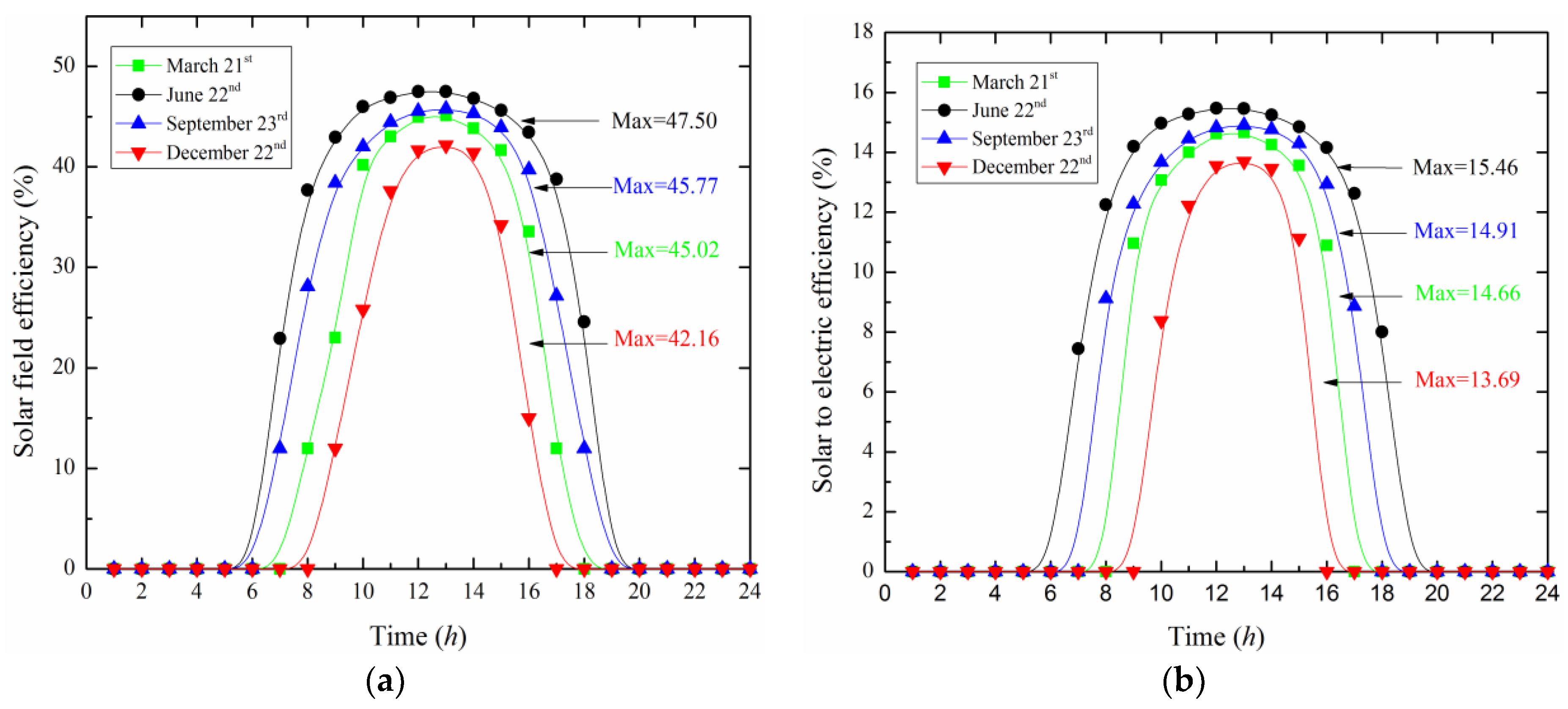
The solar field efficiency and solar-to-electric efficiency depend on the irradiation intensity and are shown in Figure 2. It can be observed that as the solar irradiation intensity raises, the efficiency of solar field increase to 42.16% in winter and 47.5% in summer at noon time (13:00 p.m.). Besides, the solar-to-electric efficiency reaches to 13.69% in winter and 15.46% in summer. Herein, it should be noticed that the temperature of superheated steam for solar field is constant (358.5 °C); however the mass flow rate of the superheated steam can vary with the irradiation intensity.
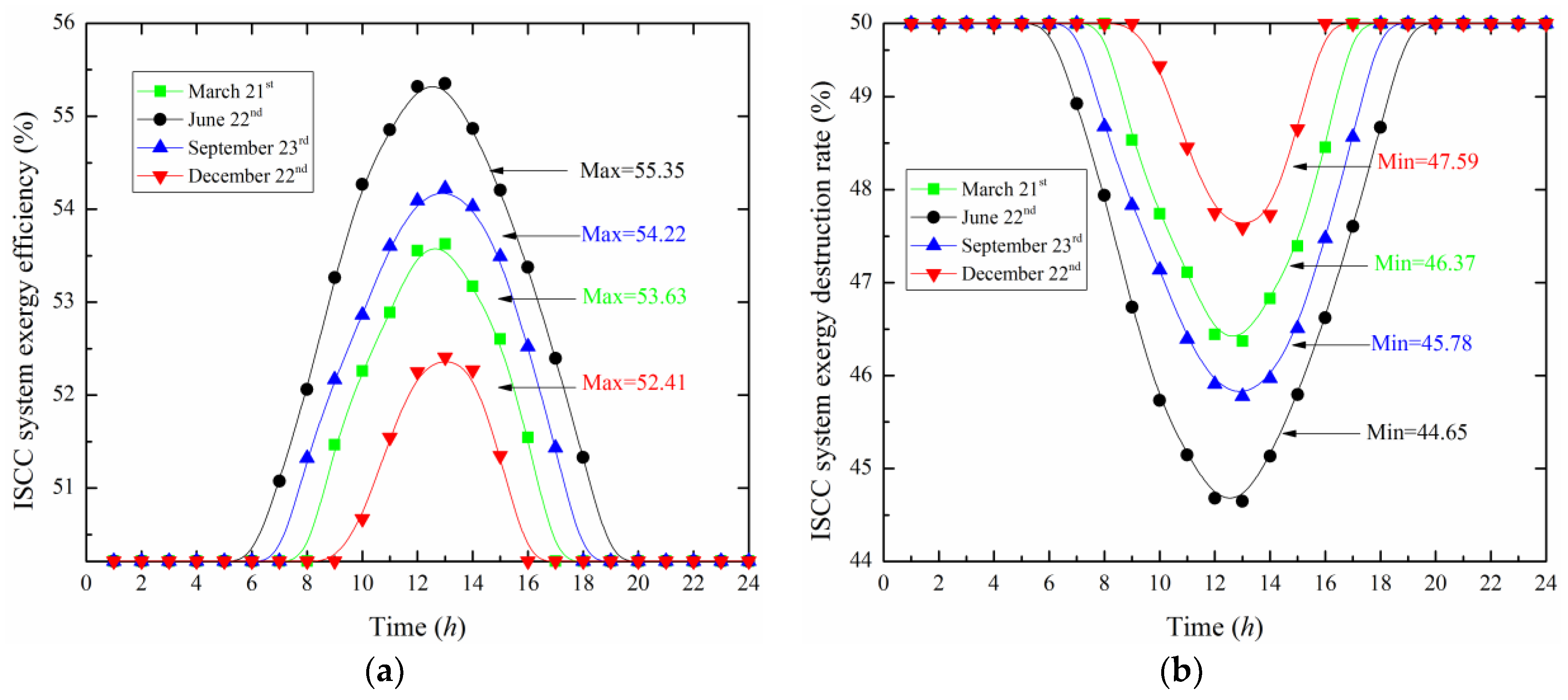
To further assess the exergy performance of proposed system on the four typical days, the both results of exergy efficiency and exergy destruction rate of proposed ISCC system are demonstrated in Figure 3. The results reveal that as the solar irradiation intensity increases, the overall system exergy efficiency increases. Additionally, the overall system exergy efficiency can reach from 50.21% to 55.35% in summer and from 50.21% to 52.41% in winter. On contrast, the exergy destruction rate of overall system drops from 49.79% to 44.65% in summer and drops from 49.79% to 47.59% in winter. It should be noticed that the exergy efficiency value of 50.21% and the exergy destruction rate of 49.79% are the standard values of conventional CCPP (without solar field).
Indeed, the fuel-based efficiencies only consider the portion of energy received from fossil fuels. When the proposed system operates under the fuel-saving conditions, it means the power output constant and the fuel consumption varies with the irradiation intensity. In addition, the solar energy inputs the system will reduce the fuel consumption (output constant), thus improves the energy efficiency but drops the exergy destruction rate.
4.3. Results of Advanced Exergy Analysis
The calculated results of the exergy destruction, exergy efficiency and exergy destruction rate of main components in proposed ISCC system within a typical day (22nd June) were shown in Figure 4, Figure 5, Figure 6, Figure 7, Figure 8 and Figure 9. Additionally, in order to better estimate the potentials for performance enhancement of the components, the exergy destruction of components was divided into unavoidable/avoidable and exogenous/endogenous parts.
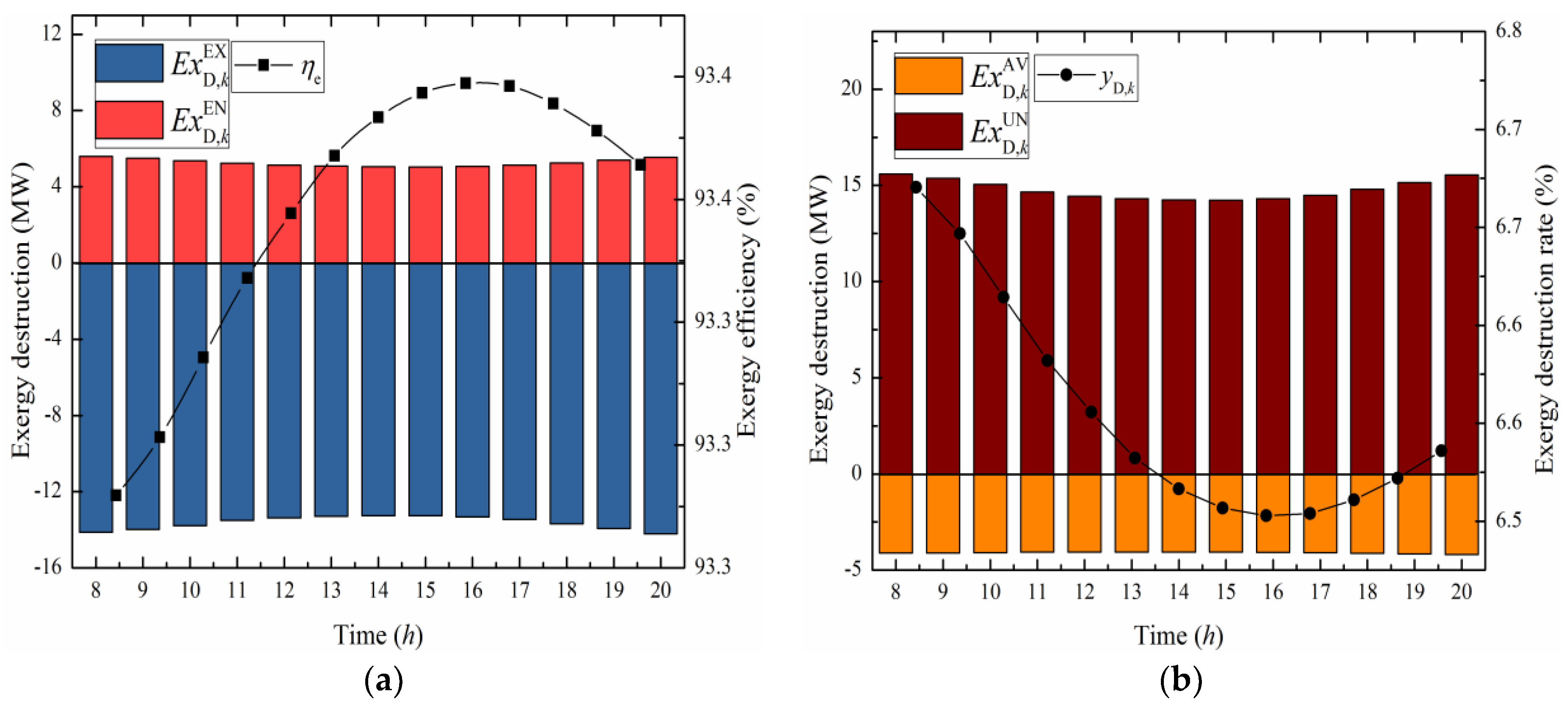
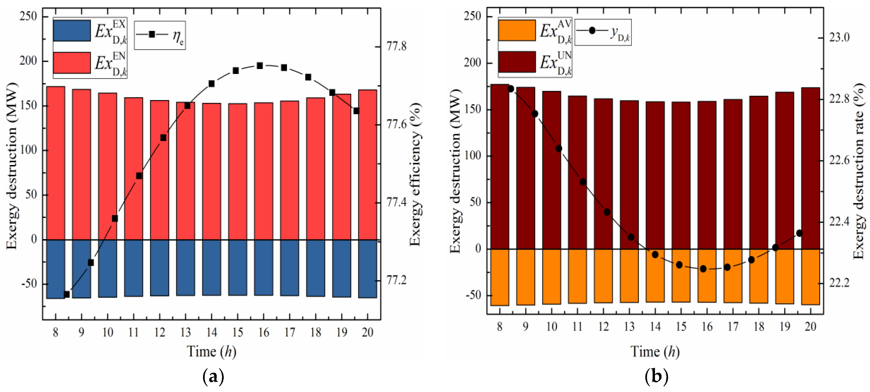
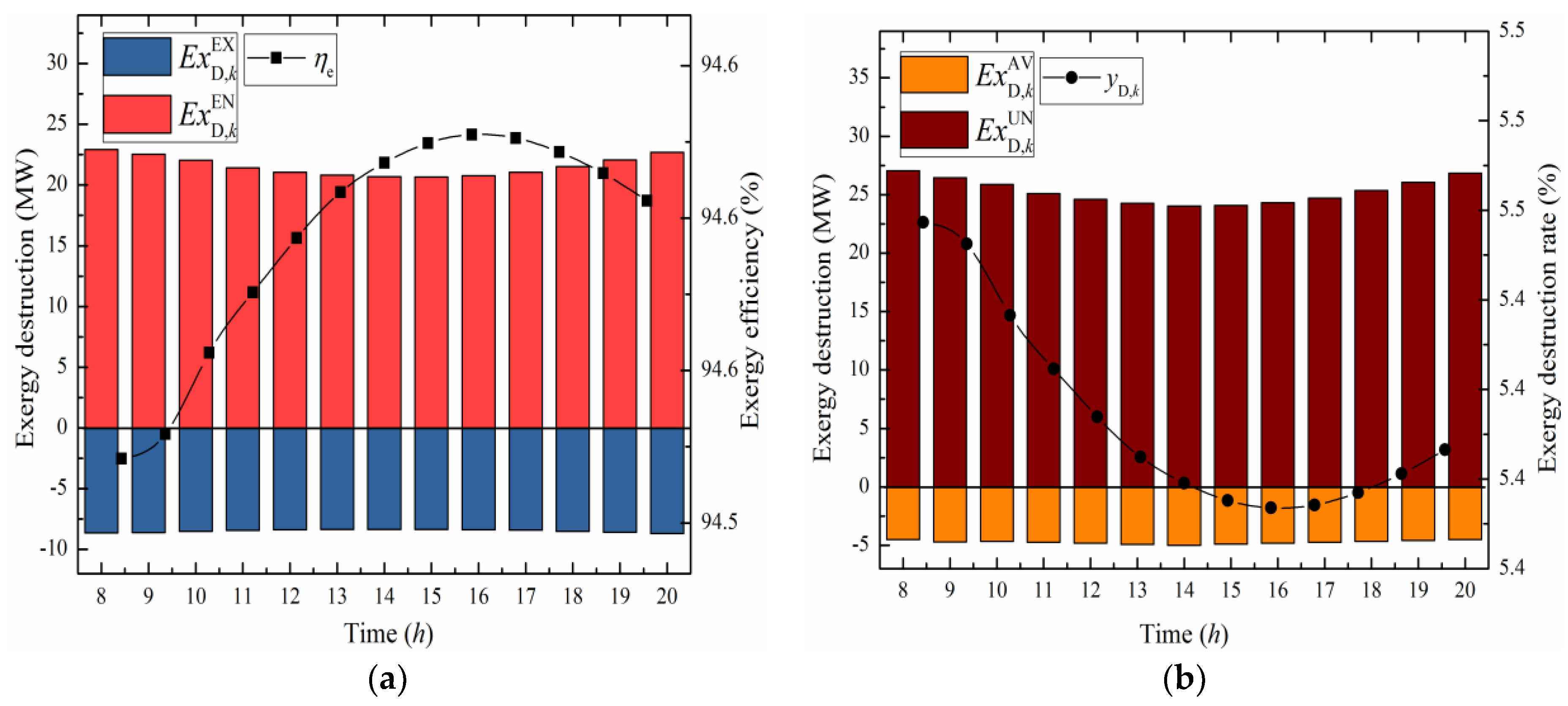
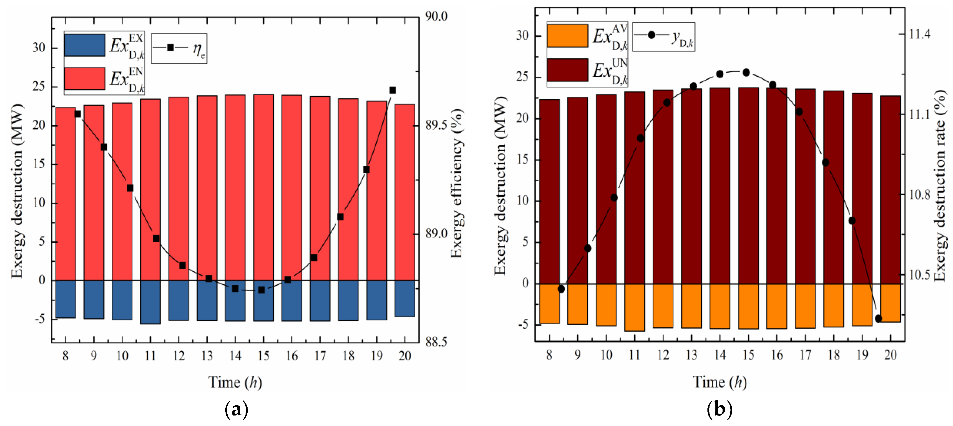
In addition, the unavoidable/avoidable and exogenous/endogenous exergy destruction of Brayton cycle components (compressor, CC and gas turbine) are shown in Figure 4, Figure 5 and Figure 6. It can be observed that with the increase of solar energy input to the ISCC system, the exergy destruction (unavoidable/avoidable and exogenous/endogenous) of Brayton cycle components decreases. For instance, the exergy destruction of compressor decreases from 19.71 MW at 8:00 a.m. to 18.29 MW at 15:00 p.m. Meanwhile, the exergy destruction of CC drops from 237.82 MW to 214.99 MW, and the exergy destruction of gas turbine reduces from 31.56 MW to 29.00 MW. Additionally, the unavoidable/avoidable and exogenous/endogenous exergy destruction of gas turbine also decreases slightly. Since the reduced fuel consumption decreases both the inefficiency and inherent irreversibility then reduces the exergy destruction of gas turbine. Obviously, the reduction of exergy destruction can lead to the improvement of the overall plant performance. Moreover, it has been also observed that the CC and gas turbine have a higher percentage of endogenous exergy destruction. It is separate from the external factors and related to the irreversible losses. Besides, the compressor has a large proportion of exogenous exergy destruction which is associated with the operation conditions (external factors) and it can be influenced between components.
Furthermore, the results of exergy efficiency and exergy destruction rate of Brayton cycle components (compressor, CC and gas turbine) variation with time are also shown in Figure 4, Figure 5 and Figure 6. It can be obtained that the exergy efficiency rises with the solar irradiation intensity. Moreover, the compressor, CC and gas turbine have the largest exergy efficiency values of 93.45%, 77.75% and 94.61% at 16:00 p.m. As previously discussed, this is due to the fuel-saving condition can reduce a part of fuel consumption then minimizes the exergy destruction. However, the exergy destruction rate has an opposite trend with that of exergy efficiency. Thus, the compressor, CC and gas turbine have the lowest exergy destruction rate of 6.55%, 22.25% and 5.39%, respectively.
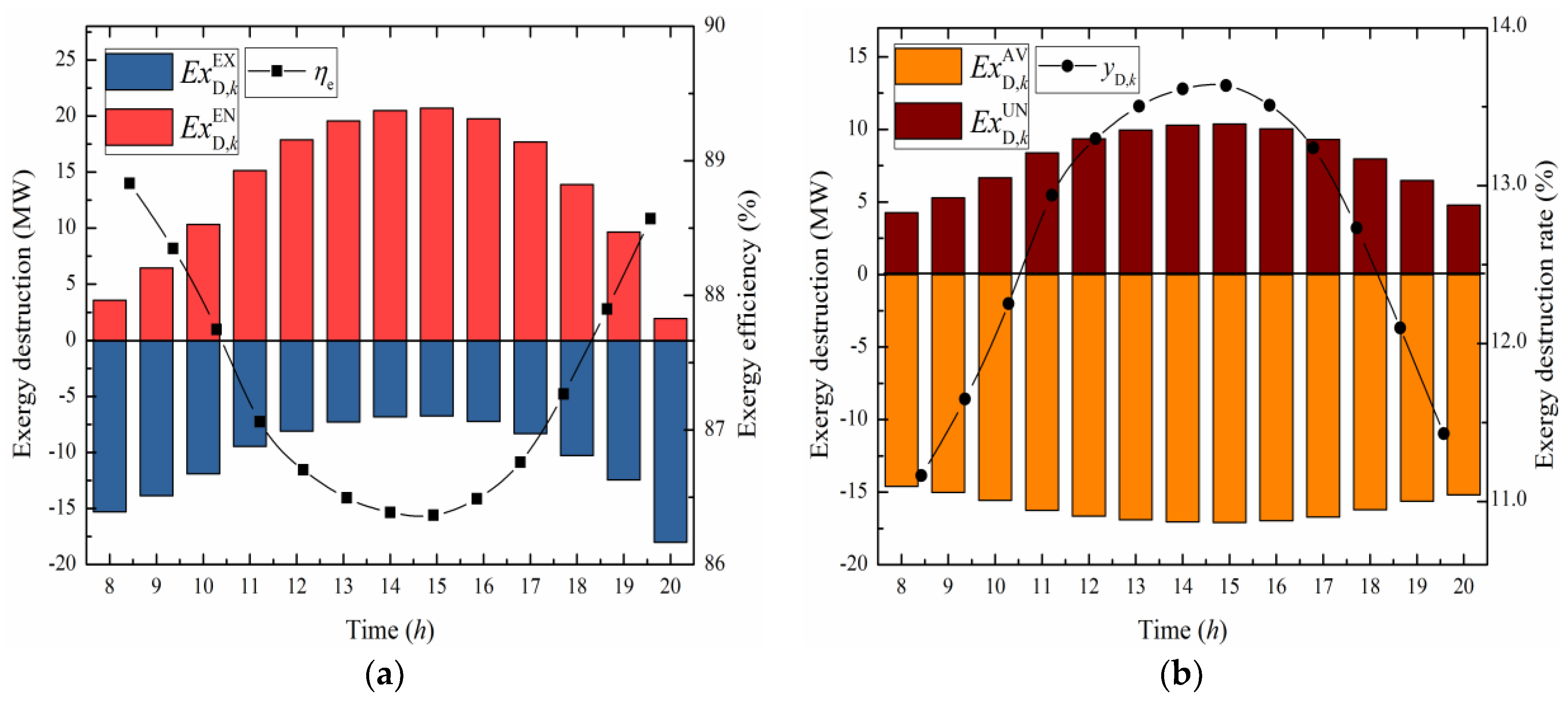
Similar to previous figures, results of the exergy destruction, the exergy efficiency and the exergy destruction rate for Rankine cycle components (HRSG, steam turbines and solar field) variation with time are displayed in Figure 7, Figure 8 and Figure 9. It has been seen that the exergy destruction (unavoidable/avoidable and exogenous/endogenous) of Rankine cycle components raise with the solar irradiation intensity, which means the irreversible losses caused by independent of external factors in Rankine cycle components increase with the solar irradiation intensity. For instance, the exergy destruction of HRSG rises from 27.14 MW at 8:00 a.m. to 29.19 MW at 15:00 p.m. Meanwhile, the exergy destruction of steam turbines extended from 18.85 MW to 27.45 MW and the exergy destruction of solar field has a large expanded from 14.55 MW to 58.03 MW.
Moreover, the exergy efficiency and exergy destruction rate of HRSG and steam turbines variation with time are also shown in Figure 7 and Figure 8. It can also be observed that the exergy destruction rate rises with the solar irradiation intensity. Additionally, the HRSG and steam turbines have largest exergy destruction rate of 11.26% and 13.63% at 15:00 p.m. Since the solar energy integrated into the HRSG of Rankine cycle is converted into electricity improving the thermodynamic efficiency of proposed system. However, the HRSG and steam turbines show lowest exergy efficiency values of 88.74% and 86.37%, respectively.
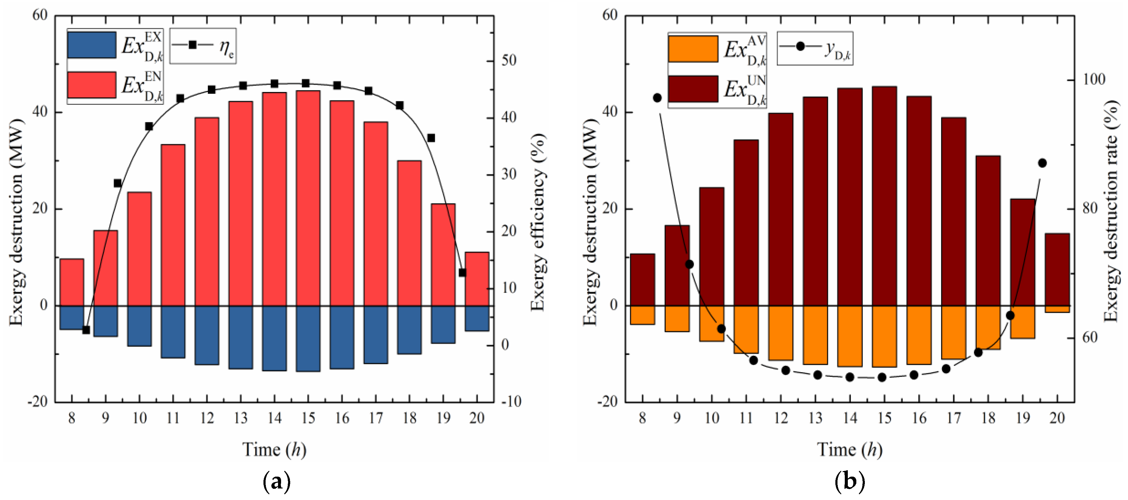
The results of the exergy destruction, the exergy destruction rate and the exergy efficiency for solar field variation with time are illustrated in Figure 9. It can be obtained that the endogenous portion always shows a larger value than the exogenous one. For the reason that the energy losses (internal factors) in the large numbers of exchangers and the heat transfer process occurred in the vast area of the solar field have a dominant role in exergy destruction. Similarly, the portion of unavoidable exergy destruction which cannot be minimized under the current technical or economic restrictions is larger than the avoidable one.
In addition, the exergy destruction value of solar field rises with the solar irradiation intensity, and the solar field appears a largest exergy efficiency value of 46.06% at 15:00 p.m., at the same time, it shows a lowest exergy destruction rate of 53.88%. However, as the solar energy entering the system, the exergy efficiency will increase from 50.21% to 55.35%, thus further improving the performance of proposed ISCC system.
Results can be acquired from the above perspectives. In particular, designers should focus first on the CC and the steam turbines. Since the CC and the steam turbines present larger avoidable exergy destruction than other components, thus the two components are more important by technical modifications. Moreover, all components except the compressor have higher endogenous exergy destruction, which indicates the most irreversible exergy destruction is produced by the component itself (topology structure). It should be noticed that the calculated unavoidable/avoidable and exogenous/endogenous exergy destruction values are positive, which reveals that the performance of components enhances with the strengthening of other system components.
5. Conclusions
In this paper, the variation performance of solar field and overall ISCC system were analyzed through energy and conventional exergy analysis methods. Additionally, the advanced exergy method was aimed at the main components of ISCC by dividing the exergy destruction into unavoidable/avoidable and exogenous/endogenous parts, which can better estimate the real prospective of the components in the proposed system. It can be observed that the advanced exergy analysis provides useful and more reliable information not attainable from the conventional exergy analysis. Moreover, the variation performances of main components were hourly analyzed within a typical day. From the obtained results, the conclusions of this research are as follows:
- ■
- As the solar irradiation intensity rises, the solar field efficiency reached to 42.16% in winter and 47.5% in summer at noon. The solar-to-electric efficiency got to 13.69% in winter and 15.46% in summer. For overall plant, the exergy efficiency reached from 50.21% to 55.35% in summer and from 50.21% to 52.41% in winter. In contrast, the exergy destruction rate dropped from 49.79% to 44.65% in summer and decreased from 49.79% to 47.59% in winter.
- ■
- For Brayton cycle components, with the increased of solar energy input to the ISCC system, the exergy destruction of Brayton cycle components decreased. The exergy destruction of compressor dropped from 19.71 MW to 18.29 MW at 8:00~15:00. Meanwhile, the exergy destruction of CC and gas turbine decreased from 237.82 MW to 214.99 MW and from 31.56 MW to 29.00 MW, respectively. Furthermore, the compressor, CC and gas turbine had the largest exergy efficiency values of 93.45%, 77.75% and 94.61% at 16:00 p.m. However, they showed lowest exergy destruction rate of 6.55%, 22.25% and 5.39%, respectively
- ■
- For Rankine cycle components, the exergy destruction increased with the solar irradiation intensity, the exergy destruction of HRSG raised from 27.14 MW to 29.19 MW at 8:00~15:00. Meanwhile, the exergy destruction of steam turbines enlarged from 18.85 MW to 27.45 MW and the exergy destruction of solar field had a large extended from 14.55 MW to 58.03 MW. Additionally, the HRSG and the steam turbines had largest exergy destruction rate of 11.26% and 13.63% at 15:00 p.m. However, they showed lowest exergy efficiency values of 88.74% and 86.37%, respectively. The solar field had a largest exergy efficiency value of 46.06% at 15:00 p.m.; at the same time, it showed a lowest exergy destruction rate of 53.88%.
Author Contributions
S.W. conceived the project, proposed the optimization model and wrote the manuscript; Z.F. conceived and designed the simulations; G.Z. and T.Z. performed the data analysis.
Funding
This research was funded by [Fundamental Research Funds for the Central Universities] grant number [2018QN035]. And [Natural Science Foundation of Beijing] grant number [3162030].
Conflicts of Interest
The authors declare no conflict of interest.
Nomenclature
| Abbreviations | |
| AC | Air Compressor |
| CC | Combustion Chamber |
| CCPP | Combined Cycle Power Plant |
| CPH | Condensate Preheater |
| DNI | Direct Normal Irradiance |
| Gen | Generator |
| GT | Gas Turbine |
| HEC | High Pressure Economizer |
| HEV | High Pressure Evaporator |
| HP | High Pressure |
| HPFWP | High Pressure Feed Water Pump |
| HRSG | Heat Recovery Steam Generator |
| HSH | High Pressure Superheater |
| HT | High Pressure Steam Turbine |
| HTF | Heat Transfer Fluid |
| IEC | Intermediate Pressure Economizer |
| IEV | Intermediate Pressure Evaporator |
| IP | Intermediate Pressure |
| IPFWP | Intermediate Pressure Feed Water Pump |
| ISCC | Integrated Solar Combined Cycle |
| ISH | Intermediate Pressure Superheater |
| IT | Intermediate Pressure Steam Turbine |
| LEV | Low Pressure Evaporator |
| LHV | Lower Heating Value |
| LP | Low Pressure |
| LPFWP | Low Pressure Feed Water Pump |
| LSH | Low Pressure Superheater |
| LT | Low Pressure Steam Turbine |
| PTC | Parabolic Trough Collector |
| REH | Reheater |
| Exergy of a stream | |
| Physical exergy | |
| Chemical exergy | |
| Exergy received by the collector | |
| Exergy absorbed by the absorber | |
| Exergy destruction of kth component | |
| Fuel exergy of kth component | |
| Product exergy of kth component | |
| Exergy loss in the system | |
| Endogenous exergy destruction of kth component | |
| Exogenous exergy destruction of kth component | |
| Energy received by the collector | |
| Energy absorbed by the absorber | |
| Incidence angle modifier | |
| Ambient temperature | |
| Solar surface temperature | |
| Collectors surface temperature | |
| Greek Symbols | |
| Intercept factor | |
| Mirror reflectivity | |
| Glass transmissivity | |
| Solar absorptivity | |
| Clean factor | |
| Mirror utilization rate | |
| Exergy destruction rate | |
References
- Zhong, W.; Chen, X.; Zhou, Y.; Wu, Y.; López, C. Optimization of a solar aided coal-fired combined heat and power plant based on changeable integrate mode under different solar irradiance. Sol. Energy 2017, 150, 437–446. [Google Scholar] [CrossRef]
- International Energy Agency (IEA). I.E.A., Concentrating Solar Power Roadmap; IEA: Paris, France, 2010. [Google Scholar]
- Behar, O. A novel hybrid solar preheating gas turbine. Energy Convers. Manag. 2018, 158, 120–132. [Google Scholar] [CrossRef]
- Xu, C.; Wang, Z.; Li, X.; Sun, F. Energy and exergy analysis of solar power tower plants. Appl. Therm. Eng. 2011, 31, 3904–3913. [Google Scholar] [CrossRef]
- Kabir, E.; Kumar, P.; Kumar, S.; Adelodun, A.A.; Kim, K.-H. Solar energy: Potential and future prospects. Renew. Sustain. Energy Rev. 2018, 82, 894–900. [Google Scholar] [CrossRef]
- Zhai, R.; Peng, P.; Yang, Y.; Zhao, M. Optimization study of integration strategies in solar aided coal-fired power generation system. Renew. Energy 2014, 68, 80–86. [Google Scholar] [CrossRef]
- Zhu, Y.; Zhai, R.; Zhao, M.; Yang, Y.; Yan, Q. Evaluation methods of solar contribution in solar aided coal-fired power generation system. Energy Convers. Manag. 2015, 102, 209–216. [Google Scholar] [CrossRef]
- Mabrouk, M.T.; Kheiri, A.; Feidt, M. A Systematic procedure to optimize Integrated Solar Combined Cycle power plants (ISCCs). Appl. Therm. Eng. 2018, 136, 97–107. [Google Scholar] [CrossRef]
- Baghernejad, A.; Yaghoubi, M. Exergy analysis of an integrated solar combined cycle system. Renew. Energy 2010, 35, 2157–2164. [Google Scholar] [CrossRef]
- Zhu, Y.; Zhai, R.; Peng, H.; Yang, Y. Exergy destruction analysis of solar tower aided coal-fired power generation system using exergy and advanced exergetic methods. Appl. Therm. Eng. 2016, 108, 339–346. [Google Scholar] [CrossRef]
- Wang, Y.; Xu, J.; Chen, Z.; Cao, H.; Zhang, B. Technical and economical optimization for a typical solar hybrid coal-fired power plant in China. Appl. Therm. Eng. 2017, 115, 549–557. [Google Scholar] [CrossRef]
- Wang, S.; Fu, Z.; Sajid, S.; Zhang, T.; Zhang, G. Thermodynamic and Economic Analysis of an Integrated Solar Combined Cycle System. Entropy 2018, 20, 313. [Google Scholar] [CrossRef]
- Alqahtani, B.J.; Patiño-Echeverri, D. Integrated Solar Combined Cycle Power Plants: Paving the way for thermal solar. Appl. Energy 2016, 169, 927–936. [Google Scholar] [CrossRef] [Green Version]
- Saghafifar, M.; Gadalla, M. Thermo-economic analysis of conventional combined cycle hybridization: United Arab Emirates case study. Energy Convers. Manag. 2016, 111, 358–374. [Google Scholar] [CrossRef]
- Aldali, Y.; Morad, K. Numerial simulation of the integrated solar/North Benghazi combined power plant. Appl. Therm. Eng. 2016, 108, 785–792. [Google Scholar] [CrossRef]
- Bellos, E.; Tzivanidis, C.; Antonopoulos, K.A. Parametric analysis and optimization of a solar assisted gas turbine. Energy Convers. Manag. 2017, 139, 151–165. [Google Scholar] [CrossRef]
- Najjar, Y.S.H.; Abubaker, A.M. Thermoeconomic analysis and optimization of a novel inlet air cooling system with gas turbine engines using cascaded waste-heat recovery. Energy 2017, 128, 421–434. [Google Scholar] [CrossRef]
- Popov, D. Innovative solar augmentation of gas turbine combined cycle plants. Appl. Therm. Eng. 2014, 64, 40–50. [Google Scholar] [CrossRef]
- Saghafifar, M.; Gadalla, M. Innovative inlet air cooling technology for gas turbine power plants using integrated solid desiccant and Maisotsenko cooler. Energy 2015, 87, 663–677. [Google Scholar] [CrossRef]
- Kelly, B.; Herrmann, U.; Hale, M.J. Optimization studies for integrated solar combined cycle systems. In Proceedings of the Solar Forum 2010 Solar Energy: The Power to Choose, Washington, DC, USA, 21–25 April 2010. [Google Scholar]
- Li, Y.; Yang, Y. Thermodynamic analysis of a novel integrated solar combined cycle. Appl. Energy 2014, 122, 133–142. [Google Scholar] [CrossRef]
- Montes, M.J.; Rovira, A.; Muñoz, M.; Martínez-Val, J.M. Performance analysis of an Integrated Solar Combined Cycle using Direct Steam Generation in parabolic trough collectors. Appl. Energy 2011, 88, 3228–3238. [Google Scholar] [CrossRef]
- Liu, Q.; Bai, Z.; Wang, X.; Lei, J.; Jin, H. Investigation of thermodynamic performances for two solar-biomass hybrid combined cycle power generation systems. Energy Convers. Manag. 2016, 122, 252–262. [Google Scholar] [CrossRef]
- Zhu, G.; Neises, T.; Turchi, C.; Bedilion, R. Thermodynamic evaluation of solar integration into a natural gas combined cycle power plant. Renew. Energy 2015, 74, 815–824. [Google Scholar] [CrossRef] [Green Version]
- Mokheimer, E.M.A.; Dabwan, Y.N.; Habib, M.A.; Said, S.A.M.; Al-Sulaiman, F.A. Development and assessment of integrating parabolic trough collectors with steam generation side of gas turbine cogeneration systems in Saudi Arabia. Appl. Energy 2015, 141, 131–142. [Google Scholar] [CrossRef]
- Rovira, A.; Montes, M.J.; Varela, F.; Gil, M. Comparison of Heat Transfer Fluid and Direct Steam Generation technologies for Integrated Solar Combined Cycles. Appl. Therm. Eng. 2013, 52, 264–274. [Google Scholar] [CrossRef]
- Mohammadi Khoshkar Vandani, A.; Joda, F.; Bozorgmehry Boozarjomehry, R. Exergic, economic and environmental impacts of natural gas and diesel in operation of combined cycle power plants. Energy Convers. Manag. 2016, 109, 103–112. [Google Scholar] [CrossRef]
- Al-Sulaiman, F.A. Exergy analysis of parabolic trough solar collectors integrated with combined steam and organic Rankine cycles. Energy Convers. Manag. 2014, 77, 441–449. [Google Scholar] [CrossRef]
- Adibhatla, S.; Kaushik, S.C. Energy, exergy and economic (3E) analysis of integrated solar direct steam generation combined cycle power plant. Sustain. Energy Technol. Assess. 2017, 20, 88–97. [Google Scholar] [CrossRef]
- Baghernejad, A.; Yaghoubi, M. Exergoeconomic analysis and optimization of an Integrated Solar Combined Cycle System (ISCCS) using genetic algorithm. Energy Convers. Manag. 2011, 52, 2193–2203. [Google Scholar] [CrossRef]
- Zare, V.; Hasanzadeh, M. Energy and exergy analysis of a closed Brayton cycle-based combined cycle for solar power tower plants. Energy Convers. Manag. 2016, 128, 227–237. [Google Scholar] [CrossRef]
- Sorgulu, F.; Dincer, I. Thermodynamic analyses of a solar-based combined cycle integrated with electrolyzer for hydrogen production. Int. J. Hydrogen Energy 2018, 43, 1047–1059. [Google Scholar] [CrossRef]
- Boyaghchi, F.A.; Molaie, H. Sensitivity analysis of exergy destruction in a real combined cycle power plant based on advanced exergy method. Energy Convers. Manag. 2015, 99, 374–386. [Google Scholar] [CrossRef]
- Tsatsaronis, G. Strengths and limitations of exergy analysis. In Thermodynamic Optimization of Complex Energy Systems; Springer: Berlin, Germany, 1999; pp. 93–100. [Google Scholar]
- Wang, L.; Yang, Y.; Morosuk, T.; Tsatsaronis, G. Advanced Thermodynamic Analysis and Evaluation of a Supercritical Power Plant. Energies 2012, 5, 1850–1863. [Google Scholar] [CrossRef] [Green Version]
- Açıkkalp, E.; Aras, H.; Hepbasli, A. Advanced exergy analysis of an electricity-generating facility using natural gas. Energy Convers. Manag. 2014, 82, 146–153. [Google Scholar] [CrossRef]
- Petrakopoulou, F.; Tsatsaronis, G.; Morosuk, T.; Carassai, A. Conventional and advanced exergetic analyses applied to a combined cycle power plant. Energy 2012, 41, 146–152. [Google Scholar] [CrossRef]
- Montes, M.J.; Abánades, A.; Martínez-Val, J.M.; Valdés, M. Solar multiple optimization for a solar-only thermal power plant, using oil as heat transfer fluid in the parabolic trough collectors. Sol. Energy 2009, 83, 2165–2176. [Google Scholar] [CrossRef] [Green Version]
- Bellos, E.; Tzivanidis, C.; Belessiotis, V. Daily performance of parabolic trough solar collectors. Sol. Energy 2017, 158, 663–678. [Google Scholar] [CrossRef]
- Petela, R. Exergy of undiluted thermal radiation. Sol. Energy 2003, 74, 469–488. [Google Scholar] [CrossRef]
- Akbarzadeh, S.; Valipour, M.S. Heat transfer enhancement in parabolic trough collectors: A comprehensive review. Renew. Sustain. Energy Rev. 2018, 92, 198–218. [Google Scholar] [CrossRef]
- Boyaghchi, F.A.; Molaie, H. Advanced exergy and environmental analyses and multi objective optimization of a real combined cycle power plant with supplementary firing using evolutionary algorithm. Energy 2015, 93, 2267–2279. [Google Scholar] [CrossRef]
- Zhai, R.; Li, C.; Qi, J.; Yang, Y. Thermodynamic analysis of CO2 capture by calcium looping process driven by coal and concentrated solar power. Energy Convers. Manag. 2016, 117, 251–263. [Google Scholar] [CrossRef]
- Bellos, E.; Tzivanidis, C. A detailed exergetic analysis of parabolic trough collectors. Energy Convers. Manag. 2017, 149, 275–292. [Google Scholar] [CrossRef]
Figure 1.
The schematic of ISCC. (LPD: Low Pressure Drum; IPD: Intermediate Pressure Drum; HPD: High Pressure Drum; CP: Condensate Preheater; LEV: Low Pressure Evaporator; HEC: High Pressure Economizer; IEC: Intermediate Pressure Economizer; IEV: Intermediate Pressure Evaporator; LPS: Low Pressure Superheater; IPS: Intermediate Pressure Superheater; HEV: High Pressure Evaporator; HPS: High Pressure Superheater; RH: Reheater; HPFWP: High Pressure Feed Water Pump; IPFWP: Intermediate Pressure Feed Water Pump; LPFWP: Low Pressure Feed Water Pump; LT: Low Pressure Steam Turbine; IT: Intermediate Pressure Steam Turbine; HT: High Pressure Steam Turbine; GEN: Generator; GT: Gas Turbine; CC: Combustion Chamber; AC: Air Compressor).

Figure 2.
The performance of solar field variation with time. (a) The solar field efficiency variation with time. (b) The solar-to-electric efficiency variation with time.
Figure 2.
The performance of solar field variation with time. (a) The solar field efficiency variation with time. (b) The solar-to-electric efficiency variation with time.

Figure 3.
The performance of overall system variation with time. (a) The efficiency of ISCC system exergy variation with time. (b) The overall system exergy destruction rate variation with time.
Figure 3.
The performance of overall system variation with time. (a) The efficiency of ISCC system exergy variation with time. (b) The overall system exergy destruction rate variation with time.

Figure 4.
The exergy destruction, exergy efficiency and exergy destruction rate of compressor variation with time. (a) The endogenous/exogenous exergy destruction and exergy efficiency variation with time. (b) The avoidable/unavoidable exergy destruction and exergy destruction rate variation with time.

Figure 5.
The exergy destruction, exergy efficiency and exergy destruction rate of CC variation with time. (a) The endogenous/exogenous exergy destruction and exergy efficiency variation with time. (b) The avoidable/unavoidable exergy destruction and exergy destruction rate variation with time.
Figure 5.
The exergy destruction, exergy efficiency and exergy destruction rate of CC variation with time. (a) The endogenous/exogenous exergy destruction and exergy efficiency variation with time. (b) The avoidable/unavoidable exergy destruction and exergy destruction rate variation with time.

Figure 6.
The exergy destruction, exergy efficiency and exergy destruction rate of gas turbine variation with time. (a) The endogenous/exogenous exergy destruction and exergy efficiency variation with time. (b) The avoidable/unavoidable exergy destruction and exergy destruction rate variation with time.

Figure 7.
The exergy destruction, exergy efficiency and exergy destruction rate of HRSG variation with time. (a) The endogenous/exogenous exergy destruction and exergy efficiency variation with time. (b) The avoidable/unavoidable exergy destruction and exergy destruction rate variation with time.
Figure 7.
The exergy destruction, exergy efficiency and exergy destruction rate of HRSG variation with time. (a) The endogenous/exogenous exergy destruction and exergy efficiency variation with time. (b) The avoidable/unavoidable exergy destruction and exergy destruction rate variation with time.

Figure 8.
The exergy destruction, exergy efficiency and exergy destruction rate of steam turbines variation with time. (a) The endogenous/exogenous exergy destruction and exergy efficiency variation with time. (b) The avoidable/unavoidable exergy destruction and exergy destruction rate variation with time.

Figure 9.
The exergy destruction, exergy efficiency and exergy destruction rate of solar field variation with time. (a) The endogenous/exogenous exergy destruction and exergy efficiency variation with time. (b) The avoidable/unavoidable exergy destruction and exergy destruction rate variation with time.


Table 1.
Parameters for advanced thermodynamic analysis.
| Component, k | Real Parameters | Theoretical Parameters [42] | Unavoidable Parameters |
|---|---|---|---|
| Compressor | |||
| CC | |||
| Gas turbine | |||
| Steam Turbines | |||
| Pumps | |||
| Exchangers | |||
| PTC |
Table 2.
Main parameters of Siemens.
| Parameters | Siemens | Simulation | Units |
|---|---|---|---|
| Capability | 390 | 390 | MW |
| High-pressure steam Reheat steam Low-pressure steam | 12.5/566/72.6 2.99/551/85.6 0.45/239/12.3 | 12.6/567/73.8 2.91/551/86.7 0.46/239.9/12.9 | MPa/°C/kgs−1 MPa/°C/kgs−1 MPa/°C/kgs−1 |
| Gas turbine exhaust | 590/643 | 590.6/646 | °C/kgs−1 |
| Exhaust gas temperature | 90 | 90.9 | °C |
| Ambient temperature | 20 | 20 | °C |
Table 3.
Main parameters of parabolic trough solar collectors.
| Parameters | Values | Units |
|---|---|---|
| Width | 5.76 [7] | m |
| Length | 150 | m |
| Number of collectors | 280 | - |
| Temperature of feed water | 149.5 | °C |
| Temperature of superheated steam | 358.5 | °C |
| Intercept factor | 0.92 [21,29,38] | - |
| Mirror reflectivity | 0.92 [21,29,38] | - |
| Glass transmissivity | 0.945 [21,29,38] | - |
| Solar absorptivity | 0.9 4 [21,29,38] | - |
| Clean factor | 0.95 [43] | - |
| Mirror utilization rate | 0.91 | - |
| Incidence angle modifier K | 1 [44] | |
| Efficiency of PTCs | 0.65 | |
| Inlet/outlet temperature of HTF | 315.9/395.0 | °C |
| Inlet/outlet pressure of HTF | 5.0/3.5 | MPa |
| Heat loss of pipeline | 20 | W/m2 |
© 2018 by the authors. Licensee MDPI, Basel, Switzerland. This article is an open access article distributed under the terms and conditions of the Creative Commons Attribution (CC BY) license (http://creativecommons.org/licenses/by/4.0/).
Share and Cite
MDPI and ACS Style
Wang, S.; Fu, Z.; Zhang, G.; Zhang, T. Advanced Thermodynamic Analysis Applied to an Integrated Solar Combined Cycle System. Energies 2018, 11, 1574. https://doi.org/10.3390/en11061574
AMA Style
Wang S, Fu Z, Zhang G, Zhang T. Advanced Thermodynamic Analysis Applied to an Integrated Solar Combined Cycle System. Energies. 2018; 11(6):1574. https://doi.org/10.3390/en11061574
Chicago/Turabian StyleWang, Shucheng, Zhongguang Fu, Gaoqiang Zhang, and Tianqing Zhang. 2018. "Advanced Thermodynamic Analysis Applied to an Integrated Solar Combined Cycle System" Energies 11, no. 6: 1574. https://doi.org/10.3390/en11061574
Note that from the first issue of 2016, this journal uses article numbers instead of page numbers. See further details here.