Fault Detection and Location of IGBT Short-Circuit Failure in Modular Multilevel Converters

Department of Electrical and Electronic Engineering, North China Electric Power University, Beijing 102206, China
*
Author to whom correspondence should be addressed.
Energies 2018, 11(6), 1492; https://doi.org/10.3390/en11061492
Submission received: 14 May 2018
/
Revised: 1 June 2018
/
Accepted: 5 June 2018
/
Published: 7 June 2018
(This article belongs to the Special Issue Multilevel Converters: Analysis, Modulation, Topologies, and Applications)
Abstract
:A single fault detection and location for Modular Multilevel Converter (MMC) is of great significance, as numbers of sub-modules (SMs) in MMC are connected in series. In this paper, a novel fault detection and location method is proposed for MMC in terms of the Insulated Gate Bipolar Translator (IGBT) short-circuit failure in SM. The characteristics of IGBT short-circuit failures are analyzed, based on which a Differential Comparison Low-Voltage Detection Method (DCLVDM) is proposed to detect the short-circuit fault. Lastly, the faulty IGBT is located based on the capacitor voltage of the faulty SM by Continuous Wavelet Transform (CWT). Simulations have been done in the simulation software PSCAD/EMTDC and the results confirm the validity and reliability of the proposed method.
1. Introduction
Modular multilevel converters (MMCs) have attracted extensive attention and research in high-voltage and high-power applications. MMCs are composed of numbers of SMs connected in series and each SM is built up with two Insulated Gate Bipolar Translators (IGBTs), anti-paralleled diodes and a capacitor. The modular structure provides excellent features such as high output voltage quality, low harmonic distortion, low power loss, ease of construction and assembly, etc. MMC has been proved to be a valid and reliable topology for power transmission and it can be applied in many situations, i.e., interconnection with AC gird, the accessing of clean energy, the construction of DC distribution network and power supply to isolated passive loads. So far, there have been several MMC-based multi-terminal High Voltage Direct Current (MMC-MTDC) projects in operation or under construction, i.e., Tres Amigas superconductor transmission project in North American, Nan’ao MMC-MTDC and Zhoushan MMC-MTDC project in China, South-West Scheme MMC-MTDC project in Norway- Sweden, etc. [1,2,3,4,5,6,7,8].
A complete fault-tolerant strategy mainly includes fault detection, location, isolation and reconfiguration. Fault detection, as the first step in fault tolerance, should be conducted as fast as possible. A quick, reliable and precise fault detection method can gain time for the following steps which can prevent further failure and maintain steady operation [9,10,11]. The power semiconductor switch is one of most failure-prone components in a converter [12,13]. Considering that there are usually a large number of IGBTs in MMC, IGBT failures are more likely to take place. IGBT failures may result the converter operating abnormally, thus causing damage to other devices and might even threaten the security and reliability of power systems. Therefore, quick fault detection and isolation is vital and significant to MMCs.
For IGBT open-circuit fault detection methods, there has been extensive research. Reference [14] proposed a fault detection method by comparing the measured arm current and the expected current calculated by gate signals, capacitor voltage and phase voltage. The fault was identified if the measured current did not change as it was calculated. Reference [15] changed the voltage measurement point to the cell output terminal for control purposes to avoid extra sensors, and detected the fault based on the unconformity between the output voltage and the switching signals. However, this method required a delay unit and a memory unit in every SM, which led to high cost and complexity. The authors of [9,16] proposed a fault detection method based on a Sliding Mode Observer (SMO) for MMC. Fault occurrence is verified by comparing the observed and the measured states based on a switching model of every SM, then the SMO equations are modified to detect the faulty SM. Reference [17] proposed a fault diagnosis and tolerant control method and the fault diagnosis method detected the fault by a state observer and the knowledge of fault behaviors. In [18], a Kalman Filter (KF) was employed to detect the fault through comparing the measured state value and the estimated state value by KF and the faulty SM was located based on the voltage comparison between the faulty SM and the normal SMs. Reference [16,17,18] detected the fault by the changes of the circulating current, but the circulating current could also be influenced by other fault types, which may cause misjudgment. Moreover, SMO and KF require complex algorithm, huge computation and complex parameter setting.
IGBT short-circuit fault should be detected as fast as possible to protect the IGBT from destruction and to avoid another potential shoot-through fault [19,20]. Reference [21] proposed a fault detection method in multilevel converter STATCOMs based on the output DC link voltage of each phase but the method did not respond rapidly. Reference [22] proposed a quick fault identification method in cascaded H-bridge multilevel converters through the comparison between the output voltage and the reference voltage of each phase. However, this method heavily relies on the switching model of each phase. Reference [23] proposed a short-circuit fault detection method in one sub-module of cascaded H-bridge with dc link voltage but it neglected that voltage error could be generated not merely by short-circuit fault. Reference [24] proposed a short-circuit detection method through pattern recognition of IGBT gate voltage. Reference [25] proposed a self-diagnosis function for power MOSFETs and IGBTs based on monitoring of the gate charge and discharge current. However, a short-circuit fault in IGBT is usually detected by additional sensors or detection circuit such as those in [24,25]. The additional sensors and circuits add not only extra cost but also extra complexity to the systems. Comparisons are made in Table 1 to make the methods more straightforward.
The contributions of the paper are: (1) Differential Comparison Low-Voltage Detection Method (DCLVDM) is proposed for fault detection in terms of IGBT short-circuit. The DCLVDM is composed of two parts—the low-voltage part and the differential comparison part. (2) Continuous Wavelet Transform (CWT) is applied to locate the faulty IGBT based on the singularity of the capacitor voltage. The fault detection and location method proposed in this paper requires no additional measuring device and the algorithm is easy to realize. The simulation results also confirm the effectiveness and reliability of the proposed method.
2. Operation Principles, Fault Analysis and Calculation of MMC
2.1. Structure and Control Strategy of MMC
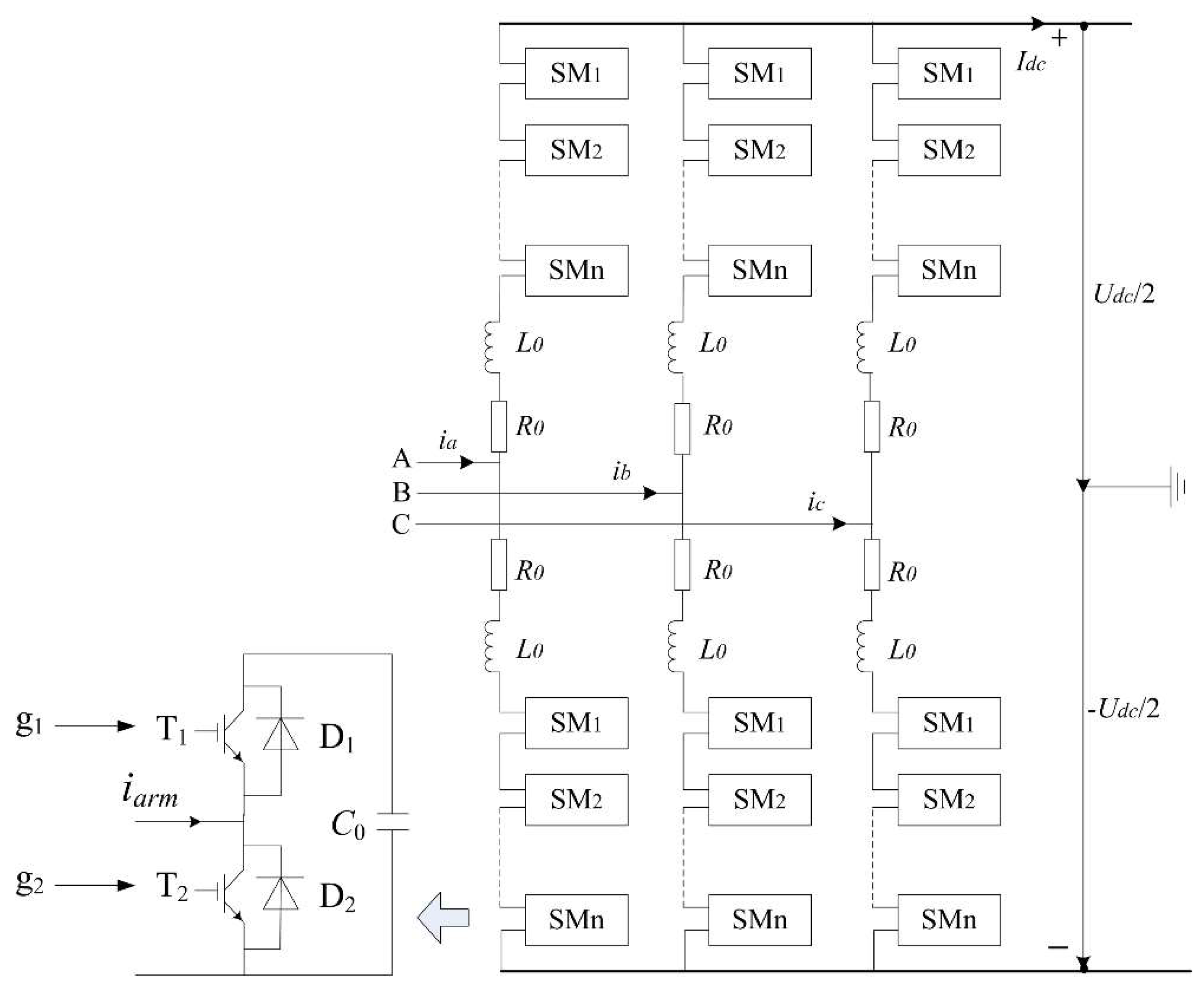
A three-phase MMC topology is illustrated in Figure 1 and each arm consists of n SMs, an arm inductor L0 and an equivalent loss resistance R0 in series. Each SM is composed of IGBT T1, T2, anti-paralleled diodes D1, D2 and a capacitor C0. The SM is set ON/OFF under the control of a switching function S which is defined as Equation (1)
where g1 and g2 are the gate signals for switches. When S is 1, the SM is “ON” and T1 is conducted and T2 is blocked. When S is 0, the SM is “OFF” and T1 is blocked and T2 is conducted. In normal operation, to maintain the required DC voltage, a Capacitor Voltage Balancing Method (CVBM) is applied in MMC-HVDC system [26,27]. The CVBM, SMs with higher voltages discharging (iarm < 0) in priority and SMs with lower voltages charging (iarm > 0) in priority, determines which SMs are ON/OFF, that is the value of S.
2.2. Fault Characteristics Analysis of SM
2.2.1. T1 Short-Circuit
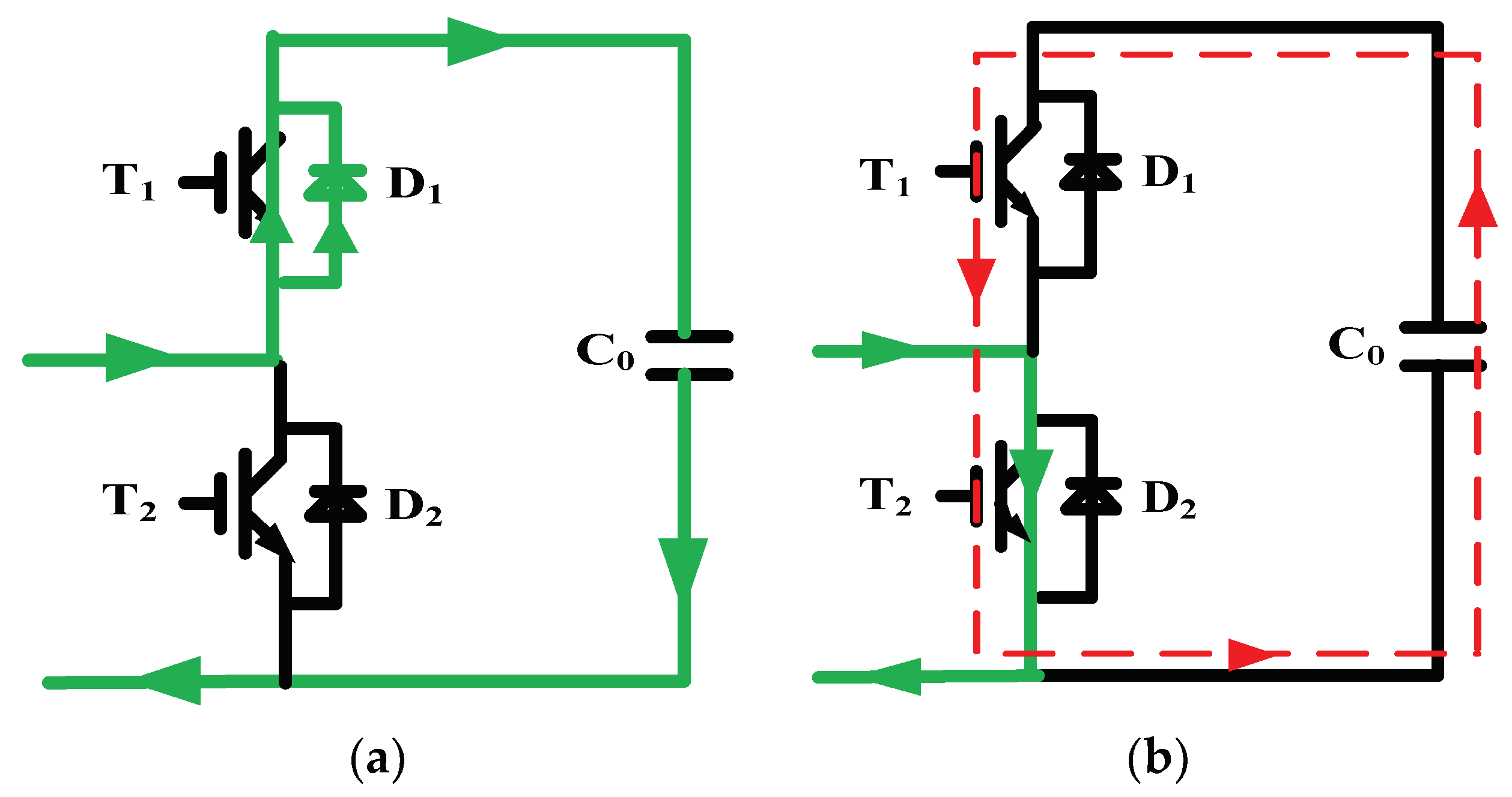
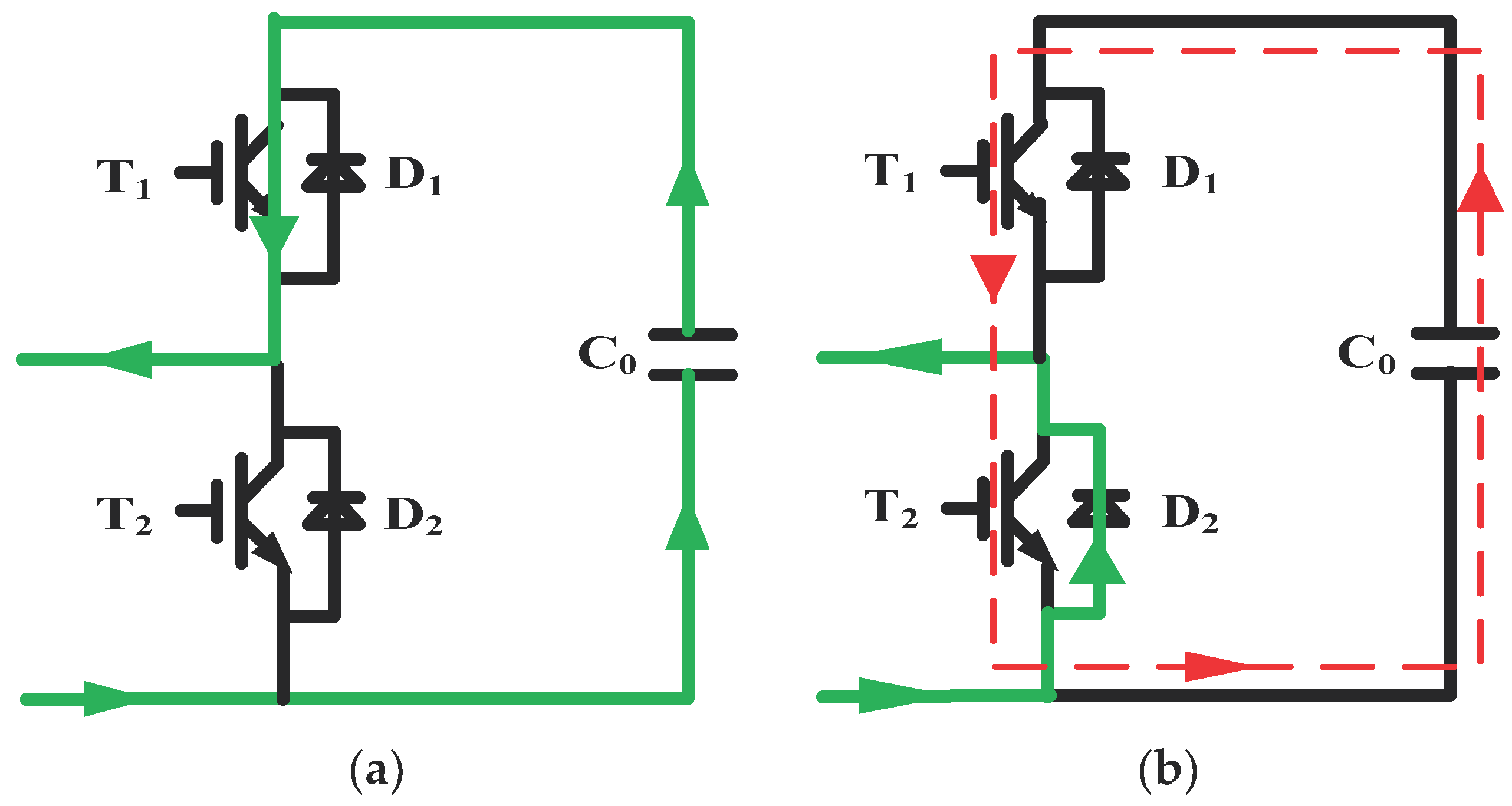
With iarm > 0 and S = 1, T1 short-circuit will have no impact on capacitor charging process. When S is 0 and T2 is conducted, T1 short-circuit will result in the capacitor’s short-circuit via T1 and T2 and the capacitor discharges rapidly. The current path is shown in Figure 2. Similarly, with iarm < 0 and S = 1, T1 short-circuit will have no influence on capacitor discharging process. Only when S is 0, T1 short-circuit will result in the capacitor short-circuit. The current path is shown in Figure 3.
2.2.2. T2 Short-Circuit
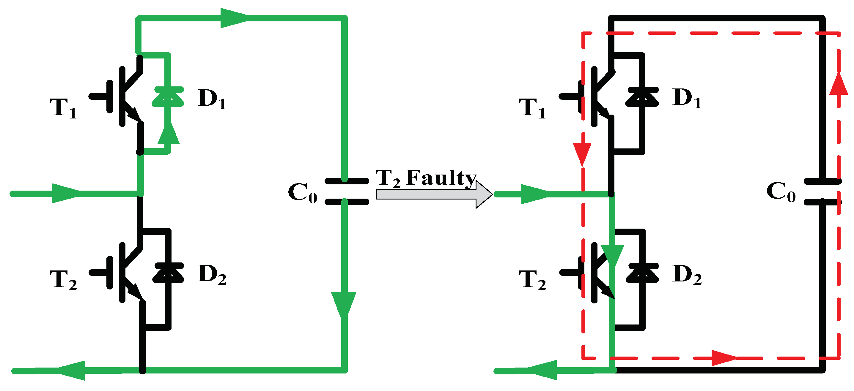
With iarm > 0 and S = 0, T2 short-circuit will have no impact on capacitor charging process. When S is 1, T2 short-circuit will cause the capacitor’s short-circuit via T1 and T2. As a result, the capacitor switches from normal charging state to fault discharging state. Similarly, with iarm < 0 and S = 1, T2 short-circuit will result in the capacitor switching from normal discharging state to fault discharging state. The current path is shown in Figure 4 and Figure 5.
Based on the analysis above, state of the capacitor under different IGBTs short-circuit faults can be obtained as shown in Table 2. It can be concluded that an IGBT short-circuit will result in the capacitor’s short-circuit once the other IGBT is “ON” in the same SM. Because of the small value of the time constant, the capacitor discharges rapidly. The capacitor voltage decreases and the capacitor current increases rapidly at the same time. The capacitor voltage and current saltation are the most apparent characteristics when short-circuit occurs, which can be applied to short-circuit detection method directly.
2.3. Capacitor Voltage Calculation
IGBT short-circuit will cause the capacitor to discharge via T1 and T2. The equivalent discharge circuit is illustrated as Figure 6. R1 and R2 are the equivalent on-resistance of T1 and T2, respectively and R equals R1 + R2. uc is the capacitor voltage and ic is the capacitor current.
The equivalent discharge circuit is a first-order RC circuit. Therefore, the circuit equations can be deduced as Equations (2) and (3)
With The initial state , so uc and its derivation can be deduced as Equations (4) and (5)
3. Proposed Fault Detection and Location Method for MMC
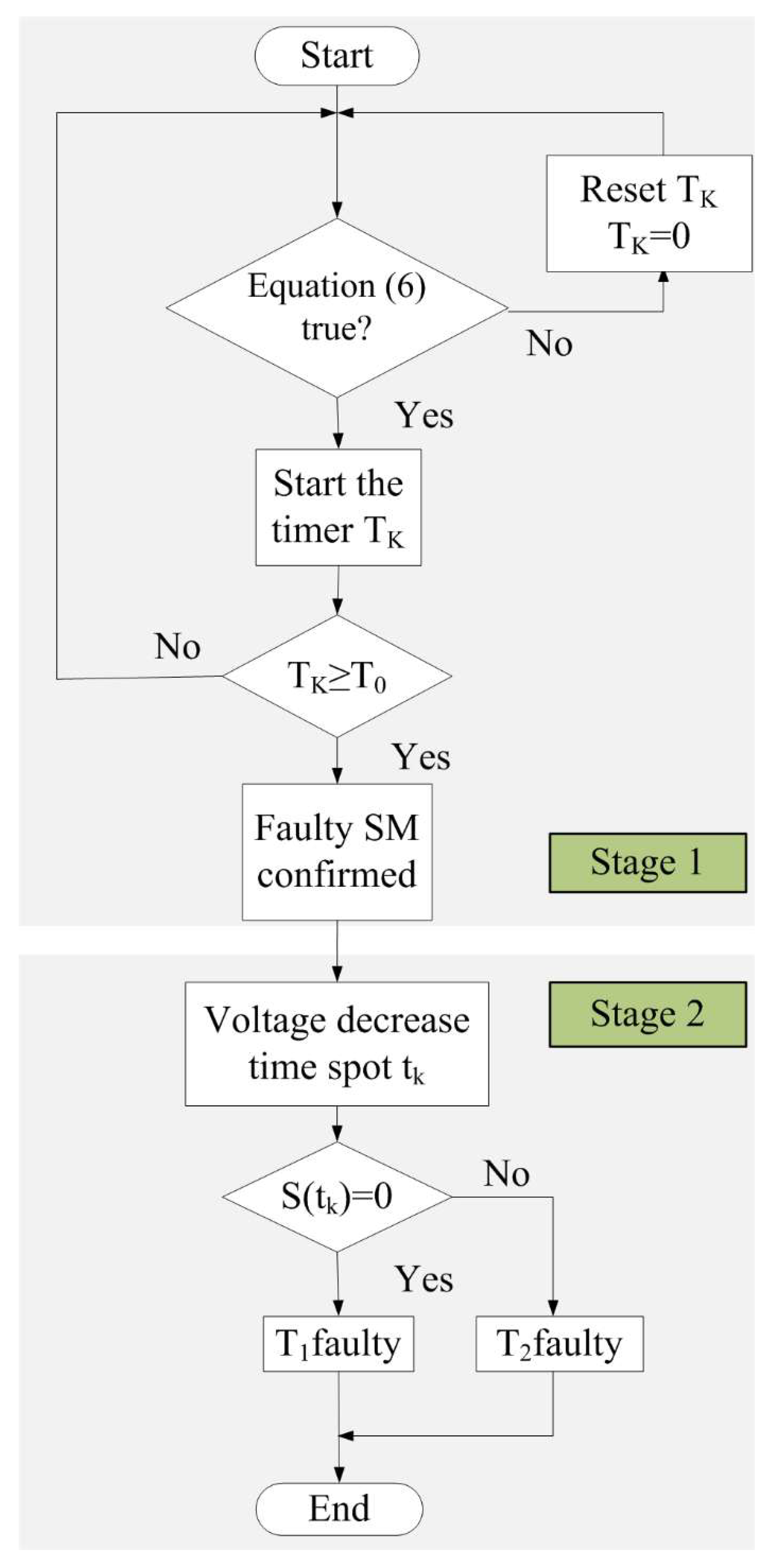
The short-circuit fault detection and location method for MMC proposed in this paper is divided into two stages. Stage 1: the fault SM detection. Stage 2: the fault IGBT location.
Stage 1: Faulty SM Detection
According to the fault characteristics analysis above, this paper proposes a novel Differential Comparison Low-Voltage Detection Method (DCLVDM) base on the capacitor voltage uc of the fault SM. The criteria of DCLVDM is formulated as Equation (6).
is the low-voltage part. α is the threshold value accordingly and is defined as Equation (7) where Kα is reliability coefficient and uce is the rated value of uc under steady state. is the differential comparison part. ε is the threshold value accordingly. duact and ducal are the actual value and calculation value of change rate of uc, respectively, and they are formulated as Equations (8) and (9). Ts is the sample period.
The criteria of DCLVDM consists of two parts: the low-voltage part and the differential comparison part. In the low-voltage part, a tentative conclusion that a short-circuit fault occurs can be reached if the capacitor voltage declines to the threshold value. However, IGBT short-circuit is not the only fault type which can cause capacitor voltage to decline, so differential comparison is introduced to confirm the fault. In differential comparison part, the calculation of duact is based on the short-circuit characteristics as Equation (5), hence, the error between duact and ducal under fault condition can be much smaller than that under steady state, which can be used to distinguish the fault. Only if Equation (6) is proved to be true and it lasts for a certain period T0, the IGBT short-circuit fault can be confirmed in a SM. The proposed DCLVDM requires no extra voltage measurement as the capacitor voltage is continuously measured for MMC control purpose.
Stage 2: Faulty IGBT Location Stage
As is indicated in Table 2, to locate the specific faulty IGBT, the value of Function S should be confirmed when the capacitor discharges. If there is S = 1(S = 0) at the time when the capacitor voltage decreases, then T2 (T1) is proved to be faulty. Hence the key to locate the faulty IGBT is to locate the time spot when the capacitor voltage begins to decrease, that is, the singularity of uc.
Continuous Wavelet Transform(CWT) is an effective time-frequency signal processing tool as it decomposes a signal in multiple scales or resolutions and retains both time and frequency domain information in the transform coefficients, which turns out to be useful in fault detection and location [28]. The CWT of a function f(t) with respect to a mother wavelet ψ(t) is defined as Equations (10) and (11)
Here, a and b are the scale and translation factors, respectively. ‘*’ indicates a complex conjugate. W(a,b) is the Wavelet Transform Coefficient (WTC) of f(t).
In time domain, the modulus maxima of the WTC represent the singularity of a signal and the degree of signal saltation can be characterized by the amplitude of the modulus maxima. For time-frequency analysis, a smoother continuous wavelet in time-domain is preferred as it brings better localization characteristics. In this paper, the second-order Gauss wavelet is chosen as the mother wavelet, which has excellent performance in the singularity detection [29].
To make the short-circuit fault detection and location method easier to understand, the flowchart of the method is displayed in Figure 7.
4. Case Studies
In this section, to evaluate the effectiveness of the proposed fault detection and location method, a two-terminal MMC-HVDC system is constructed in the professional software PSCAD/EMTDC. The MMC circuit parameters are given in the Appendix A. Two cases are conducted:
Case 1: short-circuit fault of T2 occurs in a SM at t = 0.02100 s.
Case 2: short-circuit fault of T1 occurs in a SM at t = 0.03500 s.
4.1. Fault Characteristics
Figure 8a,b show the MMC performance under faulty operation of case 1 and case 2, respectively. When the short-circuit fault occurs, the capacitor voltage deceases rapidly which results in the sharp increase of the capacitor current. As previously mentioned, the capacitor current flows within the SM and does not flow to the arms, hence, the fault will have no obvious influence on the arm current.
4.2. Fault Detection
Figure 9 shows the performance of the proposed DCLVDM. To ensure the reliability and sensitivity of the detection method, the values of Kα, ε and T0 are set as Kα = 0.8, ε = 0.7, T0 = 1 ms.
For Case 1, the short-circuit fault is detected 1.36 ms later after the fault occurs. The detection time is 1.26 ms for Case 2. The error between duact and ducal in steady state is much larger than that of faulty state, which is very useful in fault detection.
To prove the validity of the proposed DCLVDM, numerous simulations are carried out. The values of Kα, ε, T0 remain the same as mentioned above. The simulation performance is similar to Figure 9. Because of space constraints, the simulation performance is not displayed. The proposed DCLVDM combined with the proper value of related parameters can detect the short-circuit fault accurately. For reliability coefficient Kα, a larger value will improve the sensitivity of the low-voltage part to voltage decline, which can shorten the detection time. However, too large a value will reduce the reliability because potential disturbance or noise, etc. which may cause minor voltage decline, can be mistaken for short-circuit fault. For the threshold, ε, the value of ε should be set between the minimum of the differential comparison under steady state and the maximum under faulty state combined with a margin. In this paper, the range of ε is about 0.35–1.48 according to the simulations. Therefore, setting ε as 0.7 is sufficient and reasonable to detect the fault. As for T0, a larger value will improve the reliability of the fault detection process but lengthen the detection time. Because the IGBTs are of the same model in the same MMC converter and each SM has the same operation characteristics, the proposed DCLVDM and the parameter value setting are universally effective, which has been validated by numerous simulations. Actually, there is no a specification standard for the parameters setting with SM short-circuit, the parameters setting should take into consideration the sensitivity, speed, and reliability of the detection process comprehensively.
4.3. Fault Location
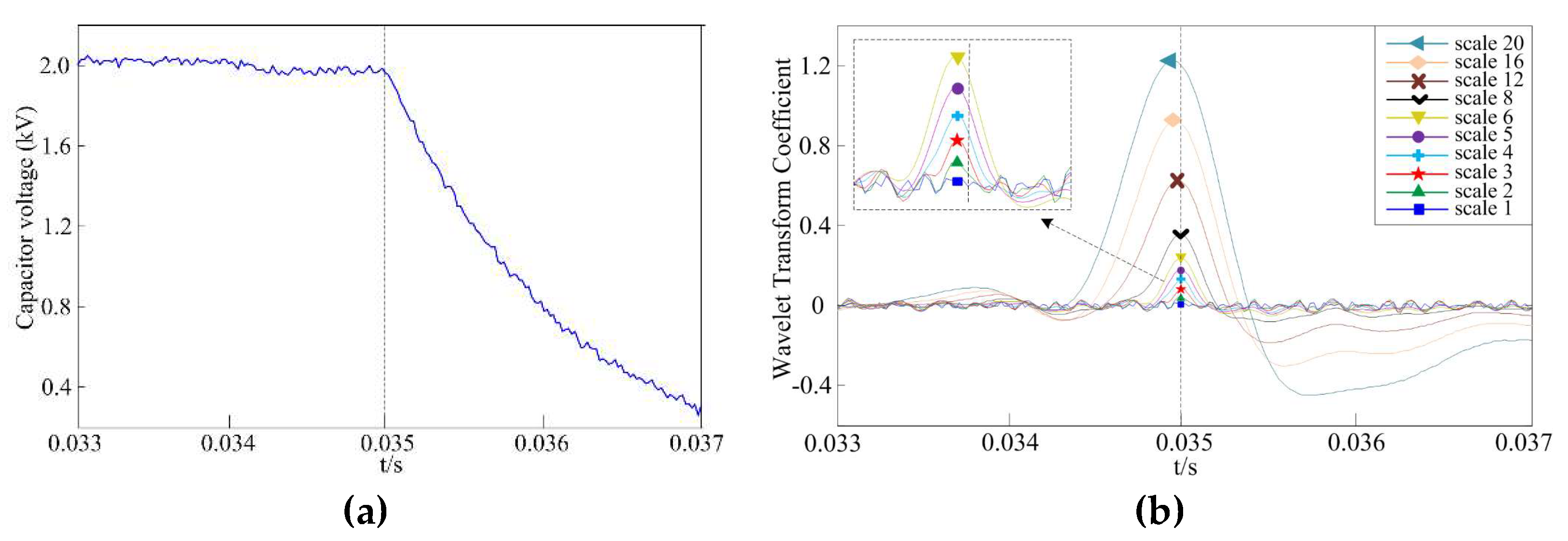
After the faulty SM is confirmed, the next step is to locate the faulty IGBT. As is mentioned above, the CWT of the capacitor voltage needs to be conducted. In this paper, the second-order Gauss wavelet is chosen as the mother wavelet as Equation (12). Magnitude values of the WTC are obtained for the corresponding input capacitor voltage for scale values of 1, 2, 3, 4, 5, 6, 8, 12, 16, and 20.
Figure 10 shows the performance of the Gauss wavelet under various scales on the capacitor voltage. It is noticed that the Gauss wavelet under scale 1 to 8 produces the WTC modulus maxima exactly at the voltage singularity. However, a location deviation is produced under scale 12, 16, and 20. So scale 1 to 8 is sufficient to detect the singularity under this simulation condition.
However, noise may occur in practical operation. To investigate the influence of noise on the accuracy of the estimated singularity point, 40-db white Gaussian noise is added to the voltage signal [30,31]. As the two cases have similar characteristics, only Case 2 is conducted as an example. The simulation result is shown in Figure 11.
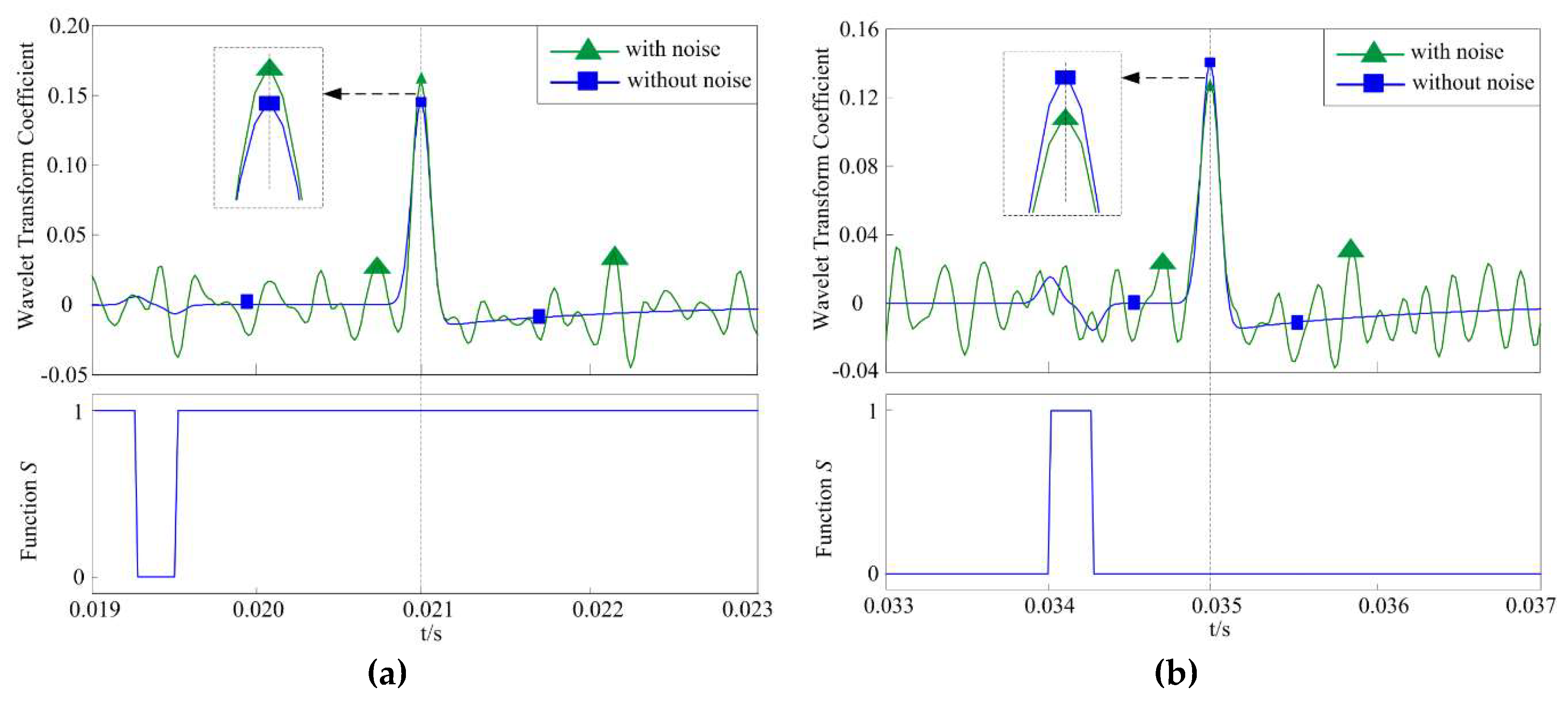
In Figure 11, firstly, a location deviation is still produced under scale 12, 16, and 20. Secondly, the fault singularity is hard to locate under scale 1 and 2 as the noise produces many more singularities in the process. Lastly, scale 3 to 8 may be chosen to locate the voltage singularity because the amplitude of the modulus maxima produced by the fault is much higher than that produced by the noise. Therefore, to locate the voltage singularity, the value of the scale cannot be too high or too low. In this paper, scale 4 is chosen to conduct the fault location as is shown in Figure 12.
Figure 12 shows the detailed Wavelet Transform Coefficient (WTC) of SM voltages under scale 4 with or without noise, as well as their Function S. The singularity of the capacitor voltage caused by the fault is accurately located by the WTC modulus maxima. In Figure 12a, the singularity is located at t = 0.02100 s, meanwhile, the value of S is 1, So T2 is proved to be faulty. Similarly, T1 can be proved to be faulty according to Figure 12b at t = 0.03500 s. The proposed faulty IGBT location method based on CWT can accurately locate the singularity of the voltage capacitor caused by the fault, thus locating the faulty IGBT efficiently and precisely.
4.4. Comparison Analysis
As introduced in [22,23,24,25], most conventional IGBT fault detection and protection methods are hardware circuit-based and very few are algorithm-based. Hardware-based detection methods configure a detailed detection circuit for every single IGBT. In the detection circuit, gate voltage, collector-emitter voltage, collector current, etc. are been measured to detect the abnormal operation of IGBT. Therefore, hardware-based detection methods can detect the fault rapidly. However, MMC is composed of a series of SMs and each SM contains two IGBTs, thus, For an N+1 level half-bridge MMC system shown in Figure 1, at least 12N IGBTs are configured. Therefore, if the hardware detection method is adopted, for a 501-level MMC, 6000 detection circuits have to be configured besides more sensors. It absolutely adds complexity and huge cost to the MMC system. The proposed fault detection and location method in this paper is algorithm-based. The method detects the fault only by the capacitor voltage and the switch function, requiring no detection circuit or additional sensors as the capacitor voltage and switch function are originally measured for MMC control purpose. Therefore, hardware-based detection method and the algorithm-based method proposed in this paper have merits and demerits respectively, especially for IGBT of MMC, but they both provide valuable reference for MMC protection system construction in the future work.
5. Conclusions
In this paper, a novel fault detection and location method is proposed for IGBT short-circuit fault in MMC based on the SM capacitor voltage. The fault detection is carried out based on the proposed Differential Comparison Low-Voltage Detection Method (DCLVDM). No additional sensors are required, and a simple arithmetic operation is sufficient to detect the faulty SM. The fault location is fulfilled by the Continuous Wavelet Transform (CWT) based on the capacitor voltage of the faulty SM. The proposed method not only detects the faulty SM rapidly, but it can also locate the specific faulty IGBT precisely. Simulation studies conducted in PSCAD/EMTDC prove that the proposed fault detection and location method in this paper is effective. In respect of practical application, this method requires accurate voltage measurement and fast sampling frequency, both of which bring more challenges to the sensors and the calculation equipment. Both reliability and rapidity must be taken into consideration when setting the corresponding threshold values of DCLVDM. In the future, the authors will conduct deep research on the influence exerted by different disturbances and other fault location methods besides wavelet and aim to make the fault detection and location of IGBT short-circuit failure in MMC more universal, reliable and feasible.
Author Contributions
B.J. defined the problem, proposed the fault detection method and conducted the simulation. Y.G. developed the fault location method. Y.L. gathered the necessary data. B.J. and Y.G. contributed in the paper writing. B.J. and Y.L. handled the paper revisions.
Acknowledgments
This research was funded by “the Fundamental Research Funds for the Central Universities 2017XS015”.
Conflicts of Interest
The authors declare no conflict of interest.
Appendix A

Table A1.
Parameters of the simulated MMC system.
| Quantity | Value |
|---|---|
| DC nominal voltage (Udc) | ±20 kV |
| Number of SMs per arm (N) | 20 |
| Power transmission (P) | 20 MW |
| Arm inductor (L0) | 15 mH |
| SM capacitance (C0) | 6 mF |
| AC line voltage (Vac) | 10 kV |
| Loss resistance (R0) | 0.1 Ω |
| SM capacitor voltage | 2 kV |
| equivalent on-resistance (R1, R2) | 0.01 Ω |
References
- Debnath, S.; Qin, J.; Bahrani, B.; Saeedifard, M.; Barbosa, P. Operation, Control, and Applications of the Modular Multilevel Converter: A Review. IEEE Trans. Power Electron. 2015, 30, 37–53. [Google Scholar] [CrossRef]
- Perez, M.A.; Bernet, S.; Rodriguez, J.; Kouro, S.; Lizana, R. Circuit Topologies, Modeling, Control Schemes, and Applications of Modular Multilevel Converters. IEEE Trans. Power Electron. 2015, 30, 4–17. [Google Scholar] [CrossRef]
- Nami, A.; Liang, J.; Dijkhuizen, F.; Demetriades, G.D. Modular Multilevel Converters for HVDC Applications: Review on Converter Cells and Functionalities. IEEE Trans. Power Electron. 2015, 30, 18–36. [Google Scholar] [CrossRef]
- Harnefors, L.; Antonopoulos, A.; Norrga, S.; Angquist, L.; Nee, H.P. Dynamic Analysis of Modular Multilevel Converters. IEEE Trans. Ind. Electron. 2013, 60, 2526–2537. [Google Scholar] [CrossRef]
- Gebreel, A.A.; Xu, L. Power quality and total harmonic distortion response for MMC with increasing arm inductance based on closed loop–needless PID controller. Electr. Power Syst. Res. 2016, 133, 281–291. [Google Scholar] [CrossRef]
- Rohner, S.; Bernet, S.; Hiller, M.; Sommer, R. Modulation, Losses, and Semiconductor Requirements of Modular Multilevel Converters. IEEE Trans. Ind. Electron. 2010, 57, 2633–2642. [Google Scholar] [CrossRef]
- Wu, J.; Wang, Z.X.; Xu, L.; Wang, G.Q. Key technologies of VSC–HVDC and its application on offshore wind farm in China. Renew. Sustain. Energy Rev. 2014, 36, 247–255. [Google Scholar] [CrossRef]
- Jiang, B.; Wang, Z. The key technologies of VSC–MTDC and its application in China. Renew. Sustain. Energy Rev. 2016, 62, 297–304. [Google Scholar]
- Shao, S.; Watson, A.J.; Clare, J.C.; Wheeler, P.W. Robustness Analysis and Experimental Validation of a Fault Detection and Isolation Method for the Modular Multilevel Converter. IEEE Trans. Power Electron. 2016, 31, 3794–3805. [Google Scholar] [CrossRef] [Green Version]
- Sujil, A.; Choudhary, S.; Verma, J.; Kumar, R. Agent based intelligent fault detection, isolation and restoration in smart power system. In Proceedings of the 2016 IEEE Students’ Conference on Electrical, Electronics and Computer Science (SCEECS), Bhopal, India, 5–6 March 2016; pp. 1–6. [Google Scholar]
- Hwang, I.; Kim, S.; Kim, Y.; Seah, C.E. A Survey of Fault Detection, Isolation, and Reconfiguration Methods. IEEE Trans. Control Syst. Technol. 2010, 18, 636–653. [Google Scholar] [CrossRef]
- Lu, B.; Sharma, S.K. A Literature Review of IGBT Fault Diagnostic and Protection Methods for Power Inverters. IEEE Trans. Ind. Appl. 2009, 45, 1770–1777. [Google Scholar]
- Yang, S.; Bryant, A.; Mawby, P.; Xiang, D.; Ran, L.; Tavner, P. An Industry–Based Survey of Reliability in Power Electronic Converters. IEEE Trans. Ind. Appl. 2011, 47, 1441–1451. [Google Scholar] [CrossRef]
- Salimian, H.; Iman–Eini, H.; Farhangi, S. Open–circuit fault detection and location in Modular Multilevel Converter. In Proceedings of the 6th Power Electronics, Drive Systems & Technologies Conference (PEDSTC2015), Tehran, Iran, 3–4 February 2015; pp. 383–388. [Google Scholar]
- Haghnazari, S.; Khodabandeh, M.; Zolghadri, M.R. Fast fault detection method for modular multilevel converter semiconductor power switches. IET Power Electron. 2016, 9, 165–174. [Google Scholar] [CrossRef]
- Shao, S.; Wheeler, P.W.; Clare, J.C.; Watson, A.J. Fault Detection for Modular Multilevel Converters Based on Sliding Mode Observer. IEEE Trans. Power Electron. 2013, 28, 4867–4872. [Google Scholar] [CrossRef] [Green Version]
- Li, B.; Shi, S.; Wang, B.; Wang, G.; Wang, W.; Xu, D. Fault Diagnosis and Tolerant Control of Single IGBT Open–Circuit Failure in Modular Multilevel Converters. IEEE Trans. Power Electron. 2016, 31, 3165–3176. [Google Scholar] [CrossRef]
- Deng, F.; Chen, Z.; Khan, M.R.; Zhu, R. Fault Detection and Location Method for Modular Multilevel Converters. IEEE Trans. Power Electron. 2015, 30, 2721–2732. [Google Scholar] [CrossRef]
- Chokhawala, R.S.; Catt, J.; Kiraly, L. A discussion on IGBT short-circuit behavior and fault protection schemes. IEEE Trans. Ind. Appl. 1995, 31, 256–263. [Google Scholar] [CrossRef] [Green Version]
- Barnes, M.J.; Blackmore, E.; Wait, G.D.; Lemire-Elmore, J.; Rablah, B.; Leyh, G.; Nguyen, M.N.; Pappas, C. Analysis of High–Power IGBT Short Circuit Failures. IEEE Trans. Plasma Sci. 2005, 33, 1252–1261. [Google Scholar] [CrossRef]
- Yazdani, A.; Sepahvand, H.; Crow, M.L.; Ferdowsi, M. Fault Detection and Mitigation in Multilevel Converter STATCOMs. IEEE Trans. Ind. Electron. 2011, 58, 1307–1315. [Google Scholar] [CrossRef]
- Brando, G.; Dannier, A.; del Pizzo, A.; Rizzo, R. Quick identification technique of fault conditions in cascaded H–Bridge multilevel converters. In Proceedings of the 2007 International Aegean Conference on Electrical Machines and Power Electronics, Bodrum, Turkey, 10–12 September 2007; pp. 491–497. [Google Scholar]
- Shahbazi, M.; Zolghadri, M.R.; Poure, P.; Saadate, S. Fast short circuit power switch fault detection in cascaded H–bridge multilevel converter. In Proceedings of the 2013 IEEE Power & Energy Society General Meeting, Vancouver, BC, Canada, 21–25 July 2013; pp. 1–5. [Google Scholar]
- Lee, J.B.; Hyun, D.S. Gate Voltage Pattern Analyze for Short-circuit Protection in IGBT Inverters. In Proceedings of the 2007 IEEE Power Electronics Specialists Conference, Orlando, FL, USA, 17–21 June 2007; pp. 1913–1917. [Google Scholar]
- Lihua, C.; Peng, F.Z.; Cao, D. A smart gate drive with self–diagnosis for power MOSFETs and IGBTs. In Proceedings of the 2008 Twenty–Third Annual IEEE Applied Power Electronics Conference and Exposition, Austin, TX, USA, 24–28 February 2008; pp. 1602–1607. [Google Scholar]
- Yinglin, X.; Zheng, X. On the Bipolar MMC–HVDC Topology Suitable for Bulk Power Overhead Line Transmission: Configuration, Control, and DC Fault Analysis. IEEE Trans. Power Deliv. 2014, 29, 2420–2429. [Google Scholar]
- Wang, S.S.; Zhou, X.X.; Tang, G.F.; He, Z.; Teng, L.; Bao, H.L. Analysis of submodule overcurrent caused by dc pole–to–pole fault in modular multilevel converter HVDC system. Proc. CSEE 2011, 31, 1–7. (In Chinese) [Google Scholar]
- Silva, M.D.; Coury, D.V.; Oleskovicz, M.; Segatto, E.C. Combined solution for fault location in three–terminal lines based on wavelet transforms. IET Gener. Trans. Dis. 2010, 4, 94–103. [Google Scholar] [CrossRef]
- Lin, S.; He, Z.Y.; Li, X.P.; Qian, Q.Q. Travelling wave time–frequency characteristic–based fault location method for transmission lines. IET Gener. Trans. Dis. 2012, 6, 764–772. [Google Scholar] [CrossRef]
- Azizi, S.; Sanaye–Pasand, M.; Abedini, M.; Hasani, A. A Traveling–Wave–Based Methodology for Wide–Area Fault Location in Multi–terminal DC Systems. IEEE Trans. Power Deliv. 2014, 29, 2552–2560. [Google Scholar] [CrossRef]
- Liu, X.; Osman, A.H.; Malik, O.P. Hybrid Traveling Wave/Boundary Protection for Monopolar HVDC Line. IEEE Trans. Power Deliv. 2009, 24, 569–578. [Google Scholar] [CrossRef]
Figure 1.
Three-phase MMC topology.

Figure 2.
Current path when T1 is short-circuit with iarm > 0. (a) S = 1. (b) S = 0.

Figure 3.
Current path when T1 is short-circuit with iarm < 0: (a) S = 1; (b) S = 0.

Figure 4.
Current path when T2 is short-circuit with iarm > 0 and S = 1.

Figure 5.
Current path when T2 is short-circuit with iarm < 0 and S = 1.
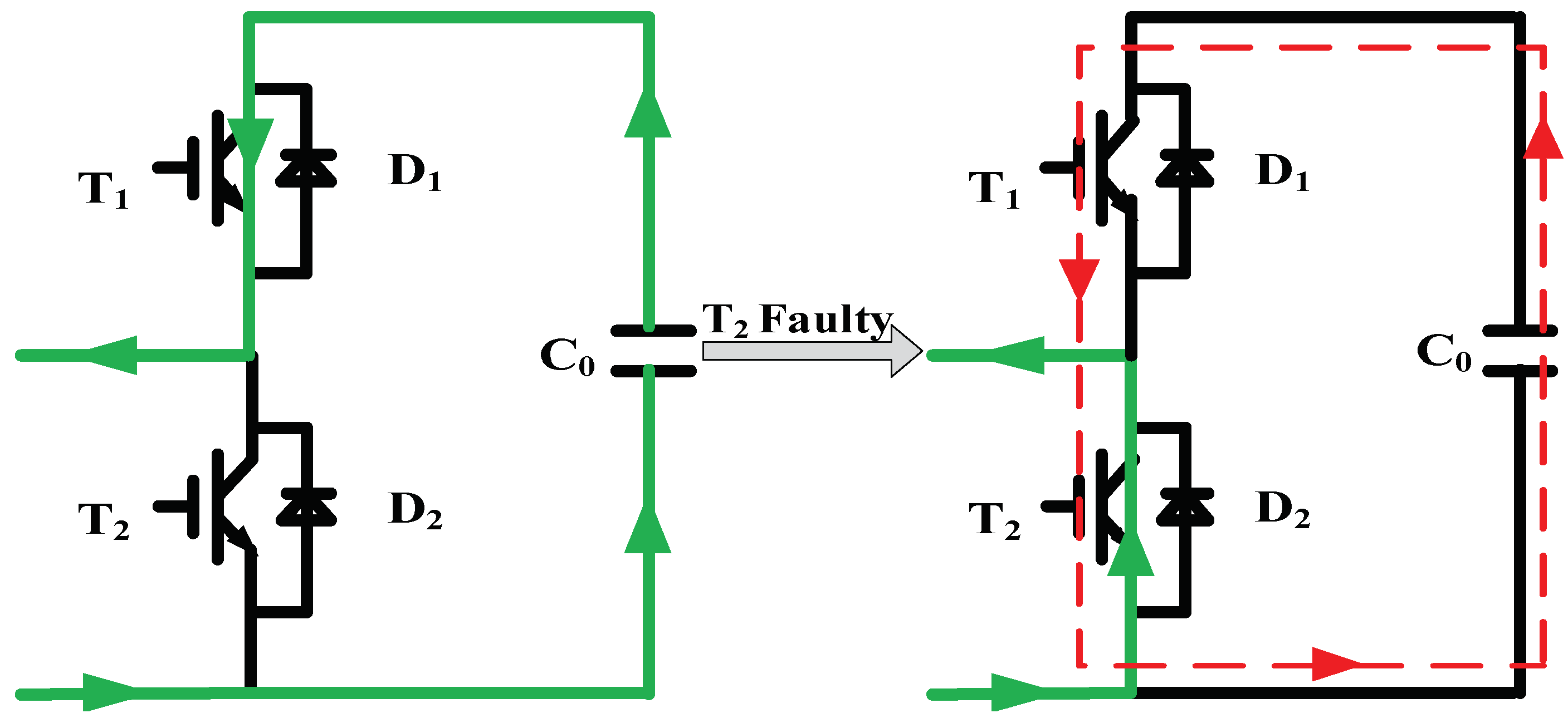
Figure 6.
Equivalent discharge circuit for the capacitors.
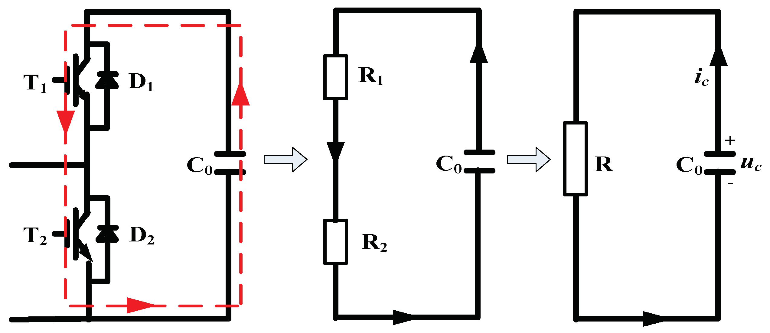
Figure 7.
Flowchart of the short-circuit fault detection and location method.

Figure 8.
Performance of MMC under faulty operation: (a) Case 1; (b) Case 2.
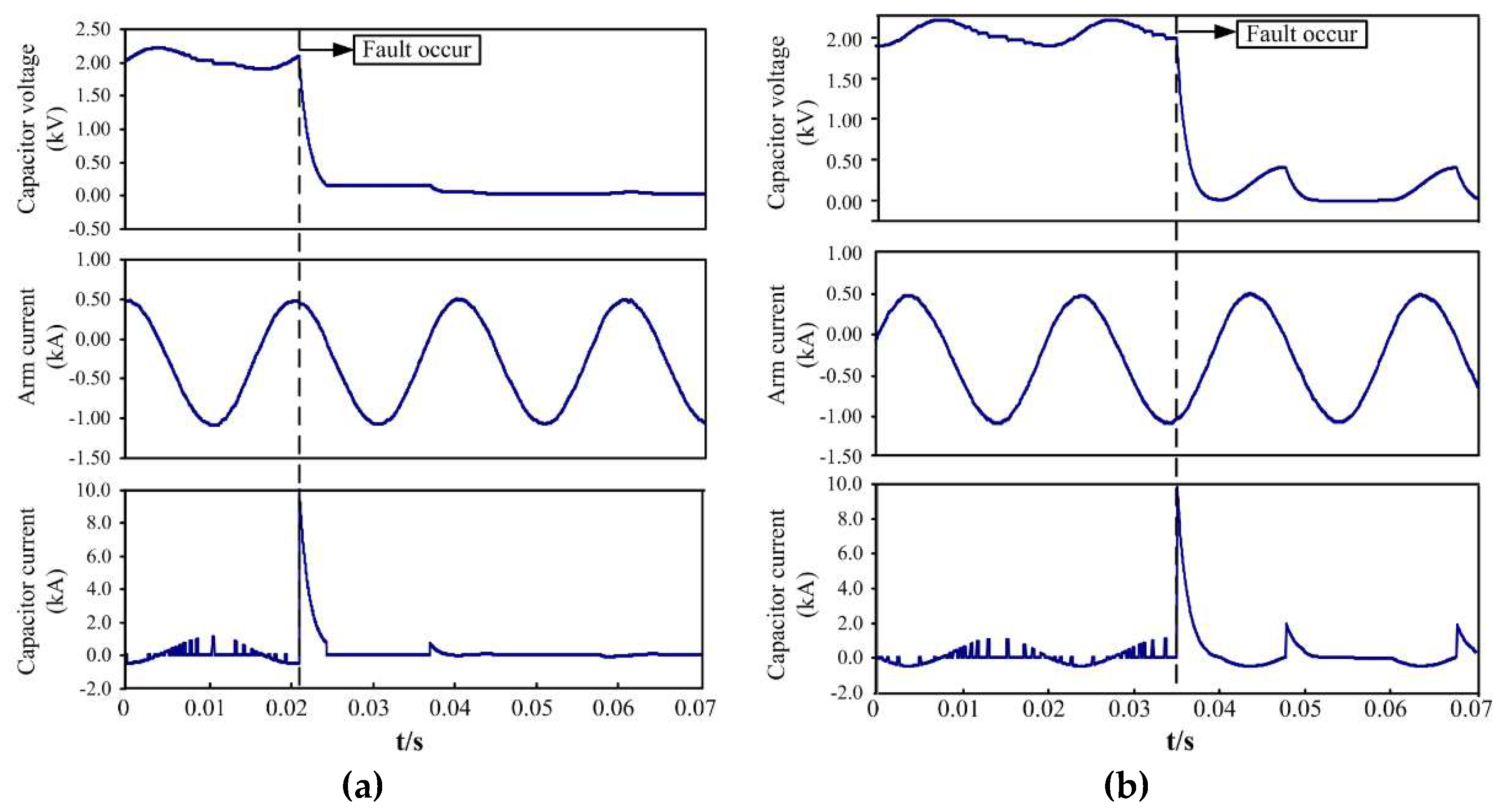
Figure 9.
Performance of the proposed DCLVDM under faulty condition: (a) Case 1; (b) Case 2.
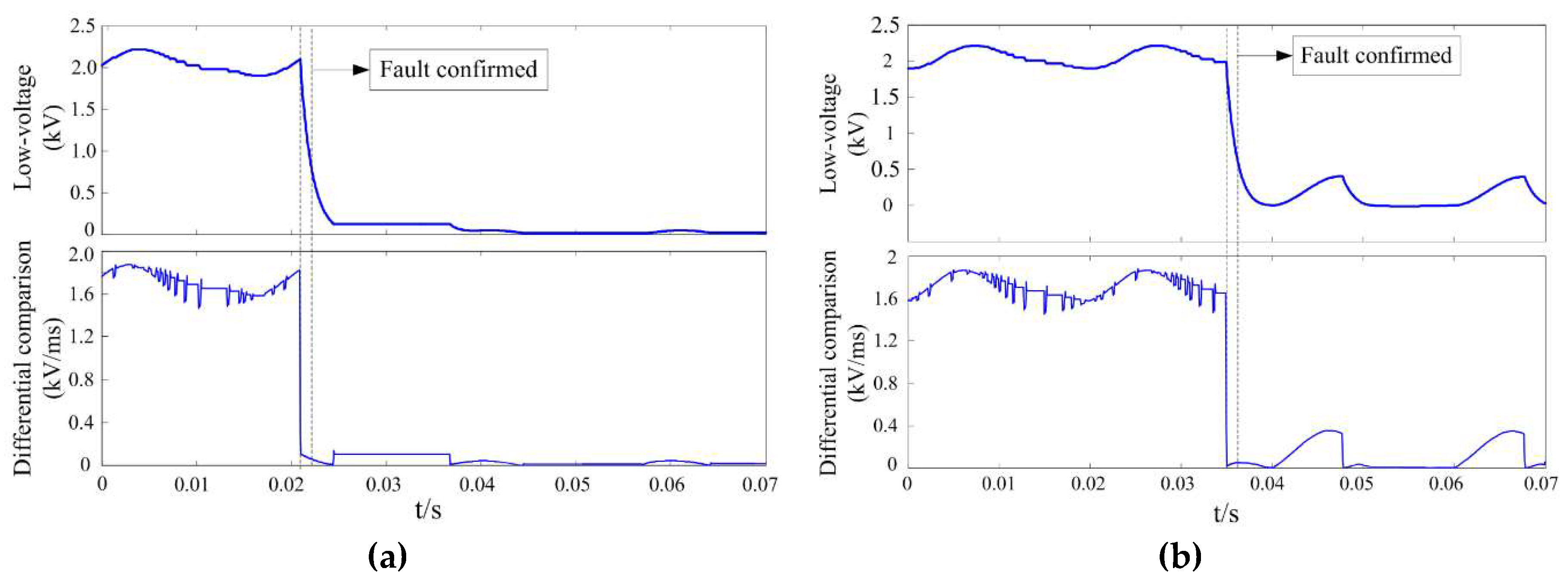
Figure 10.
Wavelet Transform Coefficient under various scales: (a) Case 1; (b) Case 2.
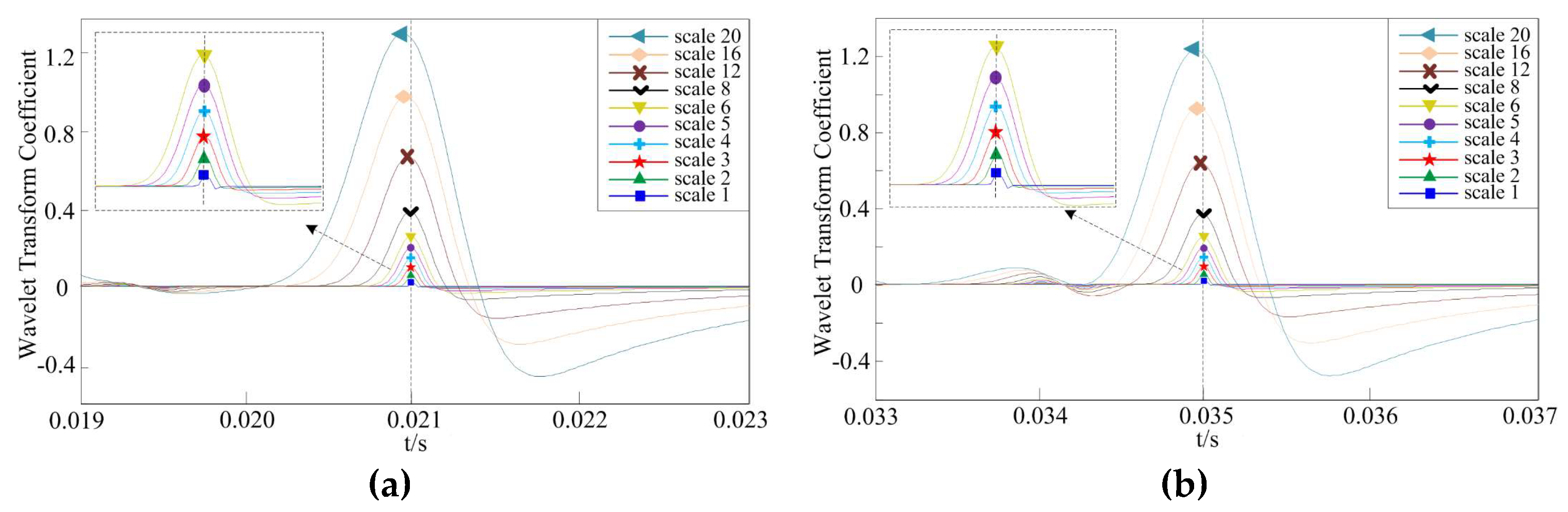
Figure 11.
Fault location result with 40-db white Gaussian noise for Case 2: (a) Contaminated capacitor voltage; (b) Wavelet Transform Coefficients under various scales.
Figure 11.
Fault location result with 40-db white Gaussian noise for Case 2: (a) Contaminated capacitor voltage; (b) Wavelet Transform Coefficients under various scales.

Figure 12.
Faulty IGBT location under scale 4: (a) Case 1; (b) Case 2.

Table 1.
Fault detection methods.
| Reference | Requires | Complexity | Detection Time |
|---|---|---|---|
| [21] | output voltage and gate signal | simple calculation | about 1 cycle |
| [22,23] | phase voltage | complex model and additional sensors | numbers of sampling intervals |
| [24,25] | gate voltage or current | additional sensors and circuits | tens of microseconds |
Table 2.
State of the capacitor under different IGBTs short-circuit faults.
| Fault IGBT | SM State | S | iarm | Capacitor State |
|---|---|---|---|---|
| T1 | ON | 1 | >0 | Normal |
| <0 | Normal | |||
| OFF | 0 | >0 | Short-circuit | |
| <0 | Short-circuit | |||
| T2 | ON | 1 | >0 | Short-circuit |
| <0 | Short-circuit | |||
| OFF | 0 | >0 | Normal | |
| <0 | Normal |
© 2018 by the authors. Licensee MDPI, Basel, Switzerland. This article is an open access article distributed under the terms and conditions of the Creative Commons Attribution (CC BY) license (http://creativecommons.org/licenses/by/4.0/).
Share and Cite
MDPI and ACS Style
Jiang, B.; Gong, Y.; Li, Y. Fault Detection and Location of IGBT Short-Circuit Failure in Modular Multilevel Converters. Energies 2018, 11, 1492. https://doi.org/10.3390/en11061492
AMA Style
Jiang B, Gong Y, Li Y. Fault Detection and Location of IGBT Short-Circuit Failure in Modular Multilevel Converters. Energies. 2018; 11(6):1492. https://doi.org/10.3390/en11061492
Chicago/Turabian StyleJiang, Bin, Yanfeng Gong, and Yan Li. 2018. "Fault Detection and Location of IGBT Short-Circuit Failure in Modular Multilevel Converters" Energies 11, no. 6: 1492. https://doi.org/10.3390/en11061492
Note that from the first issue of 2016, this journal uses article numbers instead of page numbers. See further details here.