Article

Dual-Side Independent Switched Capacitor Control for Wireless Power Transfer with Coplanar Coils

School of Electric Power Engineering, South China University of Technology, Guangzhou 510641, China
*
Author to whom correspondence should be addressed.
Energies 2018, 11(6), 1472; https://doi.org/10.3390/en11061472
Submission received: 24 April 2018 / Revised: 26 May 2018 / Accepted: 29 May 2018 / Published: 6 June 2018

Abstract

:
The transfer coils of traditional Magnetic Coupling Resonant Wireless Power Transfer (MCR-WPT) systems are generally arranged coaxially. Coplanar coils can be an alternative scheme that can save more space in some applications, such as mobile phone wireless charging. However, the inductances of coplanar coils are sensitive to foreign objects, which leads to a reduction in transfer efficiency and output power. A MCR-WPT system with coplanar coils and its control strategy are proposed in this paper. First, the characteristic of the mutual inductance and the magnetic field distribution between the coplanar coils are analyzed. A formula to calculate mutual inductance between the coplanar coils is proposed in this part. Secondly, the effect of inductance offset and frequency detuning on transfer efficiency and output power are analyzed. Then, the control strategy to eliminate frequency detuning is proposed. The proposed method implements switched capacitor to take place of constant compensation capacitor. The equivalent capacitance of switched capacitor is adjusted when the frequency detuning occurred. Thus, the inherent frequency of the resonant tank tracks the source frequency all the time. Since the switched capacitor of each side is controlled based on the quantity of their own, the control process is independent and does not require wireless communication. The complexity and the cost of the system are reduced. At the end of the article, the veracity of mutual inductance formula and the effectiveness of the proposed control strategy are verified by experiments. The experimental coils are placed in in an environment full of interference. The inductances of the coils are reduced from 224 μH to about 214 μH. The transfer efficiency and output power of MCR-WPT system with closed-loop control are higher than the one without control. At a distance of 5 cm from edge to edge, the transfer efficiency is 76.37% under the proposed control and 72.21% under no control. The output power is 285.66 W under the proposed control and 271.37 W under no control.

1. Introduction

Magnetic Coupling Resonance Wireless Power Transfer technology (MCR-WPT) is one of the most popular research topics at present. Since the introduction of this technology in 2007 [1], it has been widely applied in medicine, domesticity and industry. MCR-WPT technology brings a lot of convenience for people’s lives.
In the previous studies and applications, the coils used in the MCR-WPT system are almost all arranged coaxially [2,3,4]. However, the secondary coil may not align accurately with the primary coil in some applications, such as mobile phones, smartwatches, floor lamps, etc. In some cases, the primary coil and secondary coil may even be put in the same plane. Thus, the mutual inductance and magnetic field distribution are different from the coaxial ones. There are some works that have analyzed the mutual inductance of coils with lateral misalignment [5] or with angular azimuth misalignment [6]. However, there is no research on the MCR-WPT system with coplanar coils. This kind of coils arrangement has been neglected before.
Inductances of coils are very sensitive to external interferences. For instance, ferrite cores are used frequently in the design of coils to improve the mutual inductance. However, ferrite cores can change the distribution of the magnetic field [7]. Thus, the inductances of coils will vary significantly with misalignment. Metal objects outside coils can also cause the instability of inductances. Meanwhile, the capacitances of compensation capacitors in the MCR-WPT system may be affected by temperature, frequency, bias voltage, etc. Therefore, the inherent frequency of the resonant tanks consisting of an inductor and compensation capacitor is changed accordingly and deviates from the source frequency, which is called frequency detuning. Transfer efficiency decreases rapidly and output power deviates from the rated value when frequency detuning occurs. Therefore, it is important to eliminate frequency detuning by using a certain control strategy. Many methods to deal with this problem are reported in previous works, including frequency tracking [7,8,9], impedance matching (IM) [10,11] and compensation capacitor tuning [12,13,14]. In [8], a phase-locked-loop (PLL) controller is applied to the primary side. The source frequency is adjusted to track the inherent frequency of the primary resonant tank. In [7,9], the frequency source is adjusted to track the zero phase difference between the source voltage and primary current or between the source voltage and secondary current. By applying frequency tracking, the output power is controlled robustly and the transfer efficiency becomes more stable. However, the source frequency varies significantly by applying frequency tracking control strategy. The usable frequency range is bounded by design standards such as those of the industrial, scientific, and medical (ISM) band, non-contact electric vehicle wireless charging standard SAE TIR J2954 [15], etc. Meanwhile, the filter design becomes more difficult. IM control is a method that adds an adaptive impedance matching network between the inverters and the primary resonant network or the rectifier and secondary resonant network. The scheme of adaptive IM network consists of a capacitor-switch matrix [10,11]. The method tracks the maximal S-parameters. Thus, the output power remains at the maximum, however, the system efficiency is lower than 50%. Compensation capacitor tuning changes the adjustable resonant capacitor to adjust the inherent frequency of the resonant tank directly. In [12,13], the adjustable capacitor is only implemented on the primary side to keep the inherent frequency of the primary side equal to the source frequency. However, this method has no effect on the secondary side. In [14], adjustable capacitors are applied to both sides. However, this control strategy should use wireless communication, which increases the complexity of control and cost.
In this paper, a novel dual-side independent switched capacitor control strategy for MCR-WPT systems with coplanar coils is proposed. By applying the control strategy, the frequency detuning of dual-side resonant tanks can be dealt with and the transfer efficiency increases compared to the system without control. The coils proposed in this paper are arranged coplanarly. In some cases, the coplanar coils can save more space than coaxial ones. This paper is organized as follows: Section 2 analyzes the mutual inductance and magnetic field distribution between coplanar coils, in which the formula of mutual inductance is derived. Section 3 investigates the effect of frequency detuning on transfer efficiency and output power. The dual-side independent switched capacitor control strategy and specific control scheme are also proposed in this section. Section 4 presents the measurement results of the experiment. Finally, Section 5 draws the conclusions.

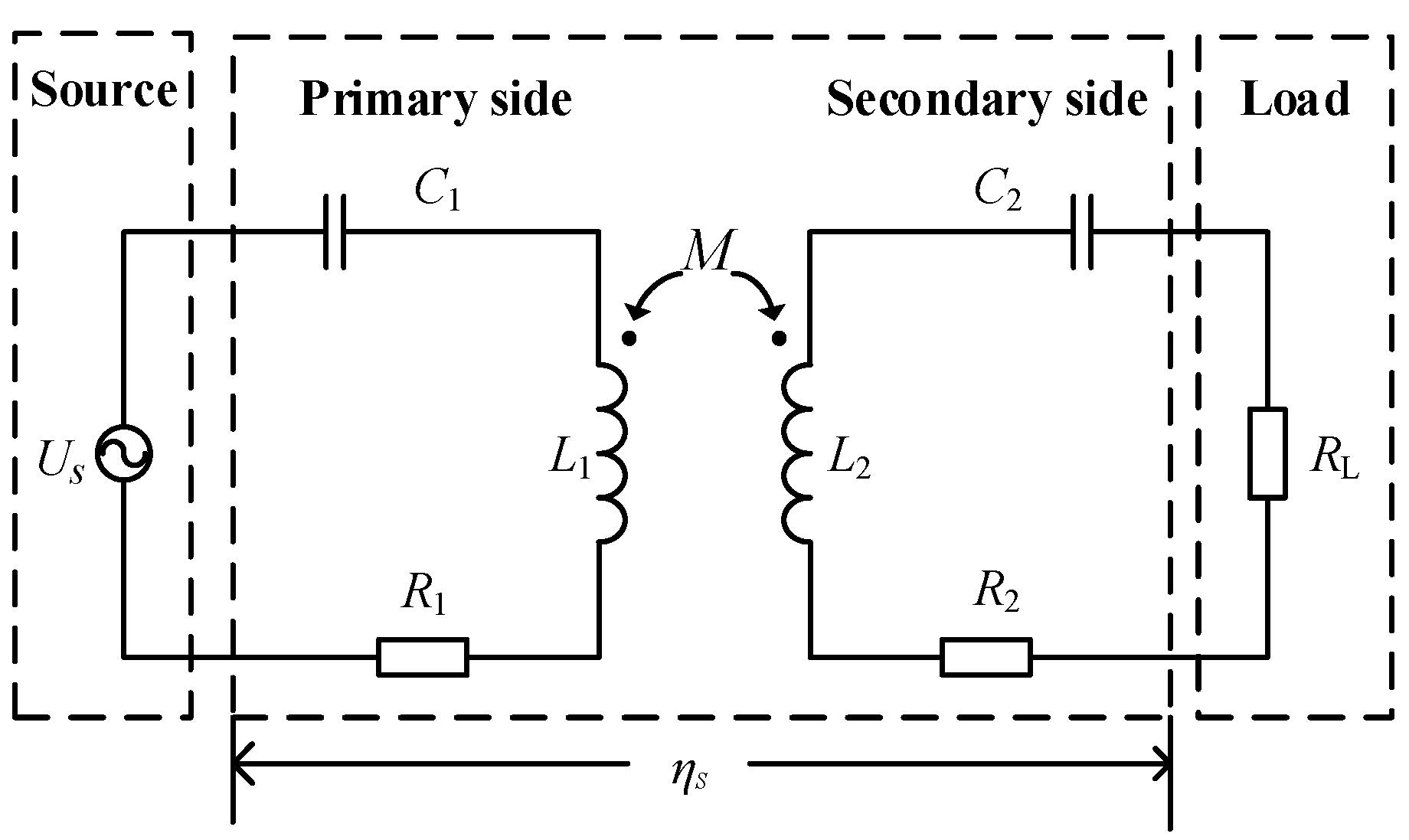
2. Analysis of Coplanar Coils

2.1. Calculation of Mutual Inductance

The equivalent circuit of a MRC-WPT system is depicted in Figure 1, where L1,2, C1,2, and R1,2 are the inductors of coils, compensation capacitors, and Equivalent Series Resistance (ESR) respectively. The losses of inverter, rectifier, inductors, and capacitors are all included in the ESR for the sake of simplicity. M is the mutual inductance between the primary coil and the secondary coil. ηS is the efficiency from the primary side to the secondary side, which is called transfer efficiency in the following sections.
When the MCR-WPT system transfers power, the primary coil and secondary coil are coupled by the magnetic field. The coupling strength of coils determines the transfer efficiency and output power. The coupling strength can be reflected by the mutual inductance. In order to obtain the characteristics of a MCR-WPT system with coplanar coils, the mutual inductance between the coils should be analyzed first. The schematic of coplanar coils is shown in Figure 2, where a spherical coordinate system is applied.
Here h is the minimum distance from edge to edge. rP and rS are the radii of the primary coil and secondary side, respectively. φ is the azimuth angle of the spherical coordinate system. ρ is the distance from the center of the secondary coil to any point along the primary coil. There are some papers that research the mutual inductance of two single turn coils with arbitrary space arrangement [16,17]. Therefore, with the assumption that the current density is uniform in coil, the mutual inductance between single tune coplanar coils can be derived as Equation (1)–(3):
M 0 = μ 0 π r P r S 0 2 π r S k ρ [ K ( k ) E ( k ) ] ( 1 + h + r S + r P r S cos φ ) r S ρ d φ
ρ = ( h + r S + r P + r S cos φ ) 2 + ( r S sin φ ) 2
k = ( r P ρ ) 2 ( r P + ρ ) 2
K(k) and E(k) are a complete elliptic integral of the first kind and a complete elliptic integral of the second kind, respectively [18]. Due to the fact the coil consists of several turns, the mutual inductance should be calculated by the superposition of the mutual inductances between pairs of turns according to the Neumann formula [19]. Assuming that the height of the coils along the z axis is rather small compared to the radius of the coils, the mutual inductance can be simplified as:
M = N 1 N 2 M 0
where N1 and N2 are the turns of the primary coil and the secondary coil, respectively.

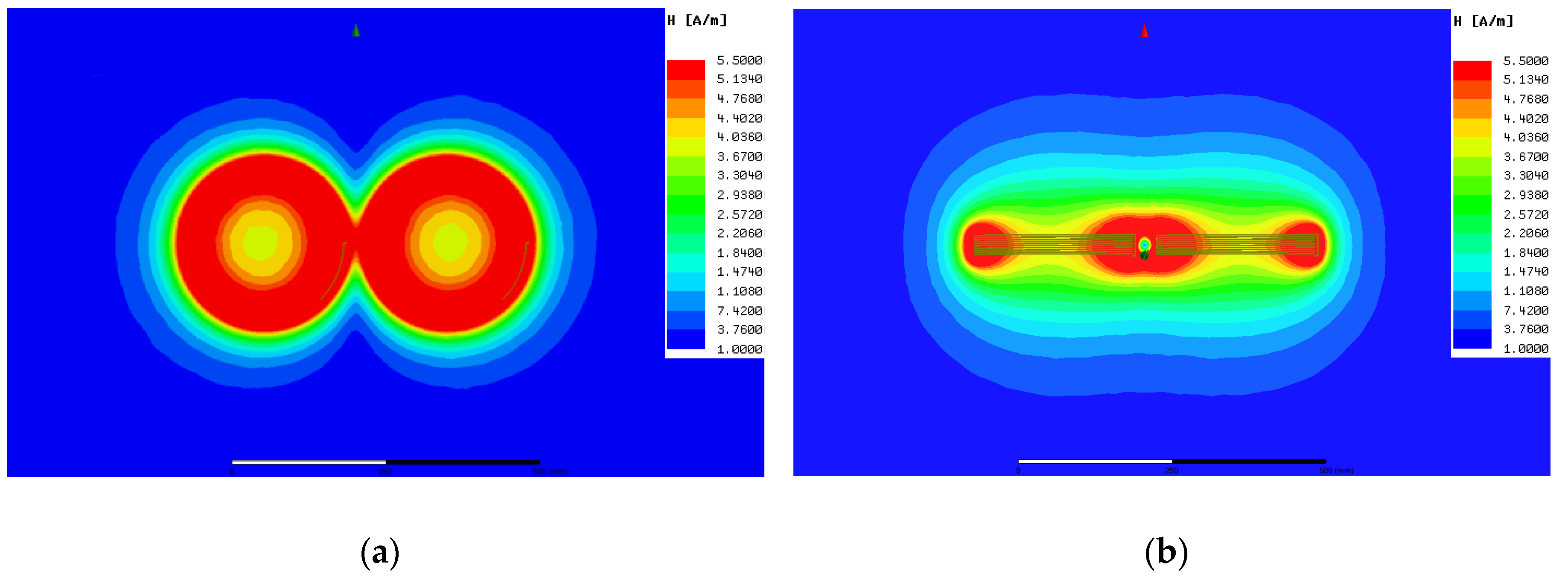
2.2. Magnetic Field Distribution of Coplanar Coils

In order to observe the magnetic field distribution and coupling strength of coplanar coils, an ANSYS Maxwell simulation (EM16.1, ANSYS, Canonsburg, PA, USA) was carried out, as shown in Figure 3, where rS = rP = 20 cm, h = 5 cm, and the number of coil turns is 18. From the overhead view, it can be seen that the magnetic field of a single coil is mainly distributed inside the coil. The magnetic field intensity decreases when away from the coil. From the orthographic view, it can be seen that the magnetic field above the coil is open to the external environment. Thus the magnetic field distribution is sensitive to external interferences. The magnetic coupling between coplanar coils mainly happens at the edges of dual coils. Thus, the coupling strength of a coplanar coil is weaker than that of a coaxial one. However, according to the following calculations and measurements, the mutual inductance is still large enough to transfer power efficiently.

3. Proposed Control Strategy

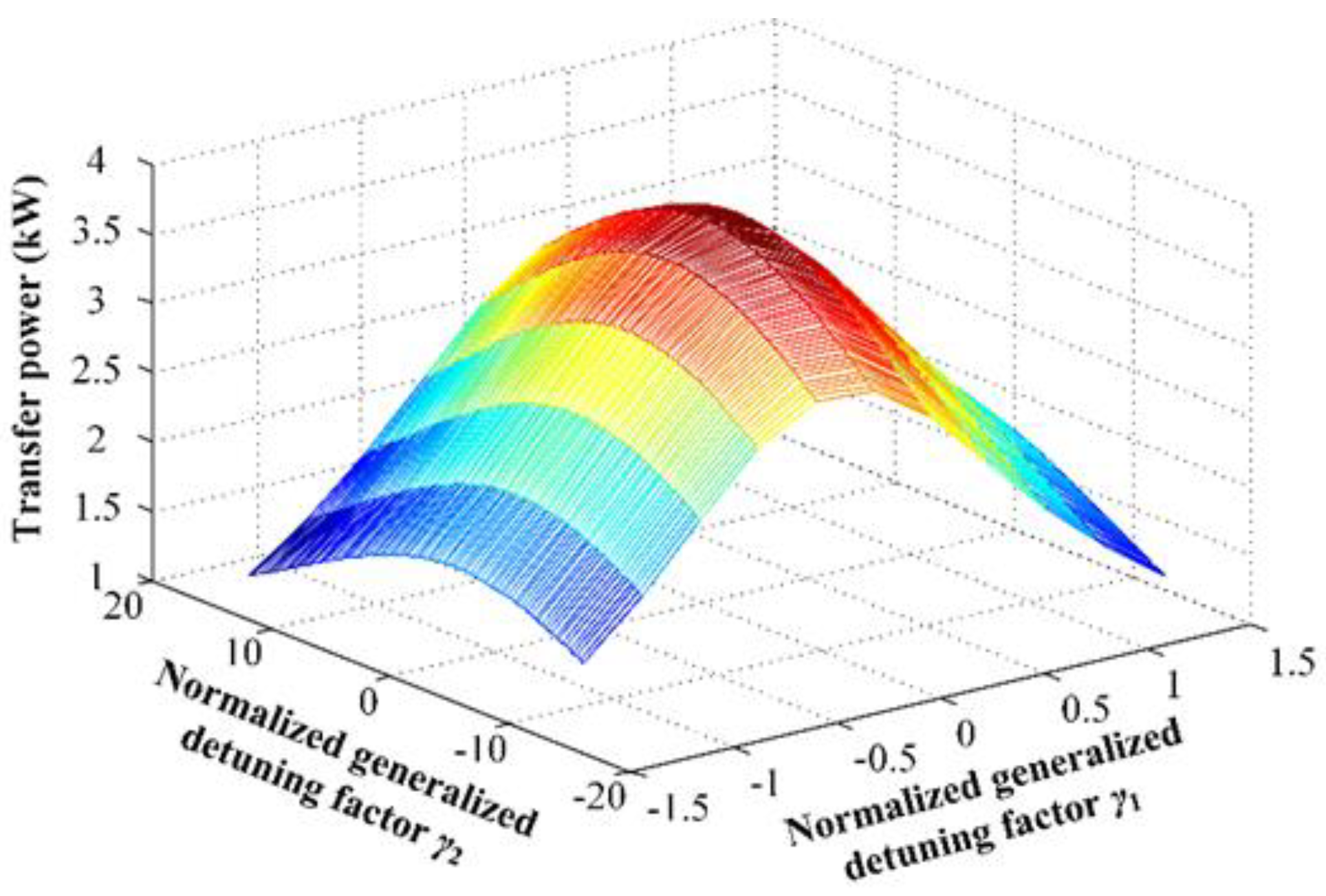
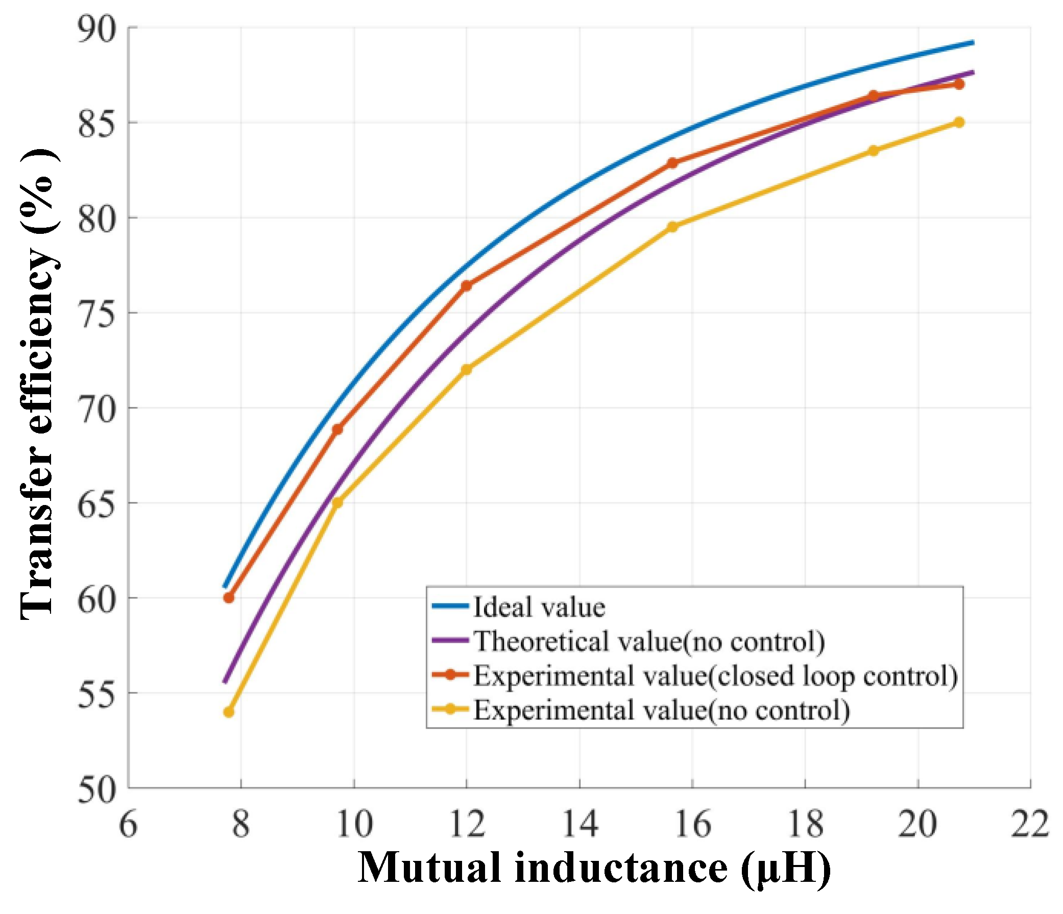
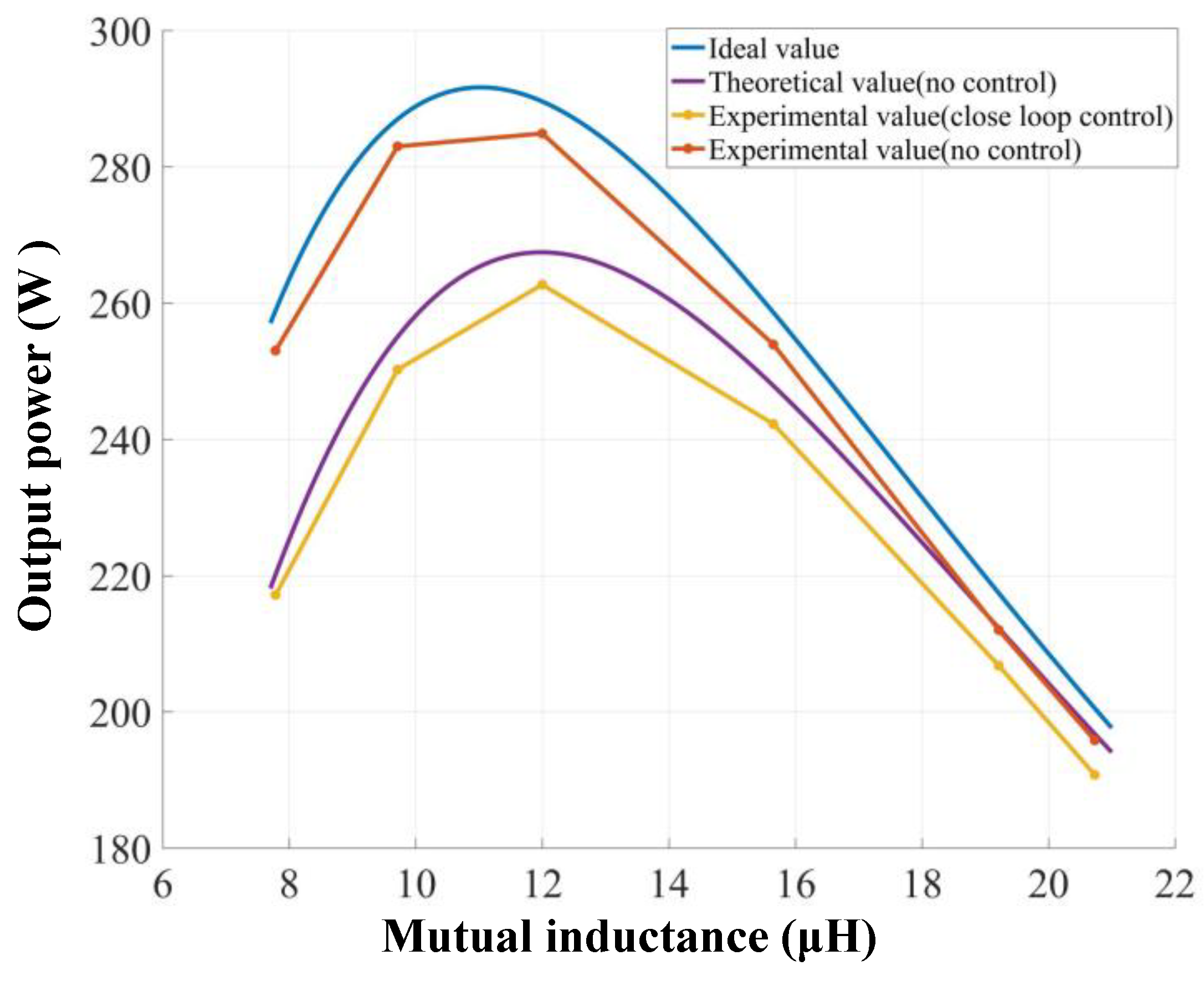
3.1. Effect of Frequency Detuning on Output Power and Transfer Efficiency

Inductances of coils are easily affected in the actual working environment [7,20]. When a metal object or closed conductor is close to an energized coil, the metal object or the close conductor generate an eddy current. That is to say, part of the coil’s magnetic field is absorbed. Thus, the inductance of the coil decreases correspondingly. When a ferromagnetic object is close to an energized coil, the ferromagnetic object changes the magnetic path of the coil’s magnetic field. The magnetic flux leakage of the coil will increase or decrease. Whether the leakage flux increases or decreases depends on the relative position of the ferromagnetic object and the coil. Thus, the inductance of the coil decreases or increases correspondingly. Capacitances of compensation capacitors are also sensitive to working conditions, such as temperature, frequency, bias voltage, etc. Frequency detuning occurs when inductances and capacitances deviate from the ideal values. In this section, the effect of frequency detuning on output power and transfer efficiency is discussed.
In order to reflect the degree of frequency detuning and simplify the analysis, the normalized detuning factors γ is defined as follows:
γ 1 = ( ω L 1 1 ω C 1 ) R 1 = Q 1 ( ω ω 1 ω 1 ω )
γ 2 = ( ω L 2 1 ω C 2 ) R 2 + R L = Q 2 ( ω ω 2 ω 2 ω )
where ω is the angular frequency of the source; ω1, ω2 are the inherent resonant angular frequency of the primary resonant tank and the secondary resonance tank respectively; Q1, Q2 are the quality factors of the primary and secondary resonant tank respectively. ω1,2 and Q1,2 can be expressed as Equations (7)–(9):
ω 1 , 2 = 1 L 1 , 2 C 1 , 2
Q 1 = ω 1 L 1 R 1
Q 2 = ω 2 L 2 R 2 + R L
Thus, γ1, γ2 are positively associated with ω1, ω2, respectively, and γ1, γ2 will be zero when the source frequency is equal to the inherent frequency of the primary and secondary side. According to Kirchhoff’s voltage law (KVL), the equivalent circuit of MRC-WPT system can be described as:
[ R 1 ( 1 + j γ 1 ) j ω M j ω M ( R L + R 2 ) ( 1 + j γ 2 ) ] [ I ˙ 1 I ˙ 2 ] = [ U ˙ S 0 ]
Solving Equation (10), the currents of primary side and secondary side can be obtained:
I ˙ 1 = ( R 2 + R L ) ( 1 + j γ 2 ) U ˙ S R 1 ( R 2 + R L ) ( 1 + j γ 1 ) ( 1 + j γ 2 ) + ( ω M ) 2
I ˙ 2 = j ω M U ˙ S R 1 ( R 2 + R L ) ( 1 + j γ 1 ) ( 1 + j γ 2 ) + ( ω M ) 2
Thus, the output power of MCR-WPT system can be derived as
P o = I 2 2 R L = ( ω M ) 2 U S 2 R L [ R 1 ( R 2 + R L ) ( 1 γ 1 γ 2 ) + ( ω M ) 2 ] + [ R 1 ( R 2 + R L ) ( γ 1 + γ 2 ) ] 2
The relationship between the output power and detuning factors of dual sides is shown in Figure 4, where the MCR-WPT system is under coupling. It can be seen that the output power reach its maximum at γ1 = γ2 = 0 and decreased rapidly as γ1, γ2 deviating away from zero. Thus, the output power will deviate from the rated value when frequency detuning occurs. When the system is over coupled, frequency splitting will occur [21]. The same as the condition of under coupling, the output power will also vary with frequency detuning.
Additionally, the transfer efficiency can be derived as:
η S = I 2 2 R L I 2 2 R L + I 2 2 R 2 + I 1 2 R 1 = ( ω M ) 2 R L ( ω M ) 2 ( R 2 + R L ) + R 1 ( R 2 + R L ) 2 ( 1 + γ 2 2 )
It can be seen that transfer efficiency is inversely associated with γ 2 2 . Transfer efficiency reaches its maximum when γ2 is equal to zero, as shown in Figure 5. As the γ 2 2 increases, the transfer efficiency decreases rapidly. The parameters in Figure 4 and Figure 5 are both taken from Table 1.
According to the analysis above, frequency detuning adversely affects both the transfer efficiency and output power of MCR-WPT systems. Therefore, a corresponding control strategy must be applied to eliminate the frequency detuning.

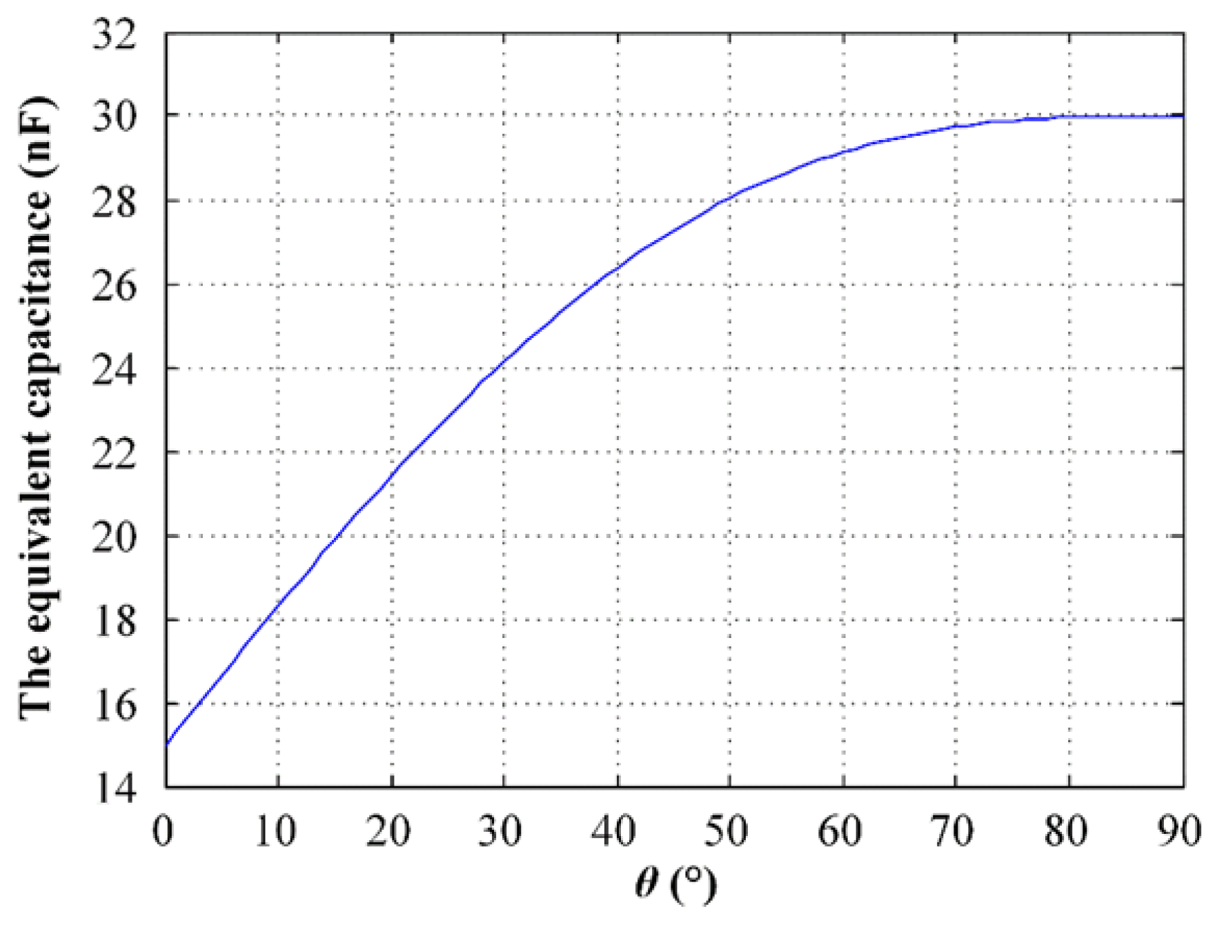
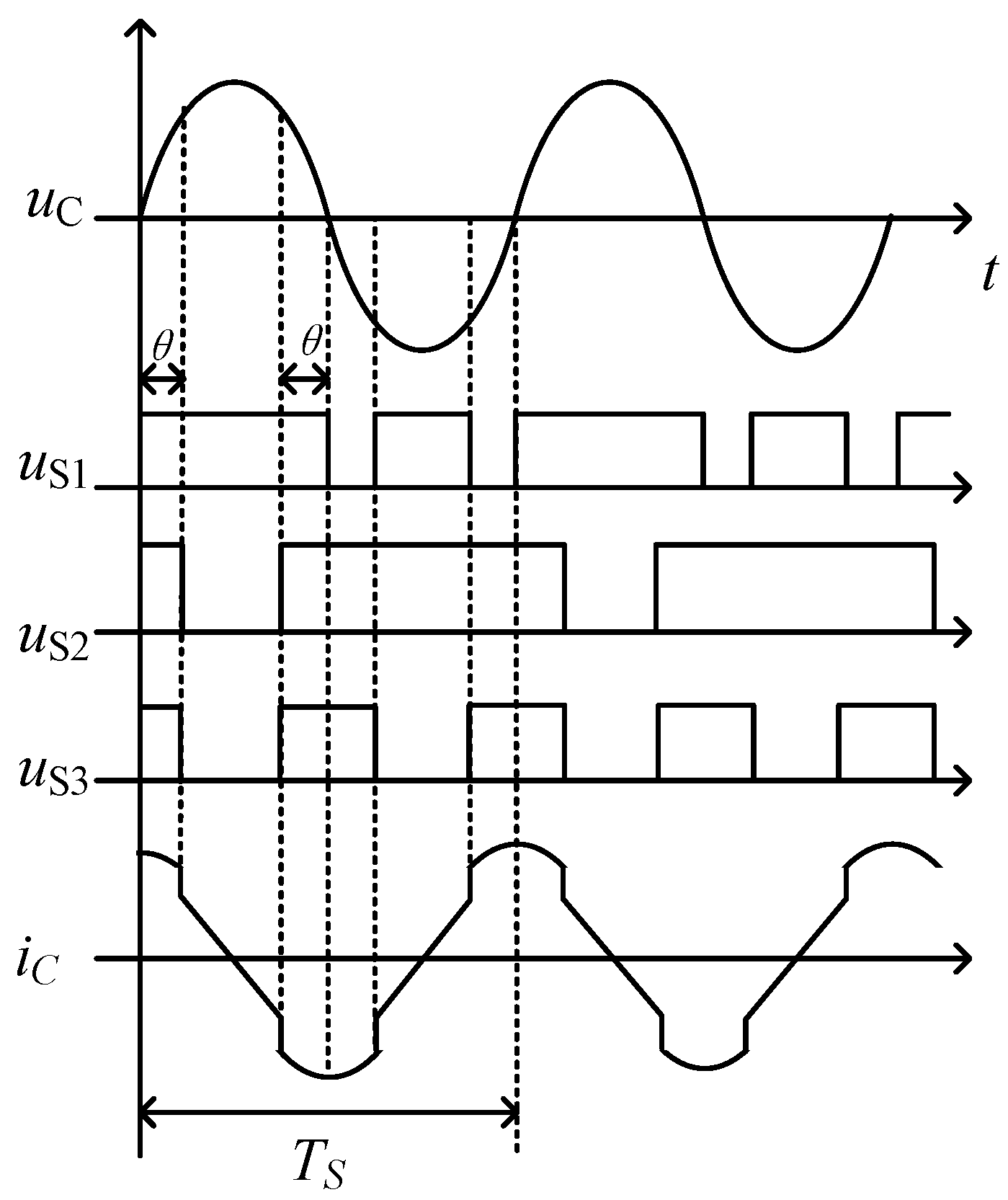
3.2. Dual-Side Switched Capacitor Control Strategy

In the proposed dual-side independent switched capacitor control for eliminating frequency detuning, the capacitances of primary side and secondary side can be adjusted. Thus, the inherent frequency tracks the source frequency all the time. The dual-side control strategies proposed in previous papers usually need to add wireless communication devices [7], which increases the cost of the system and easily leads to system instability. In order to remove wireless communication devices, the proposed control strategy implemented on both sides independently. That is to say, the proposed control strategy does not require data communication between the sides. There are two principles should be obeyed by primary side and secondary side respectively in the proposed control strategy:
(1)
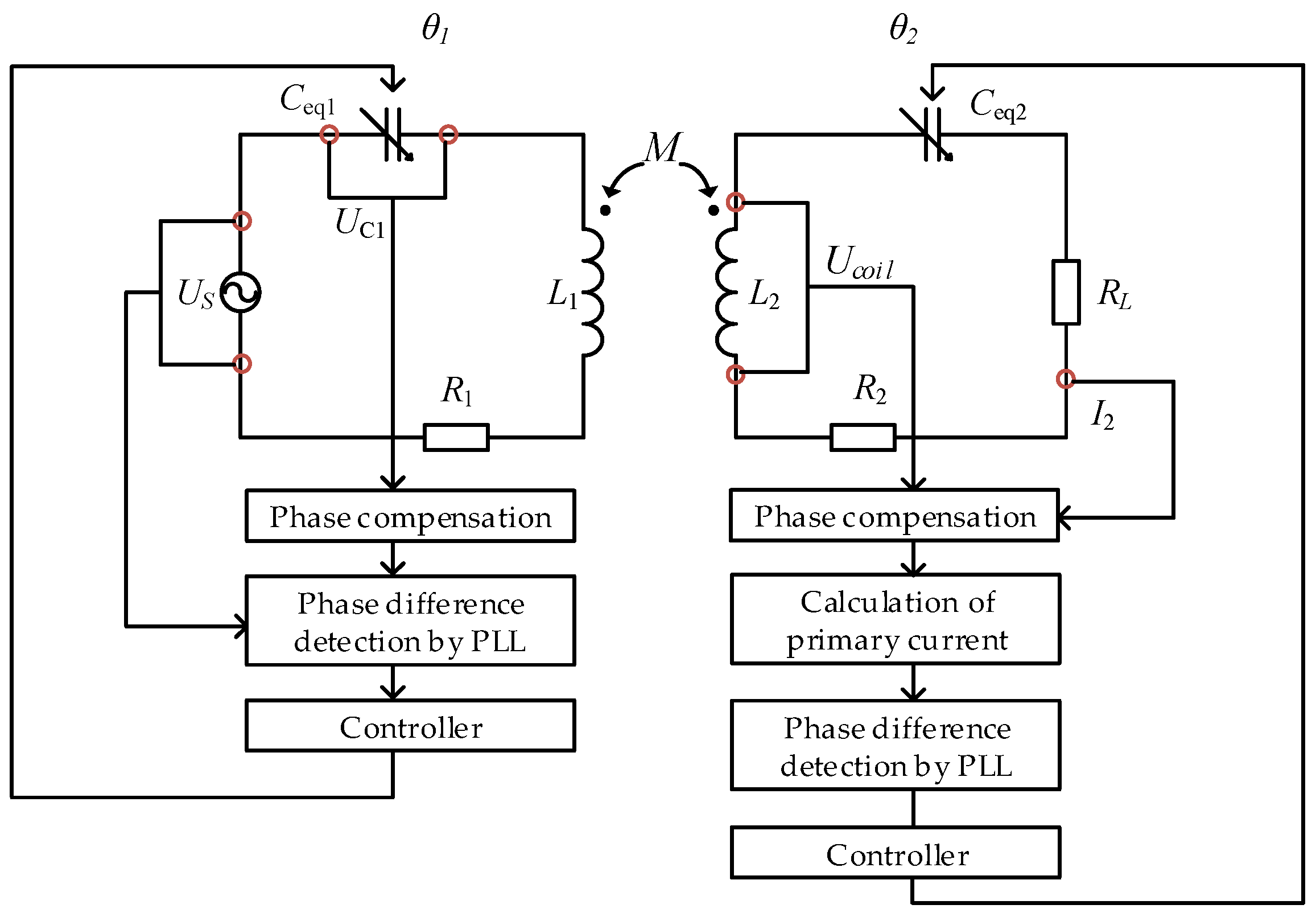
Primary side: keep the phase difference between source voltage and capacitor voltage of primary side at 90°.
(2)
Secondary side: keep the phase difference between secondary current and primary current at 90°.
We consider the former principle first. According to Equation (10), the phase difference between source voltage and capacitor voltage of primary side can be obtained:
U ˙ S U ˙ C 1 = [ R 1 ( 1 + j γ 1 ) + ω 2 M 2 ( R 2 + R L ) ( 1 + j γ 2 ) ] j ω C 1 = R 1 γ 1 ω C 1 + ( ω M ) 2 γ 2 ω C 1 ( R 2 + R L ) ( 1 + γ 2 2 ) + j [ ω C 1 R 1 + ω C 1 ( ω M ) 2 ( R 2 + R L ) ( 1 + γ 2 2 ) ]
The real part of Equation (15) will be zero if the phase difference between source voltage and capacitor voltage of primary side is 90°. In that case, the capacitance of primary side is derived as follows:
C 1 = 1 ( ω 2 L 1 ( ω M ) 2 ω γ 2 ( R 2 + R L ) ( 1 + γ 2 2 ) )
Then we consider the latter principle. In order to cancel the communication between both sides, the primary current should be calculated according to the quantity received from secondary. The primary current is reflected in the induced electromotive force of the secondary side, which is included in the voltage of the secondary coil. The voltage of the secondary coil can be described as Equation (17). Hence, the primary current can be calculated from the secondary current and coil voltage using Equation (18). According to Equation (10), when the secondary side is resonant at the source frequency, the relationship between the primary current and secondary current can be described as Equation (19):
U ˙ c o i l = ( R 2 + j ω L 2 ) I ˙ 2 j ω M I ˙ 1
j ω M I ˙ 1 = ( R 2 + j ω L 2 ) I ˙ 2 U ˙ c o i l
j ω M I ˙ 1 = R 2 I ˙ 2
Therefore, the secondary side can keep the inherent frequency equal to the source frequency if the phase difference between the secondary current and primary current is kept at 90°. Then, the primary capacitor can be obtained when we substitute γ2 = 0 into Equation (16).

3.3. Control Scheme

Figure 6 shows the schematic diagram of a switched capacitor [13]. The capacitor Cr is in series with the circuit to reduce the voltage stress of the switches. Cs is in parallel with the switch and plays the role of a stabilizing voltage. The main waveforms of the switched capacitor are shown in Figure 7, where uS1, uS2, uS3 is the signal of switch S1, S2 and S3 respectively.
Thus, the relationship between fundamental current of capacitor IC and fundamental voltage of capacitor UC can be described as follows:
I C = ω C e q U C
IC can be written by Fourier expansion:
I C = ( 2 θ C r 2 + C r 2 sin 2 θ + π C r C s ) ω U C π C s + π C r
Therefore, the equivalent switched capacitance can be derived as:
C e q = 2 θ C r 2 + C r 2 sin 2 θ + π C r C s π C s + π C r
The equivalent capacitance adjusts with the change of phase shift angle θ. It can be seen the equivalent capacitance is proportional to θ. The minimum and maximum value of the equivalent capacitance can be obtained at θ = 0° and θ = 90°, which are (Cr + Cs)/CrCs and Cr, respectively. When Cr = Cs = 30 nF, the equivalent capacitance of the switched capacitor is shown in Figure 8.
Based on the analysis above, the scheme of proposed control strategy is shown in Figure 9. In the diagram, θ1 and θ2 are the controlled quantities of the primary side and secondary side, respectively. The equivalent capacitances can be controlled by adjusting the value of θ1 and θ2.
On the primary side, a D class power amplifier is selected as the inverter of the proposed WPT system. The resonant tank of a D class power amplifier usually adopts an inductor-capacitor series resonant network. The resonant tank should be inductive slightly to achieve soft switching [2]. Both the source voltage us and the capacitor voltage uc1 are detected by the voltage sensors. Then the phase compensation is implemented to compensate the delay time resulting from sampling. In addition, the phase of the source voltage should be compensated a little more to realize soft switching. By feeding the source voltage and capacitor voltage into the PLL phase detector, the phase difference can be obtained. Then, θ1 is adjusted by the Digital Signal Processing (DSP) controller according to the phase difference. Thus, a Pulse Width Modulation (PWM) signal is generated to drive the switches. On the secondary side, the coil voltage is detected by voltage sensors, and the secondary current is detected by closed loop Hall sensors. Then the phase compensation is implemented to compensate the delay time coming from sampling. The primary current can be calculated utilizing coil voltage and secondary current according to Equation (18). Thus, the phase difference of the secondary current and primary current can be controlled as 90°, the same as the primary side does. The logic of the control strategy is depicted in the flowchart of Figure 10 and the specific analysis is as follows:
(1)
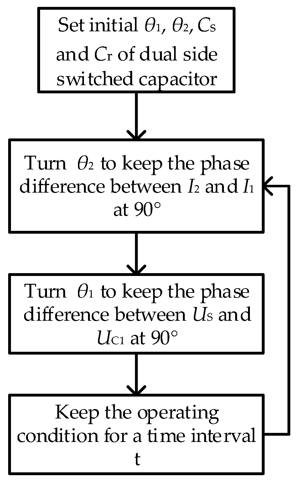
The initial equivalent capacitance of the switched capacitor should be set before the system starts. That is, the initial value of θ1, θ2, Cs and Cr should be set first. Firstly, the initial equivalent capacitance needs to ensure that the inherent frequency of the resonant tank is equal to the source frequency, where the inductances of both sides are measured accurately. Secondly, θ1 and θ2 are set in an intermediate value among the whole adjustable range. Then the switched capacitor can track the source frequency no matter whether the inductance increases or decreases in the working environment. For convenience, the initial θ1 and θ2 are set at the same value, so as to obtain Cr and Cs of both sides.
(2)
For the secondary side, θ2 is adjusted by the PLL control module to track the 90° phase difference between the primary current and the secondary current. Thus, γ2 is equal to zero and the inherent frequency of the secondary resonant tank is identical to the source frequency.
(3)
For the primary side, θ1 is adjusted by the PLL control module to track the 90° phase difference between the source voltage and the capacitance voltage of the primary side. Thus, Ceq1 is equal to 1/( ω 2 L 1 ) and the inherent frequency of the primary resonant tank is identical to the source frequency.
(4)
Keep the operating condition for a time interval t. After this time interval, the control system will work again.
Actually, step 2 and step 3 do not work in order. That is, the switched capacitors of both sides are controlled independently.

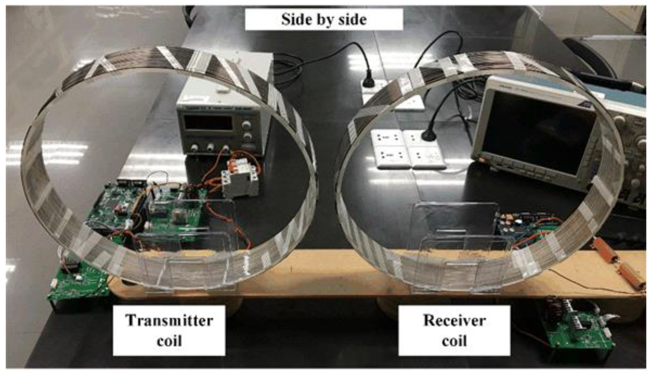
4. Experimental Validation

In order to verify the accuracy of the mutual inductance formula and the feasibility of the proposed control method, an experiment is performed. The experimental system is shown in Figure 11. The frequency of the power supply is 50 kHz. The Metal-Oxide-Semiconductor Field-Effect Transistors (MOSFETs) of the D class power amplifier and switched capacitors are IRF640 (VISHAY, Malvern, PA, USA). The control units of both sides are TMS320F28335 (Texas Instruments, Inc, Dallas, TX, USA). The type of Hall current sensors are LTS6-NP (LEM, Geneva, Switzerland). The parameters of the transfer coils of bot sides and the electric parameters of the system are shown in Table 1.

4.1. Mutual Inductance Experiment

The mutual inductance of coplanar coils can be designed based on the formula proposed in Section 2. In order to verify the accuracy of the formula, the mutual inductances under different distances between two coils are measured, as shown in Figure 12. It can be seen that the mutual inductance formula has high accuracy when the distance h is large enough. The error between calculation and measurement is inversely associated with h. However, the error is located in an acceptable range. The experimental results and theoretical values are in the same order of magnitude. Therefore the formula possesses guiding significance for the design of mutual inductance.

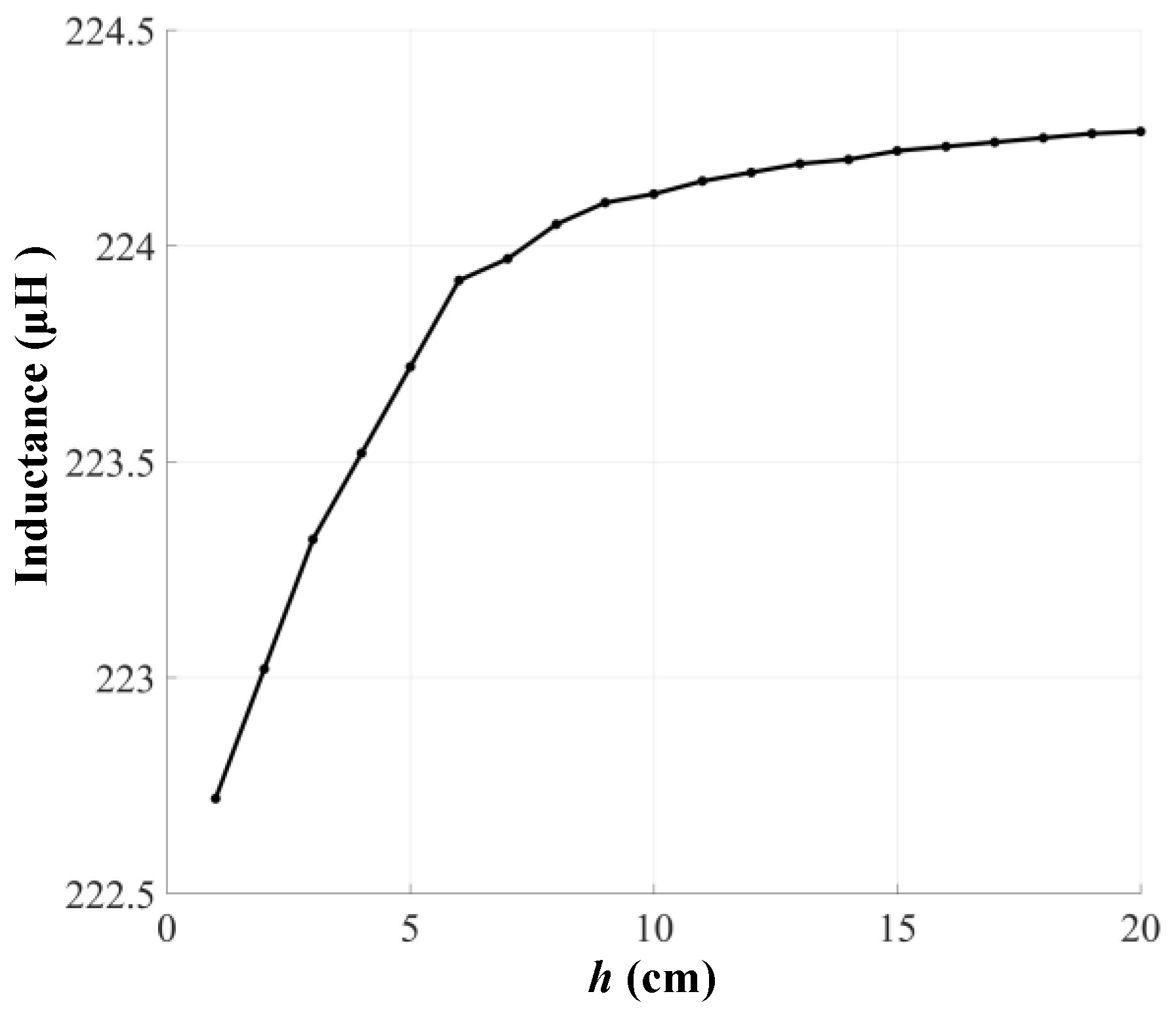
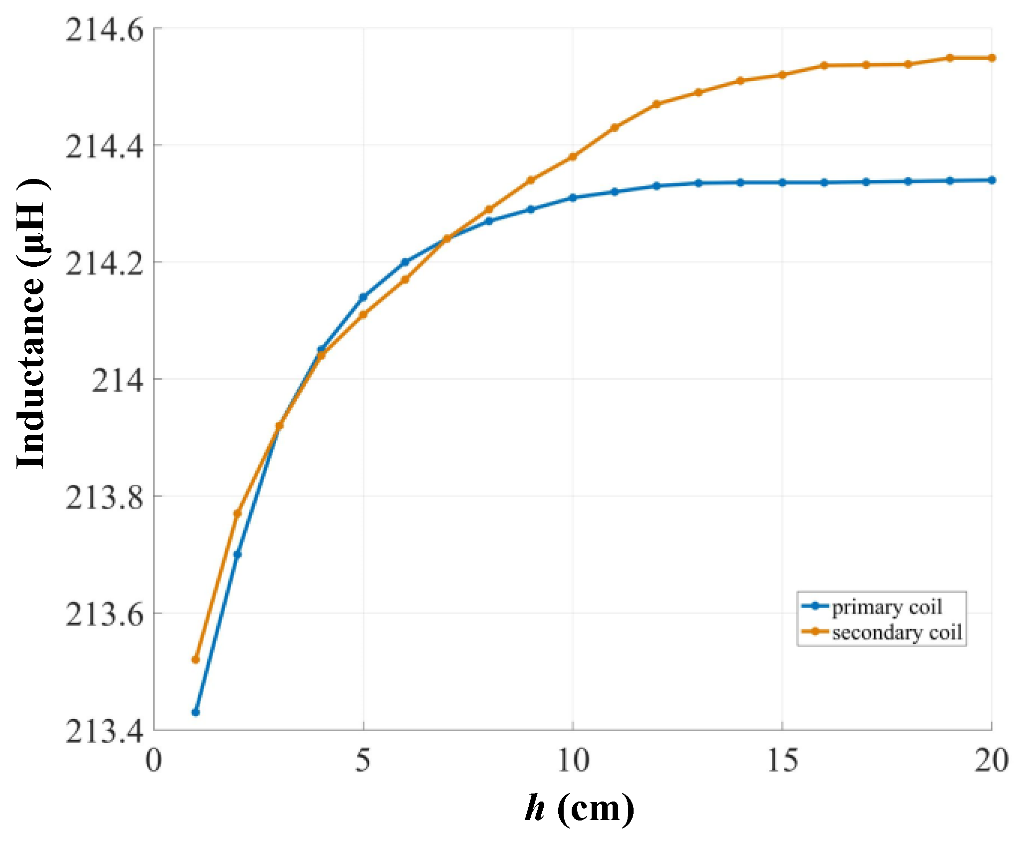
4.2. Measurement of Coil Inductance

As mentioned in the previous part, the inductance of a coil is affected by external interferences. In order to illustrate the influence of interferences intuitively, the coil inductance is measured under different conditions. As can be seen in the Table 1, the inductances of the primary coil and secondary coil are measured under relatively ideal conditions. That is to say, the coils are separated from all the surrounding objects more than 30 cm except the impedance analyzer. Thus, these measured values are relatively accurate. The inductance of the secondary coil in Table 1 is selected as the reference value. Meanwhile, the secondary coil is used as the object to be measured under different conditions.
First, the interaction between two coils is measured. The primary coil is close and placed next to secondary coil as the only source of interference. The inductances are measured with different distances between the coils as shown in Figure 13. When the two coils are close to each other, the inductance of the secondary coil decreases slightly. Secondly, the effect of metal objects on the coil inductance is measured. A 10 cm × 10 cm × 1.05 cm foil is selected as the only source of interference and placed at the center of the coil. The measurement result of 212.5 μH. It can be seen that the metal object reduces the inductance of the coil. Finally, the effect of ferromagnetic objects on the coil inductance is measured. A circular ferrite core is selected as the only source of interference and placed at the center of the coil. The outside diameter, inside diameter, and thickness of the core are 12 cm, 6.5 cm, and 3.5 cm, respectively. The measurement result is 232.5 μH. Due to the decrease of leakage flux, the inductance increases compared to the reference value.

4.3. Verification of the Proposed Control Strategy

In order to verify that the proposed control strategy can eliminate frequency detuning, the coils of the experimental system should be placed in an environment full of interference. Therefore, the experimental system is laid on a workbench with a metal cupboard underneath. Thus, the inductances of two coils deviate from the reference value. The inductances of the primary coil and secondary coil are shown in Figure 14.
Both experiments under no control and under closed loop control have been carried out to verify the validity of the proposed control strategy. As to the experimental system without control, fixed compensation capacitors are used for the purpose of comparison. Their values, which are 45 nF, can be obtained by Equation (5). As to the experimental system with closed loop control, the initial θ1 and θ2 are set to 45°. Thus, the initial equivalent capacitances are 45 nF and resonant with inductance of coils. According to the analysis in Section 3.3, the adjustable range of the switched capacitor is (30 nF, 60 nF). That is to say, the proposed control strategy can deal with frequency detuning as long as the range of inductance does not exceed 168.9 μH to 337.74 μH.
For the experiment under closed loop control, the output voltage of inverter US, capacitor voltage of primary side UC1 and the voltage of load URL are shown in Figure 15. It can be seen that the phase difference between US and UC1 is 90° with variable distance of the coplanar coils. The phase difference between the primary current and the secondary current can be obtained from the phase difference between URL and UC1. The phase of URL is equal to the phase of secondary current and the phase difference between the primary current and UC1 is 90°. The phase difference between URL and UC1 is 0 with variable distance of coplanar coils according to Figure 13. Therefore, the phase difference between the primary current and the secondary current is always 90°. Hence, the proposed control strategy can be achieved by the experimental system.
Then, the transfer efficiencies of the experimental system without control and with closed loop control are shown in Figure 16. The output powers are shown in Figure 17. It is noted that the losses produced by switched capacitors are taken into account when measuring the efficiency. For the purpose of comparison, the ideal value of transfer efficiency is also shown in Figure 16 and the ideal value of output power is shown in Figure 17. The ideal value of transfer efficiency can be calculated according to Equation (14) with zero γ2. The ideal value of output power can be calculated according to (13) with zero γ1 and γ2. Furthermore, the transfer efficiencies and the output powers under this set of parameters are shown in Figure 16 and Figure 17. According to the comparison between the ideal value and the theoretical value under no control, frequency detuning reduces the transfer efficiency and output power severely. The transfer efficiency under ideal conditions is about 5% higher than that under frequency detuning. The output power under ideal conditions is about 40 W higher than that under frequency detuning at worst. The transfer efficiency and output power under closed loop control are lower than the ideal value slightly, which is due to the additional losses of switched capacitors. It is obviously that the system with proposed control strategy performs better than that without control. When h takes 5 cm, the experimental transfer efficiency under closed loop control is 76.37% and output power is 285.66 W. In comparison, the experimental transfer efficiency under no control is 72.21% and output power is 271.37 W. When h takes 10 cm, the experimental transfer efficiency under closed loop control is 60.2% and output power is 257.2 W. In comparison, the experimental transfer efficiency under no control is 53.8% and output power is 216.7 W. In summary, the proposed control strategy can practically eliminate frequency detuning. Apart from the deviation of inductance, this control strategy can also solve the deviation of capacitance caused by bias voltage, temperature rise, design error, etc.

5. Conclusions

A MCR-WPT system with coplanar coils is proposed in this paper. Compared to traditional coils arranged coaxially, coplanar coils are arranged in the same plane which can save more space. The mutual inductance and magnetic field distribution between the coils of dual sides are analyzed. The formula of mutual inductance can be obtained and verified by experimental measurements. The MCR-WPT with coplanar coils is more sensitive to the interference caused by external electromagnetic fields and foreign objects so that the inductance can be changed easily. In order to deal with this problem, a dual-side independent switched capacitor control strategy is proposed in this paper. Analyses and experiments have been carried out to verify the effectiveness of the control strategy. The transfer efficiency improves remarkably with the proposed control strategy. The advantage of this method is that it does not need to change the source frequency, so the applicability of the system is increased when concerned about frequency standard. What’s more, since both sides of the system are controlled, the performance of efficiency and output power is better that that of a system with one side control.

Author Contributions

C.H. established the model, analyzed the characteristics of the proposed model, implemented the experimental and wrote this article; Z.F. designed the parameters and performed the simulations; B.Z., W.X., D.Q. and Y.C. guided and revised the paper.

Funding

This project was supported by the Key Program of National Natural Science Foundation of China (Grant No. 51437005), Natural Science Foundation of Guangdong Province, China (Grant No. 2016A030313515) and National Natural Science Foundation of China (Grant No. 51677074).

Conflicts of Interest

The authors declare no conflict of interest.

References

  1. Kurs, A.; Karalis, A.; Moffatt, R.; Joannopoulos, J.D.; Fisher, P.; Soljacic, M. Wireless power transfer via strongly coupled magnetic resonances. Science 2007, 317, 83–86. [Google Scholar] [CrossRef] [PubMed]
  2. Li, Z.; Zhu, C.; Jiang, J.; Song, K.; Wei, G. A 3-kw wireless power transfer system for sightseeing car supercapacitor charge. IEEE Trans. Power Electron. 2017, 32, 3301–3316. [Google Scholar] [CrossRef]
  3. Liu, S.; Liu, M.; Yang, S.; Ma, C.; Zhu, X. A novel design methodology for high-efficiency current-mode and voltage-mode class-e power amplifiers in wireless power transfer systems. IEEE Trans. Power Electron. 2017, 32, 4514–4523. [Google Scholar] [CrossRef]
  4. Imura, T.; Hori, Y. Maximizing air gap and efficiency of magnetic resonant coupling for wireless power transfer using equivalent circuit and neumann formula. IEEE Trans. Ind. Electron. 2011, 58, 4746–4752. [Google Scholar] [CrossRef]
  5. Zhang, W.; Zhang, T.; Guo, Q.; Shao, L.; Zhang, N.; Jin, X.; Yang, J. High-efficiency wireless power transfer system for 3D, unstationary free-positioning and multi-object charging. IET Electric Power Appl. 2018, 12, 658–665. [Google Scholar] [CrossRef]
  6. Liu, D.; Hu, H.; Georgakopoulos, S.V. Misalignment sensitivity of strongly coupled wireless power transfer systems. IEEE Trans. Power Electron. 2017, 32, 5509–5519. [Google Scholar] [CrossRef]
  7. Gati, E.; Kampitsis, G.; Manias, S. Variable frequency controller for inductive power transfer in dynamic conditions. IEEE Trans. Power Electron. 2017, 32, 1684–1696. [Google Scholar] [CrossRef]
  8. Fu, W.; Zhang, B.; Qiu, D. Study on Frequency-tracking Wireless Power Transfer System by Resonant Coupling. World Invert. 2009, 8, 41–46. [Google Scholar] [CrossRef]
  9. Ahn, D.; Hong, S. Wireless power transmission with self-regulated output voltage for biomedical implant. IEEE Trans. Ind. Electron. 2014, 61, 2225–2235. [Google Scholar] [CrossRef]
  10. Lim, Y.; Tang, H.; Lim, S.; Park, J. An adaptive impedance-matching network based on a novel capacitor matrix for wireless power transfer. IEEE Trans. Power Electron. 2014, 29, 4403–4413. [Google Scholar] [CrossRef]
  11. Kim, J.; Kim, D.H.; Park, Y.J. Free-positioning wireless power transfer to multiple devices using a planar transmitting coil and switchable impedance matching networks. IEEE Trans. Microw. Theory Tech. 2016, 64, 3714–3722. [Google Scholar] [CrossRef]
  12. Tian, J.; Hu, A.P. A dc-voltage-controlled variable capacitor for stabilizing the zvs frequency of a resonant converter for wireless power transfer. IEEE Trans. Power Electron. 2017, 32, 2312–2318. [Google Scholar] [CrossRef]
  13. Jiang, Y.; Zhang, B. A high power fractional-order capacitor with 1 < α < 2 based on power converter. IEEE Trans. Ind. Electron. 2017, 65, 3157–3164. [Google Scholar] [CrossRef]
  14. Iguchi, S.; Yeon, P.; Fuketa, H.; Ishida, K.; Sakurai, T.; Takamiya, M. Wireless power transfer with zero-phase-difference capacitance control. IEEE Trans. Circuits Syst. I Regul. Pap. 2015, 62, 938–947. [Google Scholar] [CrossRef]
  15. Technical Information Report SAE J2954; RP Draft; Society of Automotive Engineers: Warrendale, PA, USA, 2016.
  16. Nguyen, M.Q.; Woods, P.; Hughes, Z.; Seo, Y.S.; Rao, S.; Chiao, J.C. A mutual inductance approach for optimization of wireless energy transmission. IEEE Wirel. Microw. Circuits Syst. 2014, 1, 1–4. [Google Scholar] [CrossRef]
  17. Kim, K.B.; Levi, E.; Zabar, Z.; Birenbaum, L. Mutual inductance of noncoaxial circular coils with constant current density. IEEE Trans. Magn. 1997, 33, 4303–4309. [Google Scholar] [CrossRef]
  18. Smythe, W.R. Static and Dynamic Electricity; McGraw-Hill: New York, NY, USA, 1950; pp. 267–271. ISBN 13: 9780070594203. [Google Scholar]
  19. Liu, F.; Yang, Y.; Jiang, D.; Ruan, X.; Chen, X. Modeling and Optimization of Magnetically Coupled Resonant Wireless Power Transfer System with Varying Spatial Scales. IEEE Trans. Power Electron. 2017, 32, 3240–3250. [Google Scholar] [CrossRef]
  20. Huang, C.Y.; James, J.E.; Covic, G.A. Design considerations for variable coupling lumped coil systems. IEEE Trans. Power Electron. 2015, 30, 680–689. [Google Scholar] [CrossRef]
  21. Huang, R.; Zhang, B.; Qiu, D.; Zhang, Y. Frequency splitting phenomena of magnetic resonant coupling wireless power transfer. IEEE Trans. Magn. 2014, 50, 1–4. [Google Scholar] [CrossRef]
Figure 1. Equivalent circuit of Magnetic Coupling Resonant Wireless Power Transfer (MRC-WPT) system.
Energies 11 01472 g001
Figure 2. Schematic of coplanar coils.
Energies 11 01472 g002
Figure 3. Diagram of magnetic field distribution. (a) Overhead view (b) Orthographic view.
Energies 11 01472 g003
Figure 4. Output power versus detuning factors in 3D space.
Energies 11 01472 g004
Figure 5. Transfer efficiency versus detuning factor of secondary side.
Energies 11 01472 g005
Figure 6. Scheme of an adjustable capacitor.
Energies 11 01472 g006
Figure 7. Waveforms of the adjustable capacitor.
Energies 11 01472 g007
Figure 8. The equivalent capacitance versus θ.
Energies 11 01472 g008
Figure 9. Scheme of the dual-side switched capacitor control strategy.
Energies 11 01472 g009
Figure 10. Flowchart of the control strategy.
Energies 11 01472 g010
Figure 11. Experimental setup configuration.
Energies 11 01472 g011
Figure 12. Mutual inductance in theory and experiment.
Energies 11 01472 g012
Figure 13. The secondary coil inductance under interference from the primary coil.
Energies 11 01472 g013
Figure 14. Inductances of the primary coil and secondary coil under different h.
Energies 11 01472 g014
Figure 15. Experimental waveforms of experiment. (a) h = 5 cm (b) h = 10 cm.
Energies 11 01472 g015
Figure 16. Transfer efficiencies under different conditions.
Energies 11 01472 g016
Figure 17. Output powers under different conditions.
Energies 11 01472 g017
Table 1. Parameters of the experimental MCR-WPT system.
ParametersSymbolValue
Voltage of power supply (RMS)Us20 V
Radius of coilr20 cm
Radius of wireWr0.75 mm
Turns of coiln18
Inductance of primary sideL1224.3 μH
Inductance of secondary sideL2224.5 μH
Parallel capacitance of primary sideCs160 nF
Parallel capacitance of secondaryCs260 nF
Series capacitance of primary sideCr160 nF
Series capacitance of secondary sideCr260 nF
ESR of primary sideR1333 mΩ
ESR of secondary sideR2385 mΩ
LoadRL10 Ω

