Study on a Novel Gelled Foam for Conformance Control in High Temperature and High Salinity Reservoirs


Abstract
:1. Introduction
2. Materials and Methods
2.1. Materials
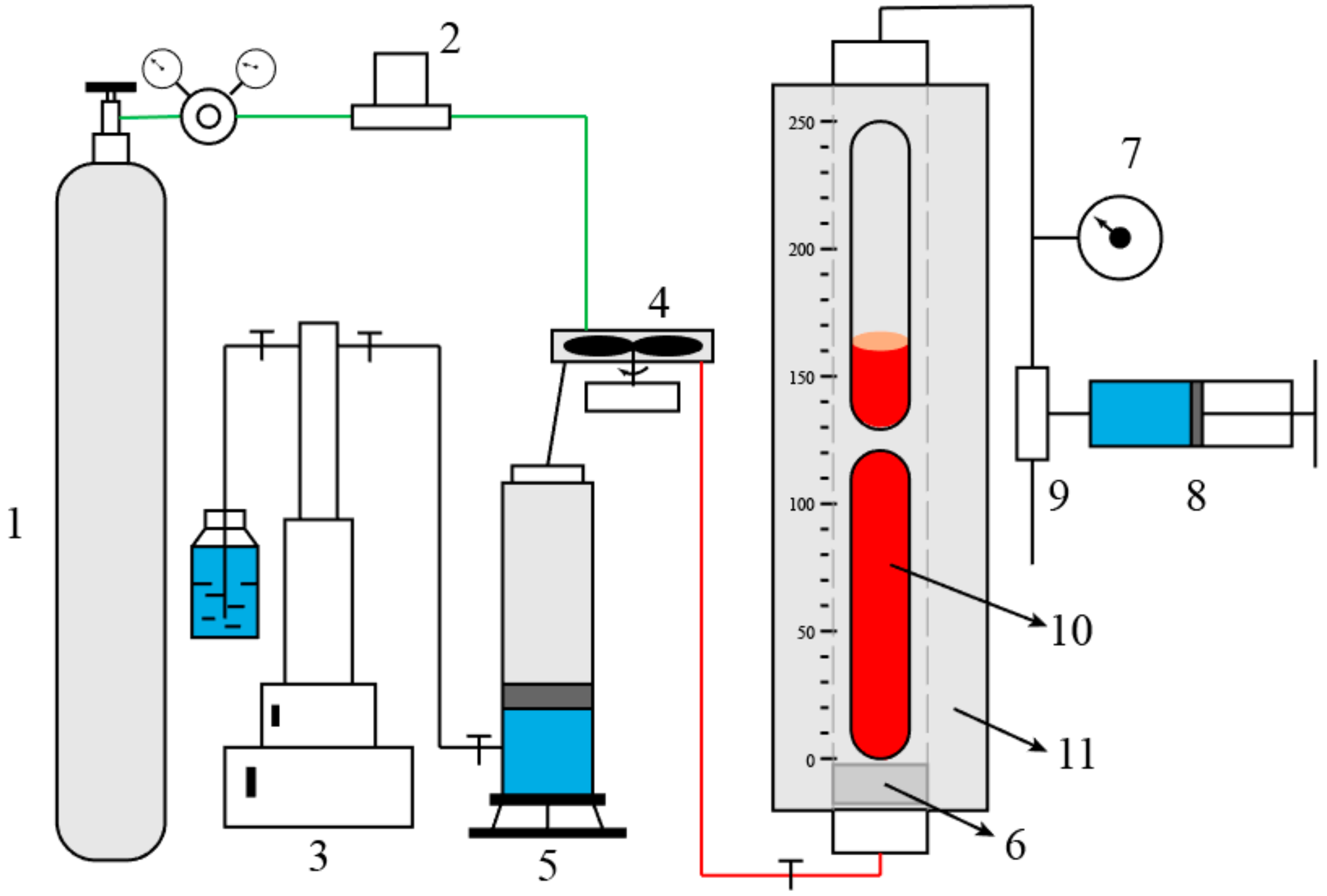
2.2. Measurements of Foaming Performance
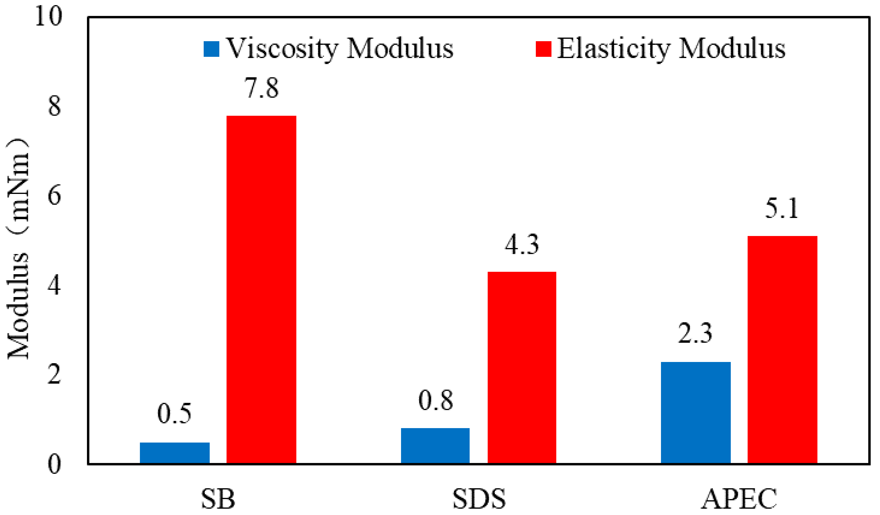
2.3. Measurements of Interfacial Rheology
2.4. Measurements of Gelling Performance
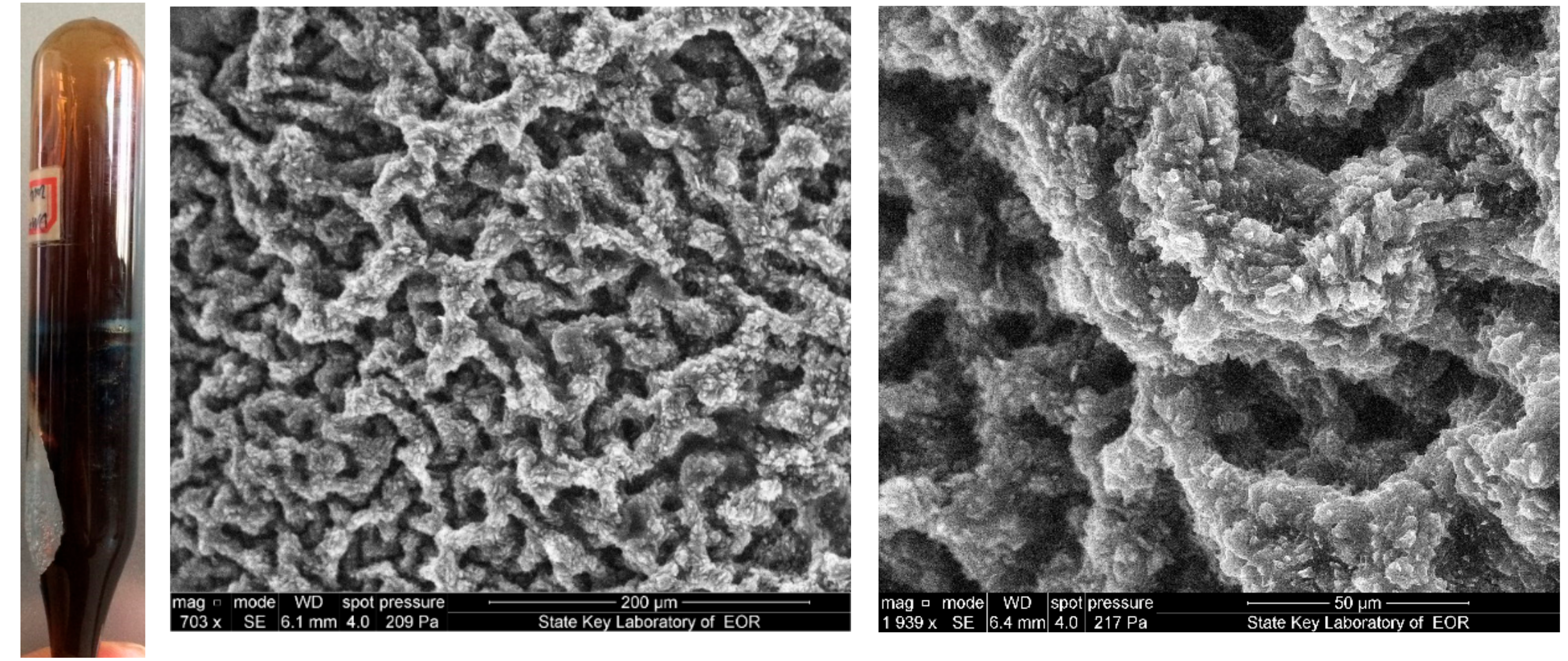
2.5. Measurements of Microstructure
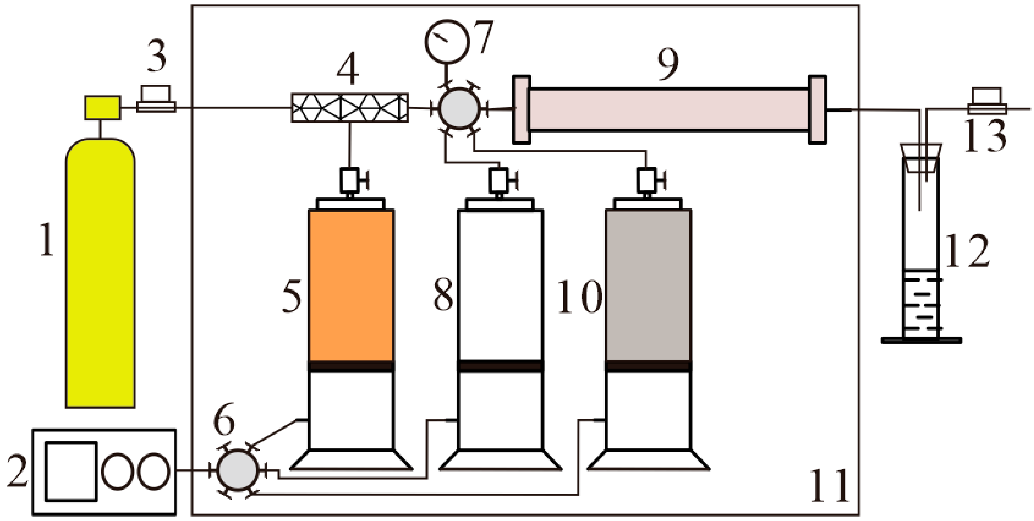
2.6. Core Flooding Experiment
3. Results and Discussion
3.1. Optimization of the Gelled Foam
3.1.1. Optimization of Foaming Agent
Foaming Performance
Interfacial Rheology
3.1.2. Optimization of the Gel
3.1.3. Characterization of Gelled Foam
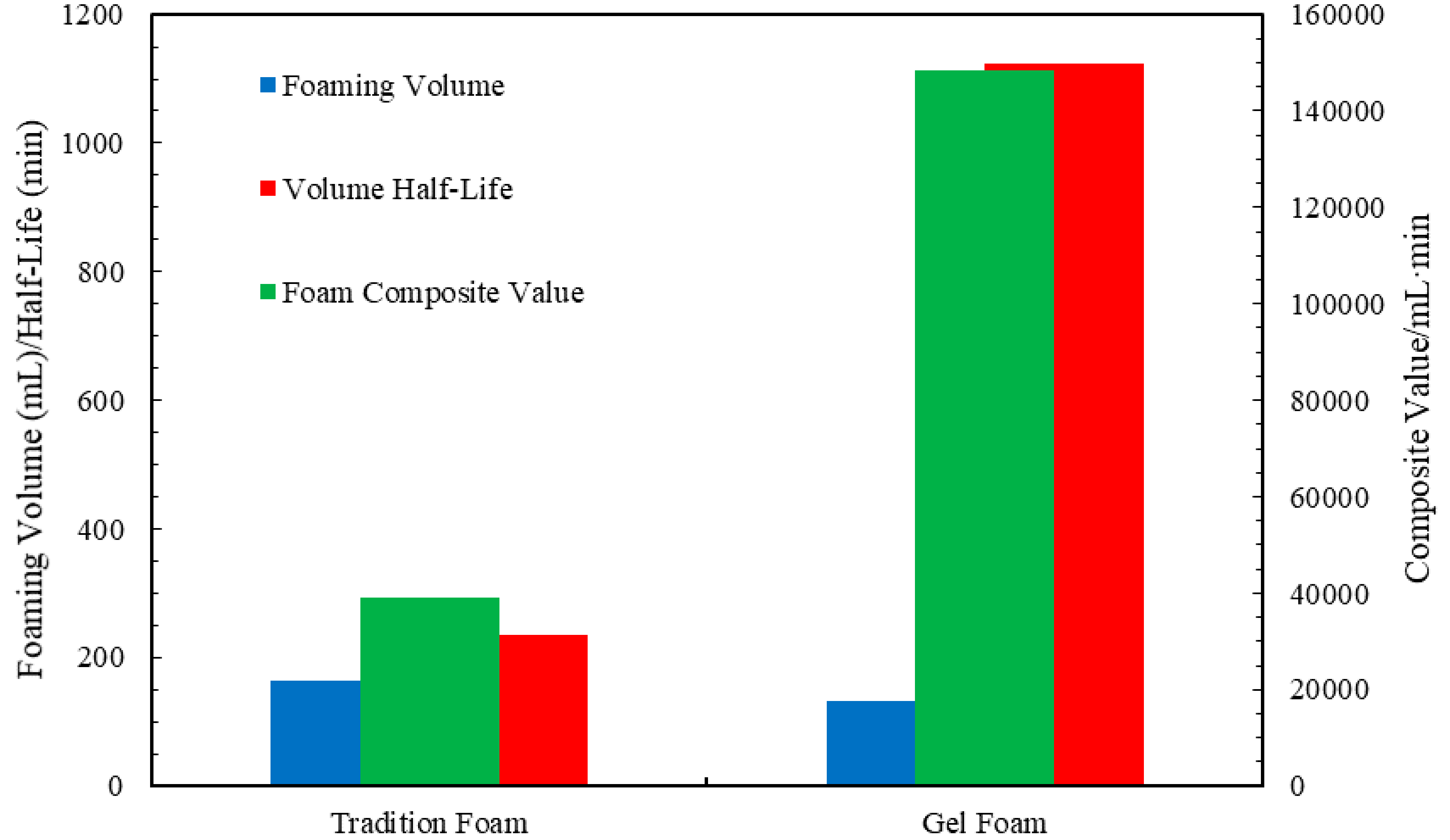
Foaming Performance
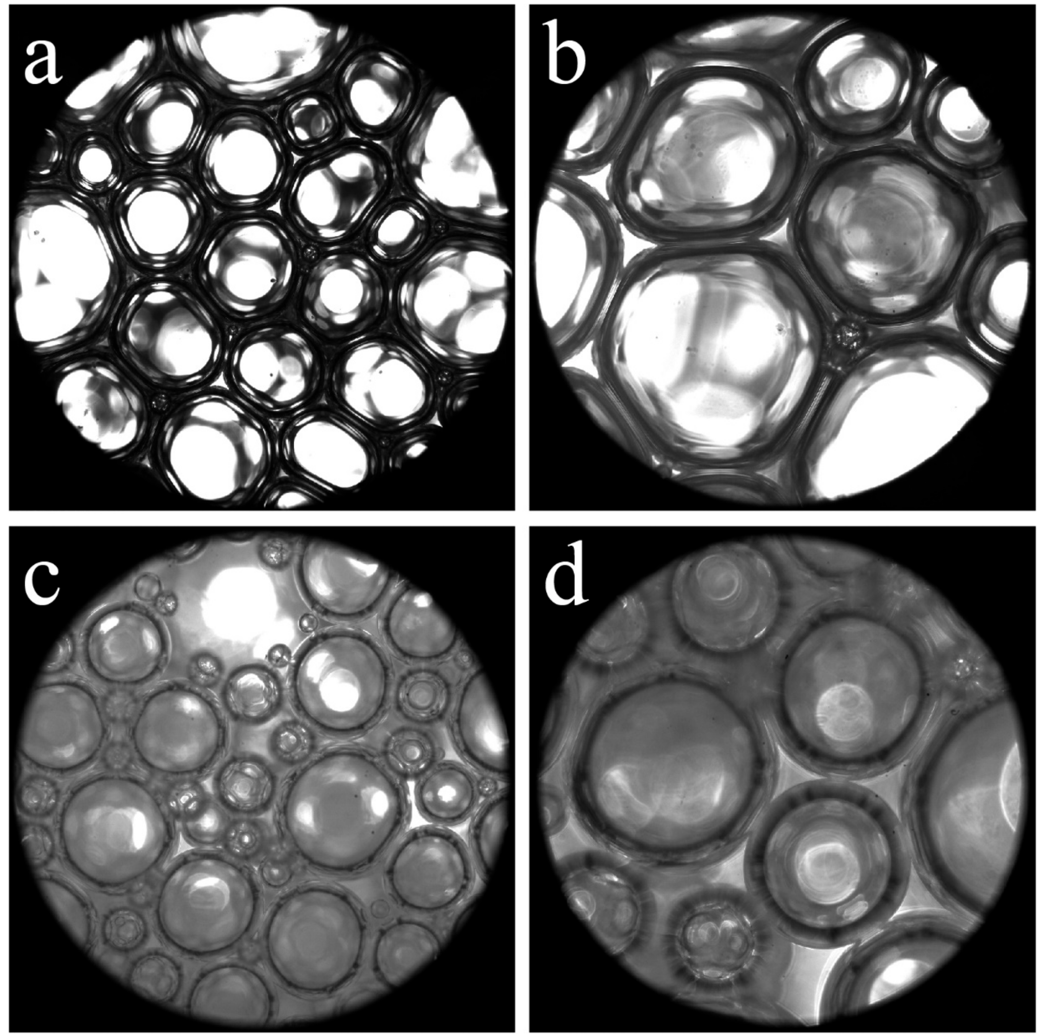
Foam Microstructure
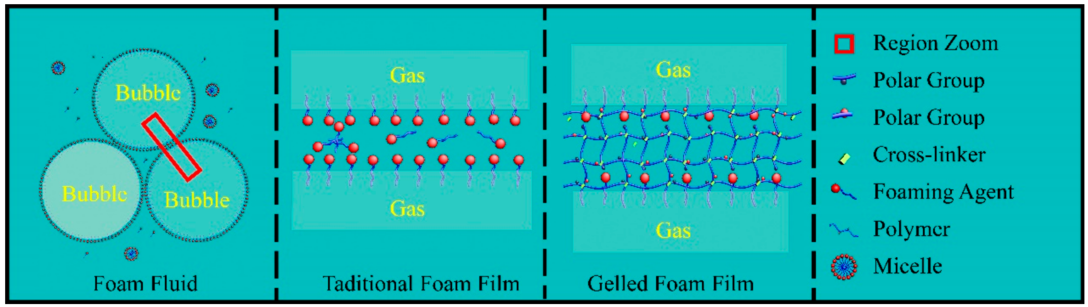
Foam Stabilization Mechanism
3.2. Formation Adaptability
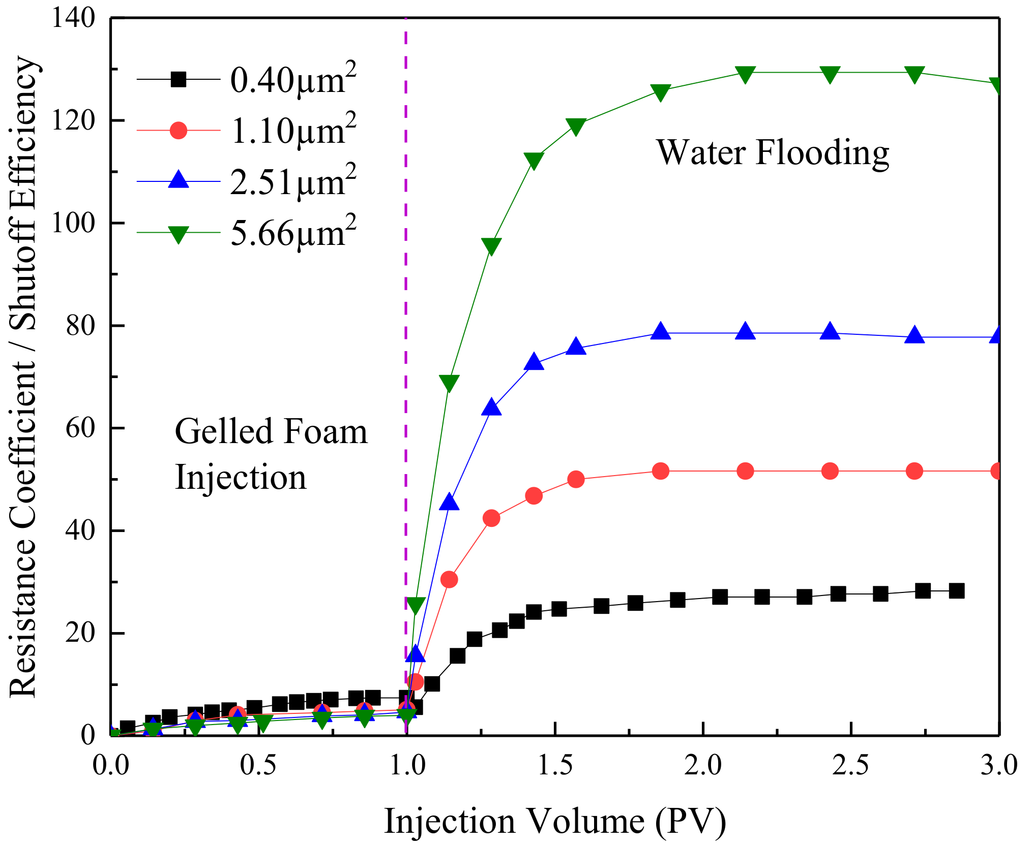
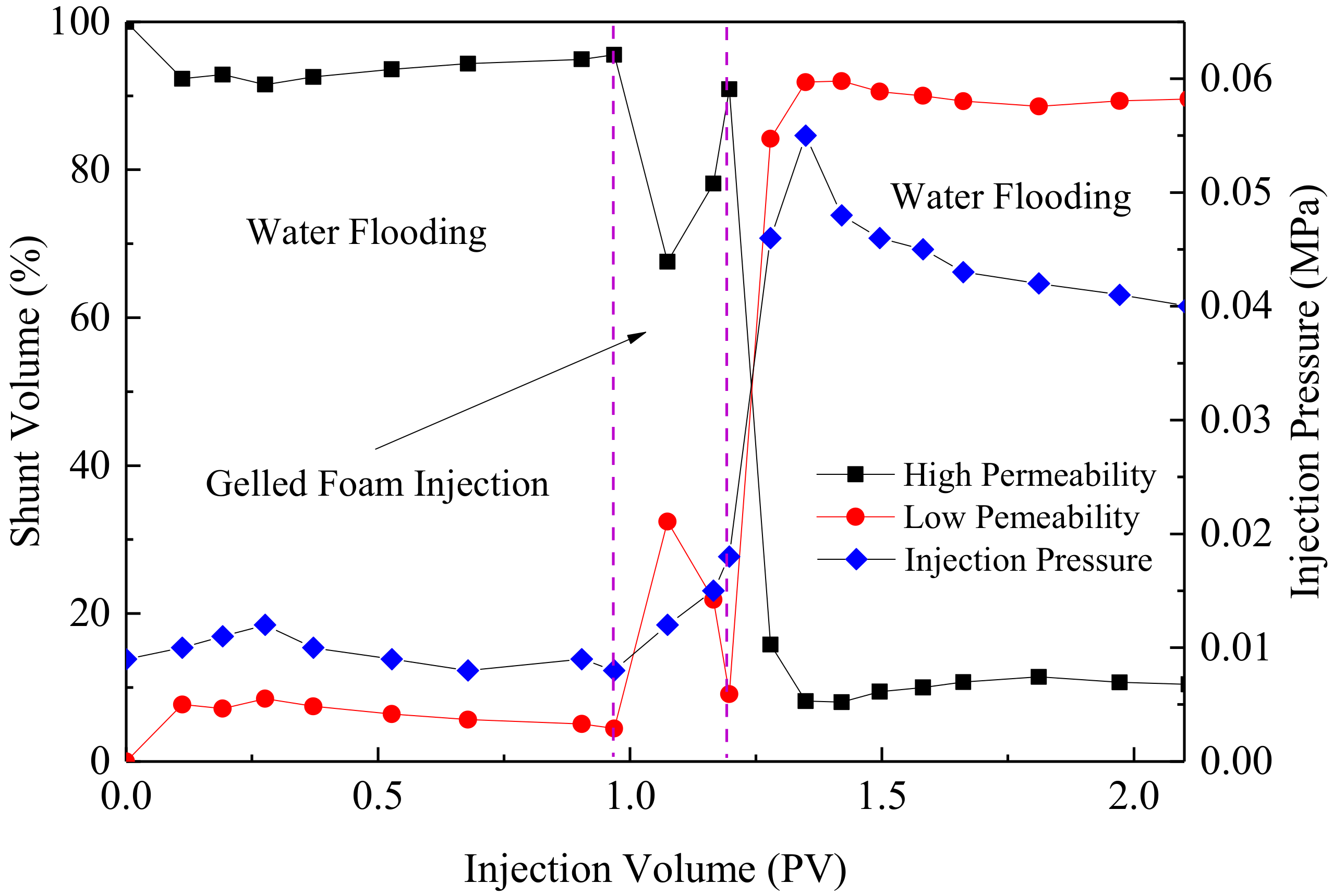
3.3. Profile Control Performance
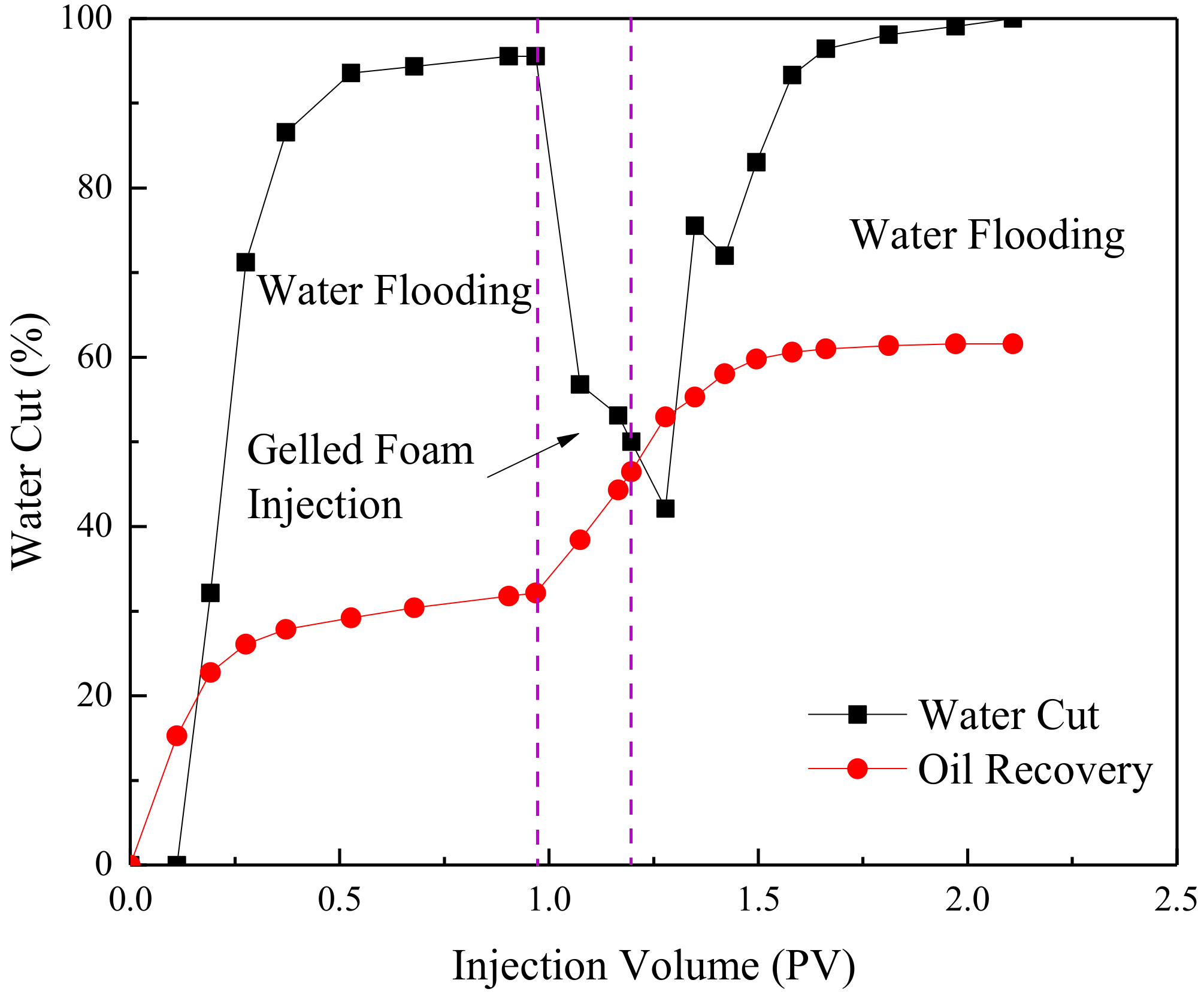
3.4. EOR Performance
4. Conclusions
Author Contributions
Acknowledgments
Conflicts of Interest
References
- Coll, C.; Muggeridge, A.H.; Jing, X. Regional upscaling: A new method to upscale waterflooding in heterogeneous reservoirs for a range of capillary and gravity effects. SPE J. 2001, 6, 299–310. [Google Scholar] [CrossRef]
- Loahardjo, N.; Xie, X.; Morrow, N.R. Oil recovery by sequential waterflooding of mixed-wet sandstone and limestone. Energy Fuels 2010, 24, 5073–5080. [Google Scholar] [CrossRef]
- Xiao, B.; Zhang, X.; Wang, W.; Long, G.; Chen, H.; Kang, H.; Ren, W. A Fractal model for water flow through unsaturaturated porous rocks. Fractals 2018, 26, 1840015. [Google Scholar] [CrossRef]
- Long, G.; Xu, G. The effects of perforation erosion on practical hydraulic-fracturing applications. SPE J. 2017, 22, 645–659. [Google Scholar] [CrossRef]
- Brouwer, D.R.; Jansen, J.D. Dynamic optimization of waterflooding with smart wells using optimal control theory. SPE J. 2004, 9, 391–402. [Google Scholar] [CrossRef]
- Han, D. An approach to deep development of high water-cut oil fields to improve oil recovery. Petrol. Exp. Dev. 1995, 22, 47–55. [Google Scholar]
- Chunming, X.; Xiaofen, T. Technologies of water shut-off and profile control: An overview. Petrol. Exp. Dev. 2007, 34, 83–88. [Google Scholar]
- Zongying, Z.; Kang, Z. Development situation and prospect of oil fields in China. Petrol. Exp. Dev. 2004, 31, 84–87. [Google Scholar]
- You, Q.; Yu, H.; Wang, Y.; Zhang, J.; Yang, G.; Zhao, W.; Zhao, F. Technologies of in-depth profile control in China. Fault-Block Oil Gas Field 2009, 16, 68–71. [Google Scholar]
- Yao, C.; Lei, G.; Lei, L.; Gao, X. Selectivity of pore-scale elastic microspheres as a novel profile control and oil displacement agent. Energy Fuels 2012, 26, 5092–5101. [Google Scholar] [CrossRef]
- Yao, C.; Lei, G.; Hou, J.; Xu, X.; Wang, D.; Steenhuis, T.S. Enhanced oil recovery using micron-size polyacrylamide elastic microspheres: Underlying mechanisms and displacement experiments. Ind. Eng. Chem. Res. 2015, 54, 1520–5045. [Google Scholar] [CrossRef]
- Bai, B. Preformed particle gel for conformance control: Factors affecting its properties and applications. SPE Reserv. Eval. Eng. 2007, 10, 415–422. [Google Scholar] [CrossRef]
- Bai, B.; Zhou, J.; Yin, M. A comprehensive review of polyacrylamide polymer gels for conformance control. Petrol. Exp. Dev. 2015, 42, 525–532. [Google Scholar] [CrossRef]
- Bai, B.; Huang, F.; Liu, Y.; Seright, R.S.; Wang, Y. Case study on prefromed particle gel for in-depth fluid diversion. In Proceedings of the SPE Symposium on Improved Oil Recovery, Tulsa, OK, USA, 20–23 April 2008. [Google Scholar]
- Jichao, F.; Jianhai, W.; Quanyi, W.; Sisi, F.; Xiaoqing, H.; Yan, M. Research of phenolic crosslinker gel for profile control and oil displacement in high temperature and high salinity reservoirs. J. Appl. Polym. Sci. 2018, 135, 46075. [Google Scholar]
- Jia, H.; Pu, W.F.; Zhao, J.Z.; Liao, R. Experimental investigation of the novel phenol−formaldehyde cross-linking hpam gel system: Based on the secondary cross-linking method of organic cross-linkers and its gelation performance study after flowing through porous media. Energy Fuels 2011, 25, 727–736. [Google Scholar] [CrossRef]
- Puerto, M.; Hirasaki, G.J.; Miller, C.A.; Barnes, J.R. Surfactant systems for EOR in high-temperature, high-salinity environments. SPE J. 2010, 17, 11–19. [Google Scholar] [CrossRef]
- Xiao, B.; Wang, W.; Fan, J.; Chen, H.; Zhao, D.; Zhang, X.; Ren, W. Optimization of the fractal-like architecture of porous fibrous materials related to permeability, diffusivity and thermal conductivity. Fractals 2017, 25, 1750030. [Google Scholar] [CrossRef]
- Kovscek, A.R.; Bertin, H.J. Foam mobility in heterogeneous porous media. Transp. Porous Media 2003, 52, 17–35. [Google Scholar] [CrossRef]
- Xiao, B.; Chen, H.; Xiao, S.; Cai, J. Research on relative permeability of nanofibers with capillary pressure effect by means of fractal-monte carlo technique. J. Nanosci. Nanotechnol. 2017, 17, 6811–6817. [Google Scholar] [CrossRef]
- Li, R.F.; Yan, W.; Liu, S.; Hirasaki, G.; Miller, C. Foam mobility control for surfactant enhanced oil recovery. SPE J. 2010, 15, 928–942. [Google Scholar] [CrossRef]
- Shan, D.; Rossen, W.R. Optimal Injection Strategies for Foam IOR. SPE J. 2004, 9, 75180. [Google Scholar] [CrossRef]
- Dai, C.; Zhao, J.; Yan, L.; Zhao, M. Adsorption behavior of cocamidopropyl betaine under conditions of high temperature and high salinity. J. Appl. Polym. Sci. 2014, 131, 383–390. [Google Scholar] [CrossRef]
- Ji, Z.; Jichao, F.; Daiyu, Z.; Jianhui, Z.; Shiti, C.; Caili, D. Surfactant Flooding in Tazhong 402CIII High-Temperature and High-Salinity Reservoir. Oilfield Chem. 2014, 31, 405–409. [Google Scholar]
- Jichao, F.; Caili, D.; Qing, Y. Study on foam flooding in high-temperature and high-salinity reservoir of Tazhong 402CIII. Petrol. Geol. Recovery Effic. 2014, 21, 84–88. [Google Scholar]
- Zhao, F. Principle of EOR; China University of Petroleum Press: Dongying, China, 2016; Chapter 6; p. 118. [Google Scholar]
- Wang, P. Overview on technology of water shut off/profile control agent of foam. Drill. Prod. Technol. 2000, 23, 60–61. [Google Scholar]
- Zhao, G.; Dai, C.; Zhang, Y.; Chen, A.; Yan, Z.; Zhao, M. Enhanced foam stability by adding comb polymer gel for in-depth profile control in high temperature reservoirs. Colloids Surf. A Physicochem. Eng. Asp. 2015, 482, 115–124. [Google Scholar] [CrossRef]
- Dai, C.; Feng, H.; Jian, J.; Zhao, M.; He, X.; Zhao, J. A selective water-plugging system with heat-resistant gelled foam: A case study from the East China sea gas field. Nat. Gas Ind. 2015, 35, 60–67. [Google Scholar]
- Huh, C.; Rossen, W.R. Approximate pore-level modeling for apparent viscosity of polymer-enhanced foam in porous media. SPE J. 2008, 13, 17–25. [Google Scholar] [CrossRef]
- Telmadarreie, A.; Trivedi, J.J. New insight on carbonate heavy oil recovery: Pore scale mechanisms of solvent alternating CO2 foam/polymer enhanced foam flooding. In Proceedings of the SPE Canada Heavy Oil Technical Conference, Calgary, AB, Canada, 9–11 June 2015. [Google Scholar]
- Nguyen, P.; Fadaei, H.; Sinton, D. Pore-scale assessment of nanoparticle-stabilized CO2 foam for enhanced oil recovery. Energy Fuels 2014, 28, 6221–6227. [Google Scholar] [CrossRef]
- Guo, F.; Aryana, S. An experimental investigation of nanoparticle-stabilized co2 foam used in enhanced oil recovery. Fuel 2016, 186, 430–442. [Google Scholar] [CrossRef]
- San, J.; Wang, S.; Yu, J.; Liu, N.; Lee, R. Nanoparticle-stabilized carbon dioxide foam used in enhanced oil recovery: Effect of different ions and temperatures. SPE J. 2017, 22, 179628. [Google Scholar] [CrossRef]
- Rognmo, A.U.; Heldal, S.; Fernø, M.A. Silica nanoparticles to stabilize CO2-foam for improved CO2 utilization: Enhanced CO2 storage and oil recovery from mature oil reservoirs. Fuel 2018, 216, 621–626. [Google Scholar] [CrossRef]
- Wassmuth, F.R.; Hodgins, L.H.; Schramm, L.L.; Kutay, S.M. Screening and coreflood testing of gel foams to control excessive gas production in oil wells. In Proceedings of the SPE/DOE Improved Oil Recovery Symposium, Tulsa, OK, USA, 3–5 April 2000. [Google Scholar]
- Wassmuth, F.R.; Hodgins, L.A.; Schramm, L.L.; Kutay, S.M. Screening and coreflood testing of gel foams to control excessive gas production in oil wells. SPE Reserv. Eval. Eng. 2001, 4, 72096. [Google Scholar] [CrossRef]
- Asghari, K.; Taabbodi, L.; Dong, M. A new gel-foam system for water shut-off purposes in wormhole reservoirs. In Proceedings of the SPE International Thermal Operations and Heavy Oil Symposium, Calgary, AB, Canada, 1–3 November 2005. [Google Scholar]
- Wang, X.; Dong, M.; Zhou, W. Polymer/gel enhanced foam flood for improving post-waterflood heavy oil recovery. In Proceedings of the SPE Heavy Oil Conference-Canada, Calgary, AB, Canada, 11–13 June 2013. [Google Scholar]
- Friedmann, F.; Hughes, T.L.; Smith, M.E.; Hild, G.P.; Wilson, A.; Davies, S.N. Development and testing of a foam-gel technology to improve conformance of the Rangely CO2 flood. SPE Reserv. Eval. Eng. 1999, 2, 54429. [Google Scholar] [CrossRef]
- Hughes, T.L.; Friedmann, F.; Johnson, D.; Hild, G.P.; Wilson, A.; Davies, S.N. Large-volume foam-gel treatments to improve conformance of the Rangely CO2 Flood. SPE Reserv. Eval. Eng. 1999, 2, 54772. [Google Scholar] [CrossRef]
- Zhang, Y.; Dai, C.; Xu, X.; Wang, S.; Yan, L.; Xin, C. Research and application on nitrogen foam flooding in Henan Oilfield. Fault-Block Oil Gas Field 2013, 20, 129–132. [Google Scholar]
- Li, B. Study on Profile Control and Flooding Technology of Nitrogen Foam and Its Applicability; China University of Petroleum Press: Dongying, China, 2007. [Google Scholar]
- Sydansk, R.D. Delayed In-situ Crosslinking of Acrylamide Polymer for Oil Recovery Application in High Temperature Formation. U.S. Patent 4,844,168, 4 July 1989. [Google Scholar]
- Zhao, F.L. Oilfield Chemistry; China Petroleum University Press: Dongying, China, 2001; pp. 95–96. [Google Scholar]
- Guo, Z.; Xu, C.; Lu, Y. Foamability and stability of foam and means of evaluating. Chem. Eng. 2006, 4, 51–54. [Google Scholar]
- Wang, L.; Yu, T.; Cao, Q.; Cao, Y.; Meng, Q. Interfacial Viscoelasticity and Performance Properties of BS-12 Foam for EOR. Oilfield Chem. 2007, 24, 70–74. [Google Scholar]
- Xie, J.; Fan, S. On Foam Stability. Oildfield Chem. 1988, 5, 56–63. [Google Scholar]
- Fang, J.; Zhang, X.; He, L.; Zhao, G.; Dai, C. Experimental research of hydroquinone (HQ)/hexamethylene tetramine (HMTA) gel for water plugging treatments in high-temperature and high-salinity reservoirs. J. Appl. Polym. Sci. 2017, 134, 44359. [Google Scholar] [CrossRef]
- Wang, J.; Wang, S.; Zhao, S. Study on profile control and oil displacement system for gelled foam of high-temperature reservoir in Zhao’ao oilfield. Petrol. Geol. Recovery Effic. 2013, 20, 57–61. [Google Scholar]
- You, Q.; Wang, H.; Zhang, Y.; Liu, Y.; Fang, J.; Dai, C. Experimental study on spontaneous imbibition of recycled fracturing flow-back fluid to enhance oil recovery in low permeability sandstone reservoirs. J. Petrol. Sci. Eng. 2018, 166, 375–380. [Google Scholar] [CrossRef]
- Liu, S.; Wang, J.; He, H.; Wang, H. Mechanism on Imbibition of Fracturing Fluid in Nanopore. Nanosci. Nanotechnol. Lett. 2018, 10, 87–93. [Google Scholar] [CrossRef]


| Ion Composition | Ca2+ | Mg2+ | Cl− | Na+ | Salinity |
|---|---|---|---|---|---|
| Concentration (mg/L) | 9000 | 240 | 142,000 | 70,380 | 221,620 |
| Physics Model | Length/cm | Diameter/cm | Permeability/µm2 | Pore Volume/mL | |
|---|---|---|---|---|---|
| One sand pack | No.1 | 20 | 2.5 | 0.40 | 34 |
| No.2 | 20 | 2.5 | 1.10 | 35 | |
| No.3 | 20 | 2.5 | 2.51 | 36 | |
| No.4 | 20 | 2.5 | 5.66 | 37 | |
| Two sand packs | High permeability | 20 | 2.5 | 2.53 | 36 |
| Low permeability | 20 | 2.5 | 0.48 | 34 | |
| 0.4% HPAM + 0.06% Phenolic Cross-Linker (100 °C) | ||||
|---|---|---|---|---|
| Aging Time (days) | 5 | 10 | 30 | 60 |
| Dehydration amount (%) | 0 | 1.2 | 1.5 | 1.5 |
© 2018 by the authors. Licensee MDPI, Basel, Switzerland. This article is an open access article distributed under the terms and conditions of the Creative Commons Attribution (CC BY) license (http://creativecommons.org/licenses/by/4.0/).
Share and Cite
Li, T.; Fang, J.; Jiao, B.; He, L.; Dai, C.; You, Q. Study on a Novel Gelled Foam for Conformance Control in High Temperature and High Salinity Reservoirs. Energies 2018, 11, 1364. https://doi.org/10.3390/en11061364
Li T, Fang J, Jiao B, He L, Dai C, You Q. Study on a Novel Gelled Foam for Conformance Control in High Temperature and High Salinity Reservoirs. Energies. 2018; 11(6):1364. https://doi.org/10.3390/en11061364
Chicago/Turabian StyleLi, Tong, Jichao Fang, Baolei Jiao, Long He, Caili Dai, and Qing You. 2018. "Study on a Novel Gelled Foam for Conformance Control in High Temperature and High Salinity Reservoirs" Energies 11, no. 6: 1364. https://doi.org/10.3390/en11061364
APA StyleLi, T., Fang, J., Jiao, B., He, L., Dai, C., & You, Q. (2018). Study on a Novel Gelled Foam for Conformance Control in High Temperature and High Salinity Reservoirs. Energies, 11(6), 1364. https://doi.org/10.3390/en11061364