1. Introduction
Storage of renewable energies from fluctuating sources needs storage technologies with quite different characteristics. The backup for highly transient load changes and longer periods without wind and solar power requires mainly back-up sources with high capacities in terms of power (kilowatt) and stored energy (kilowatt hours). These backup capacities are likely to provide only few hours of operation throughout the year. High storage efficiency is therefore not a predominant feature of these systems and a combination of chemical storage with the existing natural gas infrastructure is most likely appropriate to serve these storage tasks in the short and medium term.
More challenging in terms of efficiency and CO
2 savings is the task that requires the storage of solar power from noon peaks in order to shift this energy to evening and night periods. Such storage systems have to operate on a daily basis nearly continuously with a high number of operational hours. Economics of such “base load” storage systems are therefore less sensitive to high investments but they require highest efficiencies in order to minimize operational costs. The main operational costs are in this case the costs for electricity during daytime. These costs are rarely negative and determine the final costs of the power provided by the storage system. However, these costs will certainly increase due to reduced capacities of nuclear and conventional power plants [
1].
The most suitable state-of-the-art technologies for an efficient storage of electricity are batteries, pumped hydro storage and compressed air storage systems. These technologies allow efficiencies of significantly above 50% and enjoy a high maturity level. However, these technologies suffer of different constrains: Pumped hydro storages and underground compressed air storage systems are depending on geographical conditions [
2] and batteries are characterized by their low cycle life, limited raw materials resources and still high costs [
3]. Due to that, new and economically more competitive concepts for an efficient storage of energy are needed [
4].
Both, heat pump and Organic Rankine Systems are historically closely connected to the use or upgrading of geothermal energy [
5]. Deep geothermal heat was used for power production in Organic Rankine Cycles [
6] and heat pumps upgrade near-surface geothermal energy for heating purposes. Other authors considered the application of ORC processes for the use and storage of solar thermal energy [
7,
8], or desalination [
9]. Systems for the use of solar energy are no longer competitive to photovoltaic systems due to the need for a costly cooling system and the increased efficiencies and reduced costs of PV panels [
10]. Due to a lack of combined heat and power production (CHP) technologies the small-scale Organic Rankine plants became quite popular for biomass CHP plants [
11,
12,
13,
14] and for bottoming cycle for gas engines [
15]. Using ORC’s as bottoming cycle for gas engine became particularly attractive for the use of waste heat in biogas plants [
16].
The thermodynamic optimization of the ORC systems targets mainly three topics: the selection of appropriate working fluids, the selection of an appropriate working expander technology and the system integration [
17]. The selection of the working fluid bases mainly on its environmental properties: zero Ozone Depletion Potential (ODP) and ultra-low Global warming potential (GWP) (<10), respecting the F-gas Regulation [
18], non-toxic and non-flammable. Recently, new hydrofluoroolefins (HFOs) have been developed and can be used to replace hydrofluorocarbons (HFCs), meeting all previous specs, and thus ensuring its sustainability. This so called “screening method” isn’t limited to pure fluids. Also mixtures of two or more fluids can be considered [
19]. In recent years research on the selection of the expander became more important. The expander determines the pressure ratio in evaporator and condenser and therefore the temperature spread of the process for a given working fluid. This determines the evaporation and condensation of the fluid and in particular the pinch points and efficiency of the heat exchangers [
20]. A similar impact has the system integration of the ORC. Especially the adaptation of the evaporation to the temperature levels of the heat source determines the system efficiency [
21]. Here, several authors propose the use of binary mixtures and zeotropic working fluids [
11,
22,
23] or the application of supercritical fluids [
24].
The selection of the working fluid for heat pump systems focuses mainly on the fluids global warming potential, the applicable temperature levels [
25] and the integration with storage systems [
26,
27]. Again, recent investigations focus mainly on the use of geothermal [
28] or solar heat [
29]. A recent patent application comprises the storage of excess electricity with heat pumps in heat storage systems for later use in heating grids [
30].
The idea to use the heat pump also in Organic Rankine Cycle mode was proposed by Dumont [
31] and Schimpf [
32]. Dumont [
33] focused mainly on the applicability to use a scroll alternating as compressor and expander whereas Schimpf performed system simulations based on the integration of solar energy. An advancement of Dumonts set-up concerns the use of a single volumetric machine to reduce the complexity and equipment cost. Steinmann [
34] proposed a similar system based on steam cycles and latent heat storage in NaNO
3 and KNO
3. A trigeneration system for an optimized use of renewable energy (e.g., solar or biomass) based on an ORC and a heat pump with a separate expander and compressor [
35] has been tested and validated at the NTUA labs in Athens.
2. Technical Concept
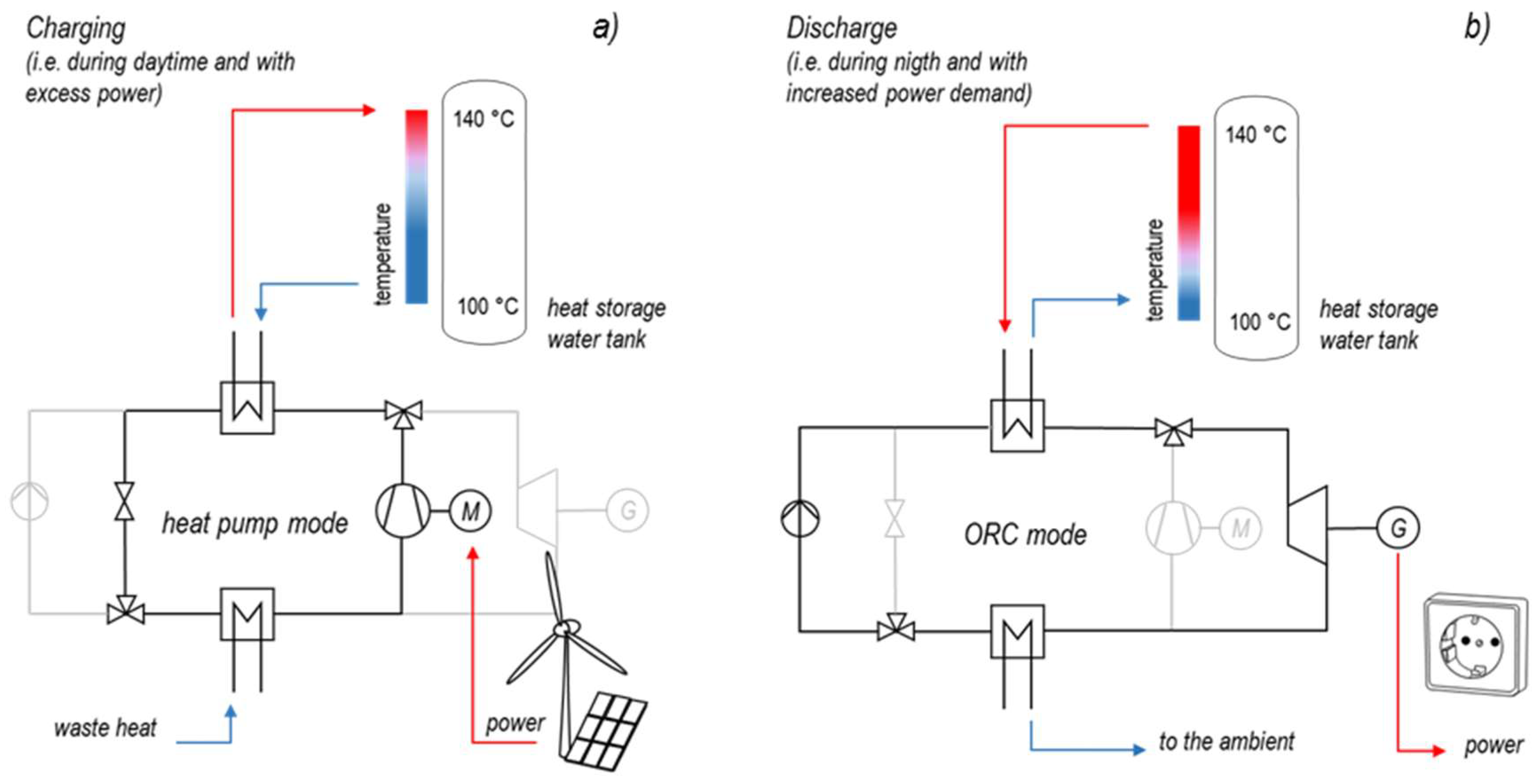
The novel system outlined in
Figure 1 comprises the combination of a heat pump (HP) and an Organic Rankine Cycle (ORC) with a simple hot water storage tank. Systems with thermal heat storage at moderate temperatures provide usually extremely low efficiencies due to the high exergetic losses of a heat engine operating at low temperatures. Storing electricity in hot water loses most of its exergy even at high water temperatures and pressures as shown for the upper reference set-up in
Figure 1. Thus, recovering of the electricity from hot water by means of an Organic Rankine Cycle will only recover a very small part of the electricity input. The same accounts for the conversion of low-temperature waste heat sources such as geothermal heat or unused process heat for electricity production. The system becomes more efficient if the electricity provides only a minor part of the stored heat. Upgrading the temperature of the waste heat by means of excess electricity makes the use of an ORC feasible in order to recover the electricity input more efficiently.
In case that the volatile electricity
is used to upgrade waste heat
–for example from geothermal plants, computing centers or industrial processes—the power-to-power efficiency becomes more favorable because part of the produced electricity
comes finally from the low-cost waste heat source. The total process efficiency:
is still low but the commonly applied definition of the power-to-power efficiency
:
improves significantly in case that the water tank stores not only energy from excess power. More competitive efficiencies are achievable if the excess power is used to operate a heat pump which upgrades a certain amount of heat
to the heat storage system. The power-to-power efficiency depends directly on the Rankine cycles thermal efficiency
and the heat pumps Coefficient-Of-Performance
:
Equation (3) neglects losses from the thermal storage system. These losses depend mainly on the duration between charging of the system in heat pump mode and discharging in ORC mode. In case that the system serves for short-term storage—for instance with charging and discharging on a daily basis—the heat losses to the environment are small in comparison to the storage tanks total heat content. More significant exergy losses appear due to internal mixing and a loss of the thermal stratification [
36] and depend mainly on the design of the storage system [
37].
3. Thermodynamic Considerations
High COPs require high temperature levels for the waste heat source and low storage temperatures for the thermal storage systems. The ORC requires high temperatures for the thermal heat storage on the other hand. This leads to an optimization problem in order to determine the most favorable water storage temperatures for available working fluids.
In case that the exergy of the waste heat adds to the exergy of the stored electricity, the total energy and exergy in the hot water storage increases even if the same temperatures apply. The additional exergy compensates the exergy losses of heat pump and ORC and provides significantly higher power-to-power efficiencies as shown in
Figure 1. The power-to-power efficiencies maximize in case that the volatile power input becomes negligible in comparison to the waste heat supply. However, feasible ratios between power and waste heat input are still able to provide power-to-power efficiencies above 70% as shown in
Figure 2.
The limitation for the power-to-power efficiency comes from the Carnot efficiencies of the heat pump and the ORC process, taking into account an efficiency factor g for both the heat pump:
and the Organic Rankine Cycle:
The efficiency factor
g equals the exergetic efficiency and describes the ratio between the efficiency of real processes of the ideal Carnot efficiency. It ranges usually between 50 and 70% depending on the size of the plant and its complexity.
Figure 2 shows the severe impact of the efficiency factor on the power-to-power efficiency for the given setup. A temperature level of the waste heat source of 80 °C and an ambient temperature of 40 °C provides power-to-power efficiencies above 50% in particular for storage temperatures below 150 °C.
Figure 2 indicates that the system might also provide power-to-power efficiencies above 100%. This denotes of course not the total efficiency defined in Equation (1) and does not contradict the first law of energy conservation. The power-to-power efficiency results from the definition Equation (2) which simply neglects the energy coming from the waste heat source.
The ideal system layout would focus on storage temperatures close to the temperature of the waste heat source (here: below 100 °C). However, this increases the required storage volume inadequately. An economic optimization will naturally lead to significantly higher storage temperatures.
4. System Setup
The main advantage of the proposed concept is that the process requires just one single apparatus. Most components of a heat pump can serve as components for an Organic Rankine Cycle. In particular the costly heat exchangers can comprise both, the condenser and the evaporator in the heat pump as well as in ORC mode. Even the compressor of the heat pump can be used as expander of the Rankine cycle. Only the throttle valve of the heat pump has to be replaced with a pump as shown in
Figure 3.
The development and demonstration of such a reversible heat pump–organic Rankine engine and its combination with heat storage at temperatures up to 180 °C is the main objective of an ongoing joint research project at the Energy Campus Nuremberg.
The process efficiency depends mainly on the isentropic efficiencies of compressor and expander as explained later. Another focus especially for small-scale applications lays on the selection of the working principle of the compressor/expander as it is desired to use the same machine in both processes. In general, there is a number of designs possible, which allow a reversible operation: Dumont et al. [
27] investigated a small-scale scroll unit used as compressor and as expander. In a similar way, it is technically possible to apply a commercial available screw compressor as an expander. Besides these, the working principles of sliding vane compressors and piston compressors are theoretically applicable for the use as expanders but show the difficulties of the small-scale or the complexity of valve control. Of course, the efficiency of the machine has a huge impact on the overall-efficiency.
Table 1 shows a comparison of four volumetric expanders evaluated in several features.
Additional to the criteria of expander selection in the table, reversible operation of a machine brings further big challenges:
These can be faced with an optimization of the process design, which enables a similar pressure ratio in both compression and expansion. To ensure sufficient lubrication in both modes, established concepts should be reconsidered. Of course, the efficiency losses must be minimized to ensure an economical reasonable reversible operation at all. Another challenge is the outlet temperature of the compressor, which can–depending on the temperature level of the energy storage–reach up to 200 °C. This requires additional consideration about thermal expansion, material resistance and lubricant behavior. However, using the same machine as compressor and expander defines both, the pressure ratios in heat pump and ORC mode. This usually prevents the plants operation in thermodynamic optimum for the selected working fluid. Furthermore, the isentropic efficiency volumetric expanders is limited to approximately 60% resulting in power-to-power efficiencies below 50% as shown later on. Technical applications of this approach are therefore only feasible for small-scale applications when specific investments dominate the economic performance of the cycle. Larger scale applications on the other hand will allow the use of tailor made turbines and compressors in order to operate the cycles at the thermodynamic optimum and with higher isentropic efficiencies. The thermodynamic optimum depends on the working fluid as shown later.
Charging and discharge of the hot water heat storage can easily use the thermal stratification of a quite simple water tank. A special meaning in terms of storage size and investment costs comes to the temperature spread in the vessel. Small spreading increases the tanks volume and investment cost. Temperatures above 100 °C may require naturally pressurized storage vessels with increased investments. The low energy density of sensible heat storage leads to extraordinary large volumes.
The thermal storage volume of a sensible heat storage tank depends on the storage volume, the heat capacity of the storage material and the temperature lift. Sensible heat storage provides two significant advantages in contrast to other heat storage technologies such as latent heat storage with phase change materials (PCM) or chemical storage technologies. The first main advantage is the availability and costs of the storage materials such as water or solids. A second significant advantage are sliding temperatures that can adjust to the available temperatures during charging and discharging as shown in the thermodynamic analysis (chapter System Optimization). The potential of a sensible heat storage material originates from its volumetric energy density per Kelvin
[J m
−3 K
−1]. Storage with high energy density consumes considerably less space and reduces investment costs accordingly. The mass of the storage is usually less important and only influences the fundament of the building. Equation (6) defines the thermal energy stored with the temperature spread ∆T within the storage volume
VS. The density
ρSM and the isobar heat capacity
cp of the storage material provide the volumetric heat capacity
CSM:
A commonly used storage medium is water, which offers a high volumetric heat capacity (4170 kJ m−3 K−1 at standard conditions). Temperatures above 100 °C require pressurized tanks.
Alternatively, solid storage mediums, which do not need to be pressurized, in combination with thermal oils can be considered. Iron offers an energy density comparable to water (3535 kJ m−3 K−1 at 298.15 K standard conditions). In this case, the heat transfer is complex and the thermal conductivity of the material has to be considered.
The storage system for the described process is designed for daily use. The ORC’s power capacity and a desired operation of 2–8 full load hours during nighttime defines its dimensioning.
The electrical storage volume is defined by the efficiency of the ORC. The round trip efficiency depends on the power-to-power efficiency of the whole system. Furthermore, the heat loss and the efficiency of the heat recovery of the storage have to be taken into account.
A specific storage volume:
which defines the storage volume per nominal power of the ORC process depends solely on the discharge duration
t, the volumetric heat capacity
CSM, the temperature spread ∆
T and the ORC’s electrical efficiency
.
As presented in
Figure 4 the electrical storage capacity grows not only with rising temperature spread. Another important parameter is the storage temperature itself. High storage temperatures increase the Carnot efficiency of the ORC process and reduce the required storage volume accordingly. The COP of the heat pump on the other hand drops with higher target temperatures. Therefore, an optimum for the power-to-power and the storage capacity, will base on investment cost and plant economics.
5. System Optimization
Figure 2 demonstrates the huge impact of the efficiency factors
gHP and
gORC on the total process efficiency. These efficiency factors describe the exergy losses of the processes.
The first main sources for these losses are the isentropic losses of the heat pump’s compressor and the expander/turbine of the Rankine cycle. Standard components of heat pumps such as scroll expanders and screw compressors provide isentropic efficiencies between 60 and 70%.
The exergy losses are in this case between 30 and 40% during both, charging and discharge of the system. Scroll expanders and similar technologies are therefore not an ideal choice for the system in spite of the comparably low invest costs.
The second main source for exergy losses are the heat exchangers. The need for high efficiencies justifies generally large heat exchangers with small terminal temperature differences at the pinch points. But an additional limitation comes from working fluids properties in combination with the expanders/compressors pressure ratio. Definition of the upper and lower temperature levels of the water storage determines the temperatures during the heating and cooling of the working fluid in case that the heat exchanger specifications are given. The pinch points in the heat pump’s condenser and the Rankine cycle’s evaporator determine the pressure during condensation and evaporation as shown in
Figure 5. The condensation temperature in the heat pump’s condenser has to be significantly above the maximum heat storage temperature and the Rankine cycle’s evaporation temperature lies several degrees below the hot water inlet. The heat pump’s condenser pressure increases therefore and the COP reduces while the upper pressure level and the efficiency of the ORC decrease. The different temperature and pressure levels in heat pump and ORC become also obvious with the t, s diagram of the processes as shown in
Figure 6.
Different pressure levels do not necessarily mean different pressure ratios in heat pump and ORC mode. The different temperatures of the waste heat source, the ambient and the choice of the working fluid provide additional degrees of freedom. The heat pump’s compressor can still serve as expander as earlier mentioned. But the efficiency factor might reduce and the optimization of the process parameters and the choice of an appropriate working fluid becomes most significant.
Other options for the system’s optimization are advanced process setups.
Figure 7 shows three main principles that increase the cycle efficiency. These principles apply to both the heat pump mode and to the operation of the system in ORC mode. The first two principles–the recuperation of the condenser’s/turbine’s drain heat (
Figure 7a,d) as well as the condensate split and feed reheat (
Figure 7b,e) aim at an increased temperature of the compressor feed in heat pump mode and an increased evaporator feed in ORC mode. The use of a recuperator (
Figure 7a,d) is the most common measure for small-scale heat pump and ORC processes. The feed (water) reheat (
Figure 7e) [
39] is the most effective process improvement in particular for larger scale steam cycles. The corresponding condensate split is less common for heat pumps (
Figure 7b).
However, both principles increase the cycle efficiency but increase simultaneously the exergy losses of the heat transfer in condenser and evaporator. The heat pump process would commonly benefit from high condenser drain temperatures, which allow for an ideal preheat of the compressor feed. But an unfavorable pinch point might require an unnecessary high superheating of the working fluid which reduces the COP as shown in
Figure 5a.
The same problem applies for the single stage Rankine cycle. Commonly preferred high feed temperatures at the inlet of the evaporator might lead to an unfavorable position of the evaporators pinch point, which reduces the evaporation pressure and the cycle’s thermal efficiency (
Figure 5b).
Both problems depend mainly on the temperature spread of the hot water in the storage vessel and vanish in case that the temperature spread reduces to a few degrees. However, this increases size and costs of the storage tank and will not necessarily improve the complete processes power-to-power efficiency as shown later. So the main principle to reduce efficiency losses of the heat exchangers with higher temperature spreads are therefore staged condensation and evaporation as depicted in
Figure 7c,f. The principle minimizes temperature gradients in the heat exchangers and reduces the heat transfers exergy losses most effectively.
An optimized process might of course combine these three principles. This leaves a vast amount of opportunities for system optimization.
Figure 6 illustrates the different temperature and pressure levels of heat pump and Rankine cycle in a t, s diagram. Furthermore, the Pinch Point limitations of condensation und evaporation temperatures become obvious. The different entropy scales for the hot water lines result from the different mass flows of the ORC/heat pump cycle in case that the same amount of heat is transferred from/to the hot water cycle. A decrease of the condensation pressure in the heat pump leads to a higher superheating of the compressed working fluid.
This results automatically in higher entropies at the heat exchangers inlet and outlet, which indicates a lower efficiency of the heat transfer. A similar effect appears for the evaporation in the ORC. A higher feed temperature reduces the evaporation pressure and rises the superheating. This also causes higher entropies during the heat exchange.
6. Simulation and Parameter Optimization
The process was finally analyzed by means of the software system IPSEpro (Version 7.0, SimTech GmbH, Graz, Austria). This software package enables the calculation of heat balances and cycle simulation of processes. Two different models have been implemented. The first one is the combination of a single stage heat pump and Rankine processes with recuperator as shown in
Figure 7a,d.
Figure 8 depicts the resulting IPSEpro model.
The two staged setup shown in
Figure 9 applies the staged condensation and evaporation as previously discussed in
Figure 7c,f. The fixed variables for both setups are the same as shown in
Table 2. The working fluid R365mfc has already been used for high temperature heat pump applications [
25,
40] as well as in ORCs [
41]. Due to these existing experiences in both systems this fluid has been selected.
The chosen temperature of the waste heat source of 90 °C constitutes a typical temperature for common geothermal and low temperature heat sources, which are already widely used for district heating.
Terminal temperatures and plant size have been adapted to the requirements for a first demonstration of the concept at the Energy Campus of Nuremberg (EnCN). The pressure and temperature of the compressed working fluid in the heat pump as well as the vapor conditions in the ORC result from the temperature spread of the storage tank. Due to the fixed terminal temperature differences at the heat exchangers there is only one possible pressure and temperature level of the fluid that fits to the selected temperature spread of the storage (see
Figure 5). This means that the size of the heat exchangers is fixed and only the temperatures and mass flow rates of the working fluid and the water of the storage can vary. With the variation of the temperature levels and the temperature spread between feed and drain of the hot water tank, different system specifications can be characterized. As the demonstrated system is intended for energy storage the power-to-power efficiency as well as the capacity/size of the energy storage are the main relevant specific values.
The goal of the simulation is firstly to validate the functionality of the system and the theoretical considerations. Secondly, the simulations should determine the technical feasible and attainable electrical storage efficiencies and capacities.
In order to realize that, different storage temperature levels and spread ranges have been calculated for both setups. The results illustrate the impact of the storage temperature levels on the power-to-power efficiency as shown in
Figure 10.
The trends for the simple and the staged process look quite different. In general, the highest power-to-power efficiencies are reached for low upper temperature levels and low storage spreads for both setups. The result in this case is that power-to-power efficiencies of up to 66.4% in the simple setup and 69.6% for the staged process can be reached. The simple setup’s power-to-power efficiency decreases with the increase of the upper storage temperature and the storage spread for upper temperature levels between 110 °C and 130 °C.
From 140 °C on the efficiency increases with the storage spread until a specific local maximum is reached. After that the slope turns negative so that the efficiency decreases. This behavior appears for all temperature levels in the staged setup. Irrespective of that, for every temperature level in both setups there is always only one specific storage spread with a characteristic maximum power-to-power efficiency.
Figure 11 depicts the high dependence of the power-to-power efficiency of the process on the isentropic efficiencies of the machinery. For this case study the upper storage temperature is constant at 140 °C. Only the temperature spreads and the isentropic efficiencies vary. The results illustrate that even small changes of the isentropic efficiencies do have a huge impact on the power-to-power efficiency. In the worst case scenario, an isentropic efficiency of 65%, power-to-power efficiencies are limited to below 45%. In contrast to that efficiencies higher than 70% are possible with isentropic efficiencies of 80%.
These results illustrate the challenge for the implementation of such a storage system. There is a huge amount of small scale waste heat sources available [
42] but in order to reach high storage efficiencies, high isentropic efficiencies are needed. Until now this can only be realized in big scale applications. Available waste heat sources in this size are limited [
42]. Therefore improvements in the efficiency of small and mid-scale machinery are needed to make use of the whole existing potential of this technology.
7. Conclusions
The proposed process provides a promising option for upcoming electricity storage systems for short-term storage. Most components for the system are commercially available or easily adoptable according to the proposed cycle, especially for small-scale systems in the range below 100 kW. However, the application of commercially available heat pump components in this power range will limit the power-to-power efficiency to 50%. For short-term storage the system will compete with more efficient battery systems and has to provide significant economic advantages in that case. Key for a more promising prospect is the optimization of the isentropic efficiencies of compressor and expander. The first option are larger applications with turbines and dynamic compressors such as centrifugal and axial compressors. Turbines and dynamic compressors provide isentropic efficiencies significantly above 80% in the megawatt scale. The complete process will comprise competitive power-to-power efficiencies above 70%, then. A second option for improved efficiencies even with smaller plant sizes are tailor-made turbines and compressors. In particular new manufacturing processes such as additive manufacturing might improve isentropic efficiencies of tailor-made machinery also for smaller applications.

 ,
, 


