Article

Enhanced Two-Stage Hierarchical Control for a Dual Mode WECS-Based Microgrid

State Key Laboratory of Advanced Electromagnetic Engineering and Technology, Huazhong University of Science and Technology, Wuhan 430074, China
*
Author to whom correspondence should be addressed.
Energies 2018, 11(5), 1270; https://doi.org/10.3390/en11051270
Submission received: 28 March 2018 / Revised: 10 May 2018 / Accepted: 11 May 2018 / Published: 16 May 2018
(This article belongs to the Section F: Electrical Engineering)

Abstract

:
Along with the great benefits of utilizing renewable energy (e.g., wind energy) in the power system, there are also some issues, such as increasing the uncertainty and reducing the system inertia. Communication-based centralized control has started to play a significant role in reacting to the aforementioned issues, especially for relatively small systems, such as microgrids. In this context, in this paper, an enhanced communication-based hierarchical control for a dual mode wind energy conversion system-based microgrid is modeled and investigated. The primary stage utilized the P-V/Q-f droop method, which is the preferred droop method to be used in microgrids when the line impedance is mainly resistive. The secondary stage relied on an enhanced methodology for compensating the deviations of voltage and frequency and improving the performance of the microgrid during small and large signal disturbances. Moreover, as this microgrid operates in a dual mode, the mode transition cases from grid-tied mode to autonomous mode and vice versa have been addressed. Thereafter, an improved control scheme for the unplanned outage transition and a modified control scheme for the pre-synchronization and reconnection transition were proposed. Finally, the proposed work was evaluated by the simulation results in MATLAB environment.

1. Introduction

Because of the urgent need for a clean environment, the electricity sector is rapidly moving toward renewable energy utilization. A wind energy conversion system (WECS) is one of the highly promising renewable energy systems. WECSs have been utilized under different capacities (a few kilowatts to several megawatts), and different types of generators (double-fed induction generator (DFIG), permanent magnet synchronous generator (PMSG), and others) [1]. In a WECS, as in many other distributed generators (DGs), the generator is linked to the grid via a power electronics-based converter. The high penetration of these converters in the grid and the diminution of system inertia have introduced new problems regarding the voltage and the frequency controls. The microgrid (MG), which is comprised of a number of DGs, has emerged as a solution to these problems caused by the high penetration of power converter-based DGs and enable the large-scale utilization of such DGs [2]. An MG can work either connected to the main grid or in an autonomous manner, with the latter used under unplanned action (i.e., fault condition or severe deviation in voltage or frequency) or planned action (i.e., maintenance issues) [3].
In autonomous mode, the MG loads must be supplied by DGs; therefore, at least one of the DGs must behave as a controlled voltage source [4]. In such a manner, the MG requires a type of control to allow it to meet several requirements, such as regulating voltage and frequency and avoiding the circulating currents between DGs [5]. When the MG operates connected to the main grid, both voltage and frequency postures can be regulated by the main grid because of the relative disparity in system size. Therefore, the burden on the MG to cover the power mismatch and keep the voltage and frequency in the proper range will be removed. Nevertheless, an MG under grid-tied mode also must meet several requirements, such as bidirectional power flow, high power quality, and stable operation [6].
Based on the above-described background, different methodologies for parallel DGs forming an MG have been proposed for both autonomous and grid-tied modes [7,8,9]. Decentralized control, such as droop control, has been utilized widely because of its simplicity and the lack of requirement for high-bandwidth communications [10]. The droop control enables the parallel connection of DGs with the feature of active and reactive powers sharing [11,12]. Droop control primarily relies on the line impedance and load characteristics. Therefore, relying only on droop control has been reported as an unreliable choice because it may lead to voltage and frequency deviations [13]. The virtual impedance (VI) can be added to the droop control to enhance the reliability by emulating an appropriate behavior for the line impedance [14,15]. However, the VI control methods are utilized based on the consideration of available real-time information of line impedance, which is not always obtainable [16]. Moreover, the VI methods may be impractical for use in tuning the inverter output impedance to be mainly resistive or mainly inductive because the line may have both inductive and resistive components. Hence, it is difficult to evade the coupling between active and reactive powers in MG [17].
Assuming the availability of communication, the secondary control was highly preferred to support the droop control by compensating the deviations in voltage and frequency [5,18]. In the same context, different research studies have been done under the title of hierarchical control with a structure containing primary control, secondary control and even tertiary control in some cases [19,20,21]. In [22], a coordinated active power control and management for a standalone MG was presented with a hierarchical control structure. The primary stage was set to address active power management while the secondary stage was set to compensate the deviations in voltage and frequency with the aid of high-bandwidth communication. In [23], an enhanced droop method with simple communication link was suggested to improve the reactive power sharing in an autonomous MG. This method considered two steps in its operation. The first step changes the voltage bias of droop control with the aid of low-bandwidth signal. The second step compensates the decrement in voltage and retrieves the voltage magnitude to the original value. A hierarchical control for frequency stability in an autonomous MG was presented in [24]. The control structure was divided into three time zones: the first, second, and third zones consider long time scale, short timescale, and transient disturbances, respectively. In [25,26], the decentralized and centralized hierarchical strategies for an MG were reviewed, and future tendencies in MG hierarchical control were given.
However, the hierarchical control structure was not discussed for the P-V/Q-f droop method, which is the preferred method to be used when the line impedance is mainly resistive [27]. Furthermore, the research studies presented in the literature are mostly for islanded MGs; even if for both isolated and connected modes, the smooth transfer between both modes was not noticeably considered.
In this paper, the integrated hierarchical control for dual mode WECS-Based MG is presented. The primary stage is set to address sharing active and reactive powers using P-V/Q-f droop method. An improved secondary stage is proposed to handle the issue of voltage and frequency deviations. Moreover, a small signal analysis for both primary and secondary stages is performed to assess the stability of the proposed work for small perturbation around the equilibrium point. As MG works in dual mode, the transfer cases between the two modes are analyzed, and improved smooth transition methods are proposed to ensure that the synchronizing components (voltage, frequency, and phase angle) remain within the proper limits. The structure of the MG is comprised of two types of WECS. The first type is utilized to control voltage and frequency for MG load with the aid of hierarchical control. This type was suggested to be backed with battery energy storage to ensure the maximum utilization of wind power. The second type was designed to be free of energy storage and was supported by an adaptive operation control.
The rest of this paper is arranged as follows: Section 2 describes the detailed structure of WECS-based MG. In Section 3, the hierarchical control is presented; this control includes the primary stage based on P-V/Q-f droop technique, and the improved secondary stage to mitigate the deviations of voltage and frequency. Moreover, this section also covers the small signal analysis for both primary and secondary stages. Section 4 contains the analysis and the proposed methods for smooth transitions between grid-tied and autonomous modes. Section 5 presents the case study scenarios and the related results. Finally, this work is concluded in Section 6.

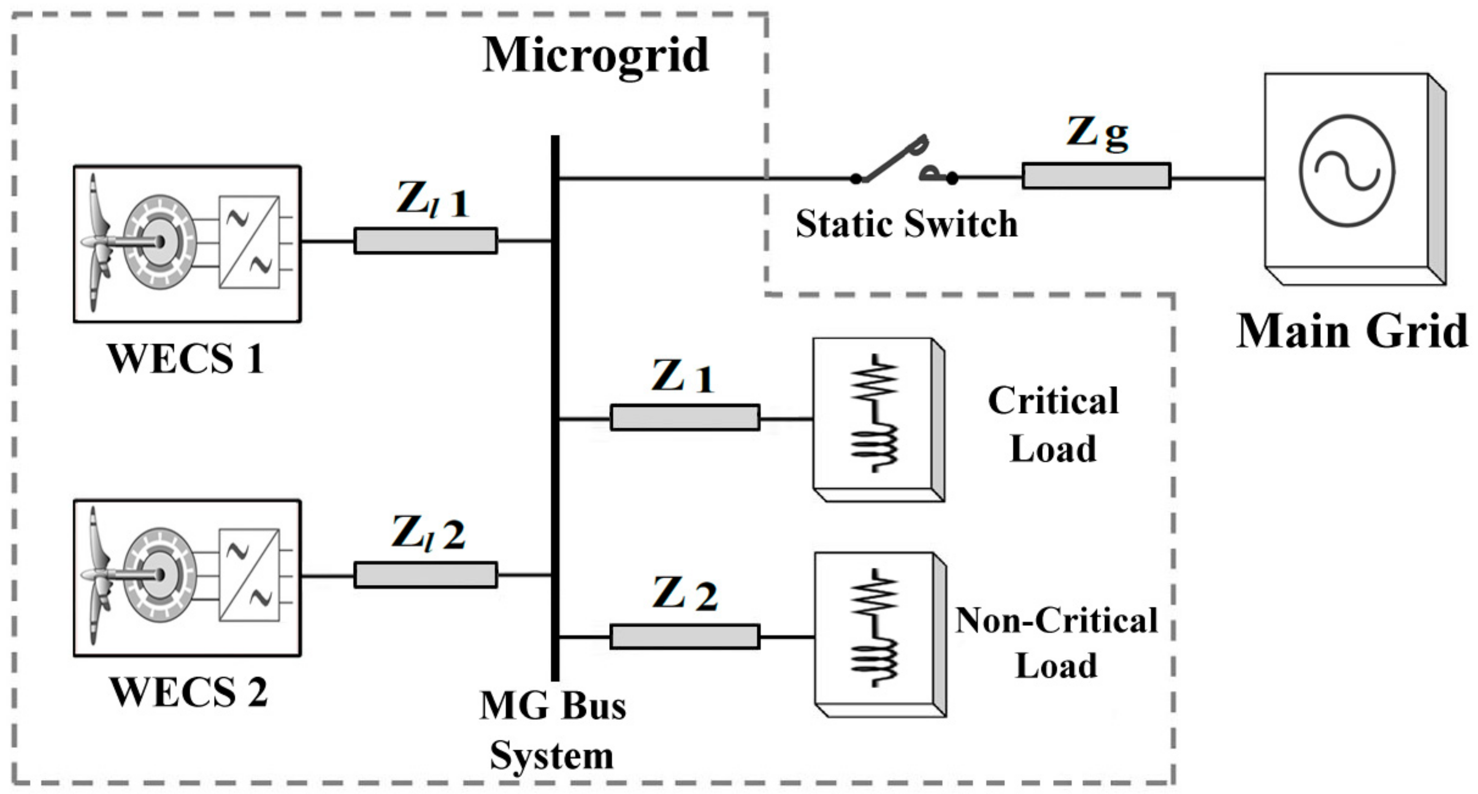
2. Structure of WECS-Based Microgrid

Figure 1 shows the typical structure for the WECS-based MG that contains two types of WECS connected to the same bus system with MG load. The main grid can be connected and disconnected to the MG bus system through the static switch. One unit from each type of WECS is used in this model, and a number of units can be added to each type in parallel. Both types of WECS are equipped with PMSGs because of the high efficiency and the compactness of PMSG, along with the recent popularity of using the PMSG, especially for offshore wind farms [28].

2.1. WECS 1: Battery-Backed WECS

The configuration of WECS 1 is shown in Figure 2. Because the pitch plate control is not our primary interest, it is not presented in this paper. The extracted electrical power from PMSG is injected to the DC-link via an uncontrolled rectifier and a boost converter. The benefits of this structure are its simplicity and cost reduction [29]. The control of the boost converter attempts to achieve the maximum power point by utilizing the lookup table of wind turbine characteristics, whereas the control of buck/boost converter attempts to keep the DC-link voltage constant and regulates the battery current on two sides. As long as this WECS is responsible for regulating voltage and frequency during islanded mode, the need for the battery is inevitable. With the battery rated capacity of 400 kWh and nominal voltage 800 V, the reference current for the battery Ibref is set to be:
I b r e f = K p b ( 850 V b ) + K i b ( 850 V b ) d t
where Kpb and Kib are the proportional and integral gains for battery current PI controller, respectively, and Vb is the voltage at the battery terminals.
For the grid-side converter (GSC), there is particular objective regarding each MG mode. The objective is attaining constant voltage and frequency for the MG load during autonomous mode. For grid-tied mode, the objective is providing the available active power or observing the required active power to charge the battery. Hence, to generate the current references, two different current control loops are used. The first loop is adjusting the current references based on two-stage hierarchical control. The second loop is mainly relying on the state of charge (SOC) during the grid-tied mode. Both loops will be illustrated in detail in Section 4. After achieving the current references in dq form, the next loop is the voltage regulating loop. Neglecting the effect of the filter capacitor, the output voltages from this loop can be clarified as:
V d o u t = V d ω L i q + K p d ( I d r e f I d ) + K i d ( I d r e f I d ) d t
V q o u t = ω L i d + K p q ( I q r e f I q ) + K i q ( I q r e f I q ) d t
where ωL is the compensation part of the filter inductor, Kpd, Kid, Kpq, and Kiq are the proportional and integral gains for direct and quadrature currents regulators, respectively.

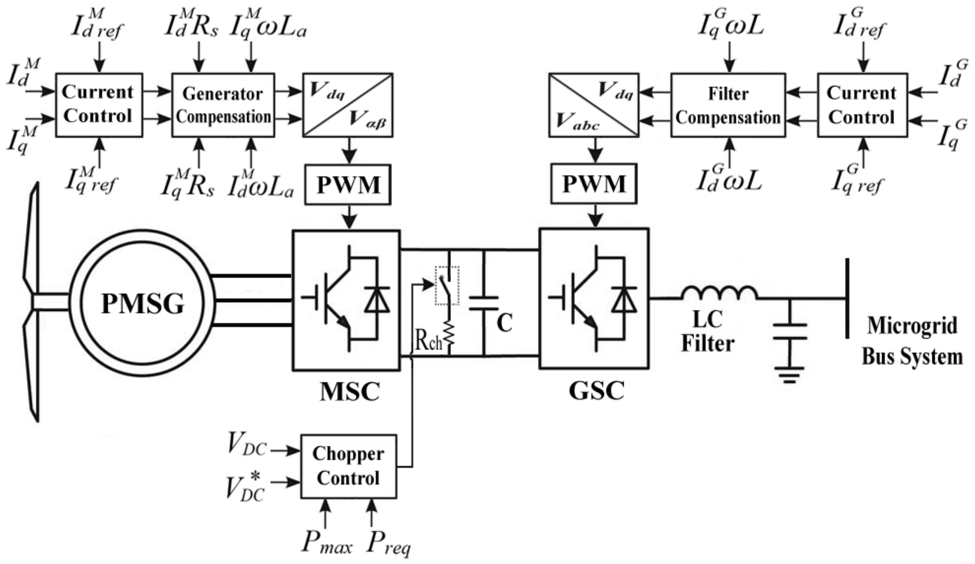
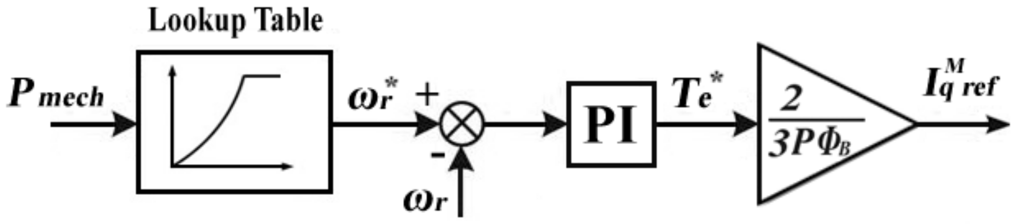
2.2. WECS 2: WECS Supported by Adaptive Operation

In this WECS, controlled converters are used in both machine and grid sides (see Figure 3). The machine-side converter (MSC) is utilized to elicit the maximum power generated by the wind turbine. The maximum power point tracking (MPPT) algorithm is used to evaluate the maximum active current Iq by utilizing the rotor speed ωr as shown in Figure 4. The reference currents of this converter in the dq rotating frame can be written as:
I d r e f M = 0
I q r e f M = 2 T e * 3 P ϕ B
where P is the number of pole pairs, ϕB is the magnetic flux of the generator, and Te* is the reference electrical torque and can be evaluated as:
T e * = K p T ( ω r * ω r ) + K i T ( ω r * ω r ) d t
where ωr* is the reference value of the rotor speed, KpT and KiT are the proportional and the integral gains for the torque regulator, respectively.
For GSC, as in WECS 1, it also has particular objectives regarding each MG mode. During grid-tied mode, the objective is to inject the maximum obtainable active power to the MG bus system and to regulate the DC-link voltage. Thus, the current references in dq form will be set as:
I d   r e f G = K p D C ( V D C * V D C ) + K i D C ( V D C * V D C ) d t
I q   r e f G = 0
where V*DC and VDC are the set value and the actual value for DC-link voltage, respectively, KpDC and KiDC are the proportional and the integral gains for the DC-link voltage regulator, respectively.
During autonomous mode, the maximum active power is not always required by the MG load. Sometimes, the generated active power is even higher than the required active power by the load and the available capacity in the battery of WECS 1. To avoid a power imbalance during autonomous mode, the adaptive operation is proposed in this paper. This approach selects the proper references for active and reactive currents. The active current reference can be set to choose the minimum of two values, namely, the maximum current and the required active current, as:
I d   r e f G = M i n { K p D C ( V D C * V D C ) + K i D C ( V D C * V D C ) d t 2 P r e q 3 V d }
where Preq is the active power required by MG load, and Vd is the direct axis voltage. In the case of setting the required active current as the reference, the surplus power in DC-link can be utilized in terms of the reactive power with consideration of the size of DC-link capacitor. The available reactive current can be clarified as:
I q a v l = [ K p D C ( V D C * V D C ) + K i D C ( V D C * V D C ) d t ] 2 [ 2 P r e q 3 V d ] 2
where Equation (10) can be achieved only when the maximum current is greater than the required active current. To ensure that the available reactive current is not greater than the required reactive current, the reactive current reference can be adjusted through PI regulator as:
I q   r e f G = K p r ( Q r e q Q a v l ) + K i r ( Q r e q Q a v l ) d t
where Kpr and Kir are the proportional and integral gains for the PI regulator, Qreq is the reactive power required by MG load, and Qavl is the available reactive power and can be evaluated as:
Q a v l = 3 2 V d I q a v l
Note that Qreq must be limited by Qavl as a maximum limit.
In the adaptive operation, when the required active current is selected, the DC-link voltage regulator will be inoperative. Thus, to adjust the DC voltage in this particular case, a chopper converter is utilized on the DC-link. The modulation signal for chopper Sch can be formed as:
S c h = K p c h ( V D C * 2 V D C 2 ) + K i c h ( V D C * 2 V D C 2 ) d t + ( P max P r e q ) 2 Q r e q 2 P c h
P c h = V D C 2 R c h
where Kpch and Kich are the proportional and integral gains for chopper regulator, respectively, Pch is the maximum chopper power, and Rch is the chopper resistance.

3. Two-Stage Hierarchical Control System
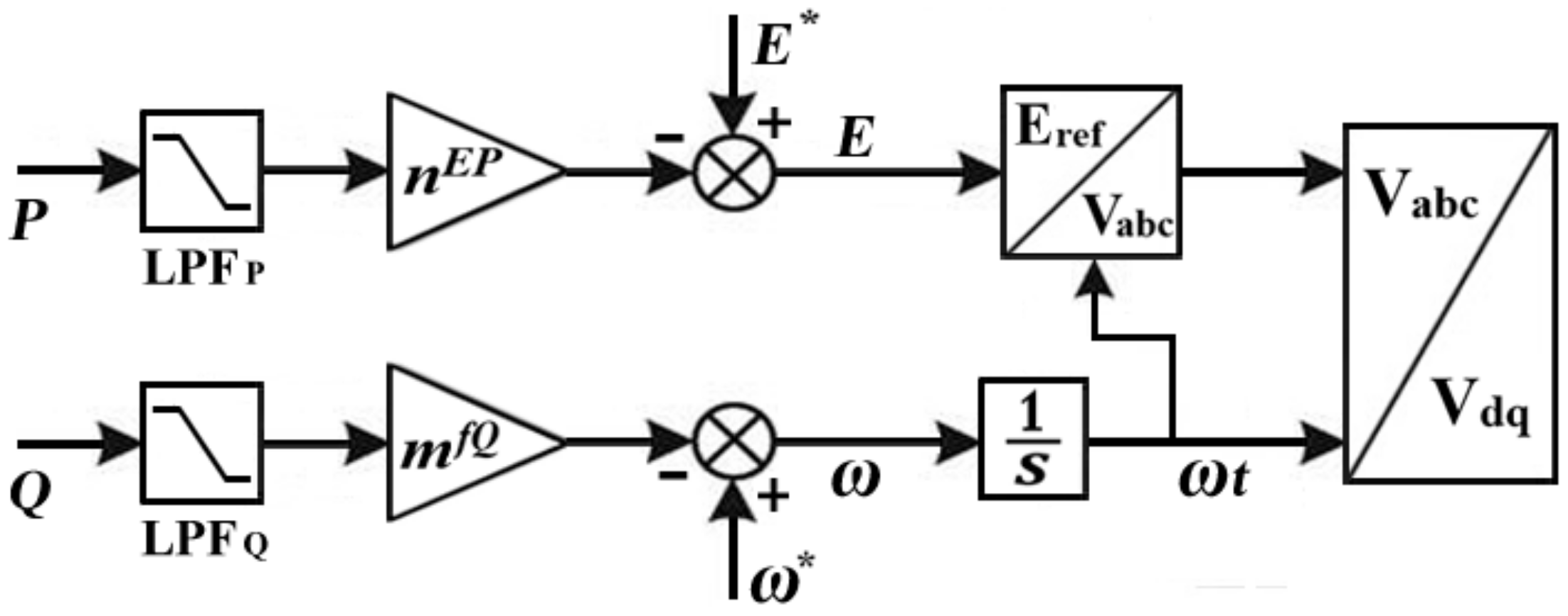
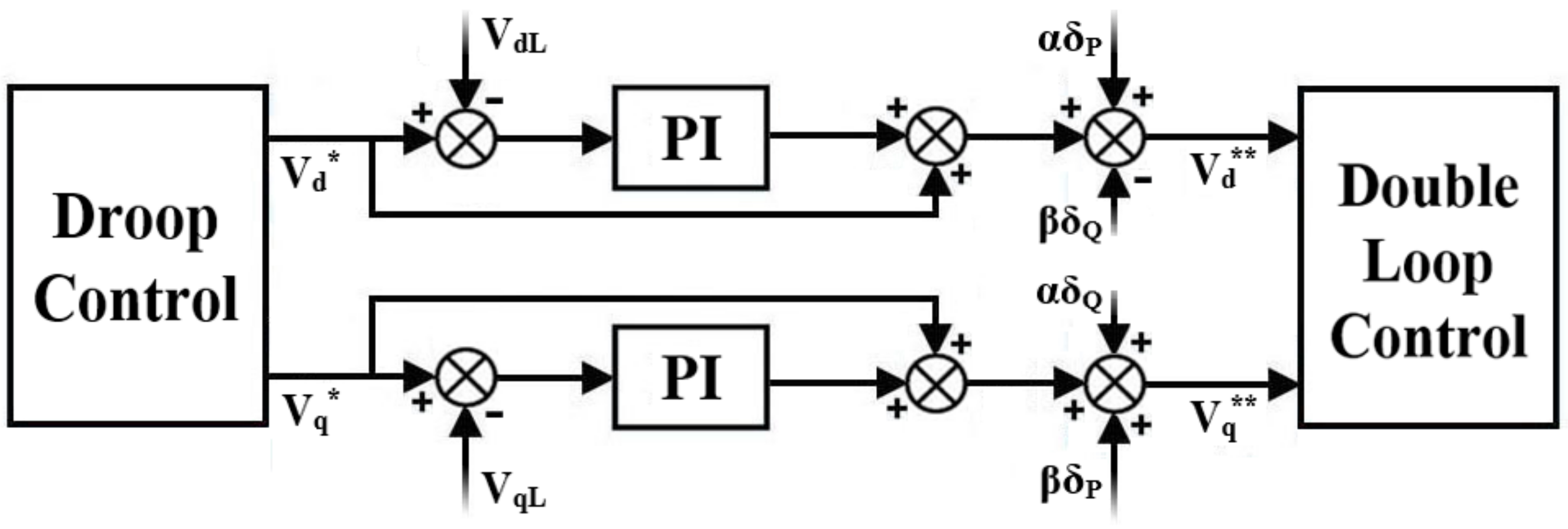
Based on the time response, the hierarchy gradient considers the droop control as the primary stage that handles sharing the active and reactive powers. The secondary stage is utilized to modify the primary stage output by compensating the perversions caused by the unknown line impedance.

3.1. Primary Stage

To emulate the behavior of the synchronous generator, the droop control for inverter-based DGs was investigated earlier in [30]. In this control method, the frequency is proportional to the active power alteration, while the voltage profile is linked to the alteration of reactive power. This method is modified to consider small systems, such as low-voltage MGs [27]. In such systems, the R/XL rate of line impedance is generally high (e.g., R/XL = 7.7 [31]). Therefore, the line impedance characteristics can be considered as mainly resistive. In a resistive line impedance system, the active and reactive powers can be clarified as follows:
P V E V 2 Z
Q V E Z φ
where E and V are the inverter output voltage and the grid voltage, respectively, Z is the line impedance, ϕ is the power angle. Note from Equations (15) and (16) that the active power is proportional to the voltage variation, while the reactive power is proportional to the power angle. Accordingly, the droop expressions can be written as Equations (17) and (18). Figure 5 illustrates the droop control for resistive line impedance system.
E * E = n E P P m e a s
w * w = m f Q Q m e a s
where E* and ω* are the preset voltage and frequency, respectively, nEP and mfQ are active and reactive droop slopes, respectively, and can be defined in Equations (19) and (20). Pmeas and Qmeas are the measured active and reactive powers, respectively, after passing through the low pass filter (LPF), and they can be obtained in Equations (21) and (22).
n E P = V max V min P max
m f Q = ω max ω min Q max
P m e a s = ω c ω c + s P
Q m e a s = ω c ω c + s Q
where Vmax, Vmin, ωmax, and ωmin are the maximum and minimum allowed limits of voltage and frequency, respectively, Pmax and Qmax are the maximum attainable active and reactive powers, respectively, and ωc is the cutoff frequency of LPF.

3.2. Secondary Stage

The critical loads in MG necessitate the deviation of voltage and frequency within the permissible limits during both load and generation changes. With the uncertainty of the line impedance, the droop control method does not meet this requirement without the support of a communication link [32]. The secondary stage is applied to compensate the deviations in voltage amplitude and frequency during the change of load or generation. The main idea is to compare the voltage and the frequency of the load to the reference values and inject the differences back to the primary stage through the PI controllers [21,26,33]. To reduce the intricacy of the communication link and to speed up the compensation, the load voltage and frequency in this study are converted to the dq rotating frame and compared with the outputs of primary stage as demonstrated in Figure 6. The resulting direct and quadrature voltages can be formed as:
V d * * = V d * + K p d sec ( V d * V d L ) + K i d sec ( V d * V d L ) d t
V q * * = V q * + K p q sec ( V q * V q L ) + K i q sec ( V q * V q L ) d t
where Vd** and Vq** are the new voltage references in dq form, Kpdsec, Kidsec, Kpqsec, and Kiqsec are the proportional and integral gains for direct and quadrature secondary controllers, respectively, and, VdL and VqL are load voltages in dq form. This method can reduce the steady-state error caused by primary stage faster than the traditional secondary method. However, the internal control loops will be more influenced during the large change in load. To overcome this trade-off, two damping terms of active and reactive loads (δP and δQ) are added to each of the direct and quadrature voltage references. The new voltage references are illustrated in Equations (25)–(28) with α and β as the adaptive gains for active and reactive loads damping and have been set to 0.6 and 0.2, respectively.
V d * * = V d * + K p d sec ( V d * V d L ) + K i d sec ( V d * V d L ) d t + α δ P β δ Q
V q * * = V q * + K p q sec ( V q * V q L ) + K i q sec ( V q * V q L ) d t + β δ P + α δ Q
δ P = { d P L d t if d P L d t > d P 1 d t + d P 2 d t 0       otherwise }
δ Q = { d Q L d t if d Q L d t > d Q 1 d t + d Q 2 d t 0       otherwise }
where P1 and Q1 are the output active and reactive powers of WECS1, respectively; P2 and Q2 are the output active and reactive powers of WECS2, respectively; and PL and QL are the load active and reactive powers, respectively. It is worth mentioning that the power losses in Equations (27) and (28) are neglected, thereby ensuring δP and δQ will both always be zero during the normal steady state condition.

3.3. Small Signal Analysis

Comprehensive small signal analysis for primary and secondary stages is presented in this part of the section. The small signal model for the primary stage can be achieved by linearizing Equations (17) and (18) as:
Δ E = n E P ω c s + ω c Δ P
Δ ω = m f Q ω c s + ω c Δ Q
where Δ refers to the small perturbation around the equilibrium point [26,34]. Equations (29) and (30) can be rearranged as:
s Δ E = ω c Δ E n E P ω c Δ P
s Δ ω = ω c Δ ω m f Q ω c Δ Q
By considering Equations (31) and (32) in the time domain, thus,
Δ E · = ω c Δ E n E P ω c Δ P
Δ ω · = ω c Δ ω m f Q ω c Δ Q
where the dotted variables refer to the derivate with respect to time. Considering the measuring filter, the output active and reactive powers of the inverter can be written in dq form as:
P = 3 ω c 2 ( ω c + s ) ( V d I d + V q I q )
Q = 3 ω c 2 ( ω c + s ) ( V q I d V d I q )
As the rotating axis is aligned with the output filter voltage (Vq = 0), the small model of active and reactive powers can be obtained as:
Δ P · = ω c Δ P + 3 ω c 2 I d 0 Δ V d + 3 ω c 2 V d 0 Δ I d
Δ Q · = ω c Δ Q 3 ω c 2 I q 0 Δ V d 3 ω c 2 V d 0 Δ I q
Because the compensation of secondary stage will be in the dq rotating frame, the droop control output can be obtained after the park transformation as Equations (39) and (40), (see Figure 5).
V d * = E [ sin 2 ( ω t ) sin ( ω t 2 π 3 ) cos ( ω t ) ]
V q * = E [ sin ( ω t ) cos ( ω t ) + sin ( ω t 2 π 3 ) sin ( ω t ) ]
Considering a small perturbation around the equilibrium point of (E = E*, ωt = π/2), Equations (39) and (40) can be linearized and expressed in Equations (41) and (42) after performing some mathematical operations.
Δ V d * · = Δ E · E * 2 Δ ω
Δ V q * · = 1 2 Δ E · + E * ( 3 2 1 ) Δ ω
By substituting Equation (33) in Equations (41) and (42), the state equation for primary control can be written as:
Δ V d * · = ω c Δ E n E P ω c Δ P E * 2 Δ ω
Δ V q * · = ω c 2 Δ E + n E P ω c 2 Δ P + E * ( 3 2 1 ) Δ ω
For secondary control, with considering the transient terms (δP and δQ) are equal to zero, Equations (25) and (26) can be linearized and expressed in Equations (45) and (46) after performing some mathematical operations.
Δ V d * * · = ( 1 + K p d sec ) Δ V d * · + K i d sec Δ V d *
Δ V q * * · = ( 1 + K p q sec ) Δ V q * · + K i q sec Δ V q *
By substituting Equations (43) and (44) in Equations (45) and (46), thus,
Δ V d * * · = K i d sec Δ V d * ω c ( 1 + K p d sec ) Δ E n E P ω c ( 1 + K p d sec ) Δ P E * 2 ( 1 + K p d sec ) Δ ω
Δ V q * * · = K i q sec Δ V q * + ω c 2 ( 1 + K p q sec ) Δ E + n E P ω c 2 ( 1 + K p q sec ) Δ P + E * ( 3 2 1 ) ( 1 + K p q sec ) Δ ω
By considering the state vector for the state-space model as [ΔE Δω ΔVd* ΔVq* ΔVd** ΔVq** ΔP ΔQ]T, and [ΔVd ΔId ΔIq]T as the input vector and using the parameters of Table 1, the eigenvalues of the system can be defined In Equation (49), where they lie on the left side of the S-plane.
λ 1 = λ 2 = λ 7 = λ 8 = 37.7 ,    λ 3 = λ 4 = λ 5 = λ 6 = 0

4. Formulation of Mode Transition

In this section, the formulation of the mode transition is described basically for WECS1. Two major cases are considered: unplanned grid-tied to autonomous transition and the transition of planned reconnection to the main grid. In each case, the transition strategy must be designed to satisfy the requirement for a smooth transition while avoiding any out of limits operating conditions.

4.1. From Grid-Tied to Autonomous

In this transition, two aspects require serious attention: the fast problem announcement to avoid system deterioration and the appropriate adaptation to the new mode. When the MG operates in a grid-tied mode, the objective of WECS1 is injecting the available active power or observing the required active power to charge the battery. Meanwhile, the phase locked loop (PLL) can equip the synchronization with the main grid. Hence, the current references can be obtained as follows:
I d r e f = { ( I c h I P M S G ) for S O C 20 % 0 for 20 % < S O C < 90 % I c h for S O C 90 % }
I q r e f = 0
where Ich and IPMSG are nominal charging current of the battery and rectified PMSG output current, respectively. Note that the reactive current is set to zero during grid-tied mode; thus, the reactive load will be supplied by the main grid side.
When an abnormal condition occurs (i.e., fault condition or severe deviation in voltage or frequency), the MG must separate from the main grid and operate in autonomous mode. To acclimate with the new mode, the MG control strategy needs to be changed to the forming voltage-frequency strategy aiming to keep voltage and frequency controlled by the two-stage hierarchical control. The fault detection relay is responsible for judging the transfer instant where this relay is providing two signals. The first signal is supposed to be delivered to WECS1 to change the control strategy, and the second signal is responsible for switching off the static switch. Further, the adaptation to the new mode necessitates a suitable methodology to ensure the synchronizing components (voltage, frequency, and phase angle) remain within the operating limits. The main reason behind the deviation of the synchronizing components is the sudden unbalance between the load of MG and the output of DGs. Consequently, the key idea of achieving a smooth transition in this paper relies on satisfying rapid compensation for the required active and reactive currents. First, the currents of the main grid in dq form are evaluated and compared with the output currents of the inverter. Second, the differences in currents are injected into the main current regulator after passing through PI controller, as shown in Figure 7. The measured values of main grid active and reactive currents must be saved in temporary memory at the outage moment. Once the inputs of PI controller equal to zero, the compensator must be switched off, leaving the current regulator working in the forming voltage-frequency strategy. Hence, the current references can be obtained as:
I d r e f = I d V F = K p d ( V d * * V d ) + K i d ( V d * * V d ) d t
I q r e f = I q V F = K p q ( V q * * V q ) + K i q ( V q * * V q ) d t
where Id VF and IqVF are the direct and quadrature current references in the forming voltage-frequency strategy, Kpd, Kid, Kpq, and Kiq are the proportional and integral gains for direct and quadrature current regulators, respectively.

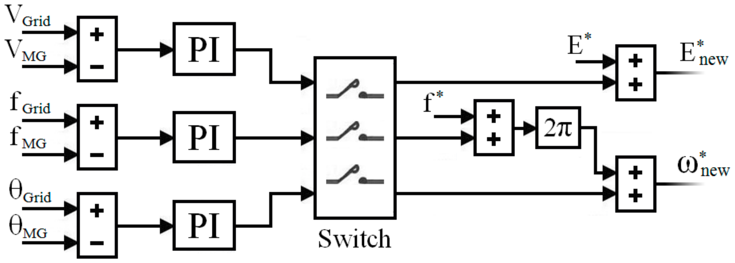
4.2. From Autonomous to Grid-Tied

Once the main grid returns to its normal condition, the MG has enough time to become synchronized with the main grid before closing the static switch. The pre-synchronization method is a well-qualified method to get the synchronizing components of MG to be within the limits of their counterparts in the main grid [35,36]. As the control strategy in autonomous mode is ruled by the droop control, the preset values of voltage and frequency in droop control must be modified to coincide with the voltage and frequency of the main grid. To synchronize the MG with the main grid, three error components are added to the active and reactive power loops in droop control, as shown in Figure 8. Where E*new and ω*new in Figure 8 are the new preset voltage and angular frequency of droop control, respectively. VGrid, θGrid, fGrid, VMG, θMG, and fMG are voltages, phase angles, and frequencies of grid side and MG side, respectively. By tuning accurate gains for PI controllers, the time spent for synchronization will be minimized. The PI gains of voltage component can be tuned separately, whereas the PI gains of frequency and phase angle components must be tuned together because they may influence each other. Once the inputs of PI controllers equal to zero, the MG will reconnect to the main grid through the static switch and the control strategy will be changed at the same time. The main grid voltage during synchronization often includes some harmonics; therefore, an LPF is utilized to extract the main grid voltage with the fundamental frequency. A related point to be mentioned in this transition is that, as the references of the secondary stage are the outputs of droop control in dq form, there is no need to disable the secondary stage throughout the synchronization process.

5. Simulation Results

To evaluate the effectiveness of the proposed work, WECS-based MG shown in Figure 1 is modeled in the MATLAB/Simulink environment. The design parameters of the system are shown in Table 2 based on typical values for low-voltage systems with an R/XL rate of line impedance is nearly equal to 6 [27,32]. Table 3 shows the control parameters for the entire system, and they have been defined by the trial and error (TAE) method after an extensive number of iterations to ensure the best convergence of the controlled components to the desired values.

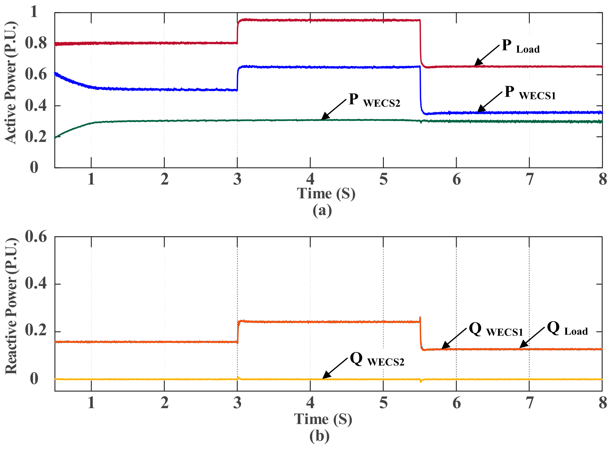
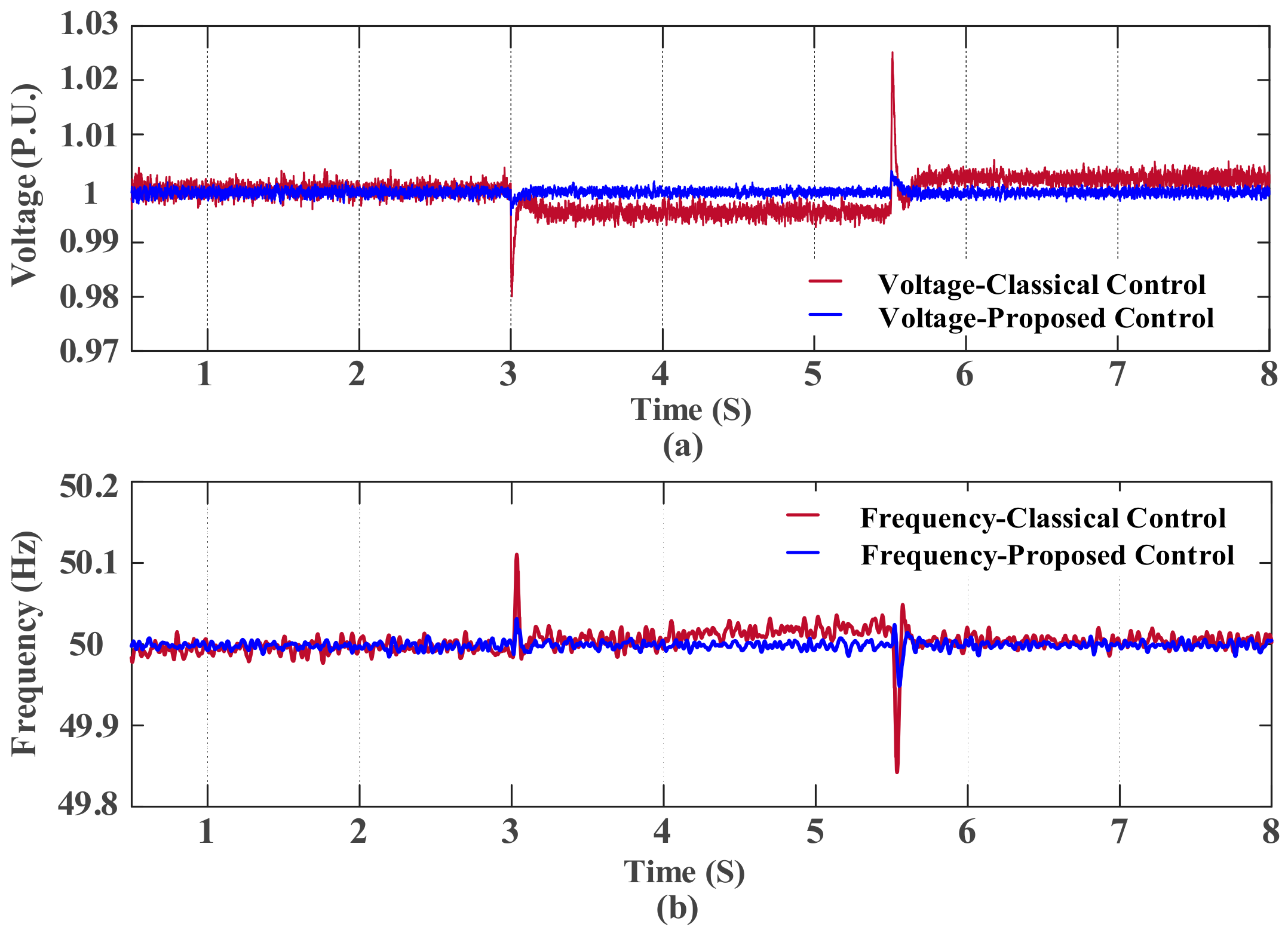
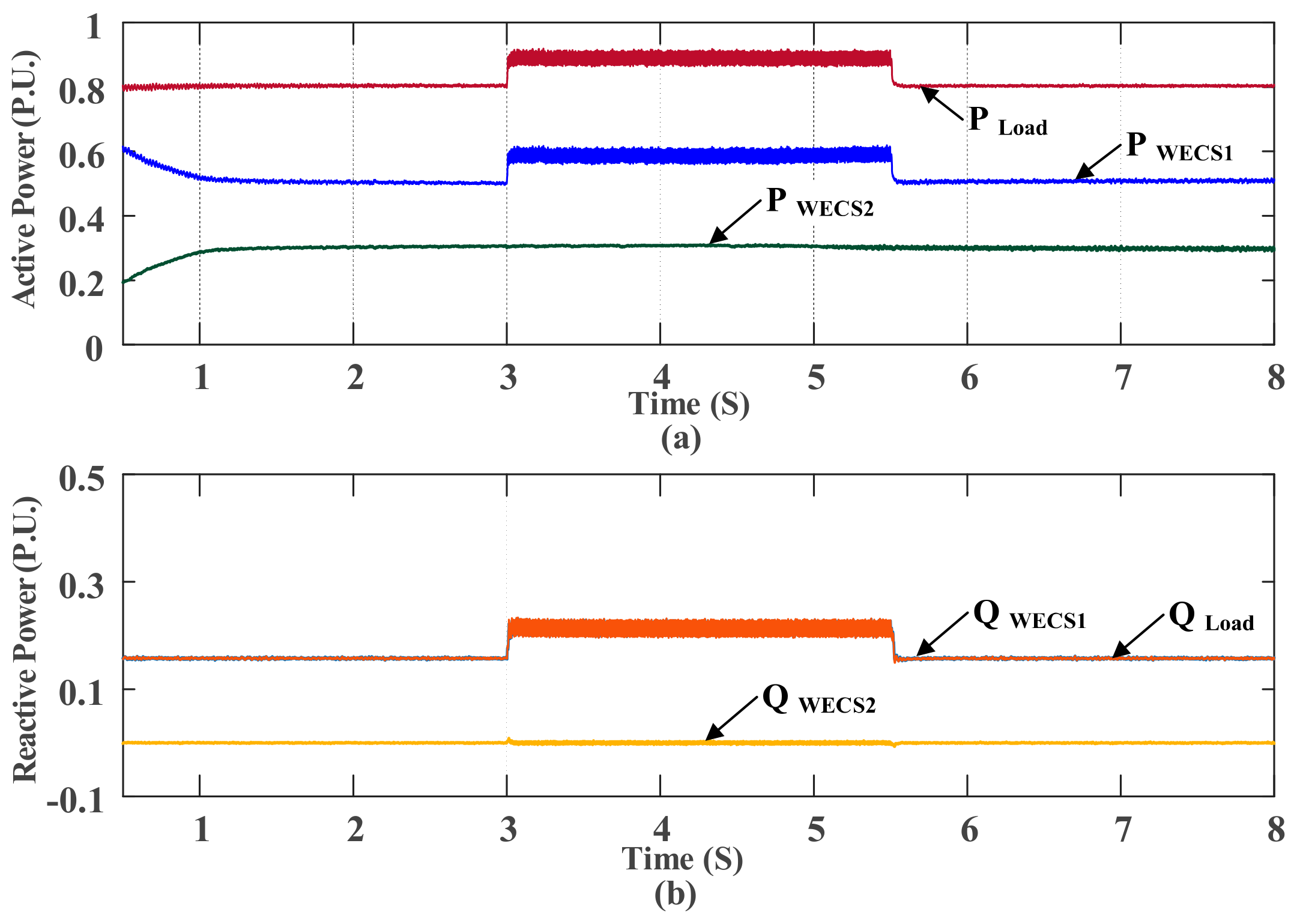
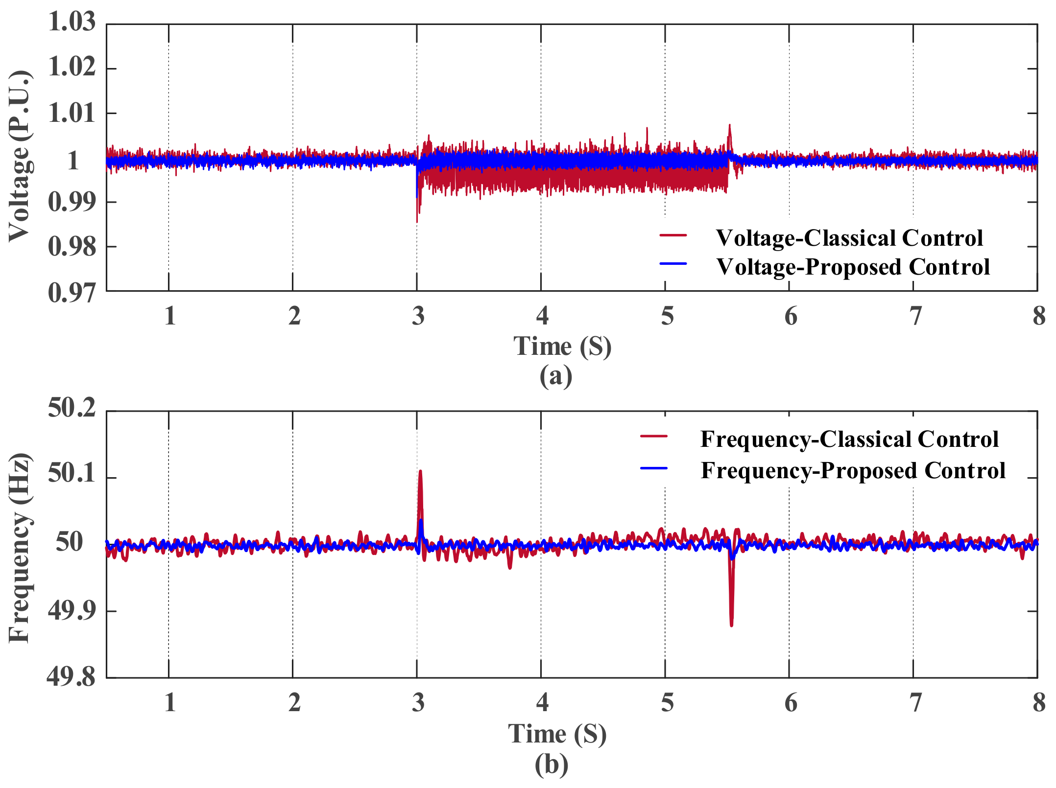
5.1. Mitigate the Deviations during Large Changes in Load

Assuming that the MG is operating in autonomous mode, for this scenario, the output of WECS2 is considered to be constant. The performance of the proposed secondary control is evaluated under balanced and unbalanced load changes. Figure 9 shows the output active and reactive powers of both WECS1 and WECS2 as they are responding to the balanced load change. An additional load of 0.162 + j0.1 PU is added at t = 3 s, and another load of 0.323 + j0.133 PU is suddenly removed at t = 5.5 s. The responses of voltage and frequency caused by the restoration by classical secondary control [21] due to balanced load changes are shown in Figure 10 with a red line. It can be seen that both postures of voltage and frequency are deviating in the permitted limits. However, the low damping has led to an overshoot during large load change, even with the best-tuned gains of current regulators. The responses of voltage and frequency caused by the restoration via the proposed control due to a balanced load change are shown in Figure 10 with a blue line. Similarly, to evaluate the performance of the proposed control under unbalanced load changes, an unbalanced load (phase A: 0.162 + j0.1 PU, phase B: 0.12 + j0.075 PU, phase C: 0 + j0 PU) is added and removed at t = 3 s and t = 5.5 s, respectively. Figure 11 shows the output active and reactive powers of both WECS1 and WECS2 as they are responding to the unbalanced load change. Figure 12 clarifies the voltage and frequency responses during the unbalanced load changes with the restoration by the classical and proposed control methods. Comparing the responses of the proposed control to that of classical control, for both balanced and unbalanced load changes, it can be seen that the deviations have been clearly mitigated via the direct compensation. Moreover, it significantly verifies the effectiveness of the damping terms during load change (t = 3 s and t = 5.5 s). Thus, the additional terms have evidently damped the overshoot for the same gains of current regulators.

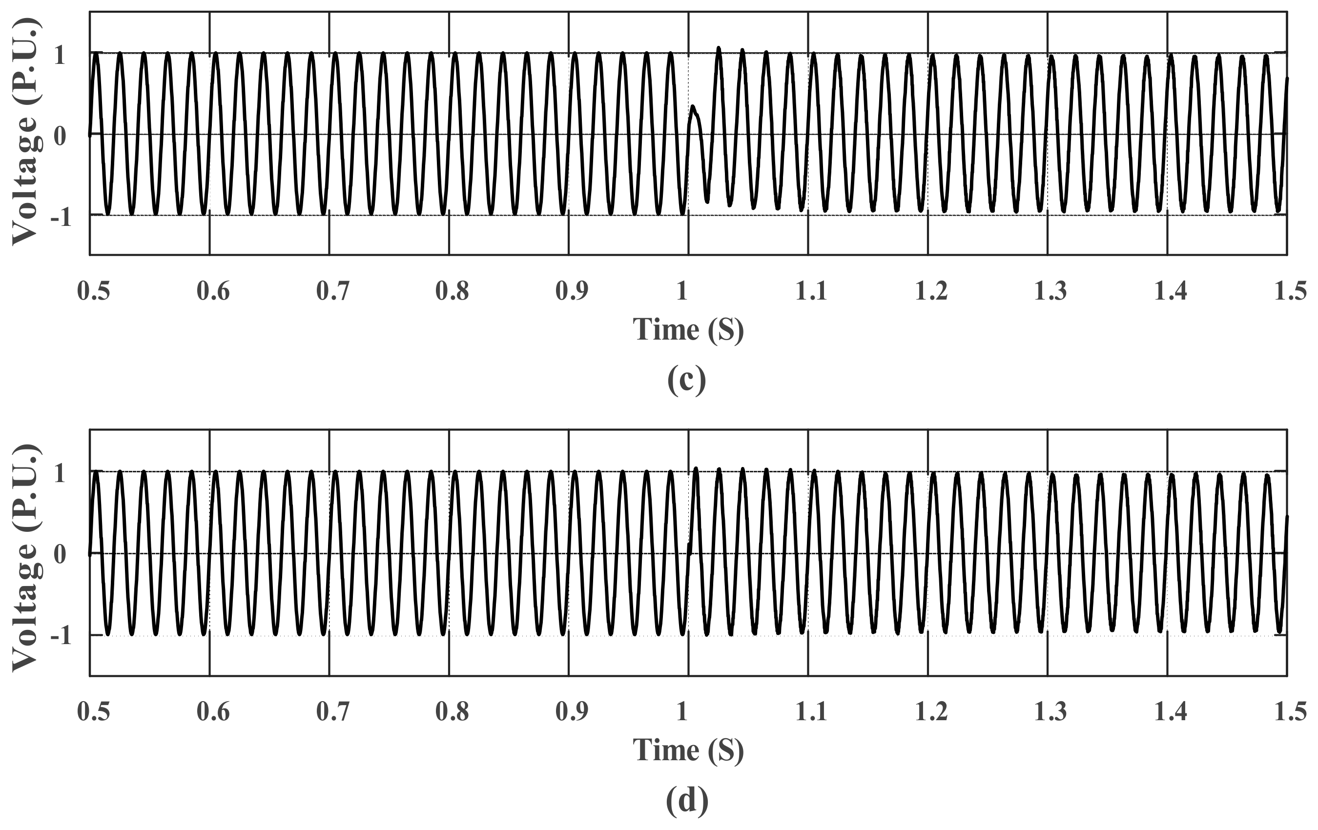
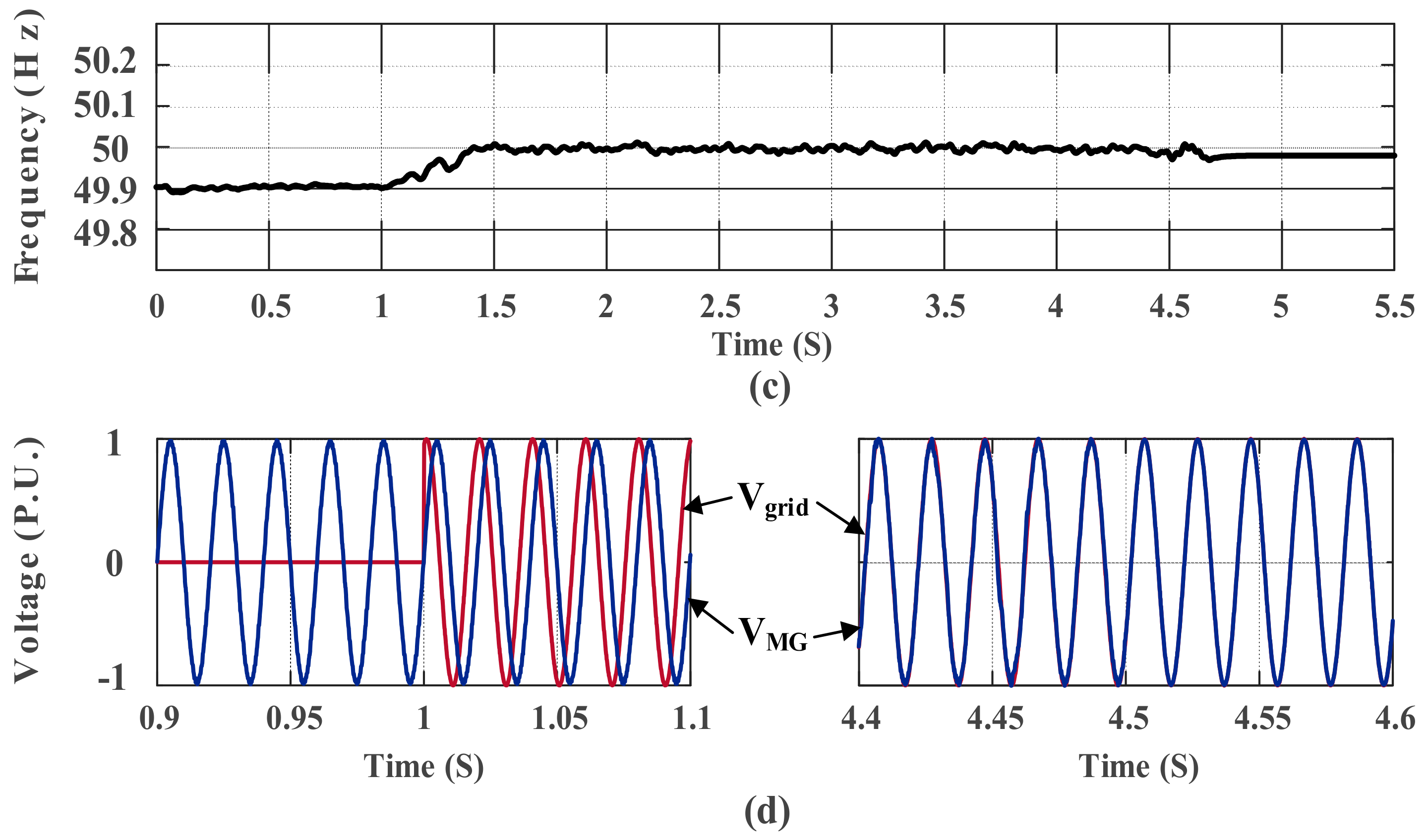
5.2. Smooth Mode Transition between Grid-Tied and Autonomous

For the outage scenario, the MG is supposed to be operated in grid-tied mode. The SOC is set within the range of charging the battery only from PMSG (Case 2 in Equation (50)). Accordingly, the active and reactive loads of MG that could not be supplied by WECS2 are supplied from the main grid side. An outage of the main grid is assumed to occur at t = 1 s. At the outage moment, the control strategy of WECS1 is changed to the forming voltage-frequency strategy. When the outage occurred, the available output power in MG is sufficient to feed the local load; thus, no load shedding is required. Figure 13a,b shows the active and reactive currents of the main grid at the point of common coupling (PCC), with and without the proposed method. The proposed method is found to reduce the large transient in current, as is significantly reflected in the response of MG voltage. Figure 13c,d shows the response of MG voltage during the transition with and without the proposed method.
For reconnection scenario, WECS1 is set to operate in the forming voltage-frequency strategy under autonomous mode. It is assumed that the main grid returned to its normal condition at t = 0.5 s. For verification purpose, all the synchronizing components of the MG are supposed to have variances with their counterparts in the main grid. To confirm the tying of main grid and to override the low-quality interval, a delay of 0.5 s is specified before starting the pre-synchronization procedure. Accordingly, the switches of all compensators have closed at t = 1 s. The responses of RMS voltage and frequency through the synchronization are shown in Figure 14b,c. The variance in phase angle before and after the synchronization is shown in Figure 14d. The timing sequence for synchronization is defined as follow. The variation in frequency of 0.1 Hz has been eliminated after 0.5 s. The variation in voltage of 8 V is reduced to zero after 1.3 s. Then, the difference in phase angle which is 6° has been adjusted to zero after 3.5 s. Therefore, at t = 4.5 s, the control strategy is changed back, and the static switch of MG is closed. The main grid started supplying the MG load after t = 4.5 s, as shown in Figure 14a. The results demonstrate that the pre-synchronization method allows the perfect tracking for the main grid synchronizing components and ensures the smooth reconnection to the main grid.

6. Conclusions

This paper presented an investigation into the modeling of an enhanced control stand on the two-stage hierarchical structure for WECS-based MG. The MG configuration was comprised of two types of WECSs with particular features for each type. WECS1 is utilized to extract the maximum power during both modes and support the system frequency during autonomous mode; thus, it is supposed to be backed with a battery. For WECS2, as it is assumed to be free of a battery, it was supported by a proposed adaptive operation to avoid power unbalance and provide system flexibility. In terms of hierarchical structure, the primary stage utilized the P-V/Q-f droop method, which is the preferred method to be used in MGs with mainly resistive line impedance, whereas the secondary stage relied on an enhanced methodology for compensating the deviations of voltage and frequency in the dq rotating frame. Moreover, two damping terms were added to each loop in the secondary stage to assist in the overshoot damping during a large change in load. Furthermore, a small signal analysis was performed to evaluate the eigenvalues and validate the stability of the proposed control. In the aspect of mode transition, the robust controls for both the unplanned outage transition and the pre-synchronization and reconnection transition were proposed and investigated to clarify their features. The proposed approach was proven to be effective by the simulation results: firstly, for a small signal and large signal disturbances with a comparison to the conventional control method and secondly, for both formulations of mode transition presented.

Author Contributions

The paper was a collaborative effort between both authors. R.M.I. performed the theoretical analysis, provided the simulation verification, and wrote the manuscript. S.W. provided the research direction, supervised the entire research process, and edited the manuscript.

Acknowledgments

The authors would like to acknowledge the State Key Laboratory of Advanced Electromagnetic Engineering and Technology, Huazhong University of Science and Technology for providing the essential facilities.

Conflicts of Interest

The authors declare no conflict of interest.

References

  1. Singh, M.; Chandra, A. Application of adaptive network-based fuzzy inference system for sensorless control of PMSG-based wind turbine with nonlinear-load-compensation capabilities. IEEE Trans. Power Electron. 2011, 26, 165–175. [Google Scholar] [CrossRef]
  2. Olivares, D.E.; Mehrizi-Sani, A.; Etemadi, A.H.; Canizares, C.A.; Iravani, R.; Kazerani, M.; Hajimiragha, A.H.; Gomis-Bellmunt, O.; Saeedifard, M.; Palma-Behnke, R.; et al. Trends in microgrid control. IEEE Trans. Smart Grid 2014, 5, 1905–1919. [Google Scholar] [CrossRef]
  3. Giraldo, J.; Mojica-Nava, E.; Quijano, N. Synchronization of isolated microgrids with a communication infrastructure using energy storage systems. Int. J. Electron. Power Energy Syst. 2014, 63, 71–82. [Google Scholar] [CrossRef]
  4. Tang, X.; Hu, X.; Li, N.; Deng, W.; Zhang, G. A novel frequency and voltage control method for islanded microgrid based on multienergy storages. IEEE Trans. Smart Grid 2016, 7, 410–419. [Google Scholar] [CrossRef]
  5. Mahmud, M.; Hossain, M.; Pota, H.; Oo, A. Robust nonlinear distributed controller design for active and reactive power sharing in islanded microgrids. IEEE Trans. Energy Convers. 2014, 29, 893–903. [Google Scholar] [CrossRef]
  6. Savaghebi, M.; Vasquez, J.C.; Jalilian, A.; Guerrero, J.M.; Lee, T.L. Selective compensation of voltage harmonics in grid-connected microgrids. Math. Comput. Simul. 2013, 91, 211–228. [Google Scholar] [CrossRef]
  7. Avelar, H.J.; Parreira, W.A.; Vieira, J.B.; de Freitas, L.C.G.; Coelho, E.A.A. A state equation model of a single-phase grid-connected inverter using a droop control scheme with extra phase shift control action. IEEE Trans. Ind. Electron. 2012, 59, 1527–1537. [Google Scholar] [CrossRef]
  8. Guerrero, J.M.; Vasquez, J.C.; Matas, J.; Castilla, M.; de Vicuña, L.G. Control strategy for flexible microgrid based on parallel line-interactive UPS systems. IEEE Trans. Ind. Electron. 2009, 56, 726–736. [Google Scholar] [CrossRef]
  9. Xin, H.; Zhang, L.; Wang, Z. Control of island AC microgrids using a fully distributed approach. IEEE Trans. Smart Grid 2015, 6, 943–945. [Google Scholar] [CrossRef]
  10. Arboleya, P.; Gonzalez-Moran, C.; Coto, M.; Falvo, M.C.; Martirano, L.; Sbordone, D.; Bertini, I.; Di Pietra, B. Efficient energy management in smart micro-grids: ZERO grid impact buildings. IEEE Trans. Smart Grid 2015, 6, 1055–1063. [Google Scholar] [CrossRef]
  11. Ding, G.; Gao, F.; Zhang, F. Control of hybrid AC/DC microgrid under islanding operational conditions. J. Mod. Power Syst. Clean Energy 2014, 2, 223–232. [Google Scholar] [CrossRef]
  12. Bidram, A.; Davoudi, A. Hierarchical structure of microgrids control system. IEEE Trans. Smart Grid 2012, 3, 1963–1976. [Google Scholar] [CrossRef]
  13. He, J.; Li, Y.W. Analysis, design, and implementation of virtual impedance for power electronics interfaced distributed generation. IEEE Trans. Ind. Appl. 2011, 47, 2525–2538. [Google Scholar] [CrossRef]
  14. Liu, Q.; Tao, Y.; Liu, X.H.; Deng, Y.; He, X.G. Voltage unbalance and harmonics compensation for islanded microgrid inverters. IET Power Electron. 2013, 7, 1055–1063. [Google Scholar] [CrossRef]
  15. Tao, Y.; Liu, Q.W.; Deng, Y.; Liu, X.H.; He, X.G. Analysis and mitigation of inverter output impedance impacts for distributed energy resource interface. IEEE Trans. Power Electron. 2015, 30, 3563–3576. [Google Scholar] [CrossRef]
  16. He, J.; Li, Y.W. An enhanced microgrid load demand sharing strategy. IEEE Trans. Power Electron. 2012, 27, 3984–3995. [Google Scholar] [CrossRef]
  17. Mahmood, H.; Michaelson, D.; Jiang, J. Reactive power sharing in islanded microgrids using adaptive voltage droop control. IEEE Trans. Smart Grid 2015, 6, 3052–3060. [Google Scholar] [CrossRef]
  18. Shafiee, Q.; Guerrero, J.M.; Vasquez, J.C. Distributed secondary control for islanded microgrids—A novel approach. IEEE Trans. Power Electron. 2014, 29, 1018–1031. [Google Scholar] [CrossRef]
  19. Lu, X.; Guerrero, J.M.; Sun, K.; Vasquez, J.C.; Teodorescu, R.; Huang, L. Hierarchical control of parallel AC-DC converter interfaces for hybrid microgrids. IEEE Trans. Smart Grid 2014, 5, 683–692. [Google Scholar] [CrossRef]
  20. Savaghebi, M.; Hashempour, M.M.; Guerrero, J.M. Hierarchical coordinated control of distributed generators and active power filters to enhance power quality of microgrids. In Proceedings of the 2014 55th International Scientific Conference on Power and Electrical Engineering of Riga Technical University (RTUCON), Riga, Latvia, 14 October 2014; pp. 259–264. [Google Scholar]
  21. Baghaee, H.R.; Mirsalim, M.; Gharehpetian, G.B. Power calculation using RBF neural networks to improve power sharing of hierarchical control scheme in multi-DER microgrids. IEEE J. Emerg. Sel. Top. Power Electron. 2016, 4, 1217–1225. [Google Scholar] [CrossRef]
  22. Wu, D.; Tang, F.; Dragicevic, T.; Vasquez, J.; Guerrero, J. Autonomous active power control for islanded ac microgrids with photovoltaic generation and energy storage system. IEEE Trans. Energy Convers. 2014, 29, 882–892. [Google Scholar] [CrossRef]
  23. Han, H.; Liu, Y.; Sun, Y.; Su, M.; Guerrero, J.M. An improved droop control strategy for reactive power sharing in islanded microgrid. IEEE Trans. Power Electron. 2015, 30, 3133–3141. [Google Scholar] [CrossRef]
  24. Zhao, Z.; Yang, P.; Guerrero, J.M.; Xu, Z.; Green, T.C. Multiple-time-scales hierarchical frequency stability control strategy of medium-voltage isolated microgrid. IEEE Trans. Power Electron. 2016, 31, 5974–5991. [Google Scholar] [CrossRef]
  25. Guerrero, J.M.; Chandorkar, M.; Lee, T.-L.; Loh, P.C. Advanced control architectures for intelligent microgrids—Part I: Decentralized and hierarchical control. IEEE Trans. Ind. Electron. 2013, 60, 1254–1262. [Google Scholar] [CrossRef]
  26. Han, Y.; Shen, P.; Zhao, X.; Guerrero, J.M. Control strategies for islanded microgrid using enhanced hierarchical control structure with multiple current-loop damping schemes. IEEE Trans. Smart Grid 2017, 8, 1139–1153. [Google Scholar] [CrossRef]
  27. Guerrero, J.; Matas, J.; de Vicuna, L.G.; Castilla, M.; Miret, J. Decentralized control for parallel operation of distributed generation inverters using resistive output impedance. IEEE Trans. Ind. Electron. 2007, 54, 994–1004. [Google Scholar] [CrossRef]
  28. Li, Y.; Xu, Z.; Wong, K.P. Advanced control strategies of PMSG-based wind turbines for system inertia support. IEEE Trans. Power Syst. 2017, 32, 3027–3037. [Google Scholar] [CrossRef]
  29. Mozayan, S.M.; Saad, M.; Vahedi, H.; Fortin-Blanchette, H.; Soltani, M. Sliding mode control of PMSG wind turbine based on enhanced exponential reaching law. IEEE Trans. Ind. Electron. 2016, 63, 6148–6159. [Google Scholar] [CrossRef]
  30. Chandorkar, M.C.; Divan, D.M.; Adapa, R. Control of parallel connected inverters in standalone AC supply systems. IEEE Trans. Ind. Appl. 1993, 29, 136–143. [Google Scholar] [CrossRef]
  31. La Bella, A.; Cominesi, S.R.; Sandroni, C.; Scattolini, R. Hierarchical Predictive Control of Microgrids in Islanded Operation. IEEE Trans. Autom. Sci. Eng. 2017, 14, 536–546. [Google Scholar] [CrossRef]
  32. Vandoorn, T.L.; De Kooning, J.D.M.; Meersman, B.; Guerrero, J.M.; Vandevelde, L. Automatic power-sharing modification of P/V droop controllers in low-voltage resistive microgrids. IEEE Trans. Power Deliv. 2012, 27, 2318–2325. [Google Scholar] [CrossRef] [Green Version]
  33. Yao, G.; Lu, Z.; Wang, Y.; Benbouzid, M.; Moreau, L. Virtual Synchronous Generator Based Hierarchical Control Scheme of Distributed Generation Systems. Energies 2017, 10, 2049. [Google Scholar] [CrossRef]
  34. Coelho, E.A.A.; Cortizo, P.C.; Garcia, P.F.D. Small-signal stability for parallel-connected inverters in stand-alone AC supply systems. IEEE Trans. Ind. Appl. 2002, 38, 533–542. [Google Scholar] [CrossRef]
  35. Zhang, T.; Yue, D.; O’Grady, M.J.; O’Hare, G.M.P. Transient oscillations analysis and modified control strategy for seamless mode transfer in micro-grids: A wind-PV-ES hybrid system case study. Energies 2015, 8, 13758–13777. [Google Scholar] [CrossRef]
  36. Chen, Z.; Zhang, W.; Cai, J.Q.; Cai, T.; Xu, Z.Q.; Yan, N. A synchronization control method for micro-grid with droop control. In Proceedings of the 2015 IEEE Energy Conversion Congress and Exposition (ECCE), Montreal, QC, Canada, 20–24 September 2015; pp. 519–524. [Google Scholar]
Figure 1. Typical structure for the wind energy conversion system (WECS) microgrid (MG).
Energies 11 01270 g001
Figure 2. Structure and control system of WECS 1.
Energies 11 01270 g002
Figure 3. Structure and control system of WECS 2.
Energies 11 01270 g003
Figure 4. Block diagram of obtaining the maximum Iq in the machine-side converter (MSC).
Energies 11 01270 g004
Figure 5. Block diagram of utilized droop control.
Energies 11 01270 g005
Figure 6. Proposed secondary control.
Energies 11 01270 g006
Figure 7. Transition control for unplanned outage.
Energies 11 01270 g007
Figure 8. Pre-synchronization scheme of droop control.
Energies 11 01270 g008
Figure 9. Balanced load change during autonomous mode: (a) Active power posture; (b) Reactive power posture.
Energies 11 01270 g009
Figure 10. Restorations performance of secondary stage during balanced load change: (a) Voltage response; (b) Frequency response.
Energies 11 01270 g010
Figure 11. Inserting unbalanced load during autonomous mode: (a) Active power posture; (b) Reactive power posture.
Energies 11 01270 g011
Figure 12. Restorations performance of secondary stage during unbalanced load change: (a) Voltage response; (b) Frequency response.
Energies 11 01270 g012
Figure 13. Simulation results of unplanned outage transition: (a) Main grid currents without the proposed method; (b) Main grid currents with the proposed method; (c) MG voltage without the proposed method (d) MG voltage with the proposed method.
Energies 11 01270 g013aEnergies 11 01270 g013b
Figure 14. Simulation results of synchronization and reconnection to the main grid: (a) Active and reactive powers absorbed from main grid; (b) MG voltage; (c) MG frequency; (d) The difference in phase angle before the synchronization (0.9 s to 1.1 s) and after the synchronization (4.4 s to 4.6 s).
Energies 11 01270 g014aEnergies 11 01270 g014b
Table 1. Parameters of primary and secondary stages.
ParameterSymbolValue
Cut-off frequency of measuring filterωc12π rad/s
Voltage droop slopenEP0.0008 V/W
Frequency droop slopemfQ0.0006 rad/s/VAr
Proportional gain-D axis-Secondary controllerKpdsec2.4
Integral gain-D axis-Secondary controllerKidsec10
Proportional gain-Q axis-Secondary controllerKpqsec1.8
Integral gain-Q axis-Secondary controllerKiqsec8
Preset voltage of droop controlE*390 V
Table 2. System Sizing and Parameters.
ParameterValue
System Sizing
WECS1360 kVA
WECS2300 kVA
Battery400 kWh
System Parameters
Grid voltage (L-L)480 V
Grid frequency50 Hz
Line impedance (Zl1)0.14 + j0.021 Ω
Line impedance (Zl2)0.12 + j0.018 Ω
Line impedance (Z1)0.09 + j0.017 Ω
Line impedance (Z2)0.09 + j0.017 Ω
WECS1 LC filter3 mH, 60 μF
WECS2 LC filter3 mH, 60 μF
Table 3. Control Parameters.
ParameterValue
WECS1-GSC-Current regulator-D axis Kp, Ki3.26, 40
WECS1-GSC-Current regulator-Q axis Kp, Ki1.8, 65
WECS1-GSC-Voltage regulator-D axis Kp, Ki0.85, 48
WECS1-GSC-Voltage regulator-Q axis Kp, Ki0.66, 74.5
WECS1-Boost DC current regulator Kp, Ki0.58, 13.6
WECS1-Buck/Boost DC current regulator Kp, Ki4.5, 60
WECS2-GSC-Current regulator-D axis Kp, Ki5.2, 84
WECS2-GSC-Current regulator-Q axis Kp, Ki10.5, 63
WECS2-GSC-DC voltage regulator Kp, Ki20, 76
WECS2-Chopper voltage regulator Kp, Ki0.2, 6.9
WECS2-MSC-Current regulator-D axis Kp, Ki4, 12
WECS2-MSC-Current regulator-Q axis Kp, Ki4, 12
WECS2-MSC-Torque generator Kp, Ki0.6, 0.5
Current compensator for unplanned outage Kp, Ki5, 50
Pre-synch. control-Voltage component Kp, Ki0.2, 4
Pre-synch. control-Frequency component Kp, Ki4.1, 2
Pre-synch. control-Phase angle component Kp, Ki12, 7.5

