A Non-Standard Characteristic Based Protection Scheme for Distribution Networks
by
 , , , and
Hasan Can Kılıçkıran
1,2,* ,
,
Hüseyin Akdemir
1,
İbrahim Şengör
1,
Bedri Kekezoğlu
1 and
Nikolaos G. Paterakis
2 1
Department of Electrical Engineering, Yildiz Technical University, Davutpasa Campus, Esenler, 34220 Istanbul, Turkey
2
Department of Electrical Engineering, Eindhoven University of Technology (TU/e), PO Box 513, 5600 MB Eindhoven, The Netherlands
*
Author to whom correspondence should be addressed.
Energies 2018, 11(5), 1241; https://doi.org/10.3390/en11051241
Submission received: 13 March 2018
/
Revised: 20 April 2018
/
Accepted: 7 May 2018
/
Published: 14 May 2018
Abstract
:The increasing number of distributed generation (DG) units in the distribution systems poses a challenge on protection systems in terms of coordination. In addition, the single characteristic based conventional protection causes an increase in the primary operation time of the relays due to the coordination between relay pairs. As a consequence, earlier studies investigated the utilization of non-standard characteristics and protection schemes in order to ease the insufficiencies of the standard approach. However, a commonly accepted protection approach that mitigates the effect of DG while providing lower primary operating time by levering the benefits of the non-standard protection strategy has not been developed so far. In order to overcome the aforementioned drawbacks of traditional protection, this paper firstly introduces a non-standard characteristic and then proffers an unconventional protection strategy, which utilizes a double characteristic. The suggested protection approach is tested on the IEEE 14 Bus distribution system including synchronous generator based DG connection. The results show that the proposed characteristic and protection scheme are able to provide a substantial decrease in the operation time of the relays while meeting the coordination requirements.
1. Introduction
1.1. Motivation
Protection systems are responsible for detecting and clearing the faulty part of the power system and preventing the spread of fault to the rest of the system. As the thermal stress on power system equipment decreases with the response time of the protective equipment, the operation time is one of the vital issues in protection systems [1]. In addition, increase in reliability of protection systems is provided by coordination between primary and backup protective equipment, which is also referred to as protection coordination. However, coordination requirements increase the primary response time of protective equipment due to the nature of the traditional protection approach [2].
In the same time, the growing share of distributed generation (DG) units in distribution systems jeopardizes the ability of protection systems to operate in a coordinated manner [3]. In general, distribution systems are operated radially for the ease of protection even if they are able to be managed in a ring topology. Thus, the traditional protection scheme is established by assuming the fault direction and magnitude is known prior to protection system design [4]. However, the connection of DG units to distribution systems contradicts established protection systems by causing bidirectional power flow in radial lines. In other words, DG units pose a threat to protection system in terms of protection coordination [5].
Microprocessor-based overcurrent relays (OCRs) offer the potential to change the traditional protection approach. Furthermore, competitive cost and more reliable performance of microprocessor-based OCRs have increased their likelihood of being used as a substitute for electro-mechanical OCRs [6]. Moreover, achieving multiple protection functions as well as measurement and recording using one protective device is possible with microprocessor-based OCR due to their programmable nature [7].
The aforementioned evidence suggests that the conventional protection scheme features deterioration of primary operating time as well as the risk of miscoordination under heavy DG penetration. Nevertheless, the drawbacks of the traditional protection scheme could be overcome by devising non-standard characteristics and by utilizing an unconventional protection scheme. Microprocessor-based OCRs, which allow application of non-standard approaches, are regarded as convenient tools to solve coordination problems due to the presence of DG units in distribution networks or to remove the primary operation time dependency on coordination. Moreover, utilizing relay characteristics that do not only operate based on the measured current but also the measured voltage can be realized by directional overcurrent relays (DOCRs) that are equipped with voltage transformers.
1.2. Relevant Literature
The effect of DG integration on protection systems attracted a considerable amount of attention during the last two decades. Several studies aimed to provide an adaptive protection scheme that is required a communication infrastructure [8,9] while some of the papers suggested using an extra component, named fault current limiter, to eliminate the undesired effects of DG units [10]. In addition, a number of researchers proposed non-standard protection approaches in order to provide a reliable protection system even under heavy penetration of DG units. A current dependent characteristic was proposed in [11] for the protection of an industrial power system. Improvement of protection coordination quality was provided using a non-standard characteristic in this study; however, the effect of DG connection was not considered. Using a function of voltage value along with the IEC standard characteristic, a non-standard characteristic was devised in [12,13]. Although the integration of DG was comprehensively addressed in this study, the primary operation time of the relay depended on the coordination since the relays were operated using one characteristic. Another non-standard characteristic was constructed using the admittance value in [14,15]. An unconventional protection scheme also offered considering the integration of DG units to the distribution system. Nevertheless, optimal relay coordination was not addressed properly and the suggested approach was not tested using a naturally-meshed system despite the connection of DG into the system. In addition, an effort was devoted to using constants that are readily available in standard characteristic equations as variables in order to obtain non-standard characteristics [16,17,18,19,20]. By doing so, flexibility was introduced in the characteristics, nonetheless, the actual potential of microprocessor-based OCRs in terms of providing non-standard characteristics was not revealed. A logarithmic function based non-standard characteristic was proposed in [21]. The study showed that protection coordination could be achieved by utilizing a mathematical function, which is unfamiliar to protection literature. However, the recommended characteristic depended only on the fault current and was not tested considering the effect of DG integration. Another non-standard approach, in which a table contains fault current levels along with the corresponding operation time of the relays was presented in [22]. Using this approach, the primary operation time dependency on coordination was eliminated, but the effectiveness of the proposed approaches was not studied considering also the penetration of DG units.
1.3. Contributions and Organization of the Paper
A large number of studies have focused on protection coordination using non-standard characteristics, especially to deal with the integration of DG units. Overall, these studies indicated a link between the integration of DG units and protection schemes; however, a universally accepted non-standard protection strategy has not been provided in the literature. Aiming to contribute towards filling this gap of knowledge, this study features the following contributions:
- Devising a novel non-standard characteristic that depends on both current and voltage measurements during the fault in order to mitigate the effect of DG connection.
- Constructing a new protection scheme based on a double characteristic aiming to obtain a coordination-free primary operation time of the relays.
- Providing comparative results between the proposed characteristic and the IEC normal standard characteristic taking into account the size and the location of DG units.
The remainder of the paper has been divided into four parts. Section 2 presents the proposed protection strategy and reviews the standard approach. Afterwards, the problem formulation and the optimization method used in the study are described in Section 3. Section 4 provides information related to the test system and reports the results. Finally, the paper concludes in Section 5.
2. Proposed Protection Approach
This section is devoted to presenting devised relay characteristic and proposed protection scheme. Before explaining the proposed approaches, the traditionally used standard relay characteristics, which are widely used in the protection systems, are briefly reminded. Then, the proposed characteristic equation is presented. Finally, an unconventional protection scheme based on the proposed characteristic is introduced.
2.1. Standard Characteristics
The protection of distribution systems requires the utilization of protective apparatus with inverse-time characteristic because distribution systems’ feed loads that might draw currents higher than their nominal for a limited time as a characteristic of their operation. There are two common standard equations that are used to define the inverse-time characteristic of protective equipment, namely the IEC standard characteristic [23], and the IEEE standard characteristic [24]. The standard characteristics are still widely used in operation of protection systems, although the programmable relays do not need to be confined in this respect. The characteristic equations presented in the IEC 60255 standard and in the IEEE C37.112-1996 standard are expressed by Equations (1) and (2), respectively:
In Equations (1) and (2), is the time dial setting, and are the constants, and in which is the pickup current setting and is the fault current sensed by the relay. Equations (1) and (2) allow the user to provide coordination between the relays by adjusting two variables, i.e., and . In addition, diverse standard characteristics can be obtained by selecting the constant values according to [23,24].
2.2. Devised Relay Characteristic
The effect of DG units in distribution systems is observed as a change in fault currents as well as an increase in bus voltages. The fault currents in power systems including DG units are fed not only from the grid but also from DG units. However, the protection coordination studies are conventionally carried out by neglecting DG fault contributions. As a consequence, in the protection systems coordinated using the traditional protection strategy, DG integration could result in coordination failures since the standard equations depend only on the fault current. In order to mitigate this effect and to provide a reliable operation for protection systems, a non-standard characteristic is developed, which is given by Equation (3). As can be seen in Equation (3), the devised equation includes not only measured current value, but also voltage value. The main difference between the proposed equation and the traditional equations (i.e., the IEC standard equation and the IEEE standard equation) can be stated as the voltage measurement. In addition, utilization of the logarithmic function for voltage measurement while preserving the inverse characteristic may also be listed as the difference from the traditional methods. For the sake of clarity, comparisons are made considering only the IEC standard characteristic in the rest of the paper. The reason for this is that the most commonly used relay characteristic is the IEC standard characteristic:
In Equation (3), asymptotic operation at current set point is assured by the denominator, where . Furthermore, , and C are considered as variables to be adjusted in order to achieve protection coordination. Since the DOCRs are capable of measuring the voltage, the equation also contains a parameter, namely , which is the per-unit voltage of the bus the relay is connected at. A is inserted in order to ensure a strictly positive input for the logarithmic function, which may be an issue for faults close to the relay since the measured voltage is zero. Figure 1 shows the proposed characteristic in comparison with the IEC normal inverse and the IEEE moderately inverse standard characteristics. It should be noted that the IEC normal inverse and the IEEE moderately inverse standard characteristics are plotted for TDS = 1, while the proposed characteristic is displayed for A = 1.1, B = 0.6, and C = 0.1 considering various voltage values in the range of 0 and 1 p.u.
2.3. Proposed Coordination Scheme
In conventional protection applications, the operating time of the relays could increase towards the source because of the coordination time interval between the relays. In most of the cases, relays have to accomplish both primary and backup operation using the same pair of set values. Thus, adjusting a relay as backup protective equipment could deteriorate its operation time against faults occurring in its main protection zone. As a remedy to this situation, a double characteristic relay operation is propounded in this study.
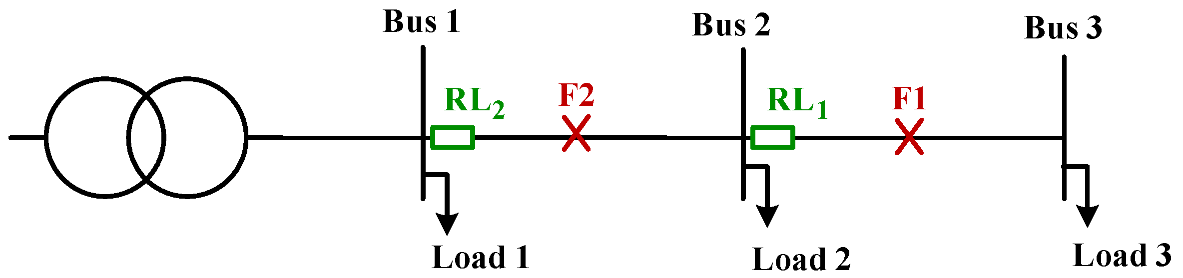
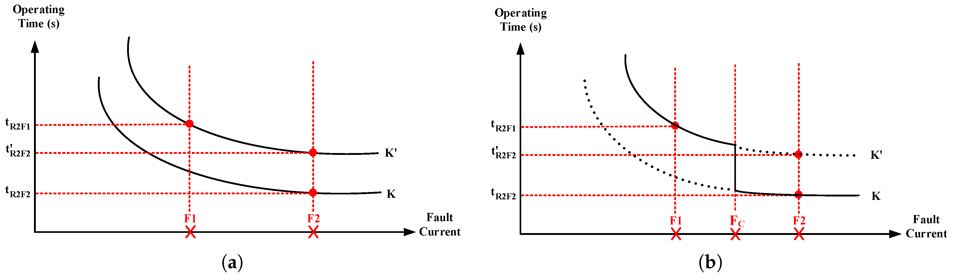
Figure 2 visualizes a simple radial line equipped with two relays, namely and . Considering this line, is the primary relay and it should be operated at the least possible time in case of fault F2. Assuming that is only responsible for the primary operation and is operated utilizing characteristics shown by K in Figure 3a, the operation time for F2 can be obtained as . However, considering the conventional protection case, it has to react also for F1 as a backup relay for . As a consequence, has to be operated in a coordinated manner with according to the characteristics denoted by in Figure 3a. In this case, set values of are calculated taking into account the operation time of for F1 () and coordination time interval (CTI). The new characteristic, , leads to a higher operation time of for F2, which is denoted by in Figure 3a.
In order to deal with the aforementioned problem of conventional protection approach, a double characteristic protection scheme is developed based on the programmable attribute of digital relays considered in this study. The main aim of the recommended scheme is to operate the relays with two distinct characteristics for ensuring protection coordination. One of these characteristics is responsible for primary, while the other is responsible for backup operation. It should be noted that a critical fault current level is utilized in order to switch between the characteristics during operation. The designed protection scheme is sketched in Figure 3b. As seen, the relay uses two characteristics K and . The relay uses backup characteristic for the operation against the faults lower than the predefined critical fault current () in order to be coordinated with for F1, while primary characteristic is utilized for the faults higher than . It is worth underlining that may be considered as a range instead of an exact point so as to prevent non-selective operation due to changing fault currents during transients.
3. Optimization of Protection Coordination
In this section, the formulation of the protection coordination problem and the considered cases are first described in detail. Then, the solution technique applied to solve the optimization problem is elaborated.
3.1. Problem Formulation and Evaluated Cases
In this study, the protection coordination problem is formulated as an optimization problem the objective of which is to minimize the total operating time of the relays in the system subject to CTI and relay settings constraints. The main aim of this problem is to find proper relay settings that decrease the operating time of primary and backup relays, for four types of faults, namely single-line-to-ground (SLG), double-line-to-ground (DLG), line-to-line (LL), and three phase faults. The objective function can be written as follows:
where
- T denotes the total operating time of the relays,
- Y symbolizes the total number of the relays while i is the relay indicator,
- G represents the total number of the faults considered while j is the fault type indicator,
- states the total number of the backup relays for each primary relay,
- and express the primary and backup operating time of i th relay for fault type j, respectively.
In this paper, three cases are considered and depending on the cases, different constraints are utilized in the model. In Case 1, it is assumed that all the protective devices are equipped with the IEC standard characteristic. As a consequence, and that are in the IEC standard equation considered as variables to be optimized. However, in Cases 2 and 3, the relays are assumed to utilize the proposed characteristic. Thus, A, B, and C are regarded as variables to adjust relay characteristics in these cases. The difference between Cases 2 and 3 is that each relay is operated using only one set of A, B, and C variables in Case 2, whereas each relay has two different sets of A, B, and C variables that are utilized separately for primary and backup operation in Case 3.
One of the vital parts of the optimization model of the protection coordination problem is the set of constraints. In this study, there are two common constraints considered for each case in the optimization problem. The first constraint, which enforces that the required time delay for the backup relay in order not to operate earlier than the primary relay for the fault j, is given by Equation (5). By doing so, the selective operation of protection system is ensured. In this constraint, denotes the primary operation time of i-th relay for fault type j, while represents the backup operation time of r-th relay, which is in coordination with the i-th relay assigned to the same fault. It is noteworthy that the CTI value is taken as 0.3 s in this paper, in accordance with the general application in the literature. The second constraint, which ensures that pickup current setting () of i-th relay should be greater than the maximum value between the minimum allowed set value () and the maximum load current value seen by relay (), is given by (6). At the same time, has to be lower than the minimum value between the maximum allowed set value () and the minimum fault current seen by the relay (). It is worth noting that the minimum and maximum values for are taken as 0 and 5 for each relay, respectively:
In Case 1, bounds for variable are provided by Equation (7). This is also the last constraint for the formulation of the problem in Case 1. The upper and lower bounds of values are considered as 0.05 and 1, respectively:
Constraints ((8)–(10)) are only taken into account for Cases 2 and 3. For these cases, three variables are also introduced in addition to , while is neglected since it is not used in the proposed characteristic. Constraints ((8)–(10)) limit A, B, and C variables for each relay, respectively. By introducing these bounds for variables in the proposed equation, the problem formulation is completed for Case 2:
The formulation of the problem is modified by introducing three constraints so as to reflect operation of the double characteristic in Case 3. Constraints ((11)–(13)) are used only for this case in order to provide limits to the decision variables that are used to adjust the second characteristic. It is worth noting that the second characteristic is assumed to be used for the backup operation. Additional bounds are as follows:
The limit values for the variables A, B, and C are determined using the lowest and the highest possible TDS limits of the IEC standard characteristic. In order to keep the proposed characteristic within roughly the same region as the IEC standard characteristic, the minimum values are taken as 1, 0 and 0 for A, B, and C, respectively, while the maximum values are taken as 1.25, 1, and 0.5.
3.2. Solution Method
The constructed optimization model of the protection coordination problem is solved using a genetic algorithm (GA) approach in this study. GA, which is one of the most popular population-based algorithms used in order to deal with nonlinear problems, is chosen as the solution method because of the nonlinear structure of both the IEC standard and the proposed equation. The GA is coded using MATLAB software (2017a, Mathworks, Natick, MA, USA). The GA involves selection, crossover, and mutation operators as well as fitness function [25]. The operators of GA are coded without any change except for the fitness function, which is modified in order to reflect the total operating time of the relays. Furthermore, chromosomes that constitute the population are encoded using binary-coding approach. It should be emphasized that in this study, GA is utilized instead of building a totally new computational method, and, therefore, proposing a new solution method is out of scope of this study.
In each of the three different cases that are considered in this study, a different chromosome structure is used because of the different number of variables involved. The chromosome structure used in Case 1 can be seen in Figure 4a. As shown in the Figure 4a, there are two different variables per relay and each chromosome carries information about 32 variables in total. For Case 2, the number of variables per relay increased to four and, therefore, a larger chromosome structure is used in this case. Figure 4b visualizes the utilized chromosome structure for Case 2. As it can be seen, one chromosome carries the data of 64 variables, which are used to adjust the proposed characteristic in an optimal way so as to ensure relay coordination. The chromosome structure for the final case is depicted in Figure 4c. In this case, the number of variables per relay is seven since a double characteristic is used; however, only 33 variables are added to the chromosome structure. The reason for this is that some relays are not assigned as backup relays and do not need a double characteristic. In this case, 11 relays should provide backup protection, which means each of these relays needs a second set of A, B, and C in order to construct a backup curve. It should also be underlined that the number of the variable does not change since both characteristics should behave asymptotically at the current set point and therefore only one variable per relay is utilized. It is worth emphasizing that subscript g denotes the total number of backup protection relays in Figure 4c.
The population size is determined using the ten times rule according to [26]. Thus, population sizes are selected as 10,000 for Case 1, and as 40,000 for Cases 2 and 3. In addition, the initial population is generated randomly in each simulation using an episodic approach in which values that violate defined ranges are eliminated during the population generation. Moreover, the probability of mutation is taken as 0.05.
4. Results and Discussion
This section is devoted to presenting details of the test system under study, the considered scenarios, and simulation results.
4.1. Test System and Scenarios
The IEEE 14-bus system is used in order to test the proposed protection scheme. The single line diagram of the IEEE 14-bus system can be seen in Figure 5 [27]. The system consists of two parts that are operated at different voltage levels and that are connected via two 60-MVA 132-kV/33-kV transformers and one three winding transformer. Moreover, the power is supplied by two generators that are located on the HV side. Apart from these two generators, the system also includes three synchronous condensers that supply reactive power to the system.
In this study, sixteen protection relays are assumed to be placed on the MV side of the system as shown in Figure 5. The protection coordination studies are carried out considering that the faults occur at the mid-point of each line from L1 to L8. It is worth mentioning again that four different fault types, namely SLG, DLG, LL, and three-phase faults, are taken into account. Primary and backup relays were assigned to each fault except for the ones that require backup protection from outside of the MV system. For example, R12 is the primary relay while R10 is the backup relay for any possible fault on line L6. Similarly, on the other side of the line, R13 is assigned as the primary relay and is backed up by R15. However, R4 is operated as the backup for R2 in case of a fault on line L1 while R1 is the only relay that is responsible for the same fault. The reason for not assigning a backup relay on this occasion is that even if R5 and R16 are assigned as backup relays for R1 and they operated when R1 fails to operate, the fault current can still be supplied from bus 6. Thus, set parameters of R1 should be calculated not only considering R5 and R16 as backup relays but also the other protective equipment that are placed beyond bus 6.
Current transformers also play a critical role in the protection coordination studies. The ratios of current transformers used in this study are given in Table 1 [28]. It should be emphasized that some of the lower bounds of variables are taken as zero since DOCRs are utilized and, therefore, in particular scenarios, some of the relays do not sense any load current in directions which they are liable for.
Fifteen scenarios are generated in order to observe the proposed protection approach under different DG penetration conditions in terms of size and location. Table 2 provides a synopsis of the constructed scenarios. For instance, a 3.3-MVA DG unit is connected to bus 10 in scenario 2. Furthermore, integrated DGs to the buses are regarded as having an identical size for scenarios 3, 4, 5, and 6, which is also denoted by “*” in the Table. It should be noted that all the DGs for every scenario are considered having synchronous generators that are capable of providing energy at 480 V level with a 9.67% transient reactance and that DGs transfer energy utilizing step-up transformers whose transient reactances are 5%. It is worth noting that all load flow and short circuit calculations are carried out by using DIgSILENT/PowerFactory software (15.2, DIgSILENT GmbH, Gomaringen, Germany) [29].
4.2. Results
The constructed optimization problem in Section 3 is solved by taking into account the IEC standard characteristic as well as the proposed characteristic. It should be noted that the IEC normal standard characteristic with and is used in order to carry out comparison studies.
Table 3 encapsulates the calculated set values of directional OCRs using GA. In Table 3, Case 1 presents the set values of A and B used in the IEC standard equation while Cases 2 and 3 give the set values of the proposed characteristic. It can be seen in Table 3 that none of the results violate the constraints. Table 4 summarizes the operation time of the each relay against each fault type considered in the study. For the sake of clarity, Table 4 presents only the results for Scenario 6. It is worth noticing that the results of proposed characteristic in Table 4 are obtained considering double characteristic operation (Case 3). The results of the total operation time of the relays for each scenario and each case considered in the study are presented in Table 5. Moreover, percentage reductions in time for Cases 2 and 3 are also indicated in Table 5 by comparing both cases to Case 1.
4.3. Discussion
Considering the operation time of the relays presented individually in Table 4, a decrease is achieved in each individual relay operation time for each fault type by using the proposed protection scheme while maintaining the proper CTI between every primary and backup relay pair. It can be seen in Table 5 that the lower total operation time of the relays can be obtained by utilizing the proposed characteristic in Cases 2 and 3 for each scenario with respect to Case 1. For instance, the operation time of the relays is decreased by 26.43% in Case 2 for scenario 6. Further reduction in operation time of the relays as 62.21% compared to Case 1 can also be provided by using the proposed protection scheme for the same scenario. A significant reduction in primary operation time of the relays is achieved by utilizing the double characteristic. For instance, in case of a fault in the line L4, the primary operation time of R7 is 0.70 s for conventional characteristic, while it is 0.01 s for the proposed characteristic. In addition, the results also show that DG affects the protection coordination, nonetheless, the relation between DG location, size, and the operation time of the relays cannot be clearly identified by the obtained results.
5. Conclusions
Considering the integration of distributed generation (DG) units to a meshed distribution system, this paper presents a non-standard relay characteristic that utilizes both current and voltage measurements, and a protection scheme in which relays are operated with the double characteristic consisting of distinct relay characteristics for primary and backup operation. In a classical protection approach, precaution options against the effect of DG are limited because the standard characteristic depends only on the current measurement. Thus, based on the programmable structure of digital relays, the propounded characteristic and protection scheme are devised as an alternative to the classical approach. The proposed method is tested by a simulation study in which connections of synchronous based DG units into a meshed distribution system are considered. The protection coordination problem is formulated as an optimization problem. In order to solve this problem, GA is executed after calculating the fault currents of single-line-to-ground, double-line-to-ground, line-to-line, and three-phase faults occurring in the middle of each line. The results reveal that the protection coordination is achieved by using the proposed protection scheme even for different locations and capacities of DG units. Apart from providing reliable protection, further enhancements in the total operation time of the relays can be provided by using both the proposed characteristic and protection scheme. It should be also noted that using a double characteristic for relays results in a higher decrease in total operation time of the relays. This study considers the construction of one single characteristic for all the fault types. Development of distinct characteristics for each type of fault for operating the relay in an adaptive way will be considered in a future study to be conducted by the authors.
Author Contributions
H.C.K. conceived and designed the simulation models in DIgSILENT/PowerFactory and coded the optimization algorithm in MATLAB; H.C.K. and H.A. performed the simulations in MATLAB; H.A. and İ.Ş. performed the simulations in DIgSILENT/PowerFactory; İ.Ş. also contributed by providing support for organization of graphics and general structure of the paper; H.C.K. analyzed the data and wrote the paper; B.K. contributed by supervising the research; N.G.P. contributed by overall technical suggestions through the research steps and also contributed to the writing of the final research paper.
Acknowledgments
Hasan Can Kılıçkıran would like to acknowledge the support of TUBITAK (The Scientific and Technological Research Council of Turkey) BIDEB 2214-A under the project code 1059B141601327.
Conflicts of Interest
The authors declare no conflict of interest.
References
- Anderson, P.M. Power System Protection; Wiley: New York, NY, USA, 1998. [Google Scholar]
- Lan, T.; Li, Y.; Duan, X.; Zhu, J. Simplified Analytic Approach of Pole-to-Pole Faults in MMC-HVDC for AC System Backup Protection Setting Calculation. Energies 2018, 11, 264. [Google Scholar] [CrossRef]
- Jing, L.; Son, D.H.; Kang, S.H.; Nam, S.R. A novel protection method for single line-to-ground faults in ungrounded low-inertia microgrids. Energies 2016, 9, 459. [Google Scholar] [CrossRef]
- Norshahrani, M.; Mokhlis, H.; Abu Bakar, A.H.; Jamian, J.J.; Sukumar, S. Progress on Protection Strategies to Mitigate the Impact of Renewable Distributed Generation on Distribution Systems. Energies 2017, 10, 1864. [Google Scholar] [CrossRef]
- Ok, Y.; Lee, J.; Choi, J. Analysis and solution for operations of overcurrent relay in wind power system. Energies 2016, 9, 458. [Google Scholar] [CrossRef]
- Abdel-Salam, M.; Kamel, R.; Sayed, K.; Khalaf, M. Design and implementation of a multifunction DSP-based-numerical relay. Electr. Power Syst. Res. 2017, 143, 32–43. [Google Scholar] [CrossRef]
- Phadke, A.G.; Thorp, J.S. Computer Relaying for Power Systems; John Wiley & Sons: Hoboken, NJ, USA, 2009. [Google Scholar]
- Brahma, S.M.; Girgis, A.A. Development of adaptive protection scheme for distribution systems with high penetration of distributed generation. IEEE Trans. Power Deliv. 2004, 19, 56–63. [Google Scholar] [CrossRef]
- Ma, J.; Wang, X.; Zhang, Y.; Yang, Q.; Phadke, A. A novel adaptive current protection scheme for distribution systems with distributed generation. Int. J. Electr. Power Energy Syst. 2012, 43, 1460–1466. [Google Scholar] [CrossRef]
- El-Khattam, W.; Sidhu, T.S. Restoration of directional overcurrent relay coordination in distributed generation systems utilizing fault current limiter. IEEE Trans. Power Deliv. 2008, 23, 576–585. [Google Scholar] [CrossRef]
- Soria, O.A.; Enríquez, A.C.; Guajardo, L.T. Overcurrent relay with unconventional curves and its application in industrial power systems. Electr. Power Syst. Res. 2014, 110, 113–121. [Google Scholar] [CrossRef]
- Saleh, K.A.; Zeineldin, H.; Al-Hinai, A.; El-Saadany, E.F. Optimal coordination of directional overcurrent relays using a new time–current–voltage characteristic. IEEE Trans. Power Deliv. 2015, 30, 537–544. [Google Scholar] [CrossRef]
- Saleh, K.A.; El Moursi, M.S.; Zeineldin, H.H. A new protection scheme considering fault ride through requirements for transmission level interconnected wind parks. IEEE Trans. Ind. Inform. 2015, 11, 1324–1333. [Google Scholar] [CrossRef]
- Dewadasa, M.; Ghosh, A.; Ledwich, G. Fold back current control and admittance protection scheme for a distribution network containing distributed generators. IET Gene. Transm. Distrib. 2010, 4, 952–962. [Google Scholar] [CrossRef]
- Dewadasa, M.; Ghosh, A.; Ledwich, G. An inverse time admittance relay for fault detection in distribution networks containing DGs. In Proceedings of the TENCON 2009—2009 IEEE Region 10 Conference, Singapore, 23–26 January 2009; pp. 1–6. [Google Scholar]
- Yazdaninejadi, A.; Jannati, J.; Farsadi, M. A New Formulation for Coordination of Directional Overcurrent Relays in Interconnected Networks for Better Miscoordination Suppression. Trans. Electr. Electron. Mater. 2017, 18, 169–175. [Google Scholar]
- Alkaran, D.S.; Vatani, M.R.; Sanjari, M.J.; Gharehpetian, G.B.; Naderi, M.S. Optimal Overcurrent Relay Coordination in Interconnected Networks by Using Fuzzy-Based GA Method. IEEE Trans. Smart Grid 2016. [Google Scholar] [CrossRef]
- Ahmadi, S.; Karami, H.; Sanjari, M.; Tarimoradi, H.; Gharehpetian, G. Application of hyper-spherical search algorithm for optimal coordination of overcurrent relays considering different relay characteristics. Int. J. Electr. Power Energy Syst. 2016, 83, 443–449. [Google Scholar] [CrossRef]
- Negrão, D.L.; Vieira, J.C. The Local Fit Method for Coordinating Directional Overcurrent Relays. IEEE Trans. Power Deliv. 2016, 31, 1464–1472. [Google Scholar] [CrossRef]
- Karegar, H.K.; Aghdam, T.S. Relay Curve Selection Approach for Microgrid Optimal Protection. Int. J. Renew. Energy Res. 2017, 7, 636–642. [Google Scholar]
- Keil, T.; Jager, J. Advanced coordination method for overcurrent protection relays using nonstandard tripping characteristics. IEEE Trans. Power Deliv. 2008, 23, 52–57. [Google Scholar] [CrossRef]
- Ojaghi, M.; Ghahremani, R. Piece–wise Linear Characteristic for Coordinating Numerical Overcurrent Relays. IEEE Trans. Power Deliv. 2017, 32, 145–151. [Google Scholar] [CrossRef]
- IEC. Electrical Relays-Part 3: Single Input Energizing Quantity Measuring Relays with Dependent or Independent Time, 60255-3; IEC: Geneva, Switzerland, 1989. [Google Scholar]
- IEEE. Standard Inverse-Time Characteristic Equations for Overcurrent Relays, Std C37.112-1996; IEEE: Minneapolis, MN, USA, 1996. [Google Scholar]
- Goldberg, D.E.; Holland, J.H. Genetic algorithms and machine learning. Mach. Learn. 1988, 3, 95–99. [Google Scholar] [CrossRef]
- Storn, R. On the usage of differential evolution for function optimization. In Proceedings of the 1996 Biennial Conference of the North American NAFIPS Fuzzy Information Processing Society, Berkeley, CA, USA, 19–22 June 1996; pp. 519–523. [Google Scholar]
- University of Washington. Power Systems Test Case Archive. 1993. Available online: https://www2.ee.washington.edu/research/pstca/ (accessed on 5 February 2018).
- Talaat, H.E.A.; Abdelaziz, A.Y.; Nosseir, A.I.; Hajjar, A.A. Optimal coordination of overcurrent relays by linear programming: An enhanced problem formulation. In Proceedings of the 1999 Arab Countries IEEE 3rd CIGRE Regional Conference, Douha, Qatar, 25–27 May 1999. [Google Scholar]
- DIgSILENT GmbH. DIgSILENT/PowerFactory Software. Available online: https://www.digsilent.de/en/ (accessed on 5 March 2018).
Figure 1.
Illustration of the proposed characteristic for A = 1.1, B = 0.06, and C = 0.1, in comparison with the IEC normal inverse and the IEEE moderately inverse standard characteristics for TDS = 1.
Figure 1.
Illustration of the proposed characteristic for A = 1.1, B = 0.06, and C = 0.1, in comparison with the IEC normal inverse and the IEEE moderately inverse standard characteristics for TDS = 1.
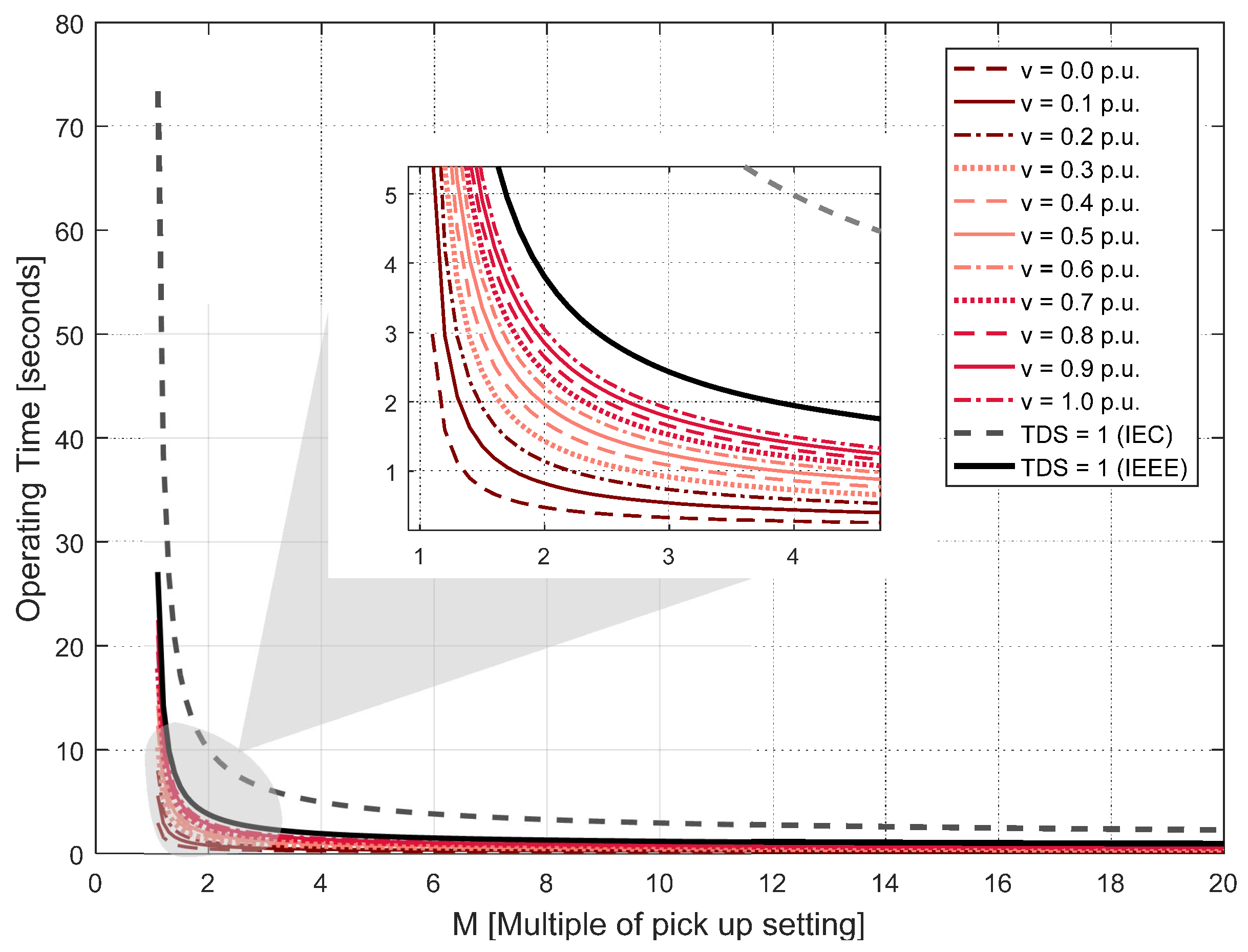
Figure 2.
A simple radial system.

Figure 3.
Protection schemes (a) basic traditional coordination; (b) proposed double relay characteristic.
Figure 3.
Protection schemes (a) basic traditional coordination; (b) proposed double relay characteristic.

Figure 4.
Illustration of chromosome structures (a) chromosome structure used in Case 1; (b) chromosome structure used in Case 2; (c) chromosome structure used in Case 3.
Figure 4.
Illustration of chromosome structures (a) chromosome structure used in Case 1; (b) chromosome structure used in Case 2; (c) chromosome structure used in Case 3.

Figure 5.
The IEEE 14-Bus System under study [27].
Figure 5.
The IEEE 14-Bus System under study [27].


Table 1.
Current transformer ratios.
| Relay Name | R1 | R2 | R3 | R4 | R5 | R6 | R7 | R8 |
| Current Tr. Ratio | 400/5 | 100/5 | 200/5 | 300/5 | 100/5 | 300/5 | 200/5 | 100/5 |
| Relay Name | R9 | R10 | R11 | R12 | R13 | R14 | R15 | R16 |
| Current Tr. Ratio | 400/5 | 300/5 | 100/5 | 300/5 | 300/5 | 200/5 | 400/5 | 400/5 |
Table 2.
Considered scenarios in simulation.
| Scenarios | 1 | 2 | 3 | 4 | 5 | 6 | 7 | 8 | 9 | 10 | 11 | 12 | 13 | 14 | 15 |
| Connection Bus(es) | - | 10 | 10,11 | 10,11,12 | 10,11,12,13 | 10,11,12,13,14 | 11 | 11 | 11 | 13 | 13 | 13 | 14 | 14 | 14 |
| DG Size(s) | 3.3 | 3.3* | 3.3* | 3.3* | 3.3* | 3.3* | 3.3 | 5.5 | 9.9 | 3.3 | 5.5 | 9.9 | 3.3 | 5.5 | 9.9 |
Table 3.
Set values calculated using a genetic algorithm.
| Case | Variable | Relay Name | |||||||||||||||
|---|---|---|---|---|---|---|---|---|---|---|---|---|---|---|---|---|---|
| R1 | R2 | R3 | R4 | R5 | R6 | R7 | R8 | R9 | R10 | R11 | R12 | R13 | R14 | R15 | R16 | ||
| 1 | Ip (A) | 3.48 | 2.21 | 2.48 | 1.35 | 1.33 | 2.06 | 2.79 | 1.96 | 4.60 | 3.64 | 0.26 | 3.93 | 3.68 | 1.82 | 3.23 | 4.83 |
| TDS | 0.72 | 0.06 | 0.30 | 0.27 | 0.09 | 0.29 | 0.92 | 0.22 | 0.90 | 0.84 | 0.83 | 0.63 | 0.59 | 0.25 | 0.95 | 0.32 | |
| 2 | Ip (A) | 3.66 | 4.20 | 1.76 | 2.83 | 0.33 | 2.77 | 0.58 | 1.71 | 2.19 | 3.00 | 2.86 | 2.74 | 3.69 | 1.78 | 2.92 | 3.10 |
| A | 1.07 | 1.01 | 1.03 | 1.04 | 1.01 | 1.00 | 1.08 | 1.04 | 1.02 | 1.06 | 1.06 | 1.02 | 1.09 | 1.02 | 1.07 | 1.01 | |
| B | 0.11 | 0.75 | 0.06 | 0.81 | 0.61 | 0.39 | 0.12 | 0.54 | 0.07 | 0.08 | 0.45 | 0.15 | 0.46 | 0.93 | 0.21 | 0.12 | |
| C | 0.31 | 0.03 | 0.02 | 0.36 | 0.12 | 0.40 | 0.34 | 0.13 | 0.29 | 0.38 | 0.13 | 0.13 | 0.40 | 0.14 | 0.48 | 0.29 | |
| 3 | Ip (A) | 1.61 | 3.53 | 0.95 | 3.11 | 0.66 | 1.69 | 0.59 | 0.69 | 1.68 | 3.61 | 2.17 | 1.11 | 4.59 | 1.15 | 4.55 | 3.62 |
| A | 1.02 | 1.08 | 1.03 | 1.09 | 1.03 | 1.07 | 1.04 | 1.00 | 1.07 | 1.02 | 1.06 | 1.01 | 1.03 | 1.09 | 1.08 | 1.02 | |
| Ab | 1.03 | 1.01 | 1.02 | 1.03 | 1.01 | 1.07 | 1.10 | 1.02 | 1.05 | 1.04 | 1.00 | ||||||
| B | 0.90 | 0.64 | 0.91 | 0.88 | 0.81 | 0.29 | 0.43 | 0.62 | 0.71 | 0.92 | 0.96 | 0.17 | 0.50 | 0.64 | 0.48 | 0.76 | |
| Bb | 0.17 | 0.06 | 0.44 | 0.46 | 0.09 | 0.20 | 0.76 | 0.11 | 0.11 | 0.14 | 0.15 | ||||||
| C | 0.05 | 0.04 | 0.34 | 0.05 | 0.12 | 0.25 | 0.02 | 0.08 | 0.25 | 0.08 | 0.32 | 0.03 | 0.09 | 0.06 | 0.13 | 0.19 | |
| Cb | 0.33 | 0.00 | 0.46 | 0.43 | 0.16 | 0.44 | 0.45 | 0.48 | 0.40 | 0.30 | 0.33 | ||||||
Table 4.
Operation time of the relays for single-phase-to-ground, double-phase-to-ground, phase-to-phase, and three-phase faults.
Table 4.
Operation time of the relays for single-phase-to-ground, double-phase-to-ground, phase-to-phase, and three-phase faults.
| Operation Time of Relay(s) against Three Phase Fault (pr = primary, bc = backup) (s) | Operation Time of Relay(s) against Double-Phase-to- Ground Fault (pr = primary, bc = backup) (s) | ||||||||||||
|---|---|---|---|---|---|---|---|---|---|---|---|---|---|
| Fault Location | Conventional Characteristic | Proposed Characteristic | Fault Location | Conventional Characteristic | Proposed Characteristic | ||||||||
| pr | bc1 | bc2 | pr | bc1 | bc2 | pr | bc1 | bc2 | pr | bc1 | bc2 | ||
| L1 | R1: 1.09 | R1: 0.07 | L1 | R1: 1.04 | R1: 0.07 | ||||||||
| R2: 0.05 | R4: 0.36 | R2: 0.21 | R4: 0.54 | R2: 0.05 | R4: 0.35 | R2: 0.21 | R4: 0.55 | ||||||
| L2 | R3: 0.92 | R1: 1.47 | R3: 0.09 | R1: 0.74 | L2 | R3: 0.89 | R1: 1.39 | R3: 0.10 | R1: 0.74 | ||||
| R4: 0.33 | R16: 0.97 | R7: 0.87 | R4: 0.04 | R16: 0.44 | R7: 0.58 | R4: 0.32 | R16: 0.91 | R7: 0.86 | R4: 0.04 | R16: 0.44 | R7: 0.60 | ||
| L3 | R16: 0.68 | R16:0.14 | L3 | R16: 0.63 | R16: 0.14 | ||||||||
| R5: 0.10 | R3: 1.16 | R7: 0.81 | R5: 0.01 | R3: 0.55 | R7: 0.54 | R5: 0.10 | R3: 1.16 | R7: 0.79 | R5: 0.02 | R3: 0.58 | R7: 0.56 | ||
| L4 | R6: 0.50 | R16: 0.98 | R3: 1.28 | R6: 0.07 | R16: 0.48 | R3: 0.65 | L4 | R6: 0.49 | R16: 0.94 | R3: 1.24 | R6: 0.08 | R16: 0.48 | R3: 0.66 |
| R7: 0.70 | R9: 1.93 | R7: 0.01 | R9: 0.73 | R7: 0.68 | R9: 1.85 | R7: 0.01 | R9: 0.74 | ||||||
| L5 | R15: 1.35 | R15: 0.06 | L5 | R15: 1.27 | R15: 0.06 | ||||||||
| R14: 0.30 | R12: 0.73 | R14: 0.01 | R12: 0.41 | R14: 0.29 | R12: 0.72 | R14: 0.02 | R12: 0.44 | ||||||
| L6 | R12: 0.66 | R10: 1.48 | R12: 0.01 | R10: 0.40 | L6 | R12: 0.64 | R10: 1.40 | R12: 0.01 | R10: 0.42 | ||||
| R13: 1.28 | R15: 1.77 | R13: 0.21 | R15: 0.94 | R13: 1.24 | R15: 1.70 | R13: 0.22 | R15: 0.99 | ||||||
| L7 | R10: 1.28 | R10: 0.05 | L7 | R10: 1.18 | R10: 0.05 | ||||||||
| R11: 0.52 | R13: 1.45 | R11: 0.01 | R13: 0.61 | R11: 0.52 | R13: 1.42 | R11: 0.01 | R13: 0.71 | ||||||
| L8 | R8: 0.11 | R6: 0.62 | R8: 0.07 | R6: 0.71 | L8 | R8: 0.10 | R6: 0.61 | R8: 0.07 | R6: 0.73 | ||||
| R9: 1.48 | R9: 0.06 | R9: 1.40 | R9: 0.06 | ||||||||||
| L1 | R1: 1.04 | R1: 0.07 | L1 | R1: 1.14 | R1: 0.08 | ||||||||
| R2: 0.05 | R4: 0.35 | R2: 0.22 | R4: 0.59 | R2: 0.05 | R4: 0.38 | R2: 0.22 | R4: 0.61 | ||||||
| L2 | R3: 0.89 | R1: 1.39 | R3: 0.10 | R1: 0.77 | L2 | R3: 0.95 | R1: 1.55 | R3: 0.11 | R1: 0.80 | ||||
| R4: 0.32 | R16: 0.91 | R7: 0.86 | R4: 0.05 | R16: 0.49 | R7: 0.62 | R4: 0.34 | R16: 1.04 | R7: 0.90 | R4: 0.05 | R16: 0.54 | R7: 0.62 | ||
| L3 | R16: 0.63 | R16: 0.15 | L3 | R16: 0.71 | R16: 0.15 | ||||||||
| R5: 0.10 | R3: 1.15 | R7: 0.69 | R5: 0.02 | R3: 0.64 | R7: 0.59 | R5: 0.10 | R3: 1.31 | R7: 0.84 | R5: 0.02 | R3: 0.66 | R7: 0.59 | ||
| L4 | R6: 0.49 | R16: 0.94 | R3: 1.24 | R6: 0.09 | R16: 0.51 | R3: 0.69 | L4 | R6: 0.52 | R16: 1.05 | R3: 1.34 | R6: 0.09 | R16: 0.57 | R3: 0.71 |
| R7: 0.69 | R9: 1.86 | R7: 0.01 | R9: 0.76 | R7: 0.72 | R9: 2.03 | R7: 0.01 | R9: 0.79 | ||||||
| L5 | R15: 1.27 | R15: 0.06 | L5 | R15: 1.42 | R15: 0.07 | ||||||||
| R14: 0.29 | R12: 0.72 | R14: 0.03 | R12: 0.49 | R14: 0.32 | R12: 0.75 | R14: 0.03 | R12: 0.49 | ||||||
| L6 | R12: 0.64 | R10: 1.40 | R12: 0.01 | R10: 0.46 | L6 | R12: 0.68 | R10: 1.32 | R12: 0.01 | R10: 0.48 | ||||
| R13: 1.24 | R15: 1.70 | R13: 0.23 | R15: 1.08 | R13: 1.34 | R15: 1.89 | R13: 0.24 | R15: 1.16 | ||||||
| L7 | R10: 1.17 | R10: 0.06 | L7 | R10: 1.32 | R10: 0.07 | ||||||||
| R11: 0.52 | R13: 1.42 | R11: 0.01 | R13: 0.93 | R11: 0.54 | R13: 1.52 | R11: 0.01 | R13: 0.95 | ||||||
| L8 | R8: 0.10 | R6: 0.61 | R8: 0.08 | R6: 0.76 | L8 | R8: 0.11 | R6: 0.65 | R8: 0.08 | R6: 0.79 | ||||
| R9: 1.40 | R9: 0.06 | R9: 1.54 | R9: 0.07 | ||||||||||
Table 5.
Total operation time of the relays for all cases and scenarios.
| Case | Pop. Data | Scenario | ||||||||||||||
|---|---|---|---|---|---|---|---|---|---|---|---|---|---|---|---|---|
| 1 | 2 | 3 | 4 | 5 | 6 | 7 | 8 | 9 | 10 | 11 | 12 | 13 | 14 | 15 | ||
| 1 | Mean Value (s) | 103.08 | 133.64 | 111.48 | 113.40 | 121.51 | 112.66 | 199.00 | 148.87 | 127.26 | 133.38 | 121.55 | 155.09 | 112.76 | 106.75 | 107.24 |
| Variance (s) | 0.78 | 3.78 | 3.50 | 2.72 | 1.32 | 2.38 | 5.21 | 2.31 | 6.00 | 3.46 | 6.19 | 4.92 | 2.99 | 4.09 | 2.11 | |
| Best Ind. (s) | 101.41 | 127.69 | 105.90 | 108.30 | 118.39 | 108.27 | 111.02 | 143.23 | 119.54 | 128.96 | 113.58 | 147.40 | 107.48 | 99.73 | 103.25 | |
| 2 | Mean (s) | 86.64 | 85.70 | 75.43 | 76.19 | 80.92 | 83.12 | 75.04 | 81.74 | 80.99 | 92.73 | 89.58 | 90.47 | 91.27 | 86.40 | 81.80 |
| Variance (s) | 2.81 | 1.59 | 0.88 | 1.34 | 1.41 | 1.09 | 3.00 | 1.57 | 0.80 | 3.16 | 1.83 | 0.91 | 1.21 | 1.59 | 1.23 | |
| Best Ind. (s) | 80.19 | 81.11 | 71.52 | 72.50 | 76.60 | 79.65 | 70.39 | 77.45 | 75.55 | 86.52 | 85.25 | 87.08 | 87.71 | 82.28 | 76.84 | |
| Decrese in T (%) | 20.92 | 36.48 | 32.46 | 33.06 | 35.30 | 26.43 | 36.60 | 45.93 | 36.80 | 32.91 | 24.94 | 40.93 | 18.40 | 17.50 | 25.58 | |
| 3 | Mean (s) | 49.30 | 48.91 | 44.78 | 48.12 | 43.62 | 44.70 | 53.69 | 61.63 | 56.20 | 65.81 | 43.04 | 51.85 | 57.17 | 53.78 | 52.36 |
| Variance (s) | 1.06 | 0.89 | 0.61 | 0.52 | 2.90 | 0.96 | 0.89 | 0.35 | 0.61 | 1.37 | 0.63 | 0.28 | 1.29 | 0.73 | 0.39 | |
| Best Ind. (s) | 46.12 | 45.23 | 42.16 | 45.65 | 40.51 | 40.92 | 50.26 | 59.44 | 53.61 | 61.84 | 40.39 | 50.06 | 52.78 | 50.77 | 50.38 | |
| Decrese in T (%) | 54.52 | 64.58 | 60.19 | 57.85 | 65.78 | 62.21 | 54.73 | 58.50 | 55.15 | 52.05 | 64.44 | 66.04 | 50.89 | 49.09 | 51.21 | |
© 2018 by the authors. Licensee MDPI, Basel, Switzerland. This article is an open access article distributed under the terms and conditions of the Creative Commons Attribution (CC BY) license (http://creativecommons.org/licenses/by/4.0/).
Share and Cite
MDPI and ACS Style
Kılıçkıran, H.C.; Akdemir, H.; Şengör, İ.; Kekezoğlu, B.; Paterakis, N.G. A Non-Standard Characteristic Based Protection Scheme for Distribution Networks. Energies 2018, 11, 1241. https://doi.org/10.3390/en11051241
AMA Style
Kılıçkıran HC, Akdemir H, Şengör İ, Kekezoğlu B, Paterakis NG. A Non-Standard Characteristic Based Protection Scheme for Distribution Networks. Energies. 2018; 11(5):1241. https://doi.org/10.3390/en11051241
Chicago/Turabian StyleKılıçkıran, Hasan Can, Hüseyin Akdemir, İbrahim Şengör, Bedri Kekezoğlu, and Nikolaos G. Paterakis. 2018. "A Non-Standard Characteristic Based Protection Scheme for Distribution Networks" Energies 11, no. 5: 1241. https://doi.org/10.3390/en11051241
Note that from the first issue of 2016, this journal uses article numbers instead of page numbers. See further details here.