Article

Study on Heat Utilization in an Attached Sunspace in a House with a Central Heating, Ventilation, and Air Conditioning System

1
Department of Architecture, The University of Kitakyushu, Kitakyushu 808-0135, Japan
2
School of Architecture and Civil Engineering, Chengdu University, Chengdu 610106, China
3
Department of Architecture and Urban Design, Ritsumeikan University, Kyoto 603-8577, Japan
4
Tohata Architects & Engineers, Osaka 541-0043, Japan
5
Faculty of Engineering, Shonan Institute of Technology, Kanagawa 251-0046, Japan
6
Department of Architecture and Urban Design, Kyushu University, Fukuoka 812-0053, Japan
7
School of Environmental and Municipal Engineering, Jilin Jianzhu University, Changchun 130118, China
*
Author to whom correspondence should be addressed.
Energies 2018, 11(5), 1192; https://doi.org/10.3390/en11051192
Submission received: 11 March 2018 / Revised: 3 May 2018 / Accepted: 5 May 2018 / Published: 8 May 2018

Abstract

:
Based on numerical simulations, the heating load reduction effect of an attached sunspace in winter was determined, and the effective heat utilization method and sunspace design were explored. In this paper, we studied the heating load reduction effect using heat from the sunspace and temperature fluctuation of each room at the time of heat use from the sunspace (sending air from the sunspace to the heating, ventilation, and air conditioning (HVAC) machine room and taking the air to the adjacent rooms). In the case of the all-day HVAC system, it was confirmed that a larger capacity of sunspace and not sending air from the sunspace to the adjacent room demonstrated a better heating-load reduction effect. Compared with Model Iw (a house with a window on the exterior of the sunspace opened to external air), Model I (a house with an attached sunspace on the second floor) could save approximately 41% of the total energy. Model II (a house with the attached sunspace both on the first and second floors) could save approximately 84% of the total energy. Sending heat from the sunspace to the adjacent room led to temperature increases in the adjacent rooms. However, if the construction plan is to have the sunspace only on the second floor, the house should be carefully designed, for example, by placing a living room on the second floor.

1. Introduction

Building energy consumption accounts for a great part of regional and global energy requirements. Japan’s buildings consume more than 30% of the country’s energy consumption [1]. In recent years, standards for energy saving have been reviewed as the awareness of energy and global warming grows. Accordingly, measures for improving thermal insulation, energy generation, and efficient energy usage in houses are considered important. Their purpose is to realize a 10% increase in the ratio of renewable energy per primary energy supply by 2020, through promoting solar energy and solar light [1]. One of the most popular methods of using solar energy is the attached sunspace, which expands the usable area of the adjacent room. Sunspaces absorb solar energy and transmit some of the absorbed energy into the building by conduction and the rest by convection [2].
Many scholars studied various components to help improve the efficiency of sunspaces, such as glaze types, glazed area, the dimension and form of sunspaces, shading devices, ventilation, orientation, and the storage wall’s materials. Bakos and Tsagas [3] investigated the energy and economic performance of a conventional dwelling with an attached sunspace located in northern Greece. The results showed that the optimum heat-gathering area was approximately 13.75 m2, which can save 18% of the annual thermal energy. Mihalakakou [4] studied the cooling/heating ability of buildings equipped with sunspaces in Milan, Dublin, Athens, and Florence. The results showed that sunspaces can reduce thermal heating energy in winter, but cause severe overheating problems in summer. The problem of overheating can be solved by using three passive cooling technologies (shading devices, night ventilation, and buried pipes). Lu et al. [5] studied the energy consumption of a building with a phase change material (PCM) wall attached with a sunspace and a PCM radiant floor system. The results showed that in the active control phase, the investigational room energy saving rate was 54.27% compared to the traditional room. In the passive energy-storage phase, the traditional room temperature was 7.15 °C lower than that of the investigational room. Ulpiani et al. [6] carried out a numerical and experimental study on the energy performance of nearly zero energy buildings with three different sunspace configurations (convective double-glazed, irradiative double-glazed, and irradiative single-glazed). The results showed that convective double-glazed has the best energy performance. Asdrubali et al. [7] used two stationary procedures (EN ISO 13790 and Method 5000) and a dynamic simulation tool (TRNSYS) to assess the effect of a sunspace on a building’s energy balance. They concluded that the building energy demand was reduced by around 20% and all methods were in good agreement with actual energy consumption data. Chiesa et al. [8] presented a study on the potential applicability of attached sunspaces in 50 locations (southern and central Europe) for heating seasons. They concluded that sunspace use in uninsulated or highly insulated buildings can reduce heating energy. The performance of sunspaces on adjacent rooms was not affected by increasing the internal mass capacity of the walls. Babaee et al. [2] investigated the optimum design for passive heating of a sunspace in an apartment block in a cold climate (Tabriz, Iran) based on six main parameters: prevention of overheating by ventilation and shading, the dimension and form of the sunspace, common wall, glazing materials, sunspace orientation, and glazed surfaces. The results showed that the optimum sunspace design can reduce the adjacent room’s heating energy by up to 46% compared to rooms without sunspaces. Bastien et al. [9] presented a methodology for sizing passive thermal energy storage (TES) systems in six different configurations of greenhouses. They concluded that the thermal mass on both the floor and the wall can increase the highest minimum operative temperature by up to 7 °C. Rempel et al. [10] investigated a series of field-proven sunspace models in the Pacific Northwest to quantify the limits of traditional thermal mass design in the area, and to expose the proper parameters concerning the ground configuration and size of floor-based thermal masses. They concluded that the thermal mass must be fully isolated from moist soils, the traditional rules greatly over-size thermal masses for the West Coast Marine climate, and the optimum mass design depends fundamentally on a space’s thermal design priorities. They also used the EnergyPlus software to investigate the energy performance of four Oregon sunspaces. The results showed that more than half of the total energy entering sunspaces originated as diffuse solar radiation and that 60%–70% of the total energy was transmitted through the shallow-pitched roof glazing [11]. Monge-Barrio and Sánchez-Ostiz [12] studied the energy performance and optimum sunspace design for different climatic zones in Spain. The results showed that even in extreme conditions, the attached sunspaces had good thermal behavior in summer as long as they were properly designed and used. Owrak et al. [13] used the EnergyPlus software to investigate the thermal performance of a room attached with a sunspace. They concluded that the sunspace along with the proposed heat storage system can reduce energy costs by up to 87%. Ignjatović et al. [14] studied the energy performance of a typical residence attached with a sunspace. They concluded that the maximum impact on energy consumption reduction was realized by applying a sunspace with 30% ventilation openings and moderate quality glazing (shading coefficient of glazing is 0.5). Hilliaho et al. [15] used the IDA-ICE 4.6.1 software to study the impact of different types of glazed balconies on buildings’ energy consumption in northern climatic conditions. The results showed that the energy saving in northern climatic conditions was greater than in Central Europe. Zhu et al. [16] carried out a numerical analysis on energy performance for new Yaodong dwellings attached with sunspaces by using the EnergyPlus software. The results showed that the convective heat transfer from the sunspace to the interior can reduce heating energy up to 28%. Sánchez-Ostiz et al. [17] carried out a numerical simulation and experimental study on the performance of an attached sunspace with vertical thermal storage and another with horizontal heat storage. They concluded that a sunspace with heat storage capacity can improve the interior thermal performance of the adjacent room compared to a simple sunspace or a window. Aelenei et al. [18] conducted a numerical study on the energetic performance of a residential building attached with different sunspace configurations in Portugal by using a dynamic simulation code. Results showed that the successful combinations for yearly energy consumption reduction have inner shading devices with high reflectance, natural ventilation of the sunspace, fully integrated sunspace configuration, and south orientation. Tong et al. [19,20] assessed the natural ventilation potential by estimating the natural ventilation hour and used building energy simulation (BES) to calculate the energy-saving potential. The results provided policymakers and architects with valuable guidelines for the effective use of natural ventilation designs that meet local climatic conditions. Oliveti et al. [21] performed a numerical simulation study on the optical and heat efficiency of sunspaces using the dynamic simulation tool DEROB-LTH. They concluded that the heat capacity of the floor and wall had a significant impact on energy consumption. Bataineh and Fayez [22] investigated the thermal energy performance of a living room attached to a sunspace in Amman-Jordan. They concluded that the heating energy consumption decreases by increasing the proportion of glazing surface to the opaque surface.
However, there is no study on the heat utilization in the attached sunspace of a house with a central heating, ventilation, and air conditioning (HVAC) system. New-generation solar thermal houses can provide a comfortable thermal environment and energy efficiency at a high level through a solar heat collection and distribution system based on combining the central HVAC system and a passive/active heating method. The originality of this paper is attained through the mixing mode of the mechanically ventilated sunspace, and the central HVAC for effective heating applied to the structure of an actual house in Japan. The main purpose of this paper was to study the heating load reduction effect of an attached sunspace in a house with an HVAC system based on numerical simulations, and to explore the effective heat utilization method and design of the sunspace in winter.

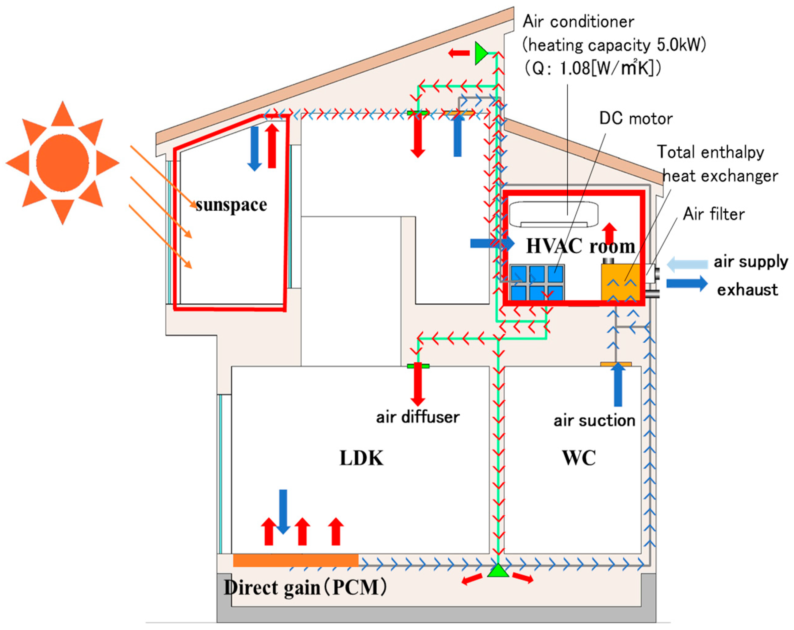
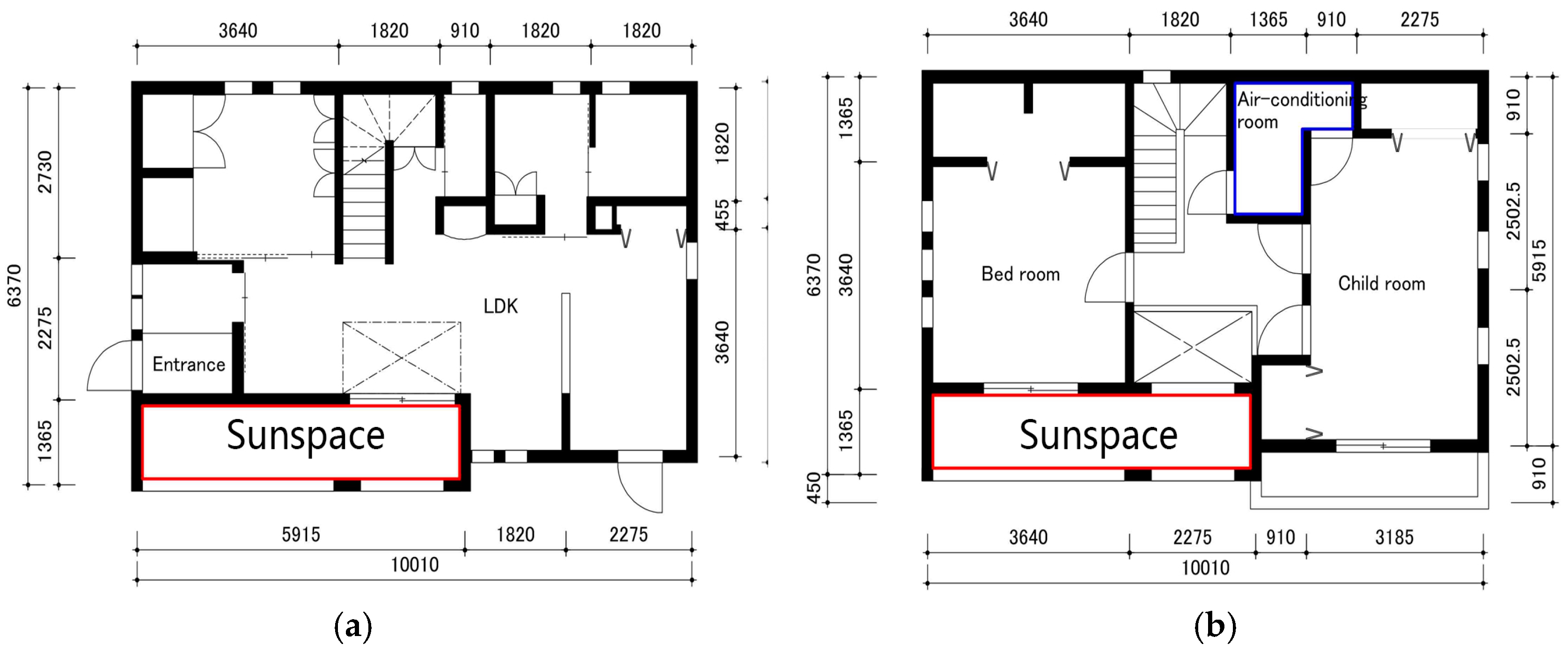
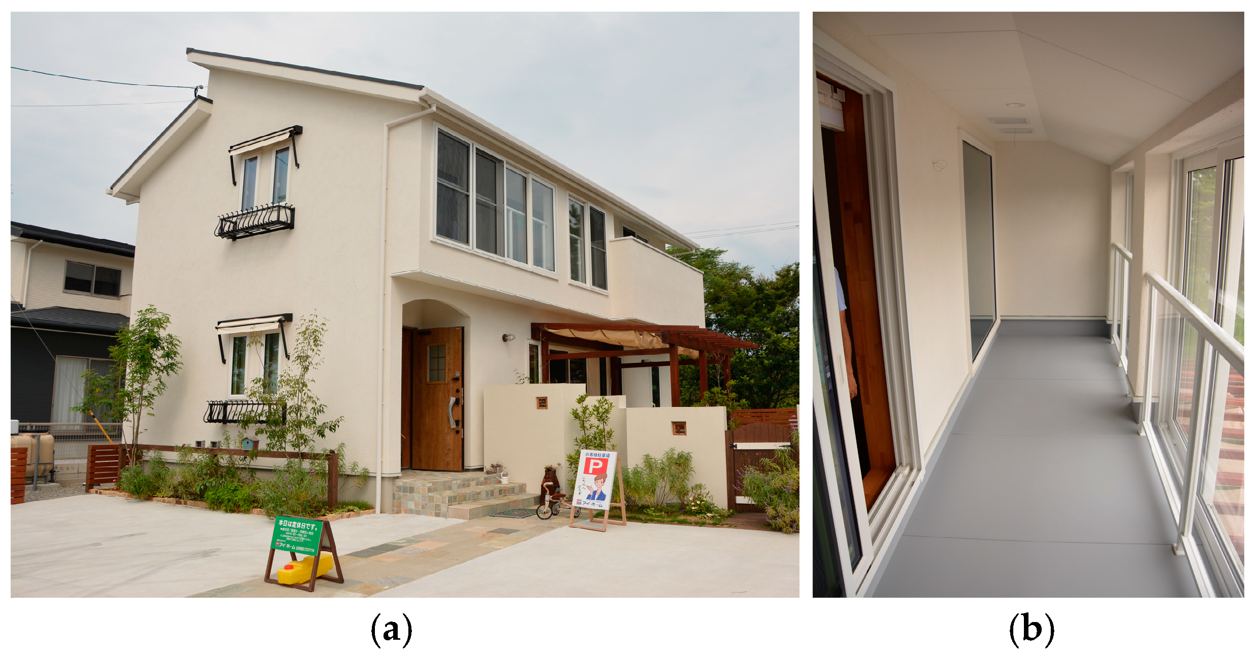
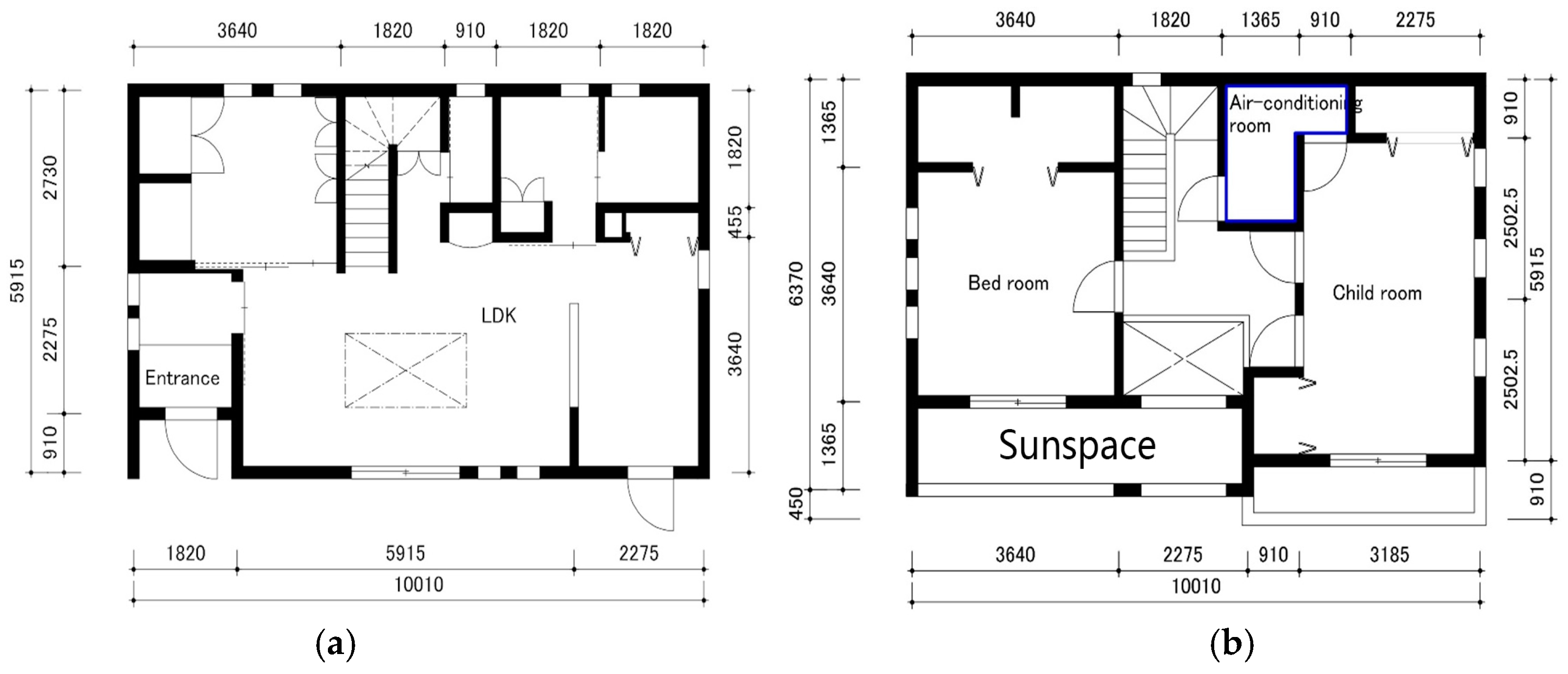
2. Overview of the Demonstration House and Its Air-Circulation System

The demonstration house is a two-story wooden house located in Miyazaki city, Miyazaki prefecture. Figure 1a,b shows the house’s outer appearance and the inside of the attached sunspace.
Table 1 shows the house’s specifications. The direct gain method and the attached sunspace method were applied. The heat collected in the attached sunspace was sent to the central HVAC machine room to reduce the heating load.
Figure 2 shows the air circulation system in winter. In the central air circulation system, external air was sent to the HVAC machine room through air filters and a total heat exchanger. The air in the central HVAC machine room was then sent to each room after a residential heat pump unit adjusted the temperature and humidity. The air in the rooms returned to the central HVAC machine room through vent layers in the wall, hallway, and duct. Part of the air was discharged to the outside by a total heat exchanger. The rest of the air was sent back to the rooms after going through the central HVAC machine room once more.

3. Numerical Simulation in Winter

3.1. Overview of the Numerical Simulation

This study used THERB for HAM software (TherbV72pmvERV+dsnv, 2016, Myonghyang Lee, Fukuoka, Japan) to investigate effective methods of using heat from inside the sunspace. THERB for HAM (Simulation Software of the Hygrothermal Environment of Residential Buildings for Heat, Air, and Moisture) is a dynamic calculation software that can calculate the temperature, humidity, heating, and cooling loads of multi-zone buildings [23]. Akihito Ozaki initially developed the THERB for HAM software. The calculated result of THERB for HAM was validated throughout the building energy simulation test (BESTEST) in Japan. The features of THERB for HAM are as follows [24]:
  • Combined calculation of heat and moisture transfer and airflow;
  • Prediction of the hygrothermal environment (temperature, humidity, predicted mean vote, and standard effective temperature);
  • Temperature and humidity control or predicted mean vote control;
  • Considering the time variation of convective heat and moisture transfer;
  • The forced and natural heat and moisture transfer coefficients were calculated for each part based on the dimensionless equation;
  • Strict geometric calculation of sunlit and shading areas of the outside and inside;
  • Multi-layer window model;
  • Multiple reflections of transmitted solar radiation through windows;
  • Nonlinearity of radiation heat transfer;
  • Mutual radiation between inside surfaces;
  • Network airflow model.
Figure 3a,b shows the floor plans of Model I. Figure 4a,b shows the floor plans of Model II. Heating loads and temperature were compared among Model I (a house with an attached sunspace on the second floor (equivalent to the demonstration house)), Model Iw (a house with a window on the exterior of the sunspace opened to external air), and Model II (a house with the attached sunspace both on the first and second floors). It was assumed the sunspace on the second floor of Model II was made of perforated metal and the air moved between the sunspace of the first and second floors.

3.2. Computation Conditions

Table 2 shows the computation conditions. Moving the air from a sunspace to the central HVAC machine room and taking the air from the sunspace to the adjacent rooms occurred only when the temperature within the sunspace was greater than 24 °C. The ventilation rates of the fan were controlled at 500 m3/h and the central HVAC was on throughout the house all day. The air circulation between the central HVAC machine room and each room was 840 m3/h for the living/dining/kitchen (LDK) area, 560 m3/h for the bedroom and the child’s room, and 150 m3/h for the other areas. Table 3 shows three different cases that were used for computation concerning air flow from the sunspace to the central HVAC machine room and air flow from the sunspace to adjacent rooms.
For Case 1, air flow from the sunspace to the central HVAC machine room on the second floor and air flow from the sunspace to the bedroom (Mode I and Model II) and living room (Model II) were performed. For Case 2, only air flow from the sunspace to the central HVAC machine room on the second floor was performed. For Case 3, air flow from the sunspace to the bedroom (Model I and Model II) and living room (Model II) were performed.

4. Results and Discussion

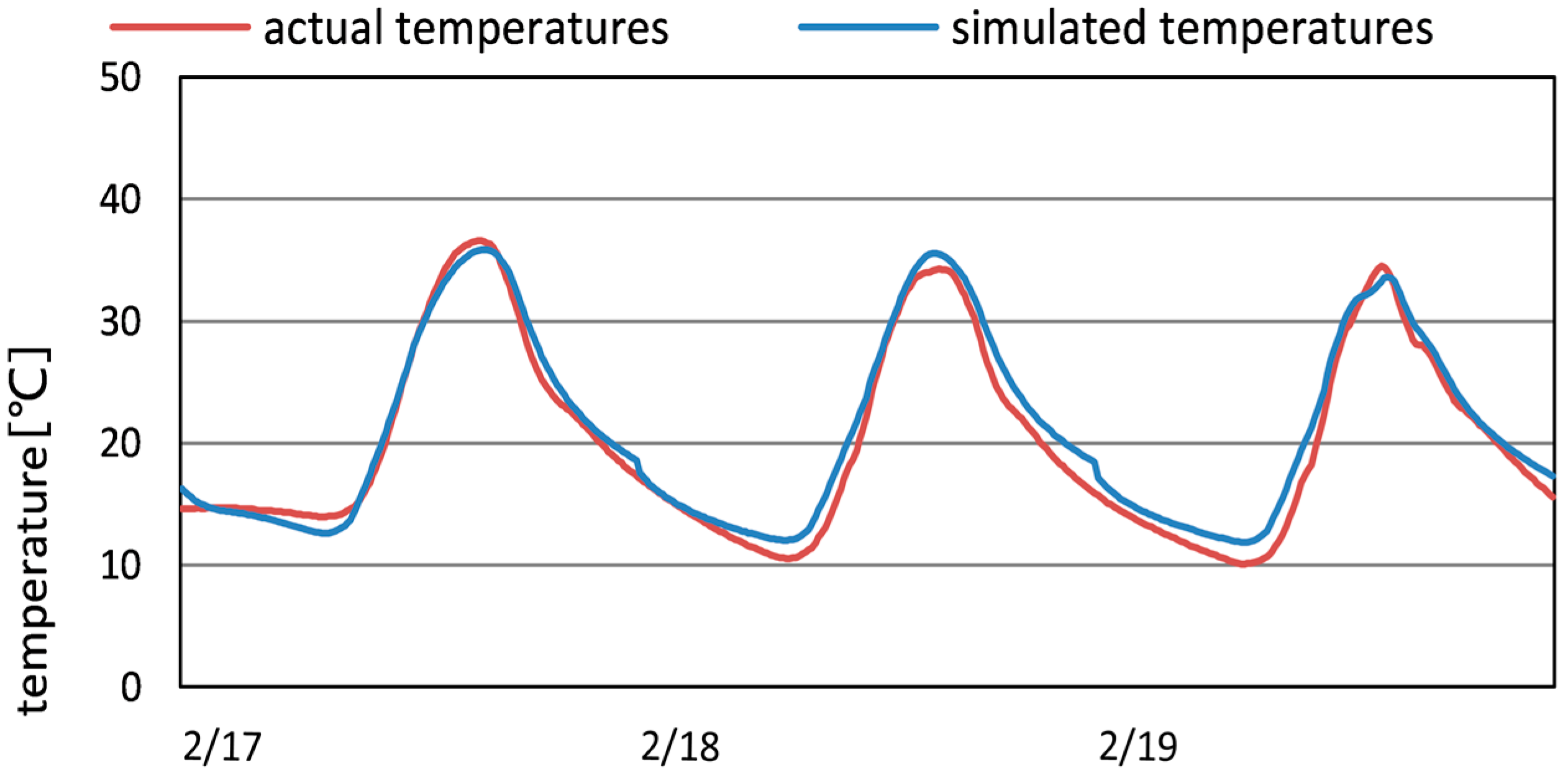
4.1. Verify the Accuracy of the Simulation Software

To verify the model by experiment, the measured meteorological data for Miyazaki was configured as a data input file of the simulation program based on the state of the demonstration house. The time step lasted 10 min. For the measurement, the RTR-503 device was used to measure the temperature and humidity of the sunspace and the room. The sensors were located in the sunspace center and the room center. The Vantage Pro2 Console device was used to measure the solar radiation, wind direction, wind speed, temperature, and humidity outdoors. Table 4 shows the accuracy and range of all measurement devices. The experiment was carried out with all-day heating. Figure 5 shows the calculated data and monitored data of the temperature inside the sunspace. The standard deviation of the temperature difference between the actual measurement and simulation was 1.04 °C. The fact that the simulated temperatures roughly matched the actual temperatures confirms that the simulation software is highly accurate.

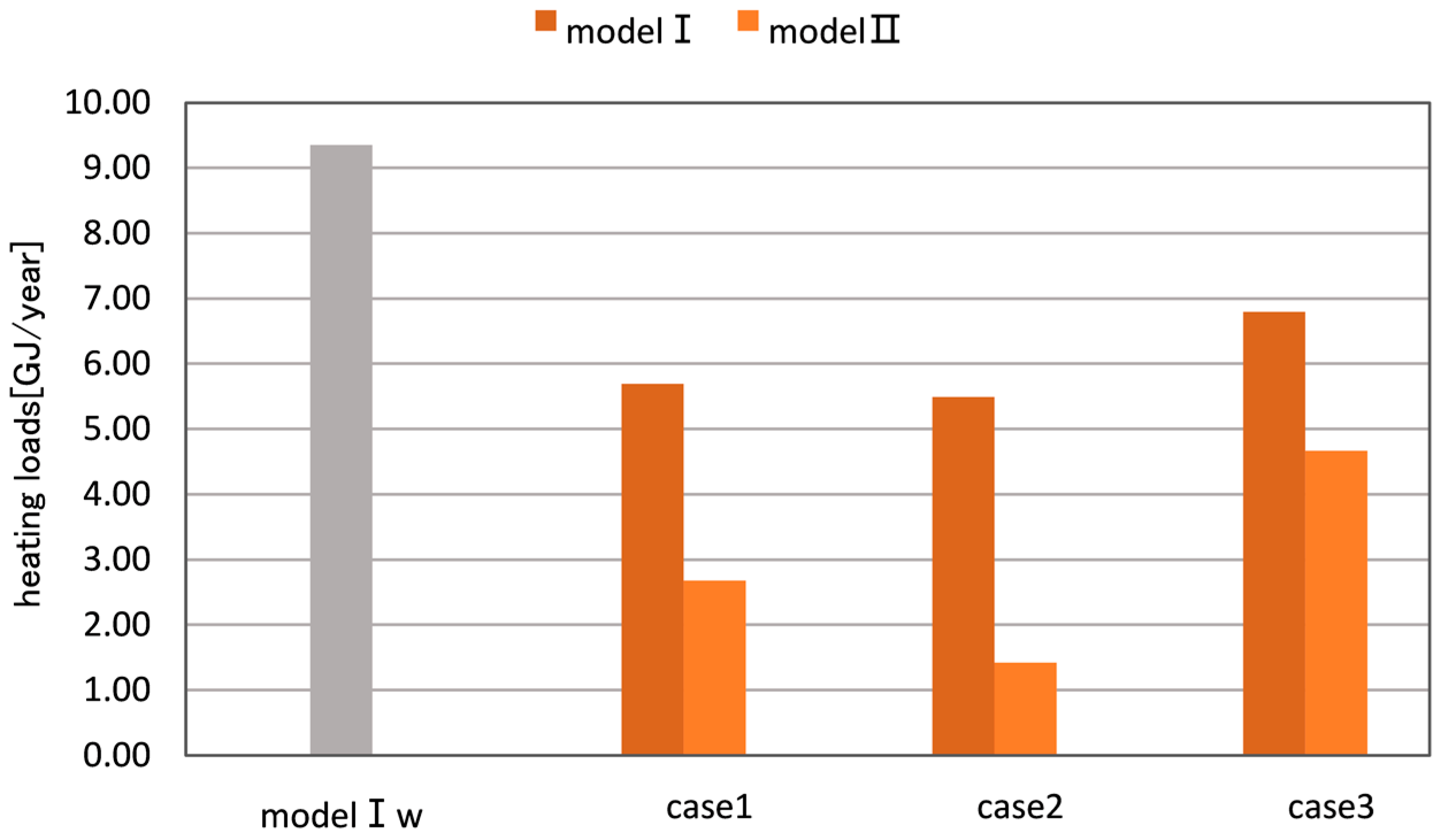
4.2. Heating Load Reduction Effect by the Attached Sunspace

Figure 6 shows the annual heating loads of models I and II. In all three cases, compared to the heating load reduction effect of Model Iw (opening the window on the exterior side of the sunspace), Model II (first- and second-floor sunspace) had a larger effect than Model I (first-floor sunspace). This result indicates that the larger capacity of sunspace structure had a greater heating load reduction effect. For models I and II, heating loads of Case 3 were smaller than for the other cases. This means that air flow to the central HVAC machine room had a better heating load reduction effect than air flow from the sunspace structure to adjacent rooms. Compared to the Model Iw, Model I could save approximately 39% of the total energy in Case 1, approximately 41% in Case 2, and approximately 27% in Case 3. The difference between Case 1 and Case 2 was small; therefore when the sunspace was only on the second floor, the air flow from the sunspace to the adjacent room did not affect the heating load. Compared to Model Iw, Model II saved approximately 71% of the total energy in Case 1, approximately 84% in Case 2, and approximately 50% in Case 3.

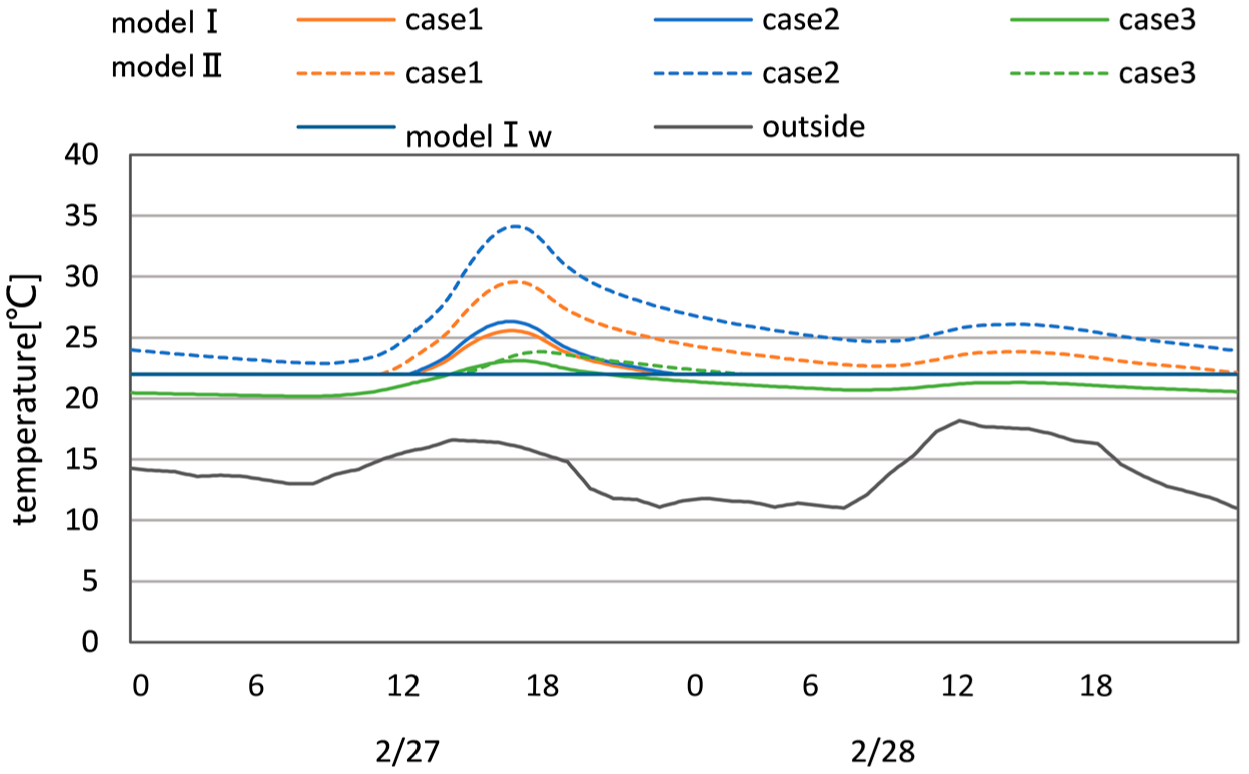
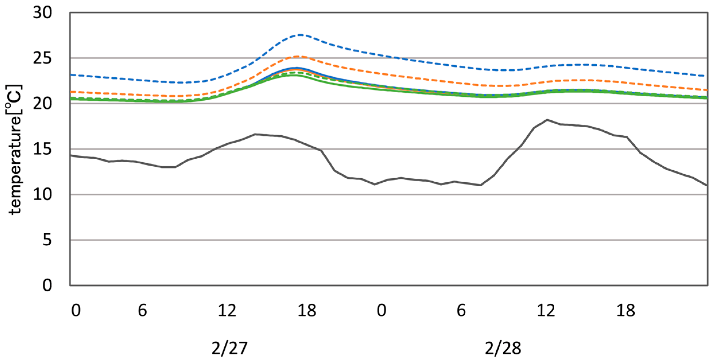
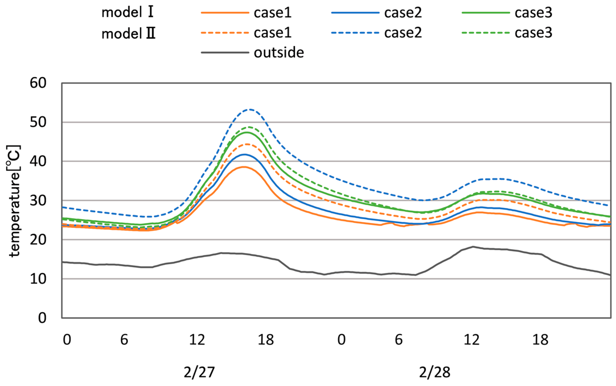
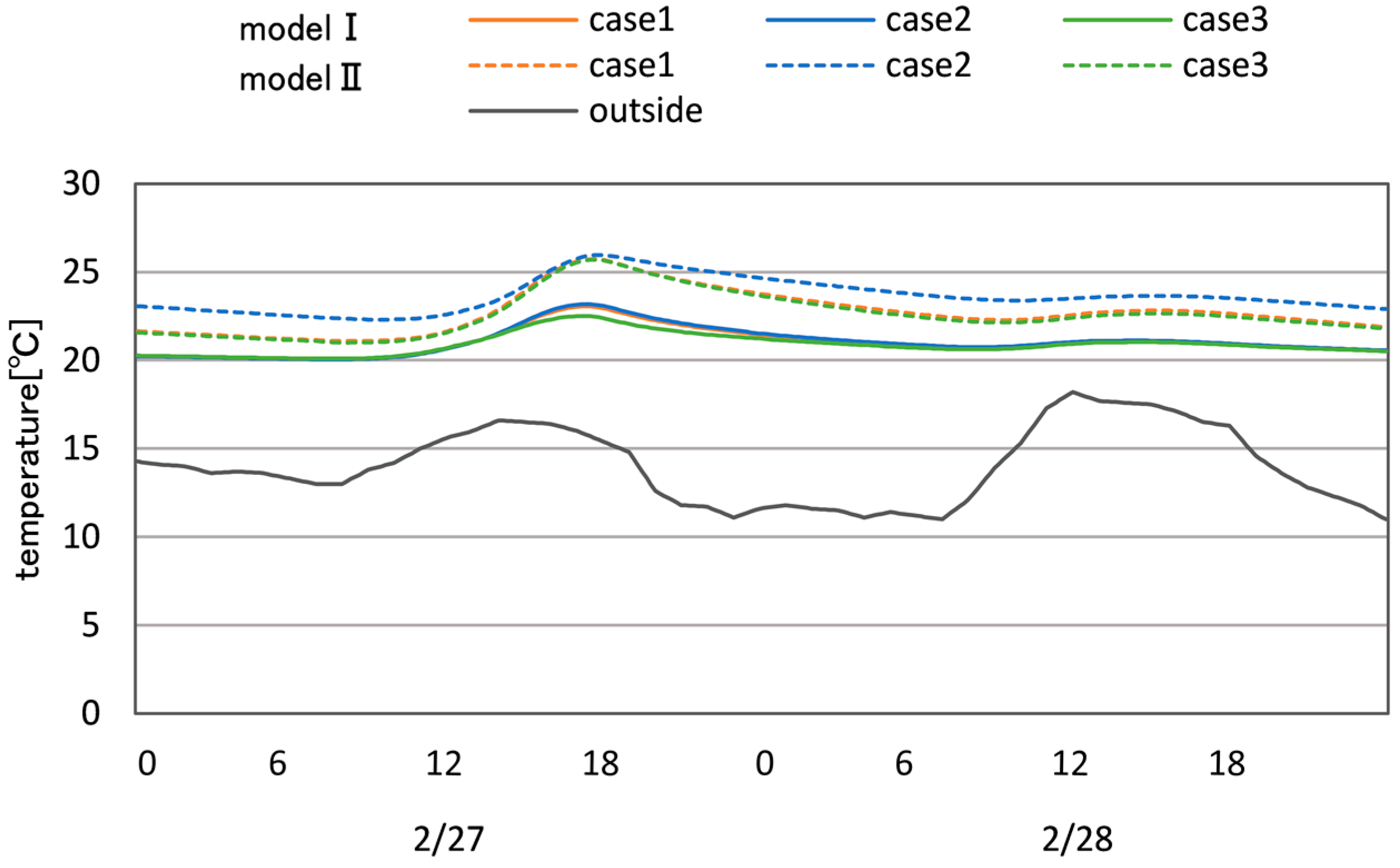
4.3. Room Temperature Associated with Air Movement within the Sunspace

For all cases, the temperature of the sunspace was higher in Model II than in Model I. Especially, the temperature for Case 2 of Model II was constantly above 24 °C, which was the set temperature to send the air from the sunspace to the HVAC machine room. This may be the main reason for the heating load reduction shown in Figure 6. There was almost no difference in the temperatures between models I and II for Case 3. This means that the capacity of the sunspace of Model I is large enough if the air is only taken from the sunspace to the adjacent rooms. Concerning the temperature change within the sunspace, in both models I and II in Figure 7, the temperature difference for Case 3 was small.
However, Model II’s temperature was always higher than Model I’s in the LDK room of Case 3 (Figure 8). Because Model II’s LDK room was next to the sunspace structure, this result indicates that taking the air from the sunspace to the adjacent room contributed to the temperature increase in the LDK room.
The bedroom was adjacent to the sunspace structure for Model I and Model II. For Model I, the temperature of Case 3 changed at the highest level (Figure 9). This was probably because the entire air within the sunspace was used for the bedroom. For Model II, the temperature of Case 1 changed at the highest level. For Models I and II, Figure 10 and Figure 11 show temperatures in the HVAC room and the child’s room, respectively. The temperature of Case 2 changed at the highest level. For Case 2 of Models I and II, as shown in Figure 10 and Figure 11, the temperature of the central HVAC room was high, and, consequently, the air temperature sent from the HVAC room to the child’s room was high.
Figure 12 shows the temperature fluctuation of each room for Case 2 of Model II. On a sunny day, the temperature exceeded 50 °C in the sunspace and 30 °C in the HVAC machine room, while the temperature in the living room remained around 25 °C. Sometimes, the temperature in the child’s room was higher than that of the bedroom and the living room. This may have been caused by the heat transfer from the HVAC machine room, as the child’s room was adjacent to the HVAC machine room.

5. Conclusions

In this paper, the authors studied the heating load reduction effect using heat from the sunspace and the temperature fluctuation of each room at the time of using heat from the sunspace. For the case of the all-day central HVAC system, it was confirmed that a larger capacity of sunspace structure, and not sending air from the sunspace space to the adjacent room, demonstrated a better heating load reduction effect. Compared with the house without the sunspace (Model Iw), the house with the sunspace on the second floor (Model I) could save approximately 41% of the total energy. The house with the sunspace on the first and second floors (Model II) could save approximately 84% of the total energy.
Sending heat from the sunspace space to the adjacent room led to a temperature increase in the adjacent rooms. However, if a construction plan is to have a sunspace structure only on the second floor, the house should be carefully designed, for example, by placing a living room on the second floor.
A limitation of the paper is that it ignores the energy consumed by the fan. For future work, a study of the optimal thickness of the sunspace and different storage materials (wall and floor) assisted by the use of a temperature-controlled fan for different climatic regions is suggested.

Author Contributions

Q.M., H.F. and T.K. conceived and designed the experiments; Q.M. and H.F. performed the experiments; Q.M. and H.F. analyzed the data; A.O., Y.K. and M.L. contributed analysis tools; Q.M. and X.W. wrote the paper.

Acknowledgments

This study was in part carried out under the Technology Development for the Application of Solar Energy in Housing Project at NEDO (New Energy and Industrial Technology Development Organization, Kawasaki, Japan). We are deeply grateful for the considerable contributions made by everyone at the FH Alliance (Aichi, Japan) and Ai Home, Inc. (Miyazaki, Japan). The authors would like to express their gratitude to Midori Inoue and Yohei Hama (The University of Kitakyushu, Kitakyushu, Japan) for their contributions.

Conflicts of Interest

The authors declare no conflicts of interest.

References

  1. Lee, H.; Ozaki, A.; Lee, M. Energy saving effect of air circulation heat storage system using natural energy. Build. Environ. 2017, 124, 104–117. [Google Scholar] [CrossRef]
  2. Babaee, F.; Fayaz, R.; Sarshar, M. The optimum design of sunspaces in apartment blocks in cold climate. Archit. Sci. Rev. 2016, 59, 239–253. [Google Scholar] [CrossRef]
  3. Bakos, G.C.; Tsagas, N.F. Technology, thermal analysis and economic evaluation of a sunspace located in northern Greece. Energy Build. 2000, 31, 261–266. [Google Scholar] [CrossRef]
  4. Mihalakakou, G. On the use of sunspace for space heating/cooling in Europe. Renew. Energy 2002, 26, 415–429. [Google Scholar] [CrossRef]
  5. Lu, S.; Tong, H.; Pang, B. Study on the coupling heating system of floor radiation and sunspace based on energy storage technology. Energy Build. 2018, 159, 441–453. [Google Scholar] [CrossRef]
  6. Ulpiani, G.; Giuliani, D.; Romagnoli, A.; di Perna, C. Experimental monitoring of a sunspace applied to a NZEB mock-up: Assessing and comparing the energy benefits of different configurations. Energy Build. 2017, 152, 194–215. [Google Scholar] [CrossRef]
  7. Asdrubali, F.; Cotana, F.; Messineo, A. On the evaluation of solar greenhouse efficiency in building simulation during the heating period. Energies 2012, 5, 1864–1880. [Google Scholar] [CrossRef]
  8. Chiesa, G.; Simonetti, M.; Ballada, G. Potential of attached sunspaces in winter season comparing different technological choices in Central and Southern Europe. Energy Build. 2017, 138, 377–395. [Google Scholar] [CrossRef]
  9. Bastien, D.; Athienitis, A.K. Passive thermal energy storage, part 2: Design methodology for solaria and greenhouses. Renew. Energy 2017, 103, 537–560. [Google Scholar] [CrossRef]
  10. Rempel, A.R.; Rempel, A.W.; Gates, K.R.; Shaw, B. Climate-responsive thermal mass design for Pacific Northwest sunspaces. Renew. Energy 2016, 85, 981–993. [Google Scholar] [CrossRef]
  11. Rempel, A.R.; Rempel, A.W.; Cashman, K.V.; Gates, K.N.; Page, C.J.; Shaw, B. Interpretation of passive solar field data with EnergyPlus models: Un-conventional wisdom from four sunspaces in Eugene, Oregon. Build. Environ. 2013, 60, 158–172. [Google Scholar] [CrossRef]
  12. Monge-Barrio, A.; Sánchez-Ostiz, A. Energy efficiency and thermal behaviour of attached sunspaces, in the residential architecture in Spain. Summer Conditions. Energy Build. 2015, 108, 244–256. [Google Scholar] [CrossRef]
  13. Owrak, M.; Aminy, M.; Jamal-Abad, M.T.; Dehghan, M. Experiments and simulations on the thermal performance of a sunspace attached to a room including heat-storing porous bed and water tanks. Build. Environ. 2015, 92, 142–151. [Google Scholar] [CrossRef]
  14. Ignjatović, D.; Jovanović Popović, M.; Kavran, J. Application of sunspaces in fostering energy efficiency and economical viability of residential buildings in Serbia. Energy Build. 2015, 98, 3–9. [Google Scholar] [CrossRef]
  15. Hilliaho, K.; Mäkitalo, E.; Lahdensivu, J. Energy saving potential of glazed space: Sensitivity analysis. Energy Build. 2015, 99, 87–97. [Google Scholar] [CrossRef]
  16. Zhu, X.; Liu, J.; Yang, L.; Hu, R. Energy performance of a new Yaodong dwelling, in the Loess Plateau of China. Energy Build. 2014, 70, 159–166. [Google Scholar] [CrossRef]
  17. Sánchez-Ostiz, A.; Monge-Barrio, A.; Domingo-Irigoyen, S.; González-Martínez, P. Design and experimental study of an industrialized sunspace with solar heat storage. Energy Build. 2014, 80, 231–246. [Google Scholar] [CrossRef]
  18. Aelenei, D.; de Azevedo Leal, H.; Aelenei, L. The Use of Attached-sunspaces in Retrofitting Design: The Case of Residential Buildings in Portugal. Energy Procedia 2014, 48, 1436–1441. [Google Scholar] [CrossRef]
  19. Chen, Y.; Tong, Z.; Malkawi, A. Investigating natural ventilation potentials across the globe: Regional and climatic variations. Build. Environ. 2017, 122, 386–396. [Google Scholar] [CrossRef]
  20. Tong, Z.; Chen, Y.; Malkawi, A. Estimating natural ventilation potential for high-rise buildings considering boundary layer meteorology. Appl. Energy 2017, 193, 276–286. [Google Scholar] [CrossRef]
  21. Oliveti, G.; Arcuri, N.; De Simone, M.; Bruno, R. Solar heat gains and operative temperature in attached sunspaces. Renew. Energy 2012, 39, 241–249. [Google Scholar] [CrossRef]
  22. Bataineh, K.M.; Fayez, N. Analysis of thermal performance of building attached sunspace. Energy Build. 2011, 43, 1863–1868. [Google Scholar] [CrossRef]
  23. Ozaki, A.; Watanabe, T.; Takase, S. Simulation software of the hydrothermal environment of buildings based on detailed thermodynamic models. In Proceedings of the eSim 2004 Canadian Conference on Building Energy Simulation, Vancouver, BC, Canada, 10–11 June 2004; pp. 45–54. [Google Scholar]
  24. Ozaki, A.; Tsujimaru, T. Prediction of hygrothermal environment of buildings based upon combined simulation of heat and moisture transfer and airflow. J. Int. Build. Perform. Simul. Assoc. 2006, 16, 30–37. [Google Scholar]
Figure 1. The demonstration house: (a) the outer appearance; and (b) the inside of the attached sunspace.
Energies 11 01192 g001
Figure 2. Air circulation system in winter.
Energies 11 01192 g002
Figure 3. Model I floor plans: (a) 1st floor; and (b) 2nd floor.
Energies 11 01192 g003
Figure 4. Model II floor plans: (a) 1st floor; and (b) 2nd floor.
Energies 11 01192 g004
Figure 5. The monitored and calculated data of the temperature inside the sunspace.
Energies 11 01192 g005
Figure 6. The annual heating loads of Model Iw, Model I, and Model II.
Energies 11 01192 g006
Figure 7. Temperature within the attached sunspace.
Energies 11 01192 g007
Figure 8. Living/dining/kitchen (LDK) room temperature.
Energies 11 01192 g008
Figure 9. Bedroom temperature.
Energies 11 01192 g009
Figure 10. Temperature in the HVAC room.
Energies 11 01192 g010
Figure 11. Child’s room temperature.
Energies 11 01192 g011
Figure 12. Temperature fluctuation of each room for Case 2 of Model II.
Energies 11 01192 g012
Table 1. Specifications of the house.
LocationMiyazaki
Orientation13.5 degrees southwest
ClimateHot and humid in summer and cool in winter
Total floor area115.5 (m2)
Total building skin area350.9 (m2)
Direct gain opening area8.1 (m2)
Sunspace opening area9 (m2)
GlazingSunspace (outside)Pair glass
OthersTriple Shannon IIs
Overall heat transfer coefficient of the skin0.26 (W/m2 K)
Air conditioner roomAir-conditioner, DC motor, and the central air-circulation system
Ventilating equipmentTotal enthalpy heat exchanger
Table 2. Computation conditions.
Computation AreaMiyazaki City
Weather dataExpanded AMEDAS Weather Data (Miyazaki, reference year)
Computation periodNovember–March
Computation time interval10 min
Heating methodCentral HVAC, all-day heating
Heating set temperature22 °C
Heat generation within a roomNothing
Table 3. Cases.
Table 3. Cases.
CaseAir Flow from the Sunspace to the Central HVAC Machine RoomAir Flow from the Sunspace to the Adjacent Rooms
Case 1YesYes
Case 2YesNo
Case 3NoYes
Table 4. Uncertainties of measurement devices.
DeviceMeasuring ParameterRangeAccuracy
RTR-503Temperature0–55 °C±0.3 °C
Humidity10%–95%±5% relative humidity (RH)
Vantage Pro2 ConsoleSolar radiation0–1800 W/m2±5% of full scale
Wind direction0–360°±3°
Wind speed0–809 m/s±1 m/s
Temperature−40–+65 °C±0.5 °C
Humidity1%–100%±3% RH

