Impact of Cyber Attacks on High Voltage DC Transmission Damping Control


Pacific Northwest National Laboratory, Richland, WA 99354, USA
*
Author to whom correspondence should be addressed.
Energies 2018, 11(5), 1046; https://doi.org/10.3390/en11051046
Submission received: 5 April 2018
/
Revised: 16 April 2018
/
Accepted: 18 April 2018
/
Published: 24 April 2018
(This article belongs to the Section F: Electrical Engineering)
Abstract
:Hybrid AC/HVDC (AC-HVDC) grids have evolved to become huge cyber-physical systems that are vulnerable to cyber attacks because of the wide attack surface and increasing dependence on intelligent electronic devices, computing resources and communication networks. This paper, for the first time, studies the impact of cyber attacks on HVDC transmission oscillation damping control.Three kinds of cyber attack models are considered: timing attack, replay attack and false data injection attack. Followed by a brief introduction of the HVDC model and conventional oscillation damping control method, the design of three attack models is described in the paper. These attacks are tested on a modified IEEE New England 39-Bus AC-HVDC system. Simulation results have shown that all three kinds of attacks are capable of driving the AC-HVDC system into large oscillations or even unstable conditions.
1. Introduction
1.1. Motivation
High voltage direct-current (HVDC) power transmission systems are becoming popular in modern electric grids, which are faced with increasing power demands and already strained AC transmission lines [1]. HVDC is able to deliver renewable generation to the main grid more efficiently and transfer bulk power between unsynchronized AC transmission systems. It also can be used for additional services other than bulk power transfers, such as damping power system inter-area oscillation [2]. At the same time, AC-HVDC grids have evolved to become huge cyber-physical systems (CPSs) that are vulnerable to cyber attacks because of the wide attack surface and increasing dependence on intelligent electronic devices, computing resources and communication networks [3,4]. The security and stability of AC-HVDC transmissions against cyber-attacks are essential to modern electric power systems.
1.2. Literature Survey
The application of a DC line to provide power system stabilization was being considered almost as soon as HVDC became practical. The intrinsic reason for power system inter-area oscillation is the real power unbalance, which could be mitigated by modulating the transferred power on the HVDC lines. In the early stage of HVDC, it was used to damp inter-area oscillations by modulating the DC power flow in proportion to the frequency difference between the two ends of the line [5]. Some real-world tests were performed on actual power systems to validate the system model with the design of a modulation function for HVDC transmissions [6,7].
The last several decades have witnessed rapid advances in AC-HVDC power systems because of the pervasive use of information and communication technologies. With the development of wide-area measurement systems and intelligent electronic devices, many HVDC transmission-based control methods have been studied while looking for promising solutions for damping inter-area oscillations in large systems [8,9]. Advanced control strategies along with new technologies have been tested to enhance system stability significantly and provide remarkable improvement in damping inter-area low frequency oscillations in AC-HVDC systems [10,11,12,13,14]. Azad et al. [10] proposed a model predictive control (MPC)-based scheme on a line commutated converter (LCC) HVDC link, and the main feature of this type of control was its ability to cope with hard constraints on the inputs, outputs and states. The MPC-based method was also compared to a linear quadratic control-based damping strategy, and it was found to be superior. Roberson et al. [11] proposed a loop-shaping method to control HVDC and damp inter-area oscillations by bending the Nyquist curve away from the critical point. Pipelzadeh et al. [12] presented a coordinated control method of an offshore wind farm and onshore HVDC converter to provide effective damping on inter-area oscillations, avoiding problems with undesirable voltage variations or inadequate damping by using only either the wind farm or the HVDC converter. The use of HVDC with various flexible AC transmission system (FACTS) devices has also been studied to damp power system oscillations [13,14]. The static synchronous series compensator, static VAR compensator and thyristor-controlled series compensator were used as supplementary controls of HVDC to enhance the overall stability of large-scale interconnected system with the introduction of suitable wide area control signals. The common requirements of these HVDC transmission damping control schemes are high-quality measurements from phasor measurement units (PMUs) and fast communication techniques. There is no doubt that modern AC-HVDC systems are evolving into CPSs that have sophisticated control mechanisms and communication networks. However, along with the benefits received from the wide-area measurements and fast computation and communication associated with CPSs comes increased vulnerability to cyber attacks.
AC-HVDC systems usually implement an enormous number of cyber devices and communication networks that are susceptible to failures; any attack that jeopardizes the cyber infrastructure will inevitably affect system security and stability [15,16,17,18]. The AC-HVDC system’s wide attack surface and its increasing dependence on communication make it subject to all major cyber attacks, including denial of service (DoS) [19,20], replay [21] and false data injection attack (FDIA) [22]. The likelihood of cyber attacks triggering potentially devastating results is also real, and the impacts of cyber attacks on AC-HVDC systems are not well understood. In recent years, research on cyber security topics in electric grids has made remarkable progress. With the development of technologies, the traditional power system is undergoing a comprehensive transformation to a smarter, computer- and communication-based grids. Cyber security issues are increasingly closely related to all aspects of the electric grids in generation, transmission, distribution and the end-users [23,24,25,26,27,28]. Many interesting issues have been addressed on the AC power system, but few studies have focused on the DC grids. Beg et al. [29] presented a framework for detecting potential FDIAs in low-voltage cyber-physical DC microgrids. The detection of an FDIA is achieved by comparing sets of inferred candidate invariants with the actual invariants that do not change over time; any mismatch indicates the presence of an FDIA. Zhong et al. [30] studied security vulnerabilities, such as side channel analysis, DoS attacks and privacy issues, also in low-voltage microgrids. They concluded that critical networks should remain functional in order to maintain the overall reliability of the system even if certain parts of the microgrid were compromised. Mantooth et al. [31] introduced a medium voltage DC and hybrid microgrid security test bed for security analysis of software and hardware attacks, as well as security solutions. The test bed was built on a real power facility for the purpose of rigorously testing the cyber security issues in the microgrid in a realistic power platform. However, no existing literature has addressed the cyber-security issues of AC-HVDC systems.
1.3. Contributions
In this paper, we studied the impact of cyber attacks on HVDC transmission-based oscillation damping control. Three major cyber attack models were considered: timing attack (a DoS attack), replay attack and false data injection attack (FDIA). The three major cyber attack models were introduced and designed to jeopardize the performance of the HVCD oscillation damping controller. Well-constructed attacks are implemented and tested on the HVDC link in a modified IEEE New England 39-Bus AC-HVDC system. The contribution of this paper comes from two aspects: (1) it is the first time the cyber-security issue has been studied for HVDC damping controls; (2) we have proven that all three major cyber attack models are capable of driving an AC-HVDC system into unstable conditions if attackers have careful attack plans and necessary knowledge of the power system.
1.4. Organization of Paper
The remaining parts of this paper are organized as follows. Section 2 briefly introduces the HVDC system model and power oscillation damping controls. In Section 3, the three cyber attacks and model constructions are discussed. Section 4 describes the simulation overview and the test system. Section 5 presents the simulation results. Finally, conclusions are reported in Section 6.
2. HVDC System with Damping Control
2.1. HVDC Models
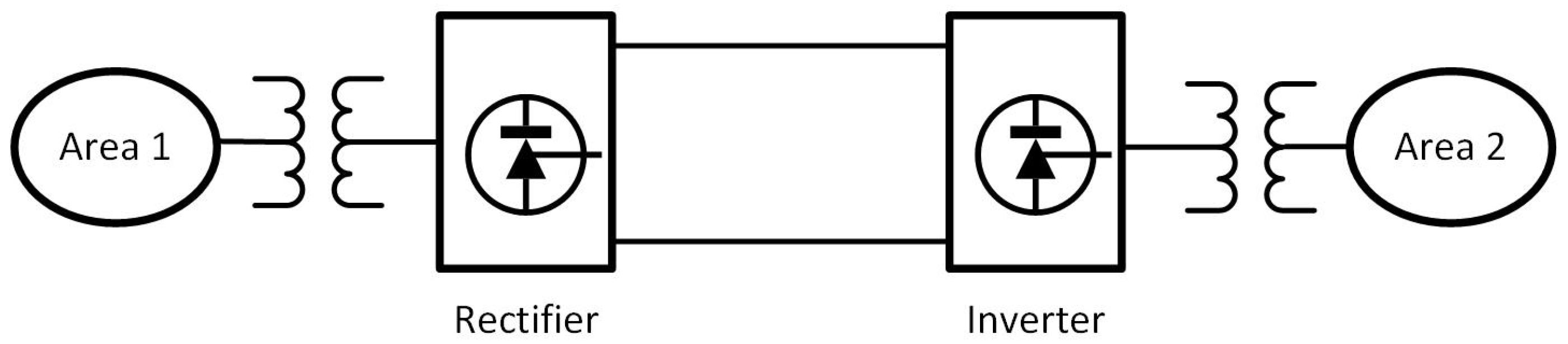
A diagram of a two-terminal LCC-HVDC system is shown in Figure 1. It consists of a controlled rectifier and inverter at the respective terminals, both of which are fed from tap-changing transformers.
The DC line models are represented by a T-equivalent as [32]:
where , , and are the equivalent DC line resistance, capacitance, inductance and DC voltage, and are the voltage at the rectifier and inverter and and are the DC currents. The active and reactive power of the HVDC converter can be obtained as follows:
where and are the firing and extinction angles of the converters.
2.2. Conventional HVDC Oscillation Damping Control
The inter-area oscillations, which occur as groups of generators can move together against other groups of generators, are detrimental to the system stability and prevent the maximum power transfer on the tie-lines. Severe oscillations may even trip the generators and cause cascade failures in the system. Because the power flow over HVDC links can be controlled independently of the phase angle between the source and load, HVDC has been recognized as an effective way for the mitigation of inter-area oscillations of interconnected power systems, which in turn would improve system reliability.
There are many HVDC damping control schemes that have been proposed in the literature, some of them have been implemented in the real world [6,33]. In this work, the implemented HVDC damping controller is based on a prototype using the real-time PMU measurements in [33]. This controller represents the most conventional method in the real world, and it has been installed on the west-coast Pacific DC Intertie (PDCI) to modulate real power. The control logic is based on the frequency difference at the PDCI terminals. The frequency difference is obtained by passing signals of the electrical angle difference from PMUs through a derivative filter. Figure 2 represents the typical damping controller for HVDC transmission. When the HVDC is operating at steady state and there is no oscillation, the frequencies at the terminals are the same. The change to transmitted power is zero, and the HVDC is working at the nominal states. When an inter-area oscillation occurs, the frequency difference at the HVDC terminals is non-zero and is amplified through a proportional gain [34]. The amplified signal is used as a feedback to modulate HVDC transmitted power and damp the oscillation. The feedback signal is calculated as follows:
where and are the frequencies at the rectifier and inverter terminals of HVDC transmission, K is the proportional gain and is the modulation power.
3. Construction of the Cyber Attack Model
3.1. Timing Attack
A timing attack is a kind of DoS attack that blocks the communication between data senders and receivers with an induced false time stamp [35]. In the wide-area monitoring system of electric grids, coordinated universal time among PMUs uses a common time reference from a global positioning system that has time-synchronization protocols, which could be attacked by either changing the time stamp or adding an intended delay for malicious purposes. Because the timing attack could only involve delaying messages, it would still be able to jeopardize the controllers even if synchronization messages are encrypted and/or authenticated [36]. In this study, it was assumed that attackers would intentionally delay the measurements received by the damping controller in Equation (6). Specifically, the attacker would change the time stamp and introduce an intended delay for the measurements from the remote terminal of the HVDC transmission.
The principle of timing attacks on the HVDC damping controller is shown in Figure 3. When the timing attack occurs, the two frequency signals are no longer synchronized. Apparently, the timing attacks would not work during normal operations since the frequencies at two terminals are both at nominal values. The changes to transmitted power are always zero regardless of the time delays. However, the time delay could generate large errors during system transients when the terminal frequencies are different. To study the impact of a timing attack on HVDC damping controls, transient events were simulated such that the inter-area oscillation modes were triggered and the damping controller started to modulate the transmitted power based on the frequencies at the two terminals. Different levels of timing attacks were constructed in the study.
3.2. Replay Attack
A replay attack is a special attack that maliciously repeats a valid data transmission to the signal receiver. A replay attack is realized in two steps. In the first step, a valid data transmission is monitored and recorded by the attacker. Then, the attacker maliciously replaces the transmitted data with pre-recorded data, which are sent repeatedly to the receiver [21]. Because the replayed data are valid messages that match the CPS, there is high a possibility that they could bypass the detection algorithms and successfully fool the receiver without being detected. To illustrate, the valid data received by the HVDC controller during time [] as:
where , represents the instantaneous transferred data and M is a indicator function with:
The corrupted signals that are repeatedly sent to the receiver are:
The principle of replay attacks on the HVDC damping controller is shown in Figure 4. To construct the replay attack model, the attacker should first get access to the valid signal that is sent to the HVDC controller. Then, a part of the valid signal is recorded by the attacker maliciously. Finally, the attacker will intercept the real-time valid signals that are being sent to the HVDC controller and replace them with the recorded signals. The recorded signals will be played repeatedly to fool the receiver of the HVDC controller. There are two options to apply the replay attack. The first option is to record the valid data during transient events and then replay the records during steady state operations; thus, the normal operation will be disturbed, and transient events are generated. The second option is to record the valid signals during steady state operations and then replay the records during transient events. In constructing a timing attack that can only work during transient events, the replay attack is suitable for any system status.
In this study, the above two options are studied with two simulation scenarios. In the first scenario, the frequency measurements at the HVDC remote terminal are recorded during a severe transient event and replayed during normal operations to the damping controller. The frequency differences between the rectifier and inverter change the transmitted power according to Equation (6), could trigger the inter-area oscillation of the system and further disturb the operation of the damping controller. In the second scenario, the frequency measurements at the HVDC terminals are recorded when no system disturbances exist. Therefore, the recorded frequency difference at the two terminals is zero. The recorded data are sent to the HVDC controller during large system transient events, and therefore, the capability of using HVDC to damp inter-area oscillation is disabled.
3.3. False Data Injection Attack
An FDIA compromises measurements from the sensor network and adversely injects false data with errors to deceive the operators or controllers. Unlike the timing attack or replay attack that feeds the valid signal (although the timing is wrong or the signal is repeatedly played) to the HVDC damping controller, an FDIA assaults the integrity of measurements by replacing the true values with false ones, without being detected. Recent studies have shown that traditional authentication mechanisms cannot prevent an FDIA if a certain number of sensor nodes are compromised [22].
In the power system, FDIA is an important type of cyber-attack that stealthily circumvents the regular bad data detection (BDD) process. A successful FDIA would cause the state estimator to send erroneous estimates of the measurements and operational states to the operators or controllers, thereby jeopardizing the normal operation of the power system. The state estimation process in the power system is often simplified through DC power flow approximation. A general DC state estimation model is given as: [37]
where z is the measurement from sensors, x represents the system states, e represents the measurement errors and H is the Jacobian matrix of the system model. Hx denotes the functional dependency between measurements and state variables.
The state estimation process in the power system is intended to find the best estimates of system states given all the measurements, which most of the time are redundant, from the sensor networks. is usually computed using the weighted least square (WLS) method that finds the best solution for minimizing WLS errors by solving the optimization problem [38],
where W is the diagonal weight matrix and is the variance of the measurement errors associated with the i-th meter. The solution of the optimization problem is:
Raw measurements z may contain some inaccurate or bad data because of sensor errors or large noise signals, which should be excluded from the state estimation process to assume the confidence level in the best state estimates . In power systems, the BDD process is used to eliminate the possible measurement errors. A common approach to detecting bad measurements is to test the largest normalized residual (LNR) and compare it with a preset threshold . If there are no bad data in the measurements, the LNR should be smaller than :
Otherwise, the bad measurement will be detected if the LNR is larger than . However, an FDIA could circumvent the BDD process if the attacker compromises a few sensors with careful planning and enough knowledge of the power system. In other words, an FDIA would inject false data into the state estimation process with LNRs smaller than . To construct an FDIA, the attacker needs to compromise the measurements with so that the output of the state estimation process could be the expected false system states :
where and are the difference between the false values and the original correct values. If the attacker can compromise the measurements according to the relationship , the BDD process could be successfully circumvented.
Proof: Assume Equation (12) is satisfied and there are no bad measurements in the system before the cyber attack. After the FDIA is applied, the solution of state estimation is as follows:
Therefore, if the relationship is guaranteed, the new false values satisfy the state estimation process. Regarding the BDD process, the new LNR is as follows:
The new LNR is still smaller than the threshold of the BDD process, thus an FDIA would successfully circumvent the BDD process if the attacker can compromise the sensor with the relationship . In this study, the FDIA was constructed to generate false data that circumvent the BDD process and inject false frequency data to the HVDC damping control.
4. Test System and Simulation Overview
A modified IEEE New England 39-Bus system has been built to serve as the AC-HVDC test system, as shown in Figure 5. A 500-kV, 700-MW rated HVDC line was added between Buses 16 and 19, connecting the northeastern area with the southeastern area. The power flow direction is from south to north. To figure out the oscillation modes in this test system, a small-signal stability study is performed as follows [39].
The linearized model for the test system is expressed as:
where are the perturbed system states, v is the vector of the network bus voltages, is the current injection into the network, is a prefix representing the perturbed value and are the system coefficient matrices. The interconnecting network is represented by the node equation:
where is the admittance matrix of the system. Therefore, the overall system state equation is formed by eliminating and :
where is the complete system state matrix. The eigenvalues (with frequency between 0.1 and 1 Hz and a damping ratio less than 5%) of directly give the information about the oscillation modes.
It is found that there are three low-frequency inter-area oscillation modes in the modified system, as summarized in Table 1. Apparently, Oscillation Mode 2 is the most severe one because the corresponding damping ratio is the smallest. Mode 2 represents the generator oscillation of the northern part of the system against the generators of the southern part. The added HVDC line is supposed to provide damping controls for Mode 2 to increase the entire stability of the system. A schematic overview of the application of the timing attack, replay attack and FDIA on the HVDC damping controller is shown in Figure 6. The three cyber attacks are applied sequentially to the test system, and they are supposed to jeopardize the normal operation of the damping controller as discussed in Section 3. The simulation results are shown as follows.
5. Simulation Results
5.1. Timing Attack Results
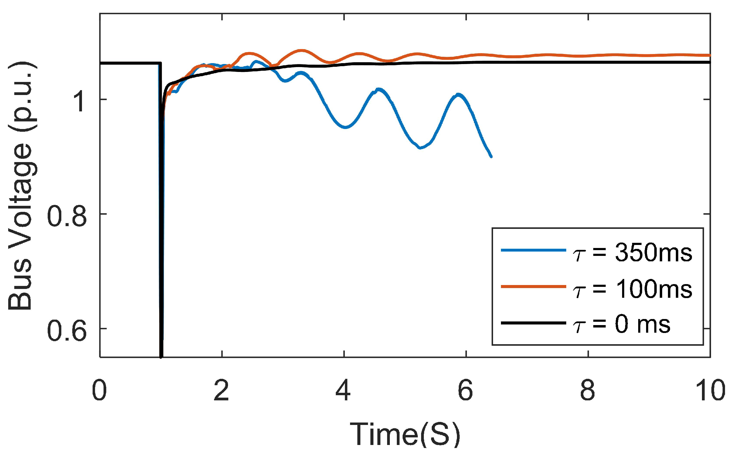
In this simulation case, the AC-HVDC system is operating normally at the beginning. At time 1.0 s, a temporary three-phase fault happens on Lines 23–36, and it is tripped 1.5 cycles later. The fault is cleared another two cycles later, and the line is reconnected. This event generates large transients and triggers inter-area oscillations in the system. The HVDC damping controller is working to damp the inter-area oscillation by changing the power transfer on the DC line. The timing attack starts to add intended delays to the input signals that are fed to the HVDC damping controllers.
Figure 7 and Figure 8 show the Bus 23 voltage magnitudes and machine 5–10 angle differences with respect to different levels of timing attacks (delays). When the delay is zero (no timing attack), the oscillation is damped very quickly. That means the HVDC damping controller is very effective at reducing the transients of inter-area oscillation and increases the overall system stability. When the timing attack starts and the intended delay is small (100 ms), the HVDC damping controller is still able to damp the oscillations, but it takes a longer period of time to drive the system back to the steady state. This means the HVDC damping controller can withstand a certain level of timing attacks. However, when the delay is very large (350 ms), the bus voltage drops greatly, while the machine angle difference increases greatly, and the system gradually loses stability until the simulation blows out. Therefore, the timing attack is able to drive the system into an unstable situation with a severe attack level.
5.2. Replay Attack Results
5.2.1. Attack Occurs During Normal Operation
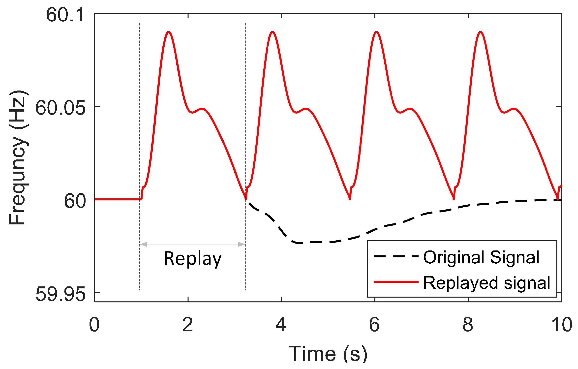
In this simulation case, the system is operating normally, and there is no fault event. To generate a replay attack, the frequency measurements at the HVDC remote terminal were recorded in advance during a severe transient event and replayed during normal operations to the damping controller. The recorded and replayed signals are shown in Figure 9. The black dashed curve represents some valid data of the HVDC remote side frequency during a historical transient event. The most severe transient information is recorded and played repeatedly by the attacker at time 1.0 s as the red solid curve. Note that the frequency values at the start and end points are identical, which helps reduce the chance of being detected when the same segment of the signal is repeatedly sent to the HVDC damping controller.
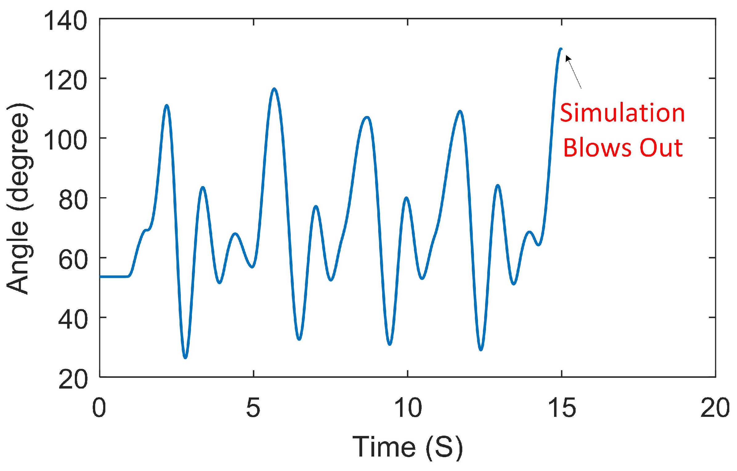
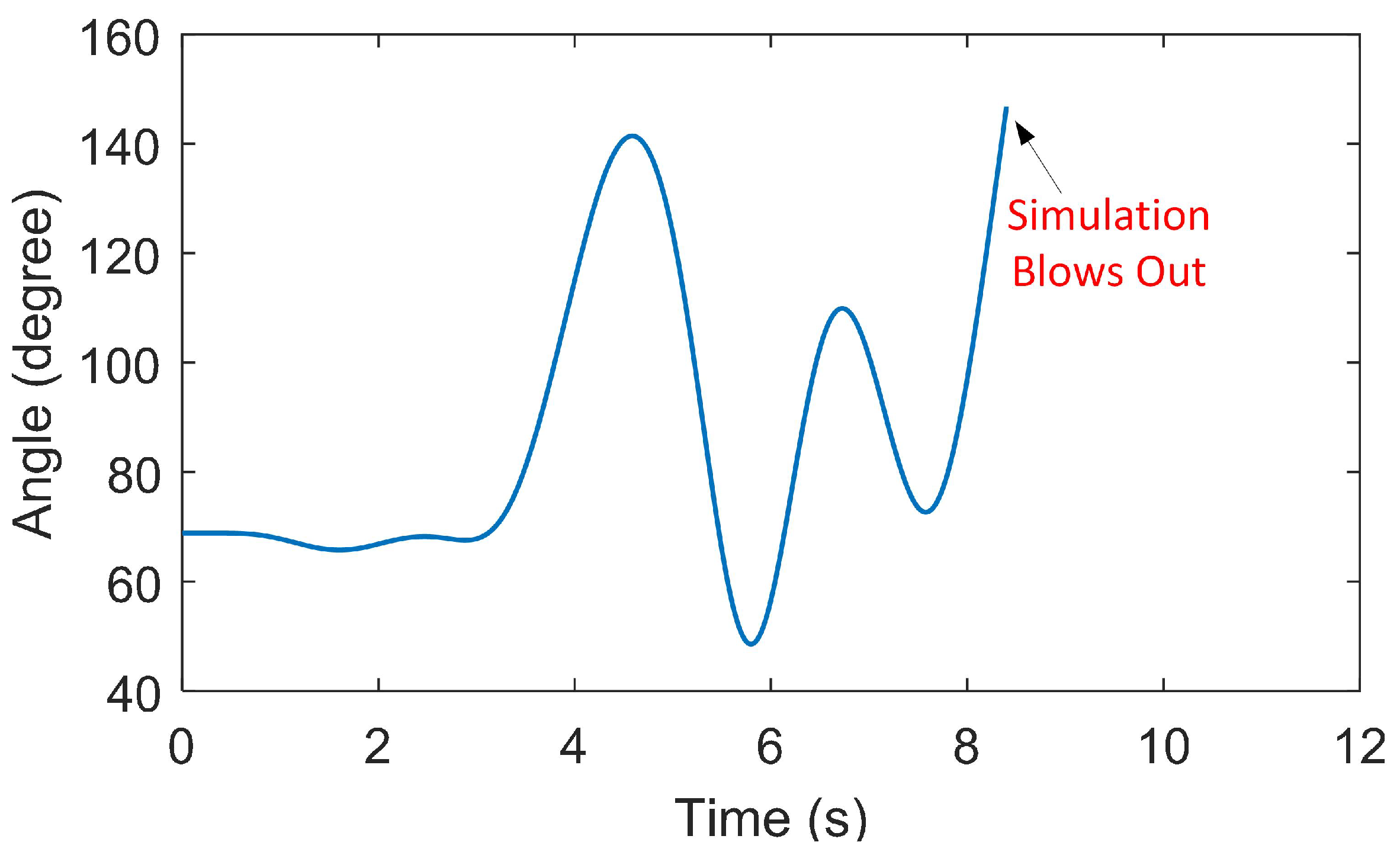
The result of the machine 5–10 angle differences under this replay attack is shown in Figure 10. Although there is no fault event in the system, the replayed data cause large frequency differences between the rectifier and inverter terminals, which changes the transmitted power, triggers forced oscillations in the system and further disturbs the operation of the damping controller. As shown in Figure 10, several oscillation modes are triggered. The replay attack continuously impacts the HVDC damping controller adversely until the simulation blows out. Therefore, the replay attack is able to drive a steady state AC-HVDC system into transient and even adverse power system conditions with recorded data.
5.2.2. Attack Occurs During Transient Events
In this simulation case, the replay attack occurred when large transient events were generated in the AC-HVDC system. Before the simulation of the replay attack, the frequency measurements at the HVDC terminals were recorded in advance when no disturbances existed. Therefore, the frequency difference was zero, and the power modulation on the DC line was also zero. Then, at time 1.0 s, a temporary three-phase fault happens on Lines 21–16, and it is tripped 1.5 cycles later. The fault is cleared another two cycles later, and the line is reconnected. The HVDC terminal frequency during this large transient event should be deviating from the nominal value, which further generates modulation signals that drive the HVDC to damp the oscillations. However, the replay attack is applied when the fault occurs and the recorded steady-state frequency data are sent to the HVDC controller, disabling the oscillation damping capability.
The result of the machine 5–8 angle differences under this replay attack is shown in Figure 11. The black curve shows the expected angle difference if the replay attack is not applied and the HVDC damping controller is operating normally. It is found that the HVDC controller could effectively damp the oscillations and drive the system back to the steady state quickly. However, when the replay attack is applied and the HVDC damping controller is disabled, the large oscillations cannot be damped effectively. Therefore, the replay attack is able to disable the HVDC damping capability and adversely impact the system stability with the recorded steady state data.
5.3. FDIA Attack Results
In this simulation case, the AC-HVDC system is operating normally, and there is no fault event. At time 0.8 s, an FDIA is applied to the HVDC damping controller with injected false data. The injected false data fool the controller and make it think the frequency difference between the rectifier and inverter is very large. The damping controller reacts to the false input and changes the transmitted power, which triggers the inter-area oscillation in the system.
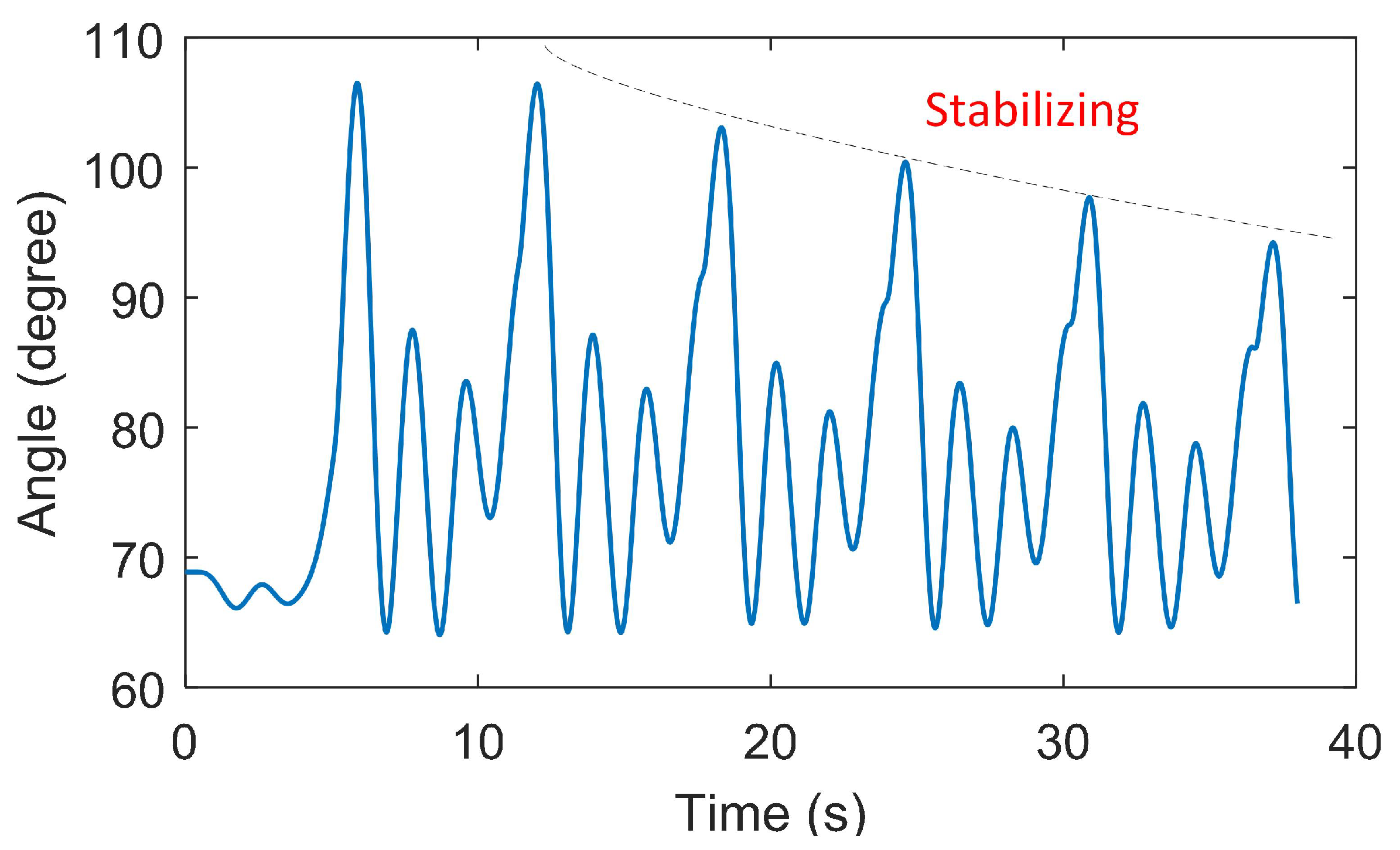
The results of the FDIA depend on the attack plan, the attacker’s knowledge of the power system and the number of sensors that can be compromised. Figure 12 shows the machine 5–10 angle differences for a moderate FDIA situation, where only limited sensors were compromised. A large oscillation is generated by the FDIA, and several oscillation modes are triggered. However, the HVDC damping controller is able to gradually stabilize the system with the trends shown in Figure 12. This means the HVDC damping controller can withstand a certain level of FDIA attacks. The result of a more severe FDIA is shown in Figure 13, in which more sensors were compromised. As a consequence, severe oscillations are generated, and the system loses its stability. Therefore, the FDIA is able to affect the stability of the AC-HVDC system adversely and drive a steady state system into a large oscillation or an unstable situation.
6. Conclusions
This paper has described three kinds of cyber attacks: timing attack, replay attack and FDIA. The impact of cyber attacks on the HVDC oscillation damping control has been studied through simulations conducted on a modified IEEE 39-Bus AC-HVDC system. Results have shown that a timing attack would affect the system only during transient events, while the replay attack and FDIA are both able to adversely affect the system regardless of its operating status. The HVDC damping controller has been proven to be able to withstand low level cyber-attacks with certain robustness. However, with the necessary knowledge of the power system and careful attack plans, the malicious party could hack the power system and drive it into a large oscillation or unstable situations.
Future work includes the development of mitigation methods against cyber attacks on the AC-HVDC system, such as attack-detection algorithms and robust control schemes. More research will be performed regarding the application of cyber attacks to more HVDC lines and larger systems, as well as the design of benchmark test systems.
Author Contributions
R.F. and J.L. performed the simulations and prepared the manuscript. K.K. designed the attack models and provided the analysis of the results. M.E. reviewed conventional HVDC damping controllers and corrected the paper. All authors read and approved the submission.
Acknowledgments
The work presented in the paper has been supported by the DOE Grid Modernization Lab Consortium GLMC0073 project. The support is greatly appreciated.
Conflicts of Interest
The authors declare no conflicts of interest.
Nomenclature
| DC line resistance | |
| DC line inductance | |
| DC line capacitance | |
| DC voltage | |
| voltage at the rectifier | |
| voltage at the inverter | |
| DC current at the rectifier | |
| DC current at the inverter | |
| AC active power at the HVDC terminal | |
| AC reactive power at the HVDC terminal | |
| rectifier firing angle | |
| inverter extinction angle | |
| feedback signal for HVDC power modulation | |
| frequency at the rectifier terminal | |
| frequency at the inverter terminal | |
| K | proportional gain for the damping controller |
| valid data received during period T | |
| instantaneous valid data received at time t | |
| instantaneous corrupted data at time t | |
| T | time period between and |
| M | indicator function |
| z | measurement from sensors |
| x | system states |
| e | measurement errors |
| H | Jacobian matrix of the system |
| W | diagonal weight matrix |
| variance of the measurement errors associated with the i-th meter | |
| solution of the WLS optimization problem | |
| threshold for the largest normalized residual | |
| compromised measurements | |
| false system states | |
| difference between compromised and true measurements | |
| difference between false states and true states | |
| largest normalized residual | |
| largest normalized residual under FDIA | |
| perturbed system states for small-signal stability studies | |
| v | vector of the network bus voltages |
| current injection into the network | |
| prefix representing perturbed value | |
| system coefficient matrices | |
| admittance matrix of the system | |
| state matrix of the system |
References
- Bahrman, M.P.; Johnson, B.K. The ABCs of HVDC transmission technologies. IEEE Power Energy Mag. 2007, 5, 32–44. [Google Scholar] [CrossRef]
- Smed, T.; Andersson, G. Utilizing HVDC to damp power oscillations. IEEE Trans. Power Deliv. 1993, 8, 620–627. [Google Scholar] [CrossRef]
- Guo, J.; Han, Y.; Guo, C.; Lou, F.; Wang, Y. Modeling and vulnerability analysis of cyber-physical power systems considering network topology and power flow properties. Energies 2017, 10, 87. [Google Scholar] [CrossRef]
- Meliopoulos, A.P.S.; Cokkinides, G.; Fan, R.; Sun, L. Data Attack Detection and Command Authentication via Cyber-Physical Comodeling. IEEE Des. Test 2017, 34, 34–43. [Google Scholar] [CrossRef]
- Dougherty, J.J.; Hillesland, T. Power System Stability Considerations with Dynamically Responsive DC Transmission Lines. IEEE Trans. Power Appar. Syst. 1970, PAS-89, 34–45. [Google Scholar] [CrossRef]
- Grund, C.; Hauer, J.; Crane, L.; Carlson, D.; Wright, S. Square Butte HVDC modulation system field tests. IEEE Trans. Power Deliv. 1990, 5, 351–357. [Google Scholar] [CrossRef]
- Cresap, R.; Mittelstadt, W.; Scott, D.; Taylor, C. Operating experience with modulation of the Pacific HVDC intertie. IEEE Trans. Power Appar. Syst. 1978, 4, 1053–1059. [Google Scholar] [CrossRef]
- Long, W.; Nilsson, S. HVDC transmission: yesterday and today. IEEE Power Energy Mag. 2007, 5, 22–31. [Google Scholar] [CrossRef]
- Hossain, E.; Perez, R.; Nasiri, A.; Bayindir, R. Development of lyapunov redesign controller for microgrids with constant power loads. Renew. Energy Focus 2017, 19, 49–62. [Google Scholar] [CrossRef]
- Azad, S.P.; Iravani, R.; Tate, J.E. Damping Inter-Area Oscillations Based on a Model Predictive Control (MPC) HVDC Supplementary Controller. IEEE Trans. Power Syst. 2013, 28, 3174–3183. [Google Scholar] [CrossRef]
- Roberson, D.; O’Brien, J.F. Loop Shaping of a Wide-Area Damping Controller Using HVDC. IEEE Trans. Power Syst. 2017, 32, 2354–2361. [Google Scholar] [CrossRef]
- Pipelzadeh, Y.; Chaudhuri, N.R.; Chaudhuri, B.; Green, T.C. Coordinated Control of Offshore Wind Farm and Onshore HVDC Converter for Effective Power Oscillation Damping. IEEE Trans. Power Syst. 2017, 32, 1860–1872. [Google Scholar] [CrossRef]
- Fan, R.; Sun, L.; Tan, Z. Linear Quadratic Control of SSSC to Increase Power Oscillations Damping of HVDC-AC Power System. In Proceedings of the IEEE Power Energy Society General Meeting, Denver, CO, USA, 26–30 July 2015; pp. 1–5. [Google Scholar]
- Li, Y.; Rehtanz, C.; Ruberg, S.; Luo, L.; Cao, Y. Wide-area robust coordination approach of HVDC and FACTS controllers for damping multiple interarea oscillations. IEEE Trans. Power Deliv. 2012, 27, 1096–1105. [Google Scholar] [CrossRef]
- Meliopoulos, S.; Cokkinides, G.; Fan, R.; Sun, L.; Cui, B. Command Authentication via Faster than Real Time Simulation. In Proceedings of the IEEE Power and Energy Society General Meeting (PESGM), Boston, MA, USA, 17–21 July 2016; pp. 1–5. [Google Scholar]
- AFTER. AFTER Publishable Report. Available online: http://afterproject.eu/wp-content/uploads/2014/07/AFTER-Publishable-report.pdf (accessed on 1 July 2014).
- Netkachov, O.; Popov, P.; Salako, K. Quantification of the impact of cyber attack in critical infrastructures. In International Conference on Computer Safety, Reliability, and Security; Springer: Berlin/Heidelberg, Germany, 2014; pp. 316–327. [Google Scholar]
- Tøndel, I.A.; Mostue, B.A.; Jaatun, M.G.; Kjølle, G. Towards improved understanding and holistic management of the cyber security challenges in power transmission systems. In International Conference on Availability, Reliability, and Security; Springer: Berlin/Heidelberg, Germany, 2013; pp. 240–255. [Google Scholar]
- Fan, X.; Du, L.; Duan, D. Synchrophasor Data Correction under GPS Spoofing Attack: A State Estimation Based Approach. IEEE Trans. Smart Grid 2017, PP, 1. [Google Scholar] [CrossRef]
- Fu, R.; Huang, X.; Sun, J.; Zhou, Z.; Chen, D.; Wu, Y. Stability analysis of the cyber physical microgrid system under the intermittent DoS attacks. Energies 2017, 10, 680. [Google Scholar] [CrossRef]
- Mo, Y.; Sinopoli, B. Secure Control Against Replay Attacks. In Proceedings of the 47th Annual Allerton Conference on Communication, Control, and Computing (Allerton), Monticello, IL, USA, 30 September–2 October 2009; pp. 911–918. [Google Scholar]
- Zhu, S.; Setia, S.; Jajodia, S.; Ning, P. An Interleaved Hop-by-Hop Authentication Scheme for Filtering of Injected False Data in Sensor Networks. In Proceedings of the IEEE Symposium on Security and Privacy, Berkeley, CA, USA, 9–12 May 2004; pp. 259–271. [Google Scholar]
- Ashok, A.; Govindarasu, M.; Wang, J. Cyber-Physical Attack-Resilient Wide-Area Monitoring, Protection, and Control for the Power Grid. Proc. IEEE 2017, 105, 1389–1407. [Google Scholar] [CrossRef]
- Sridhar, S.; Hahn, A.; Govindarasu, M. Cyber–physical system security for the electric power grid. Proc. IEEE 2012, 100, 210–224. [Google Scholar] [CrossRef]
- He, H.; Yan, J. Cyber-physical attacks and defences in the smart grid: a survey. IET Cyber Phys. Syst. Theory Appl. 2016, 1, 13–27. [Google Scholar] [CrossRef]
- Bahrami, S.; Toulabi, M.; Ranjbar, S.; Moeini-Aghtaie, M.; Ranjbar, A.M. A Decentralized Energy Management Framework for Energy Hubs in Dynamic Pricing Markets. IEEE Trans. Smart Grid 2017. [Google Scholar] [CrossRef]
- Mohammadi, A.; Mehrtash, M.; Kargarian, A. Diagonal quadratic approximation for decentralized collaborative TSO+ DSO optimal power flow. IEEE Trans. Smart Grid 2018. [Google Scholar] [CrossRef]
- Sheikhi, A.; Rayati, M.; Bahrami, S.; Ranjbar, A.M.; Sattari, S. A cloud computing framework on demand side management game in smart energy hubs. Int. J. Elect. Power Energy Syst. 2015, 64, 1007–1016. [Google Scholar] [CrossRef]
- Beg, O.A.; Johnson, T.T.; Davoudi, A. Detection of False-Data Injection Attacks in Cyber-Physical DC Microgrids. IEEE Trans. Ind. Inf. 2017, 13, 2693–2703. [Google Scholar] [CrossRef]
- Zhong, X.; Yu, L.; Brooks, R.; Venayagamoorthy, G.K. Cyber Security in Smart DC Microgrid Operations. In Proceedings of the IEEE 1st International Conference on DC Microgrids (ICDCM), Atlanta, GA, USA, 27–29 June 2015; pp. 86–91. [Google Scholar]
- Mantooth, H.A.; Liu, Y.; Farnell, C.; Zhang, F.; Li, Q.; Di, J. Securing DC and Hybrid Microgrids. In Proceedings of the IEEE 1st International Conference on DC Microgrids (ICDCM), Atlanta, GA, USA, 27–29 June 2015; pp. 285–286. [Google Scholar]
- Ni, Y.X.; Fouad, A. A simplified two-terminal HVDC model and its use in direct transient stability assessment. IEEE Trans. Power Syst. 1987, 2, 1006–1012. [Google Scholar] [CrossRef]
- Trudnowski, D.; Kosterev, D.; Undrill, J. PDCI Damping Control Analysis for the Western North American Power System. In Proceedings of the IEEE Power Energy Society General Meeting, San Diego, CA, USA, 21–25 July 2013; pp. 1–5. [Google Scholar]
- Fan, R.; Elizondo, M.; Kirkham, H.; Lian, J.; Wilches-Bernal, F.; Schoenwald, D. Oscillation Damping Control Using Multiple High Voltage DC Transmission Lines: Controllability Exploration. In Proceedings of the IEEE/PES Transmission and Distribution Conference and Exposition, Denver, CO, USA, 16–19 April 2018. [Google Scholar]
- Kocher, P.C. Timing attacks on implementations of Diffie-Hellman, RSA, DSS, and other systems. In Annual International Cryptology Conference; Springer: Berlin/Heidelberg, Germany, 1996; pp. 104–113. [Google Scholar]
- Andrade, S.B.; Pignati, M.; Dan, G.; Paolone, M.; Boudec, J.Y.L. Undetectable PMU Timing-Attack on Linear State-Estimation by Using Rank-1 Approximation. IEEE Trans. Smart Grid 2017, PP, 1. [Google Scholar]
- Amini, M.; Ilić, M.D.; Karabasoglu, O. DC power flow estimation utilizing bayesian-based LMMSE estimator. In Proceedings of the Power & Energy Society General Meeting, Denver, CO, USA, 26–30 July 2015; pp. 1–5. [Google Scholar]
- Meliopoulos, A.P.S.; Cokkinides, G.J.; Myrda, P.; Liu, Y.; Fan, R.; Sun, L.; Huang, R.; Tan, Z. Dynamic State Estimation-Based Protection: Status and Promise. IEEE Trans. Power Deliv. 2017, 32, 320–330. [Google Scholar] [CrossRef]
- Kundur, P.; Rogers, G.; Wong, D.; Wang, L.; Lauby, M. A comprehensive computer program package for small signal stability analysis of power systems. IEEE Trans. Power Syst. 1990, 5, 1076–1083. [Google Scholar] [CrossRef]
Figure 1.
Overview of a two-terminal line commutated converter (LCC)-HVDC system.

Figure 2.
Typical Conventional HVDC damping controller based on the frequency difference.
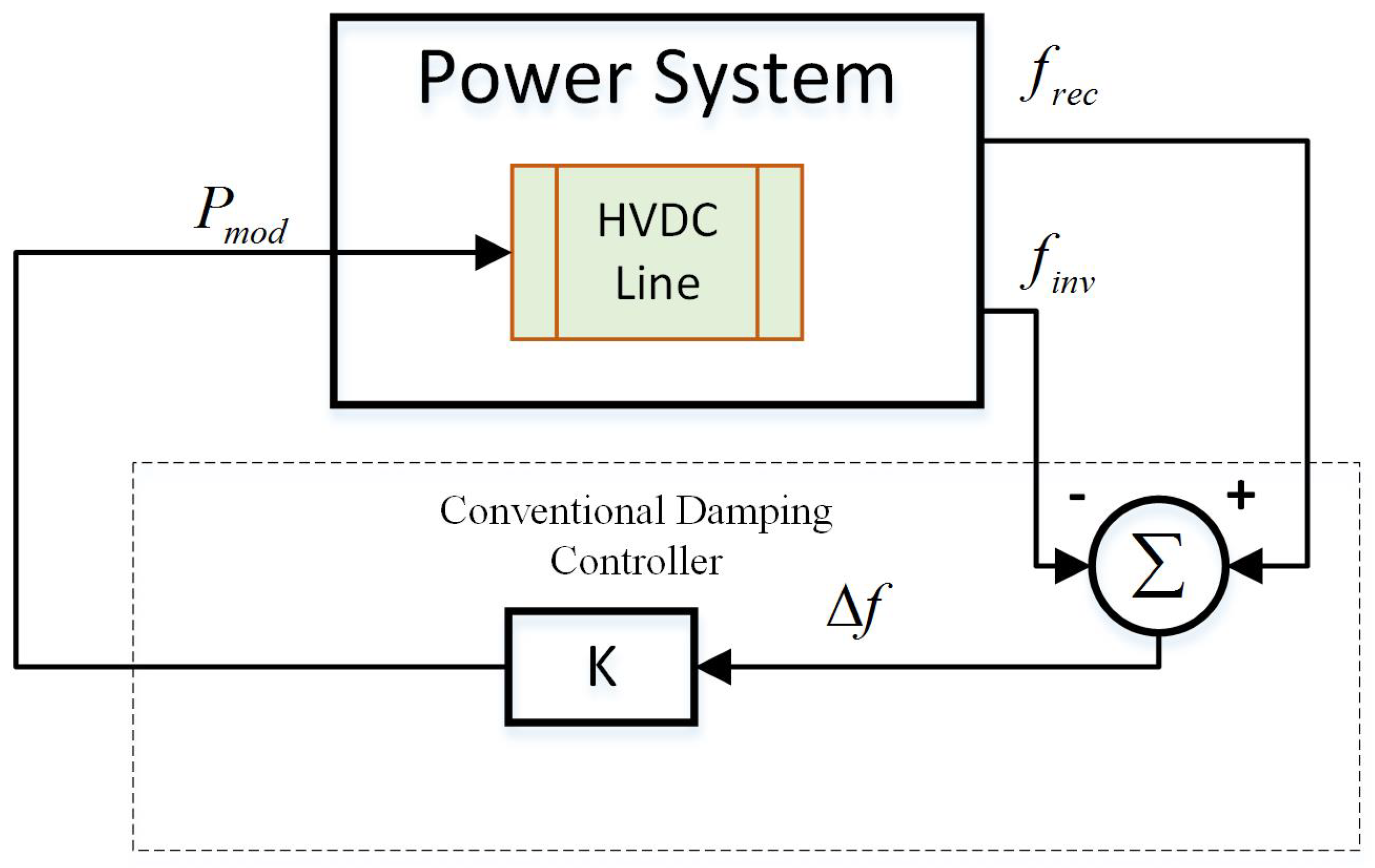
Figure 3.
Principle of a timing attack on the HVDC damping controller.
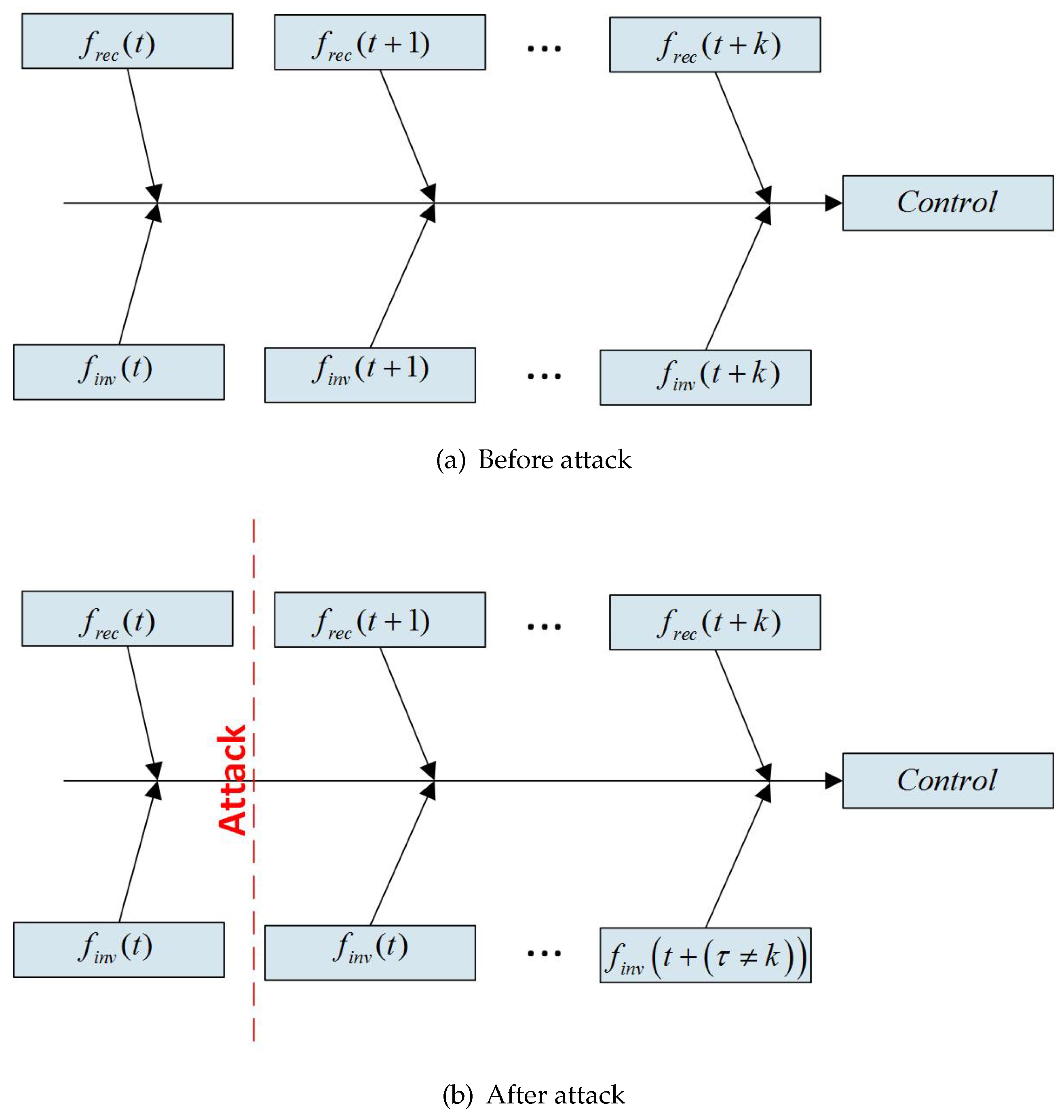
Figure 4.
Principle of a replay attack on an HVDC damping controller.
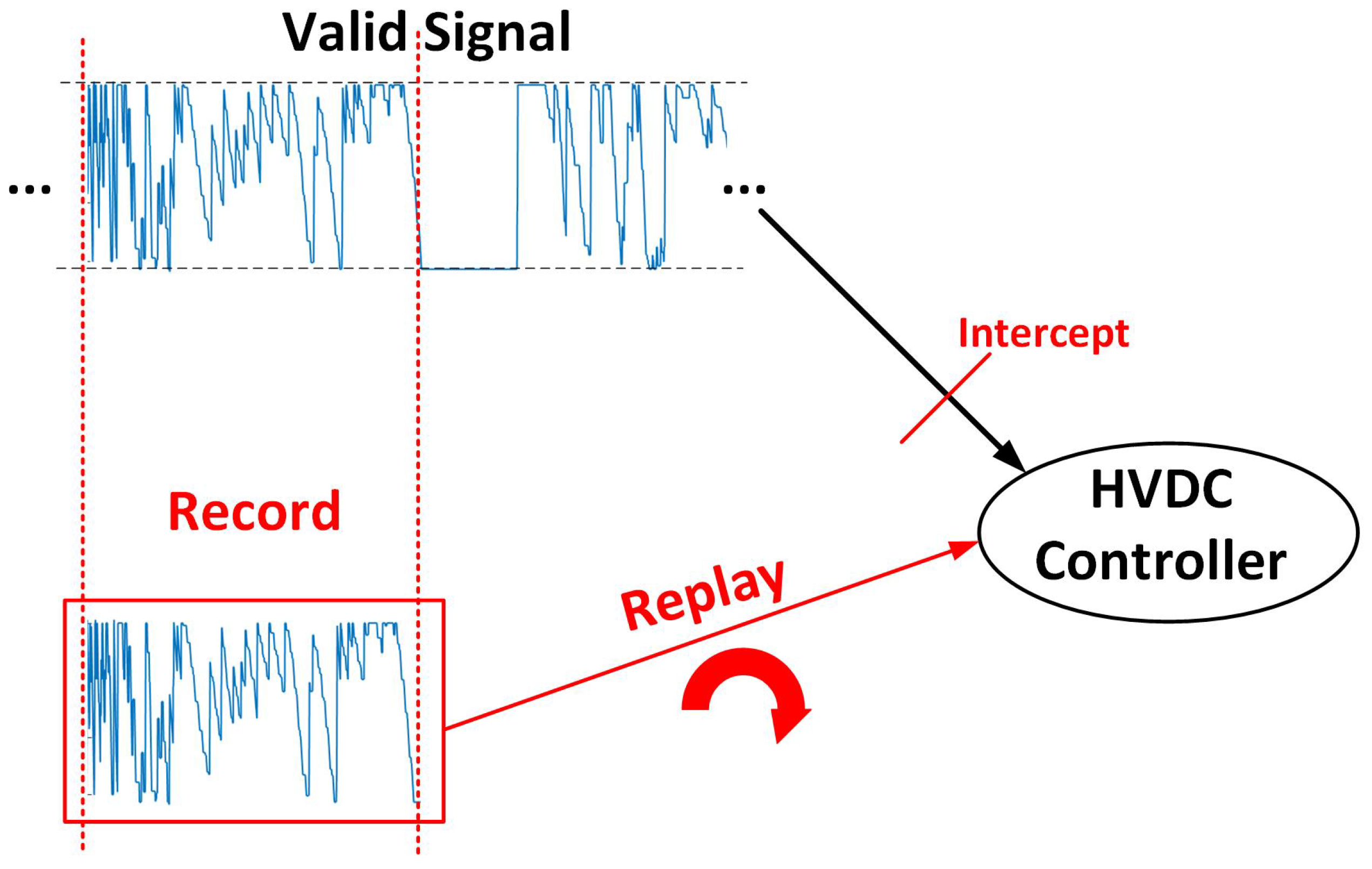
Figure 5.
Modified New England IEEE 39-Bus system with HVDC link.
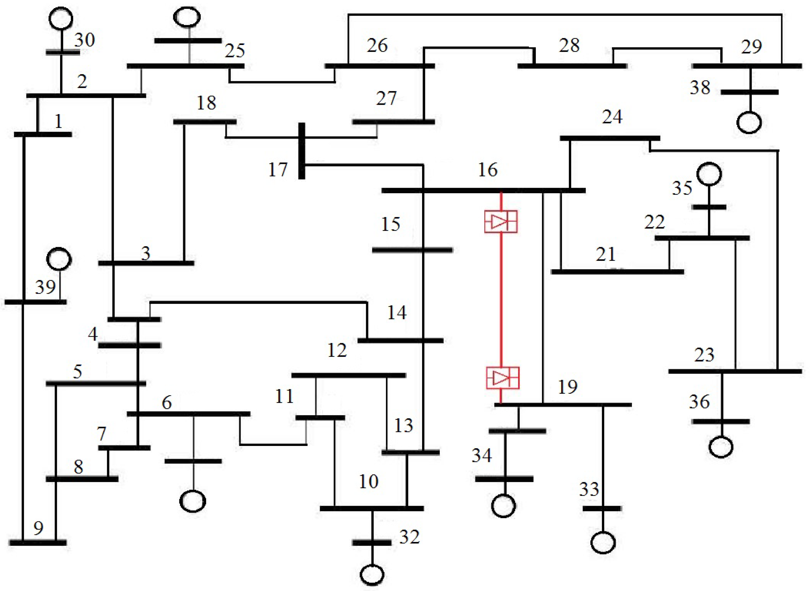
Figure 6.
A schematic overview of cyber attacks on the HVDC damping controller. FDIA, false data injection attack.
Figure 6.
A schematic overview of cyber attacks on the HVDC damping controller. FDIA, false data injection attack.
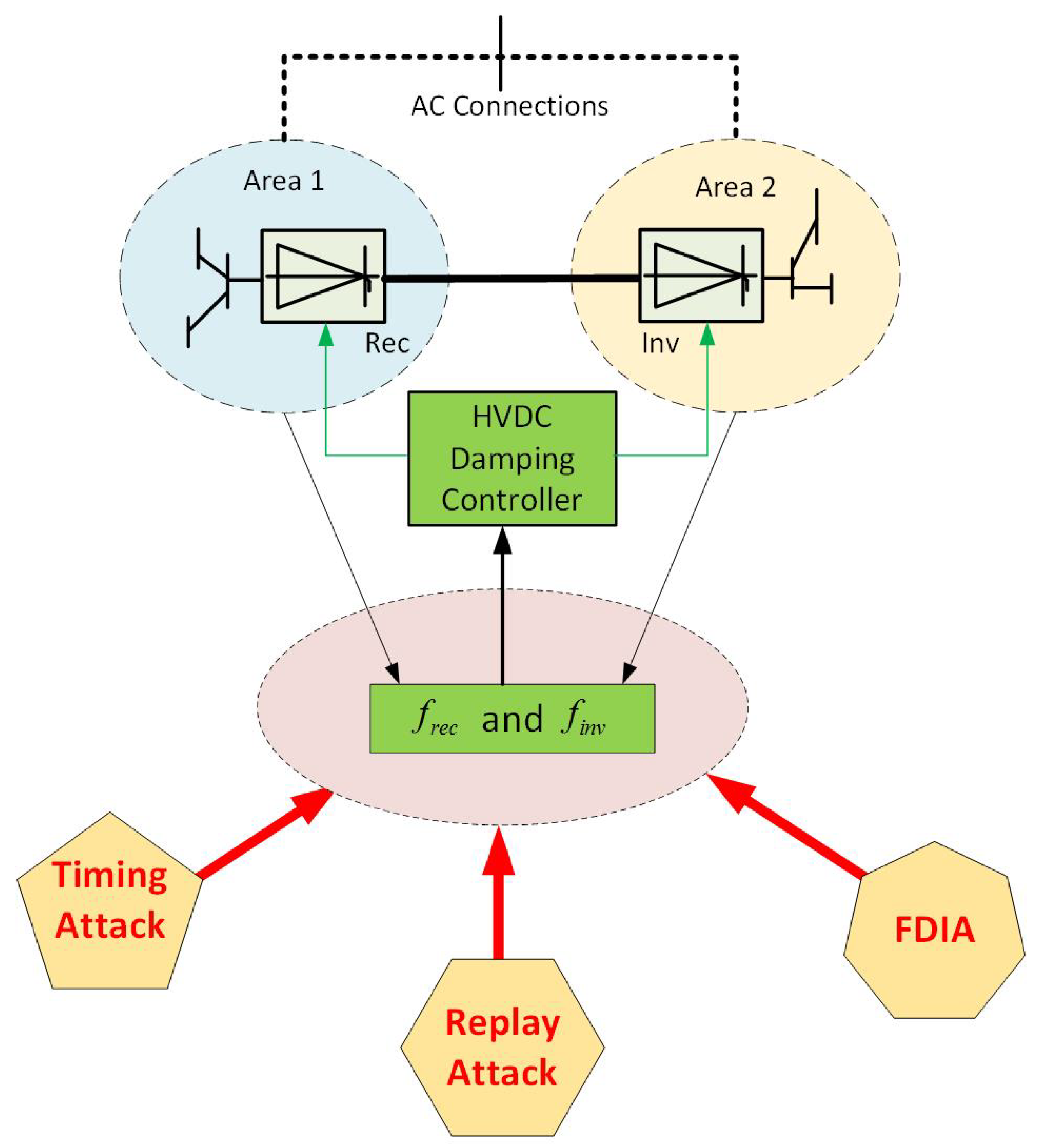
Figure 7.
Bus 23 voltage magnitude with different timing attacks.

Figure 8.
Machine 5–10 angle differences with different timing attacks.
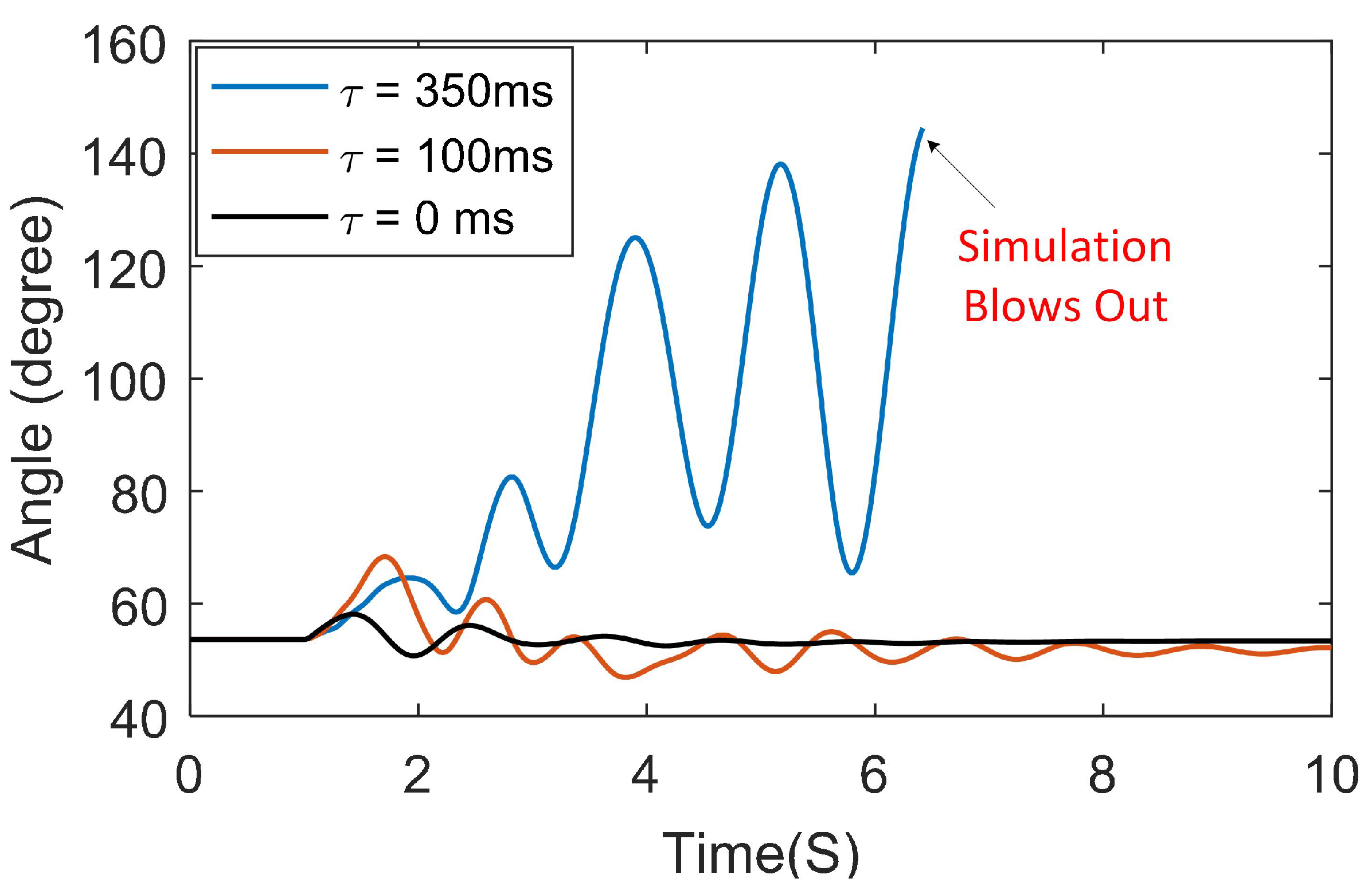
Figure 9.
Original recorded data and replayed signals.

Figure 10.
Machine 5–10 angle differences under the replay attack.

Figure 11.
Machine 5–8 angle differences under the replay attack.
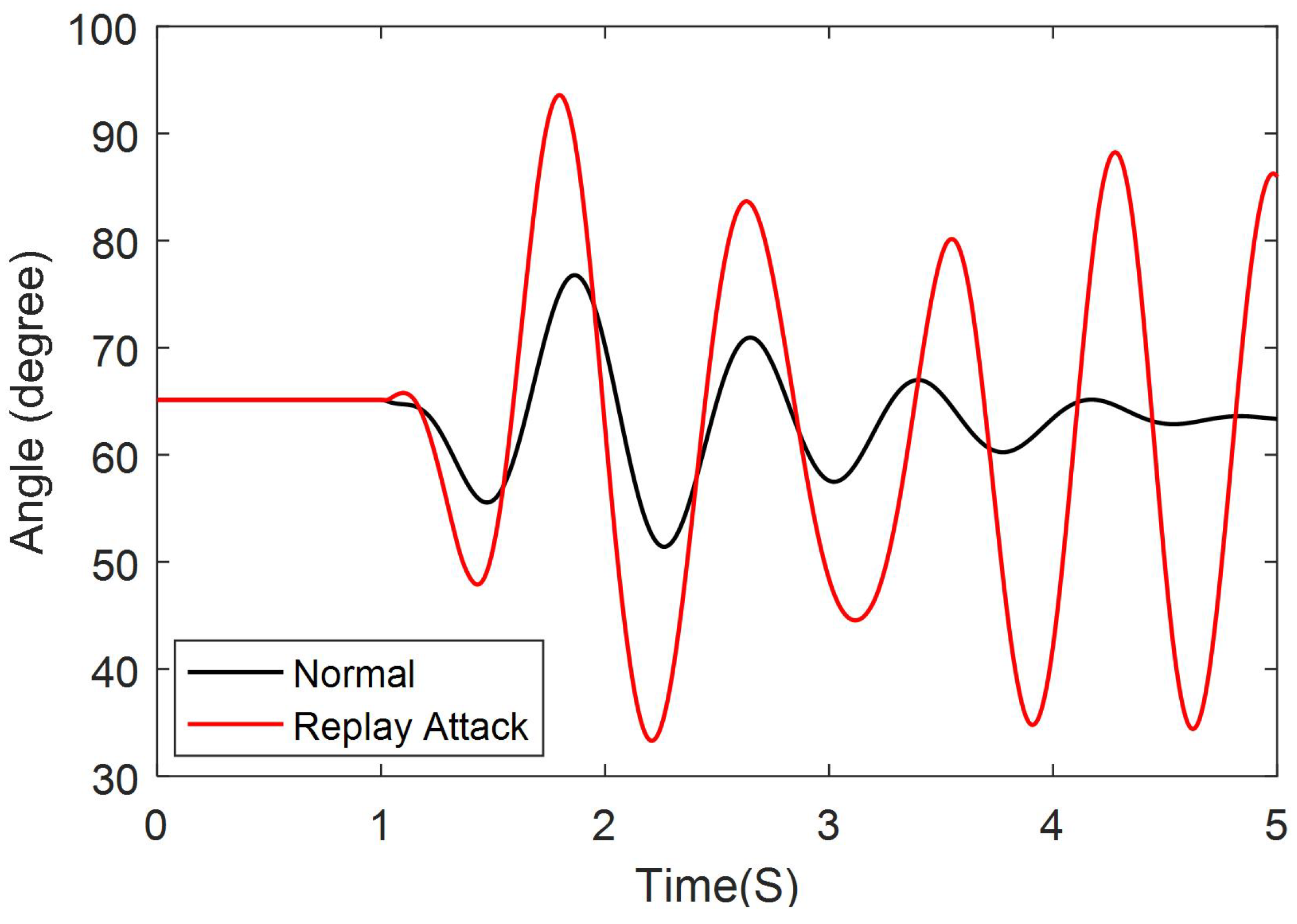
Figure 12.
Machine 5–10 angle differences under a moderate FDIA.

Figure 13.
Machine 5–10 Machine angle differences for a severe FDIA.


Table 1.
Oscillation modes of the test system.
| Mode | Frequency (Hz) | Damping Ratio (%) |
|---|---|---|
| 1 | 0.231 | 4.47 |
| 2 | 0.552 | 2.83 |
| 3 | 0.781 | 3.56 |
© 2018 by the authors. Licensee MDPI, Basel, Switzerland. This article is an open access article distributed under the terms and conditions of the Creative Commons Attribution (CC BY) license (http://creativecommons.org/licenses/by/4.0/).
Share and Cite
MDPI and ACS Style
Fan, R.; Lian, J.; Kalsi, K.; Elizondo, M.A. Impact of Cyber Attacks on High Voltage DC Transmission Damping Control. Energies 2018, 11, 1046. https://doi.org/10.3390/en11051046
AMA Style
Fan R, Lian J, Kalsi K, Elizondo MA. Impact of Cyber Attacks on High Voltage DC Transmission Damping Control. Energies. 2018; 11(5):1046. https://doi.org/10.3390/en11051046
Chicago/Turabian StyleFan, Rui, Jianming Lian, Karanjit Kalsi, and Marcelo A. Elizondo. 2018. "Impact of Cyber Attacks on High Voltage DC Transmission Damping Control" Energies 11, no. 5: 1046. https://doi.org/10.3390/en11051046
Note that from the first issue of 2016, this journal uses article numbers instead of page numbers. See further details here.