Article

Virtual Inertia Adaptive Control of a Doubly Fed Induction Generator (DFIG) Wind Power System with Hydrogen Energy Storage

1
Faculty of Electronic Information and Electrical Engineering, Dalian University of Technology, Dalian 116024, China
2
State Grid Tongling Power Supply Company, Tongling 244000, China
3
School of Engineering & Applied Science, Aston University, Birmingham, Birmingham B4 7ET, UK
4
State Grid Xinjiang Electric Power Corporation, Urumqi 830002, China
*
Author to whom correspondence should be addressed.
Energies 2018, 11(4), 904; https://doi.org/10.3390/en11040904
Submission received: 31 March 2018 / Revised: 31 March 2018 / Accepted: 10 April 2018 / Published: 12 April 2018
(This article belongs to the Special Issue Wind Turbine Loads and Wind Plant Performance)

Abstract

:
This paper presents a doubly fed induction generator (DFIG) wind power system with hydrogen energy storage, with a focus on its virtual inertia adaptive control. Conventionally, a synchronous generator has a large inertia from its rotating rotor, and thus its kinetic energy can be used to damp out fluctuations from the grid. However, DFIGs do not provide such a mechanism as their rotor is disconnected with the power grid, owing to the use of back-to-back power converters between the two. In this paper, a hydrogen energy storage system is utilized to provide a virtual inertia so as to dampen the disturbances and support the grid’s stability. An analytical model is developed based on experimental data and test results show that: (1) the proposed method is effective in supporting the grid frequency; (2) the maximum power point tracking is achieved by implementing this proposed system; and, (3) the DFIG efficiency is improved. The developed system is technically viable and can be applied to medium and large wind power systems. The hydrogen energy storage is a clean and environmental-friendly technology, and can increase the renewable energy penetration in the power network.

1. Introduction

Wind energy is one of the most economical and mature renewable energy to be utilized in large quantities. With the ever-increasing grid-connected capacity of wind power generation, electrical generator technologies are significantly developed, including doubly fed induction generator (DFIGs) and permanent magnet synchronous generators (PMSGs). However, there are a variety of challenges and opportunities, such as the safety and stability issues of wind power systems, especially for grid-tied systems [1].
In order to minimize the influence of the frequency discontinuity on the power system, conventional synchronous generators can adjust the rotor speed by changing the power tracking control strategy. In this circumstance, the rotor kinetic energy plays a role, DFIGs can achieve maximum wind energy capture by using the rotor side converter. However, there does not exist a relationship between the speed of the wind turbine and the frequency of the electrical grid. The existing control strategy of the wind turbine does not respond to the change in the power grid frequency. Thus, it is difficult to contribute to the inertia of the wind turbines [2,3]. To improve the inertia of wind turbine generators, several control methods have been reported, including the droop control, rotational speed control, pitch angle control, coordinate control, and so on [4,5,6,7]. For example, an active power control method of the wind turbine generator is required to adjust the active power at output [8]. In general, the generator in controlled to track the changing frequency of the power system based on the droop curve between the given electromagnetic torque of the generator and the system frequency. However, the control strategy is difficult to operate effectively at low wind speeds and high wind speeds [4]. The rotational speed of a wind turbine generator is directly controlled, which can regulate the transient power of frequency modulation in order to ensure the safe operation [5]. The optimization algorithm is used to adjust the pitch angle of the wind turbine, which operates the machine at high speeds, regardless of the change in the frequency of the power grid. In this case, those control methods increase not only the inertia of the wind turbine generators but also its reliability during the frequency fluctuations. Due to the slow response of the pitch angle control in wind turbines, it is also difficult to accommodate large fluctuations of the frequency within a short period of time [6]. Furthermore, the difference in the rotor’s kinetic energy between wind turbines can lead to different performance with frequency modulation during a load disturbance. Thus, a coordinating virtual inertia control strategy of each unique generator is needed [7]. The existing control strategies can achieve the maximum power point tracking for the wind turbine generators, but suffer from low efficiency and complicated control systems.
With the rapid development of energy storage technologies, energy storage systems have become an essential part to ensure the reliable power supply of electrical power system [9]. There are many conventional energy storage technologies available, such as water pumped storage [10], compressed-air energy storage [11], flywheel energy storage [12], lead acid batteries [13], lithium-ion battery [14], electrochemical flow cells [15], superconductor energy storage [16], and super capacitor energy storage [17]. In addition, hydrogen storage as a new energy storage technology has been developed in recent years [18,19,20,21]. This technology has advantages, such as high energy density, long service life, low operating cost, cleanness, and environmental friendliness. Furthermore, dynamic response characteristics of hydrogen storage systems are much better than traditional energy storage systems [22,23]. In this study, the hydrogen storage technology is applied to wind turbines for the virtual inertia control of wind farms, while maintaining the original operating state of wind power generators. The hydrogen storage technology can effectively improve the frequency stability of wind turbines, but also to ensure the maximum power point tracking of wind power to enhance the system efficiency of wind turbines.
In this paper, a framework of the hydrogen energy storage coupling wind power system is firstly built. Secondly, the collocation method of hydrogen storage capacity of the coupling system is given, and the proportional-derivative (PD) charge-discharge control strategy based on the fuzzy logic and adaptive control is proposed, which is based on the optimal collocation of hydrogen storage capacity. The validation results and the analysis of the developed system is provided to prove the correctness and feasibility of the virtual inertia control method. The purpose of this paper is to verify the effective inertia support for the hybrid system and to achieve the same effect as the synchronization unit with the frequency modulation.

2. The DFIG System with Hydrogen Energy Storage

The conventional inertia control method adjusts and responds to the changes in system frequency based on kinetic energy of the machine rotor. In this work, the energy storage system is installed across the dc link of wind turbines. A hydrogen energy storage system (HESS) is developed, including a hydrogen production system and a hydrogen-oxygen fuel cell system. The electrolytic cell assembly with a hydrogen production system is equivalent to a charging device, and has a strong adaptability to intermittent wind power availability. The existing commercial products can stabilize the generator system within one millisecond and can work within the rated power range [24,25]. But, the fuel cell for the discharge device of the HESS has some disadvantages such as long starting time and slow dynamic response [
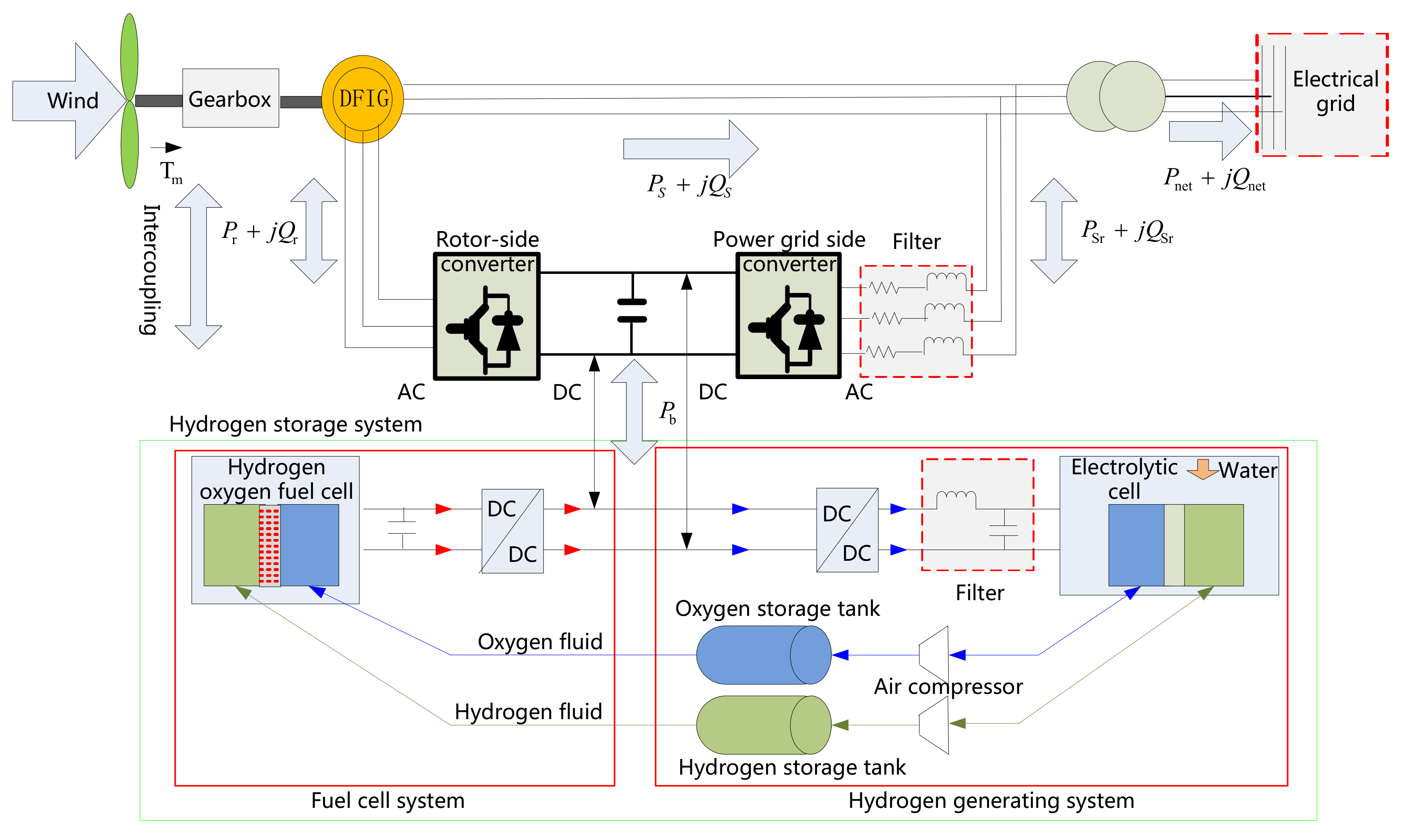
26]. A super-capacitor is then installed in the fuel cell as an energy buffer between the fuel cell and the wind system in the proposed system. This device can quickly release energy during the start-up stage to meet the power demand insufficient wind power or increased load conditions. In the low load scenario, the fuel cell provides electric power to the super-capacitor and load with rapid charging and discharging characteristics to meet the energy demand. A DFIG based wind power system with HESS is proposed in this paper, and the diagram is shown in Figure 1. DFIGs typically operate in two states that are subject to wind speeds, and Figure 1 illustrates the power flow under two operational states. By using the back-to-back converters, DFIGs can adjust the power flow and supply power to the grid with constant frequency. When the wind speed is low, the power converter absorbs power from the grid to establish the magnet field in the generator and the active power can be provided by the HESS. However, when the wind speed is high, the power converter can provide power to the grid. In Figure 1, Ps is the stator power. Pr is the slip power of rotor. PSr is the power that is transferred from the rotor to the electrical grid. Pb is the electrolytic hydrogen power. There are two power unbalance statuses that are considered during the system design. The first status is load changes, such as increased load. In order to maintain the power balance of the electrical grid, the DFIG should be able to deliver energy to the electrical grid through both stator and rotor sides under the DFIG is running the super-synchronization operation state conditions. To reduce the loss of wind energy, some of the energy is transported to the HESS system by the converter to start the hydrogen electrolysis, (Pr is the sum of PSr and Pb). If wind power is low, then the fuel cell of the HESS will deliver electrical power to the system (Pr and Pb will flow into the electrical grid through the grid-side converter). If the wind power is abundant, the active power will flow from the stator and the rotor to the grid (PSr includes Pr and Pb). If the wind power is deficient, then the HESS provides the power to the rotor winding by discharging the fuel cell. In essence, the HESS acts as an energy buffer to balance the power between wind turbines and the grid.

3. System Virtual Inertia Definition and Hydrogen Storage Configuration

In modern electric power systems, the rotor inertia constant H of the synchronous generators can be expressed as
H = E ks S N = J Ω r 2 2 S N
where Eks is the kinetic energy of the rotor at rated speed. J is the rotational inertia of the generator. Ωr is the rated speed of the generator. S N is the rated capacity of the generator. The capability of the rapid power response and the reasonable control strategy of the storage device can make the frequency of the wind farm similar to the inertia response from synchronous generators. The average inertia of the wind energy storage system is a constant within a small period time Δ t , such as the change rate of system frequency is unchanged the symbol [27].
H W F E S S = P Δ t f 2 ( t + Δ t ) f 2 ( t ) = Δ E f 2 ( t + Δ t ) f 2 ( t )
where H W F E S S is the rotor inertia constant of wind farm energy storage system (WFESS); f ( t ) and f ( t + Δ t ) are the per-unit value of system frequency at the time t and   t + Δ t , respectively. P is the per-unit value of the discharge power of the storage system in time Δ t . Δ E is the per-unit value of the extra energy of the electric element that is released time Δ t .
The charging and discharging are two different processes. The charging process is carried out in the hydrogen production subsystem. The discharging process is proceeded in the hydrogen and oxygen fuel cell. The average generalized inertia constant in time Δ t during the charging process is expressed as
H W F H E S S = n F u el t 0 t 0 + Δ t v el d t α el N el [ f 2 ( t + Δ t ) f 2 ( t ) ]
where H W F H E S S is the rotor inertia constant of wind farm hydrogen energy storage system (WFHESS); F is the Faraday constant. n is the mole number per mole of water transfer electrons. N el is the number of electrolytes.
The voltage and the electrolytic efficiency of the electrolytic bath of the system during the charging process can be denoted are given by [25].
N el [ u 0 + r 1 + r 2 T el A i el + ( s 1 + s 2 T el + s 3 T el 2 ) log ( t 1 + t 2 T el + t 3 T el 2 A i el + 1 ) ]
α el = a 1 exp ( a 2 + a 3 T + a 4 T el 2 i el / A + a 5 + a 6 T + a 7 T el 2 ( i el / A ) 2 )
where v el is the hydrogen storing rate of the hydrogen tank for a hydrogen production subsystem. i el is the electrolytic cell current. u 0 is reversible battery voltage that changes with temperature and pressure. r i is the reversible battery voltage that changes with temperature and pressure. s i and t i are the overvoltage parameters on the electrode. a i is the empirical value. A is the area of the electrode. T el is the temperature of the electrolyte. The discharge part of the hydrogen storage system employs the proton exchange membrane fuel cell. The average generalised inertia constant in time Δ t during the discharging process is
H W F H E S S = k n 1 ( n n e a r n s t + u o h m i c u d ) i f Δ t [ f 2 ( t + Δ t ) f 2 ( t ) ]
where i f is the per-unit of the current of the fuel cell. k is the discharging rate of the fuel cell. n 1 is the number of the single fuel cell. n n e a r n s t is the thermodynamic electromotive force of the fuel cell. n o h m i c is the ohmic polarization’s overvoltage. n d is the equivalent overvoltage of the dynamic performance. The thermodynamic electromotive force is also called the ideal battery voltage, it is the actual voltage of the single fuel cell at the open circuit state, which can be expressed as
u n e r n s t = 1.229 8.5 × 10 4 ( T 298.15 ) + 4.3085 × 10 5 T ( ln p H 2 + 0.5 ln p o 2 )
where T is the operating temperature of the fuel cell battery pack. and are the partial pressure of H2 and O2 in the battery pack, respectively. The ohmic polarization’s overvoltage is also called the ohmic droop, which is the voltage drop due to the electrical reactance that is generated by the electrons through the bipolar plate and electrode material. The electrical reactance that is generated by the proton through the proton exchange membrane can be found by
u o h m i c = i f ( z m + z c )
where zm and zc are the equivalent membrane impedance and the impedance of protons through the proton membrane, respectively.
The virtual inertia of the DFIG is mainly related to the input and output energy of the hydrogen storage device. The virtual inertia can improve system stability. But, an unsuitable virtual inertia at different working states may also influence the stability of the system [28,29]. Therefore, the input and output energy of hydrogen energy storage are adjusted and the virtual inertia of the wind farm is optimized, which effectively reduces the adverse impacts of the wind on the stability of the power system frequency.
In this work, the frequency range of the power system is from 48 to 51 Hz, based on the grid operation standard [30]. Thus, the variation range of per-unit value of the generator rotate speed is about from 0.96 to 1.02 p.u. during the frequency modulation. Consequently, the maximum rotor kinetic energy that is absorbed or released by the generator can be defined as
Δ E x max = 1 2 J ( 1.02 2 1 ) Ω r 2 = 0.0404 J Ω r 2
Δ E s max = 1 2 J ( 1 0.96 2 ) Ω r 2 = 0.0392 J Ω r 2
The electrolytic bath of the hydrogen storage system in time Δ t is assumed that it absorbs the same energy as the generator when the frequency fluctuates. That is
P E Δ t = 0.0404 J Ω r 2 = 0.0404 P N T J
When considering the frequency control, the response time is about 10 s. This may be long in the control’s perspective, but is shorter than other wind turbines [31]. The inertia time constant is assumed to be the same as the synchronous generator, that is Δ t = T J . Thus, the power capacity of the electrolytic bath is expressed
P E = 0.0404 P N
where P N and T J are the rated power and the inertia time constant of generator, respectively. To simplify the calculation, P E is the average value of the power capacity of the electrolytic bath in time Δ t . To meet the demand of the system virtual inertia control in practical application, the power of the electrolytic bath can be increased when the frequency rises. When the frequency reduces, the proton exchange membrane fuel cell (PEMFC) device of a hydrogen storage system releases the same energy as the synchronous generator in time Δ t . There are Equations (13) and (14):
P F Δ t = 0.0392 J ω S 2 = 0.0392 P N T J
P F = 0.0392 P N
where P F is the output power.
The difference between Emax and Emin is equal to the energy stored in a storage tank full of gas. Hence, the capacity of hydrogen storage tank can be seen
V H = | E max E min | / 3
In general, the system can provide 3 kWh electric energy hydrogen with 1 Nm3 the volume in standard conditions, as shown in the Equation (15) [32]. The operation time of the system and the corresponding control strategy are considered to calculate the volume at the actual case. The capacity of the oxygen storage tank is a half of the hydrogen storage tanks, based on the chemical formula for hydrogen and oxygen combustion. In addition, the capacity of storage tanks can be increased to improve the system reliability. Hence, the charging-discharging time of the hydrogen storage system is longer than the response time of the traditional generators.
When it meets the power requirements, it also can satisfy the energy requirements. When the capacity margin and the efficiency of the hydrogen storage system are considered, if the total power of the HESS is about 5% of the wind turbine rated power, the wind farm can generate the similar virtual inertia of the synchronous generators.

4. Adaptive Control of the Virtual Inertia of the Auxiliary System of the HESS

The virtual inertia definition of the DFIG with energy storage system has been carried out in the previous part. The PD charge-discharge control strategy based on the fuzzy logic and adaptive control is developed to improve the performance and the efficiency in the following part.

4.1. Virtual Inertial Control Model Containing the Hydrogen Storage System

The unbalance between the input and output energy of the system is the main reason why the system frequency changes. In this circumstance, the synchronous generator needs to change the rotational speed and absorb or release the kinetic energy of the rotor to restrain the unbalanced energy from the power system [28]. The proposed system controls the active power output of HESS, which improves the virtual inertia of system, avoids the unbalance energy, and reduces the damped system frequency mutation. By implementing the proposed energy storage system, the system frequency is able to keep within the normal range.
Figure 2 shows a diagram of the virtual inertial control in a developed energy storage system. The proposed system can release the same energy with a similar inertial time constant by comparing with the inertial effect of the synchronous generator. Thus, the designed system generates the same virtual inertia response as the same capacity synchronous generator.
Here, PL is the interaction power between the load and electrical grid. PG is the power of the traditional synchronous unit, which feeds into the electrical grid. PT is the interaction power to the electrical grid. Pp is the frequency modulation power of the traditional generator. PS is the power that the wind power system feeds into the electrical grid. Pf is the output power in DC part of the middle of HESS. H is the virtually inertial constant of the system. D is the system damping. fgrid and Vgrid, respectively, are the frequency and voltage of the electrical grid. When the active power of the system is balanced, then the output power of HESS is equal to zero, and the balance equation can be expressed as
P G + P S + P T P L = Δ P = 0
The random fluctuation of the output power of wind power unit and the switch of load may influence the Equation (16), which the active power balance of system is affected and appears as the frequency difference of the system. The relation between the deviation value of power ΔP and the variation of frequency Δf is depicted as
2 H d Δ f dt = Δ P D Δ f = P G + P S + P T P L D Δ f
The constant voltage charging mode is used in the HESS, given per-unit value of current is i f , as can be seen in the Equation (18).
i f = k p Δ f + k d d Δ f dt
The transformer loss and the response time of the HESS are ignored to gain the relation between the virtual inertial constant and the virtual inertial control parameter, and the equation is described as
( 2 H + u f k d ) 2 d Δ f d t = P G + P S + P T P L ( D + k p u f ) 2 Δ f
where the u f is the charging voltage.
When the proportionality coefficient kp and the differential coefficient kd are positive, then the virtual inertia of the system will increase, which is helpful in dampening the frequency discontinuity of the power system. However, the increasing of the virtual inertia has less impact on maintaining the frequency of the electrical grid at a certain constant, such as 50 Hz. For example, when the frequency of the electrical grid once restores, the continual increasing virtual inertia will prolong the recovery time of the frequency fluctuation [33]. Thus, the effect of the increasing virtual inertia of the energy storage system is related to the frequency of the electrical grid at the specific fluctuating stage.

4.2. Virtual Inertia Fuzzy and Adaptive PD Controller Design

In this paper, by using the fuzzy adaptive PD control model, the optimizations of k p and k d parameters are achieved to make the dynamic adjustment of the system virtual inertia. The characteristics of the proposed fuzzy control system are not dependent on the mathematical model of the system, the online identification, and real-time control.
In order to achieve dynamic adjustment of the virtual inertia of the HESS and the flexibly control of the exchange energy with a rapid speed between the HESS and the electrical grid under frequency accident conditions, the frequency deviation e, the changing rate of the frequency deviation ec, and the corrected parameter Δkpf and Δkdf are used for finalizing the input and output parameters of the controller to restrain the frequency fluctuations of the electrical grid in Figure 3. A fuzzy adaptive PD controller with dual input and output is built to simulate the response characteristics of the virtual inertia and compensate the virtual inertia of the wind power unit. Here, e and ec are defined as
e = f f
e c = d ( f f ) d t = d e d t
where e and ec are positive, which the frequency of system is in the deterioration process. If e is positive and the ec is negative, which shows that the system frequency is in the recovery process. If e and ec are negative, which expresses that the frequency of system is in the deterioration process. When e is negative and ec is positive, which shows that the system frequency is in the recovery process. Therefore, the fundamental inference rule of the fuzzy adaptive PD controller can be summarized as: (1) if the system frequency increasingly worsens, then the HESS and the exchange energy should be as large as possible to prevent the further deterioration of the frequency; (2) If the system frequency is gradually recovering, then the HESS and the exchange energy should be as small as possible to promote the recovery speed.
Table 1 describes the control of the fuzzy adaptive PD controller of the system. e and ec are [−2, 1] and [−3, 3]. Δ k p and Δ k d of fuzzy controller’s output are set to [−5, 12] and [−1, 3], respectively. The fuzzy subsets of the input and output can be represented as {NB, NM, NS, ZO, PS, PM, PB}. The subordinate function of the input and output, respectively, are the Gaussian functions and trigonometric functions, which consider the stability of the coupled system. The speed regulating characteristic of DFIG is used to select the centroid method as the defuzzification algorithm. Figure 4 reveals the corrected parameters of the fuzzy adaptive PD controller. When the sign of e is the same with that of ec, (the system frequency is deteriorating), Δ k d and Δ k p all are positive and the values increase with the input.
When the sign of e is opposite to that of ec, (the system frequency is improving), Δ k d and Δ k p all are negative and the values decrease with the increasing of the input, as shown in Figure 4. In addition, the corrected parameters are directly related to the virtual inertia. Then, if the system frequency is deteriorating, then there will be an automatic increase of the virtual inertia to dampen the change in the system frequency. If the system frequency is improving, then there will be an automatic decrease of the virtual inertia to support the rapid recovery of system frequency.

5. Results and Analysis

The wind turbine uses the active power to adjust the system frequency, which is different from the synchronous generators. With the ever-increasing proportion of the grid-connected wind power generators, the effects of wind farms with constant frequency controls become more and more serious [34,35]. In this case, when the grid-connected wind power generators have a high penetration in the power system, the issue of control is becoming more significant. To verify the effectiveness and feasibility of the proposed virtual inertia fuzzy adaptive control strategy in the actual application of the system, the model of the hybrid HESS and the grid-connected DFIG system is built under the high penetration wind power conditions. The validation data are from No. 1 wind farm of Daban City, Urumqi, China. The designed system consists of a traditional synchronous generator with 40 MW, a small wind farm with 10 MW consisting of six dual-feed wind turbines, and the impact load, etc. The HESS system in the wind farm, which has a capacity of 500 kW by the capacity calculation, and the penetration power of wind in the total system has a share of 20%. So, the proposed control method has been implemented into the HESS system and the six dual-feed wind turbines. Here, the initial value of the hydrogen storage tank is 80 kPa, and, the temperatures of electrolytic bath and the fuel cell are 25 °C. The number of the PEMFC monomer is 8000. Proton membrane uses the Nafion115 type. The element voltage of the single fuel cell is 1 V. The number of the electrolysis units is 2100. The voltage of the single electrolysis room is 2 V. The parameter settings of the single DFIG and synchronous generator can be seen in Table 2 and Table 3.

5.1. Data Analysis at the System Load Discontinuity

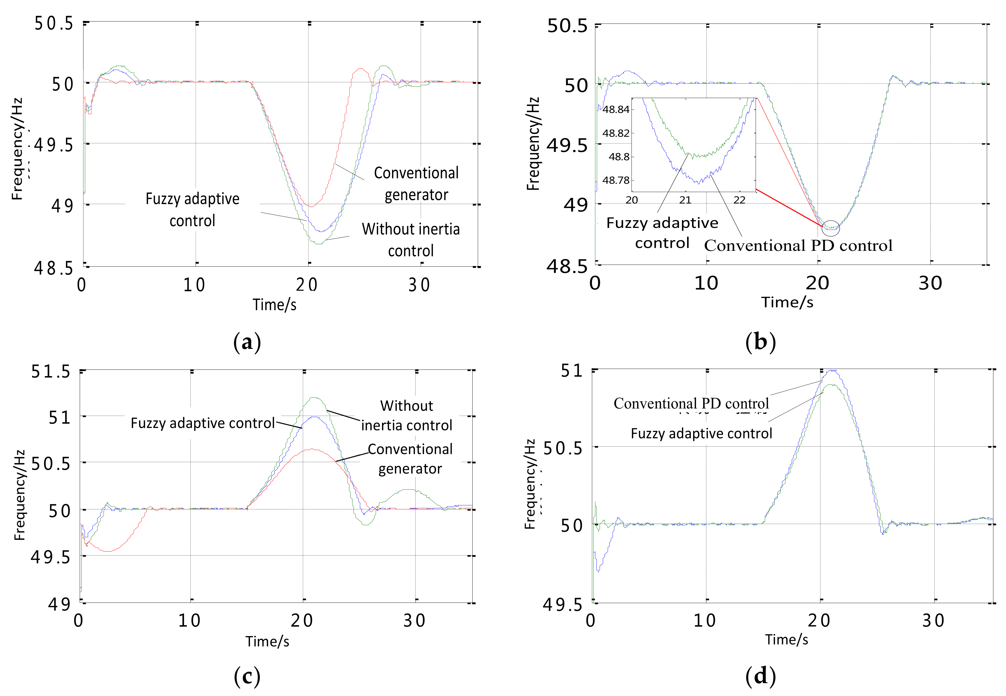
The system running state is normal during the period from 0 to 15 s. There is a small fluctuation in the start moment, and the frequency will be stable at the normal values in about 5 s. The active load suddenly pluses 1.5 MW in 15 s, the system frequency curves the without inertia control, fuzzy adaptive PD inertia control, and all of the conventional units supply are compared in Figure 5.
In Figure 5a,b, the lowest system frequency is 49 Hz and returns to normal after 13 s, when the failure traditional synchronous generator connects to the electrical grid. The lowest frequency is 48.65 Hz using the same capacity of DFIG, which drops 0.35 Hz and the drop rate has a share of 0.71% as compared with the one of the traditional synchronous motor, and returns to the normal after 17 s once the failure happens. Thus, the without inertia control will strongly affect the stability of the system frequency. When compared with the traditional synchronous generator, the difference is only 0.2 Hz, and the recovery time is approximately 13 s after the failure. The stability of the system frequency has a significant improvement by using the fuzzy adaptive PD inertia control method. When the active load of the system suddenly reduces to 1.5 MW, the comparison of the results on the same working status can be seen from Figure 5c,d.
When the system load has a fluctuation, the frequency response has been compared by using the conventional units and the wind power generator without inertia control. The maximum frequencies without inertia control and with the traditional units are 51.25 and 50.65 Hz, respectively. The maximum frequency is 51 Hz by using the fuzzy adaptive PD control strategy, which is closer to the frequency response of the conventional generator when the same failure occurs, as shown in Figure 5c,d.
As mentioned above, the DFIG has the inertia response by using the fuzzy adaptive PD control strategy that is proposed in this paper, it is closer the inertia result of the conventional generator units with the same capacity.

5.2. Data Analysis at Different HESS Capacity Configuration

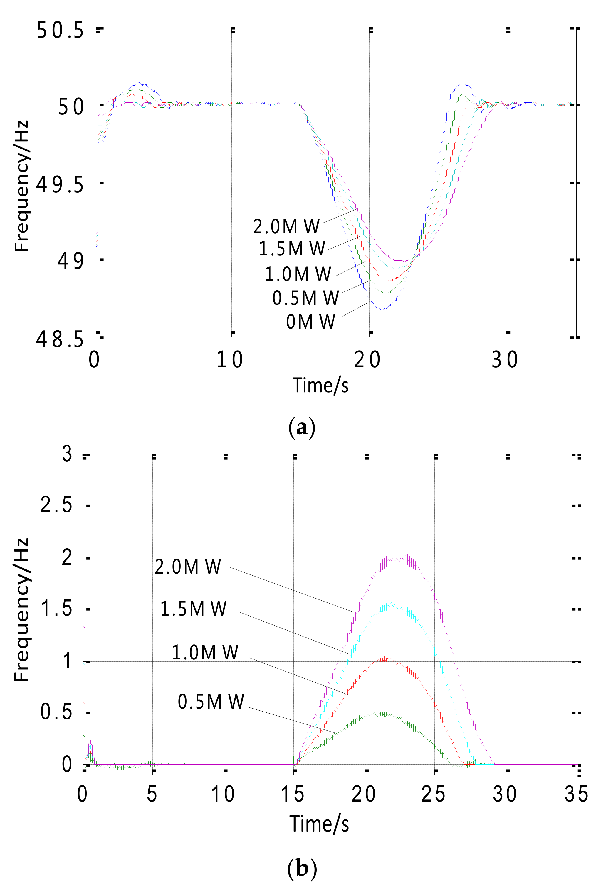
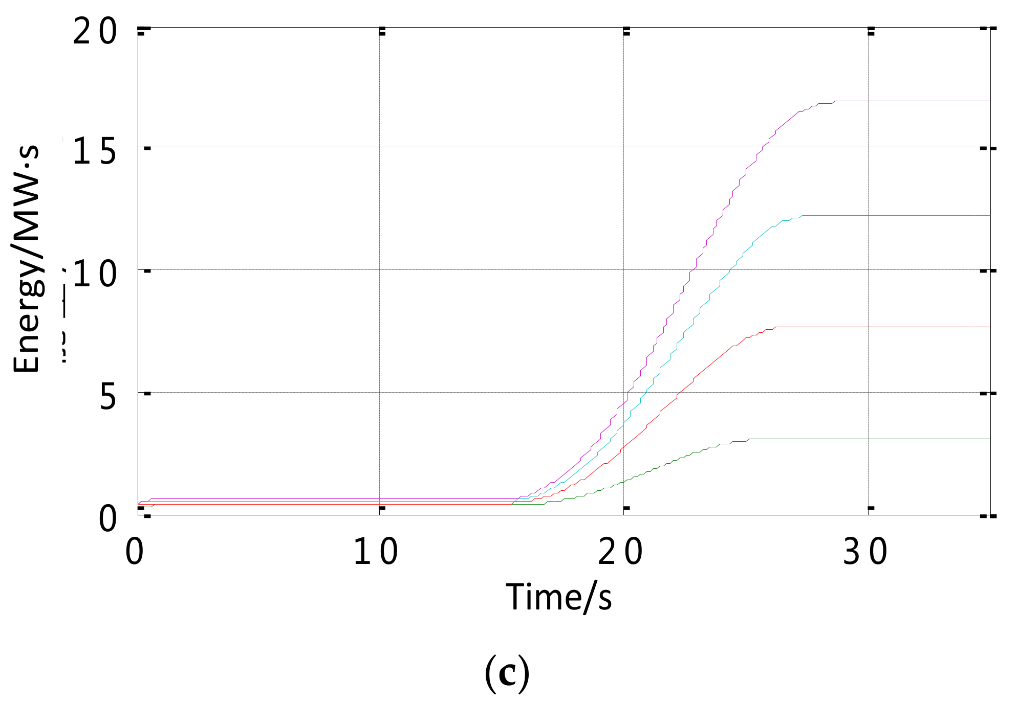
The virtual inertia response of different HESS capacity at the sudden increase of the load is discussed in this part.
The HESS can achieve on-line monitoring of the generators’ conditions, changing rate, and variation of system frequency by using the proposed virtual inertial adaptive control strategy. The input and output powers of the HESS are directly related the virtual inertia, which has a great effect on the changing frequency of the HESS system. The virtual inertia effects are different under different HESS capacity configuration conditions. Once the capacity increases, the frequency modulation is easier to track, as can be seen in Figure 6a. The lowest frequency falls to 49 Hz, when the HESS capacity is 2 MW. By comparing with the one without a storage system, the frequency increased by 0.35 Hz. With the capacity of the HESS increasing, there is less influence to the stability of the system frequency by comparing the effects of different energy storage configurations in Figure 6. Specially, the virtual inertia control effect is similar to the control effect using the conventional generator when the HESS capacity configuration is 0.5 MW. 
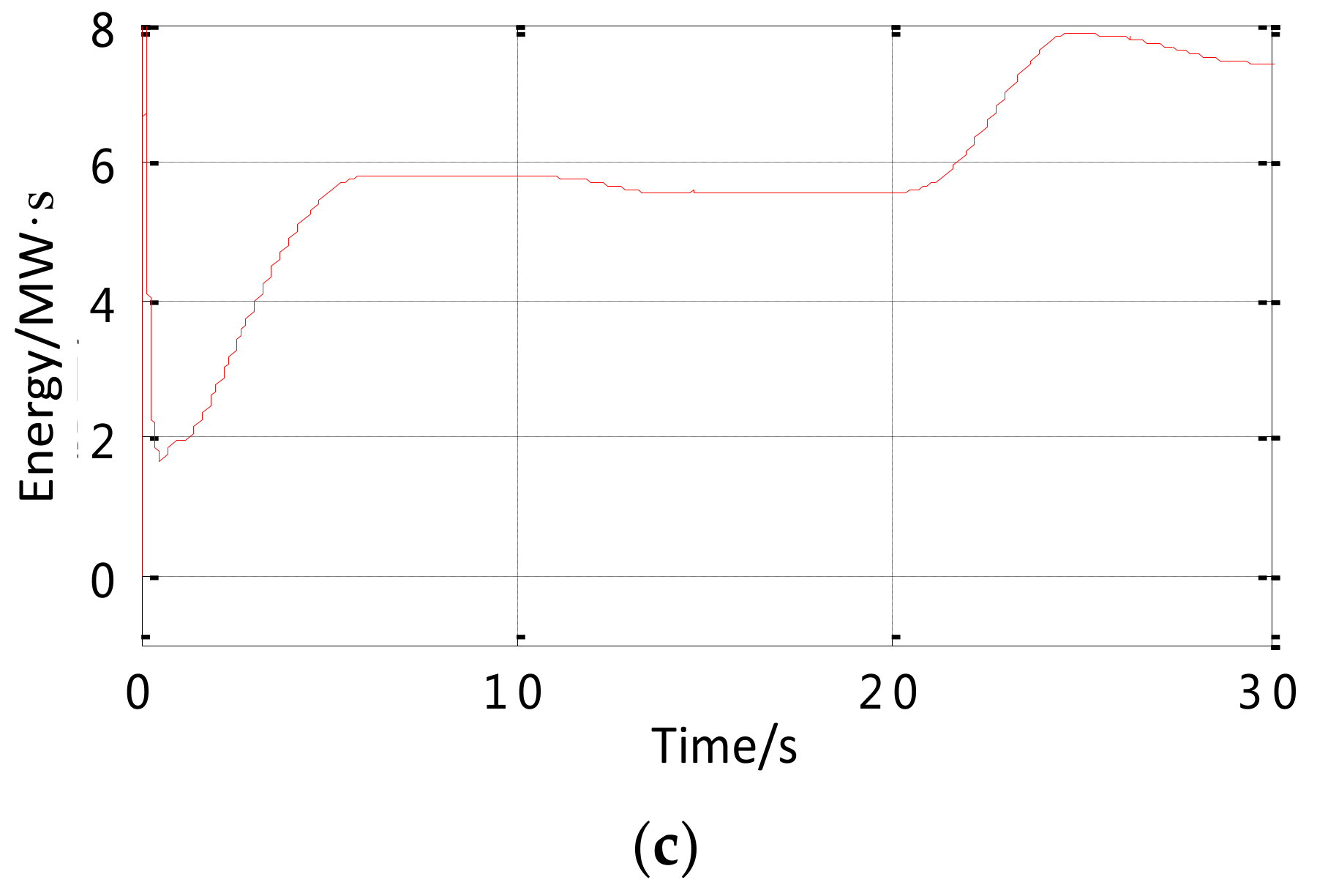
Figure 6b,c show that the HESS’s output is changing with the change of the system frequency. When the system runs for 15 s, the sudden increase of the load leads to the deterioration of the system frequency, and the HESS immediately responds to increase the power and discharge to the electrical system. When the system runs to 27 s, then the system frequency entered the recovery phase at different HESS capacity. The HESS reduces the system output and decreases the virtual inertia to ensure a quick recovery of the system frequency.

5.3. Data Analysis for the Wind Speed Fluctuations

The wind speed in the actual wind farm continuously changes, and the output power of the wind farm is fluctuant with the changing wind speed. In this case, due to variations of actual wind speeds, the system frequency produces big fluctuations and brings a great disturbance for the security and stability of the power system. The proposed system can not only play a role to restrain the wind power fluctuation, but also to reduce the change rate of frequency and improve the limit of frequency fluctuation by using the virtual inertial control strategy.
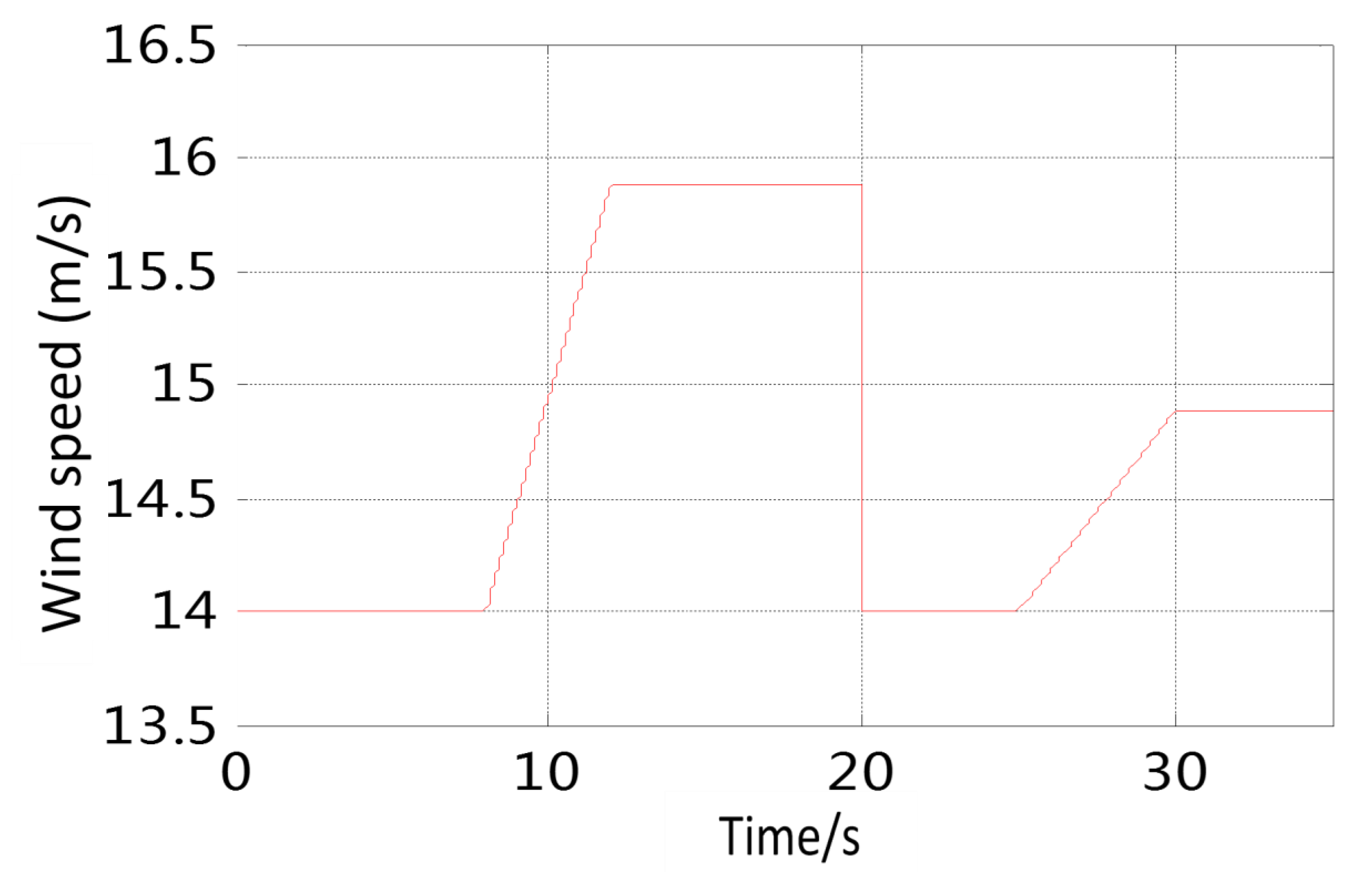
The wind speed of the wind farm in the set simulation condition are parameterized, as shown in Figure 7a. The wind speed is constant at the value of 14 m/s from 0 to 8 s. The wind speed suddenly dropped to 14 m/s after a stable period and the wind speed was stable at 14.8 m/s after a small fluctuation.
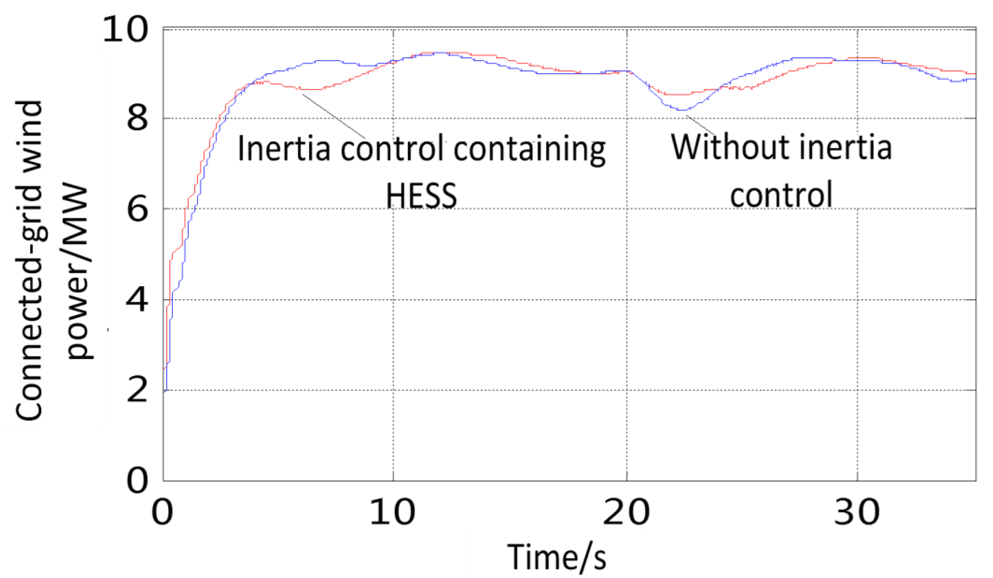
In Figure 7b, the change curves of the developed system in different condition are illustrated. The grid-connected power of the wind power system is rising from 0 MW at initial stage, which follows the change of the wind speed. There is a big overshoot in the without virtual inertial control method. By comparing the virtual inertial control strategy, there is a reduction at the overshoot, and the wind power is closer to the rated value of 9 MW. The wind speed suddenly decreases in the middle and later stages of the wind speed, while the grid-connected power of the wind power is also descending. However, the declining speed of the wind power is slow using the virtual inertial control contains the HESS, and the final limit is smaller. With the wind speed fluctuation of the wind farm, the grid-connected power of the wind power is stable using the virtual inertial control containing the HESS, and there is only a small difference to compare with the rated value of the grid-connected wind power.
In Figure 8a, the changes of wind power from the initial stage to the rated stage have a great impact on the frequency of the system. The initial stage frequency is significantly reduced after a short period of oscillation. After that, with the increasing of wind power, the frequency has an overshoot with different degrees. The grid-connected wind power stabilizes at a constant value after a sudden decrease in the middle and the later stages of the change in wind speed, and the frequency also drops and gradually stabilizes to the normal values. The frequency fluctuation range without using the inertial control is significant with the lower limit and upper limit values being 49.2 and 50.8 Hz, respectively. When the system frequency is lower than the rated value, the fuel cell device of the HESS starts to release the power, on the contrary, when the system frequency is higher than the rated value, the fuel cell device of the HESS starts to absorb the power. When the HESS capacity is 1.3 MW, the system frequency can stable in the range of plus or minus 0.2 Hz at the wind speed continuous fluctuation, which meets the requirements of the system frequency variation range of the electrical grid operation under normal conditions in Figure 8b,c.

6. Conclusions

The virtual inertia control of a doubly fed induction generator based wind farm with hydrogen energy storage system is proposed in this paper. The HESS capacity configuration is developed to produce a similar inertial response to the traditional synchronous generators. The inertia of the wind farm is improved by using the HESS in terms of the frequency support of the wind farm. The following conclusions can be obtained:
(1)
The HESS can effectively change the virtual inertia of the wind turbine and provide wind farm with support for the system frequency stability.
(2)
When the system load suddenly changes, the proposed adaptive control strategy can efficiently increase the virtual inertia, responding to the change of the system frequency, and supports the stability of the system frequency.
(3)
The virtual inertia of the system increases with the HESS capacity, which can improve the frequency modulation. The storage system with the 5% rated power is effective in producing the inertia that is required by a conventional synchronous generator with the same rating.
(4)
The proposed adaptive control strategy can assure the good inertia response and restrain the frequency change even if the frequency change reaches the lower limit of the system.
The developed technology can be applied to medium and large wind turbine systems. When compared to traditional systems, the proposed system is more complicated and costly at the stage. However, the economic gain could be improved in the long run by improving frequency stability and energy efficiency as well as commercializing the developed technology.

Acknowledgments

This study is funded by National Key Research and Development Plan of China (2017YFB0903500), National Natural Science Foundation of China (51577163) and Key Research Project of State Grid Corporation of China (5230HQ16016U).

Author Contributions

Tiejiang Yuan and Jinjun Wang conceived the research; Yuhang Guan performed the simulation model and controller design; Zheng Liu performed model validation and wrote the paper; Xinfu Song and Yong Che performed data collection and analysis; Wenping Cao critically revised the paper and provided constructive criticism.

Conflicts of Interest

The authors declare no conflicts of interest

References

  1. Vidyanandan, K.V.; Senroy, N. Primary frequency regulation by deloaded wind turbines using variable droop. IEEE Trans. Power Syst. 2013, 28, 837–846. [Google Scholar] [CrossRef]
  2. Ma, J.; Qiu, Y.; Li, Y.N.; Zhang, W.B.; Song, Z.X.; Thorp, J.S. Research on the impact of DFIG virtual inertia control on power system small-signal stability considering the phase-locked loop. IEEE Trans. Power Syst. 2017, 32, 2094–2105. [Google Scholar] [CrossRef]
  3. Moghaddam, A.M.F.; El-Saadany, E.F. Implementing virtual inertia in DFIG-based wind power generation. IEEE Trans. Power Syst. 2013, 28, 1373–1384. [Google Scholar]
  4. Ramtharan, G.; Ekanayake, J.B.; Jenkins, N. Frequency support from doubly fed induction generator wind turbines. IET Renew. Power Gener. 2007, 1, 3–9. [Google Scholar] [CrossRef]
  5. Gowaid, I.A.; Elzawawi, A.; Elgammal, M. Improved inertia and frequency support from grid-connected DFIG wind farms. In Proceedings of the 2011 IEEE/PES Power Systems Conference and Exposition 2011, Phoenix, AZ, USA, 20–23 March 2011; pp. 1109–1117. [Google Scholar]
  6. Teninge, A.; Jecu, C.; Roye, D.; Bacha, S.; Duval, J.; Belhomme, R. Contribution to frequency control through wind turbine inertial energy storage. IET Renew. Power Gener. 2009, 3, 358–370. [Google Scholar] [CrossRef]
  7. Miao, L.; Wen, J.; Xie, H.; Yue, C.; Lee, W.J. Coordinated control strategy of wind turbine generator and energy storage equipment for frequency support. IEEE Trans. Ind. Appl. 2015, 51, 2732–2742. [Google Scholar] [CrossRef]
  8. Tapia, A.; Tapia, G.; Ostolaza, J.X.; Saenz, J.R. Modeling and control of a wind turbine driven doubly fed induction generator. IEEE Trans. Energy Convers. 2003, 18, 194–204. [Google Scholar] [CrossRef]
  9. Luo, X.; Wang, J.; Dooner, M.; Clarke, J. Overview of current development in electrical energy storage technologies and the application potential in power system operation. Appl. Energy 2015, 137, 511–536. [Google Scholar] [CrossRef]
  10. Garcia-Gonzalez, J.; Muela, R.M.R.; Santos, L.M.; Gonzalez, A.M. Stochastic joint optimization of wind generation and pumped-storage units in an electricity market. IEEE Trans. Power Syst. 2005, 23, 460–468. [Google Scholar] [CrossRef]
  11. Denholm, P.; Sioshansi, R. The value of compressed air energy storage with wind in transmission-constrained electric power systems. Energy Policy 2009, 37, 3149–3158. [Google Scholar] [CrossRef]
  12. Bolund, B.; Bernhoff, H.; Leijon, M. Flywheel energy and power storage systems. Renew. Sustain. Energy Rev. 2007, 11, 235–258. [Google Scholar] [CrossRef]
  13. Dunn, B.; Kamath, H.; Tarascon, J.M. Electrical energy storage for the grid: A battery of choices. Science 2011, 334, 928–935. [Google Scholar] [CrossRef] [PubMed]
  14. Qian, H.; Zhang, J.; Lai, J.S.; Yu, W. A high-efficiency grid-tie battery energy storage system. IEEE Trans. Power Electron. 2011, 26, 886–896. [Google Scholar] [CrossRef]
  15. Kear, G.; Shah, A.A.; Walsh, F.C. Development of the all-vanadium redox flow battery for energy storage: A review of technological, financial and policy aspects. Int. J. Energy Res. 2012, 36, 1105–1120. [Google Scholar] [CrossRef]
  16. Pal, B.C.; Coonick, A.H.; Macdonald, D.C. Robust damping controller design in power systems with superconducting magnetic energy storage devices. IEEE Trans. Power Syst. 2000, 15, 320–325. [Google Scholar] [CrossRef] [Green Version]
  17. Li, W.; Joós, G.; Bélanger, J. Real-time simulation of a wind turbine generator coupled with a battery supercapacitor energy storage system. IEEE Trans. Ind. Electron. 2010, 57, 1137–1145. [Google Scholar] [CrossRef]
  18. Sherif, S.A.; Barbir, F.; Veziroglu, T.N. Wind energy and the hydrogen economy—Review of the technology. Sol. Energy 2005, 78, 647–660. [Google Scholar] [CrossRef]
  19. Malik, M.; Dincer, I.; Rosen, M.A. Development and analysis of a new renewable energy-based multi-generation system. Energy 2015, 79, 90–99. [Google Scholar] [CrossRef]
  20. Kroniger, D.; Madlener, R. Hydrogen storage for wind parks: A real options evaluation for an optimal investment in more flexibility. Appl. Energy 2014, 136, 931–946. [Google Scholar] [CrossRef]
  21. González, A.; Mckeogh, E.; Gallachóir, B.Ó. The role of hydrogen in high wind energy penetration electricity systems: The Irish case. Renew. Energy 2004, 29, 471–489. [Google Scholar] [CrossRef]
  22. Bortolini, M.; Gamberi, M.; Graziani, A. Technical and economic design of photovoltaic and battery energy storage system. Energy Convers. Manag. 2014, 86, 81–92. [Google Scholar] [CrossRef]
  23. Sardi, J.; Mithulananthan, N. Community energy storage, a critical element in smart grid: A review of technology, prospect, challenges and opportunity. In Proceedings of the 2014 4th International Conference on Engineering Technology and Technopreneuship (ICE2T), Kuala Lumpur, Malaysia, 27–29 August 2014; pp. 125–130. [Google Scholar]
  24. Shen, Y.W.; Ke, D.P.; Sun, Y.Z.; Kirschen, D.S.; Qiao, W.; Deng, X.T. Advanced auxiliary control of an energy storage device for transient voltage support of a doubly fed induction generator. IEEE Trans. Sustain. Energy 2016, 7, 63–76. [Google Scholar] [CrossRef]
  25. Bhogilla, S.S.; Ito, H.; Kato, A.; Nakano, A. Research and development of a laboratory scale totalized hydrogen energy utilization system. Int. J. Hydrogen Energy 2016, 41, 1224–1236. [Google Scholar] [CrossRef]
  26. Fan, X.C.; Wang, W.Q.; Shi, R.J.; Cheng, Z.J. Hybrid pluripotent coupling system with wind and photovoltaic-hydrogen energy storage and the coal chemical industry in Hami, Xinjiang. Renew. Sustain. Energy Rev. 2017, 72, 950–960. [Google Scholar] [CrossRef]
  27. Hu, J.; Sun, L.; Yuan, X.; Wang, S.; Chi, Y. Modeling of type 3 wind turbines with df/dt inertia control for system frequency response study. IEEE Trans. Power Syst. 2017, 32, 2799–2809. [Google Scholar] [CrossRef]
  28. Gautam, D.; Vittal, V.; Harbour, T. Impact of increased penetration of DFIG-based wind turbine generators on transient and small signal stability of power systems. IEEE Trans. Power Syst. 2009, 24, 1426–1434. [Google Scholar] [CrossRef]
  29. Wang, Y.; Chen, K.S.; Mishler, J.; Cho, S.C.; Adroher, X.C. A review of polymer electrolyte membrane fuel cells: Technology, applications, and needs on fundamental research. Appl. Energy 2011, 88, 981–1007. [Google Scholar] [CrossRef]
  30. Technical Committee of Power Grid Operation and Control Standardization. DL/T1040-2007. In Power System Operation and Control of the Power Industry Standardization Technical Committee; China Electric Power Press: Beijing, China, 2007. [Google Scholar]
  31. Erinmez, I.A.; Bickers, D.O.; Wood, G.F.; Hung, W.W. NGC experience with frequency control in England and Wales-provision of frequency response by generators. In Proceedings of the IEEE Power Engineering Society 1999 Winter Meeting, New York, NY, USA, 31 January–4 February 1999; pp. 590–596. [Google Scholar]
  32. Wang, C.; Nehrir, M.H. Power management of a stand-alone wind/photovoltaic/fuel cell energy system. IEEE Trans. Energy Convers. 2008, 23, 957–967. [Google Scholar] [CrossRef]
  33. Karnavas, Y.L.; Papadopoulos, D.P. Excitation control of a power-generating system based on fuzzy logic and neural networks. Int. Trans. Electr. Energy Syst. 2000, 10, 233–241. [Google Scholar] [CrossRef]
  34. Vazquez, S.; Lukic, S.M.; Galvan, E.; Franquelo, L.G.; Carrasco, J.M. Energy storage systems for transport and grid applications. IEEE Trans. Ind. Electron. 2010, 57, 3881–3895. [Google Scholar] [CrossRef]
  35. Wang, H.; Chen, Z.; Jiang, Q. Optimal control method for wind farm to support temporary primary frequency control with minimised wind energy cost. IET Renew. Power Gener. 2014, 9, 350–359. [Google Scholar] [CrossRef]
Figure 1. Energy transfers relation of the doubly fed induction generator (DIFG) coupling hydrogen energy storage system (HESS).
Energies 11 00904 g001
Figure 2. Virtual inertial control model containing the hydrogen storage system.
Energies 11 00904 g002
Figure 3. Fuzzy adaptive PD control structural drawing.
Energies 11 00904 g003
Figure 4. Fuzzy adaptive PD corrected parameters drawing. (a) Drawing of   Δ k p ; (b) Drawing of Δ k d . and Δ k p .
Energies 11 00904 g004
Figure 5. The frequency’s response curve at the load sudden increase and decrease. (a) The frequency’s response curve of fuzzy adaptive control, conventional generator and without inertia control with load increase; (b) The frequency’s response curve of fuzzy adaptive control and conventional PD control with load increase; (c) The frequency’s response curve of fuzzy adaptive control, conventional generator and without inertia control with load decrease; and (d) The frequency’s response curve of fuzzy adaptive control and conventional PD control with load decrease with load decrease.
Energies 11 00904 g005
Figure 6. The inertial response and system output of HESS capacity changes. (a) The frequency’s response curve at the load sudden increase; (b) The frequency’s response curve at the load sudden decrease; and (c) Energy’s response curve.
Energies 11 00904 g006aEnergies 11 00904 g006b
Figure 7. Data analysis for the wind speed fluctuation. (a) The wind speed fluctuation of the wind farm; (b) The connected-grid power of the doubly fed induction generator wind power system with hydrogen energy storage.
Energies 11 00904 g007aEnergies 11 00904 g007b
Figure 8. The change of the system frequency and the HESS output at the power fluctuation. (a) The system frequency responses with and without inertia control; (b) Output power response of HESS; and (c) Output energy response of HESS.
Energies 11 00904 g008aEnergies 11 00904 g008b
Table 1. Fuzzy control of Δ k d
ecNBNMNSZOPSPMPB
Δkpkb
e
NBPBPBPBPMPSZONS
NMPBPBPMPSZONSZO
NSPBPMPSZONSZOPS
ZOPMPSZOZOZOPSPM
PSPSZOZSZOPSPMPB
PMZONSZOPSPMPBPB
PBNSZOPSPMPBPBPB
Table 2. Parameters of the doubly fed induction generator (DFIG).
Unit capacity (MVA)1.5Number of pole-pairs3
Stator voltage (V)575Rotor voltage (V)1975
Stator resistance (p.u.)0.023Rotor resistance (p.u.)0.016
Stator inductance (p.u.)0.18Rotor inductance (p.u.)0.16
Mutual inductance (p.u.)2.9Frequency (Hz)50
Table 3. Parameters of the synchronous generator.
Capacity (MVA)40Number of pole-pairs1
Stator voltage (V)575Frequency (Hz)50
Stator resistance (p.u.)0.0045Inertia time constant (s)2
d-axis synchronous reactance (p.u.)1.65q-axis synchronous reactance (p.u.)1.59
d-axis transient reactance (p.u.)0.25q-axis transient reactance (p.u.)0.46
d-axis subtransient reactance (p.u.)0.2q-axis subtransient reactance (p.u.)0.2

