Coalbed Methane Extraction Using the Self-Oscillating Water Jet Slotting Method

1
State Key Laboratory of Coal Mine Disaster Dynamics and Control, Chongqing University, Chongqing 400044, China
2
College of Resources and Environmental Science, Chongqing University, Chongqing 400030, China
*
Author to whom correspondence should be addressed.
Energies 2018, 11(4), 897; https://doi.org/10.3390/en11040897
Submission received: 6 March 2018
/
Revised: 3 April 2018
/
Accepted: 9 April 2018
/
Published: 11 April 2018
Abstract
:Self-oscillating Water Jet (SOWJ) slotting in Coalbed Methane (CBM) is proposed to overcome low gas permeability, high gas desorption, and difficult mining in deep coal beds. SOWJ slotting excitation expands the fracture network, increases coal permeability, and strengthens gas desorption. The coupled effect of these three processes increases CBM extraction. Analysis of the characteristics of SOWJ, the effect of coal slotting, and changes in coal permeability shows that (1) SOWJ impacts on coal-rock mass, forming the erosion–peeling zone, fragmentation zone, and distal conical crack zone in the rock. The jet impact and cavitation sonic vibrating effect generate coal vibration; (2) The slots and fractures formed by the jets release the coal’s elastic energy, depressurising the coal and changing the stress field. The stress redistribution further expands the fractures and the subsequent perforative fracture network; (3) Slot formation increases the coal’s exposed area, changing the gas flow pattern. The decrease of effective stress increases coal permeability; the vibration characteristics of the jets and the cavitation sonic vibrating effect enhance gas desorption, which increases gas emission; (4) Extraction field tests showed that single-hole extraction of CBM from conventional boreholes was 1606 m3 and the average standard scalar volume was 0.01 m3/min, compared to 7081 m3 and 0.042 m3/min for SOWJ slotting boreholes, 4.41 and 4.2 times, respectively, of the conventional boreholes. Thus, SOWJ slotting can significantly improve CBM mining.
1. Introduction
Coalbed methane (CBM) is an unconventional gas stored in coal matrix as free and adsorptive state types [1]. While it is a most hazardous material, posing a high risk to coal mine safety, it is also a valuable clean energy source [2]. The mining of CBM to replace traditional energy sources is carried out in many countries, including the United States, Australia, Canada, and China [3]. In China, CBM resources are abundant and the requirement for efficient exploitation of CBM is included in energy development strategies and coal production safety standards [4]. Research on the amount of shallow-layer (within 3000-m depth) CBM resources in China found that CBM volumes within 1000–1500 m and 1500–3000 m are about 21 trillion m3 and 30 trillion m3, respectively, accounting for 38.2% and 54.5% of the total CBM resources, respectively, while the resources within a 1000-m depth make up only 7.3% of the total [5]; this indicates that China’s CBM resources are mainly found in deep coal seams. As coal seams are being mined at increasingly deeper layers, mining conditions become more complex. These conditions include increased in-situ stress, decreased coal gas permeability, and high levels of gas desorption. Traditional methods of gas extraction cannot effectively increase gas permeability and desorption, resulting in difficulties in CBM exploitation. When coal seam outbursts occur, the high-pressure gas, which is difficult to mine, can cause huge damage, serious injuries, and loss of life. Therefore, it is important to improve the permeability of the coal to enable the efficient extraction of CBM. Many scholars have developed methods to increase coal permeability, including protective layer mining, hydraulic slotting, hydraulic fracturing, and presplitting blasting. A protective mining layer [6,7] increases the permeability of the coal seam, mainly by depressurising the coal; the hydraulic slotting, hydraulic fracturing, and presplit blasting methods increase the permeability mainly through forming fracture networks [8,9,10]. However, Zhao et al.’s research indicated that enhancing gas desorption is also an important factor in increasing CBM extraction [11,12]. While recent studies demonstrated that each of these three factors contributes to CBM extraction, no method has been developed to effectively utilize all three factors simultaneously to increase the CBM extraction. Additionally, hydraulic fracturing and presplit blasting are pressurization processes, while SOWJ is a pressure unloading process. In a coal mine with high in-situ stress, hydraulic fracturing and presplit blasting methods may increase the stress of the coal body and cause disasters.
The Self-oscillating Water Jet (SOWJ) slotting method, proposed by the author, can be applied in high-efficiency CBM mining by controlling and expanding the fracture network, improving the permeability of the coal, and strengthening gas desorption. As SOWJ slotting is highly energy-absorbing, slot cavities and impact fractures can be formed rapidly. Slots and fracture space thus created can significantly expand the gas emission free surface, releasing the elastic energy of the coal and depressurising the coal, thus modifying the coal stress field. The redistribution of stress causes the initial cracks (at the tips of the slots) to develop and expand, and the gradual accumulation of damage around the slots generates new fractures; thus, perforated fracture networks are created in the coal seam. The depressurisation and the formation of the fracture networks has a widespread effect of improving the permeability of the coal seam. Meantime, the coal vibration, caused by the jet impact and the cavitation sonic vibrating effect, further stimulates the evolution of fractures and promotes the desorption of coal gas to free gas. With the gradual removal of gas from the coal, the pressure of the coal gas drops, which once again promotes the depressurisation of the coal and further expansion of the fracture field. The combined effect of all these phases creates a positive circulation system of CBM mining.
In this study, the author presents a comprehensive review of SOWJ slotting technology and its theory. By means of theoretical analysis, laboratory experiments, and numerical simulation, the rock-breaking characteristics of the SOWJ slot effects and the resulting change of permeability are investigated, revealing the mechanism of the SOWJ slotting technology which improves CBM production efficiency.
2. Characteristics of the Self-Oscillating Water Jet
When applying water jet slotting, a high jet pressure is required to achieve a good slotting effect. However, the high-pressure can reduce the safety, reliability, and service life of the equipment. Hence, SOWJ slotting was proposed, whereby enhanced erosion and slotting effects were achieved by utilizing the water hammer effect, high-speed lateral flow, and high-frequency impact pressure of water jets in a low-pressure system [13,14]. In this method, large-scale step-type mass-breaking was induced by jets with pressure levels within the rock compressive durability.
2.1. Mechanism of SOWJ Generation and Its Characteristics
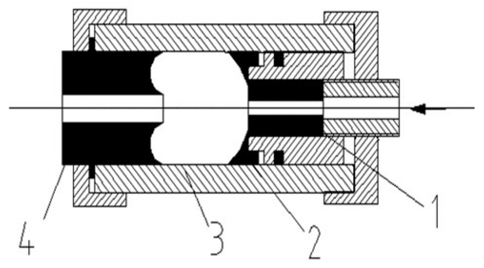
The self-oscillatory pulse gas–liquid jetting nozzle is illustrated in Figure 1. When the jet enters the oscillation chamber from the upstream nozzle, a shear layer is formed, and the disturbance peak is enlarged, thereby colliding with the impinging wall. As the sectional area of the jet at this point is greater than that at the downstream exit, pressure transients are caused by the speed change. The transients then reflect upstream along the jet axis at sound velocity α and generate more pressure transients at the upstream nozzle; this generates a strong disturbance at the upstream nozzle, which is transported downstream with the shear layer and amplified, colliding again going downstream, resulting in pressure transients. Inside the self-excited oscillatory nozzle, the fluid undergoes a four-stage cycle: disturbance–amplification–collision–feedback. A positive feedback closed loop is thus created, forming the self-excited oscillations.
In this process, the oscillation frequency of the jets can be calculated according to the spacing of the adjacent vortex rings:
where f is the oscillation frequency of the SOWJ, in Hz; c is the pressure wave propagation velocity, in m/s; n is the number of modes, n = 1, 2, 3, …; and L is the length of the oscillation chamber, in m.
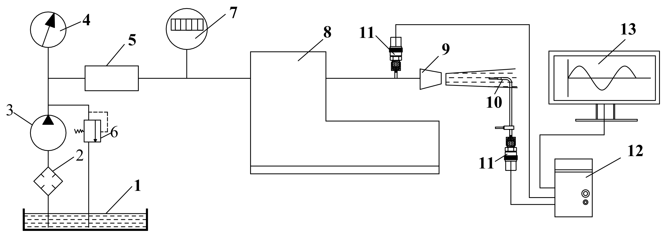
To verify the pressure pulsation and high energy-gathering characteristics, pulsed water jets were tested in the laboratory using a pressure pulsation testing device (Figure 2).
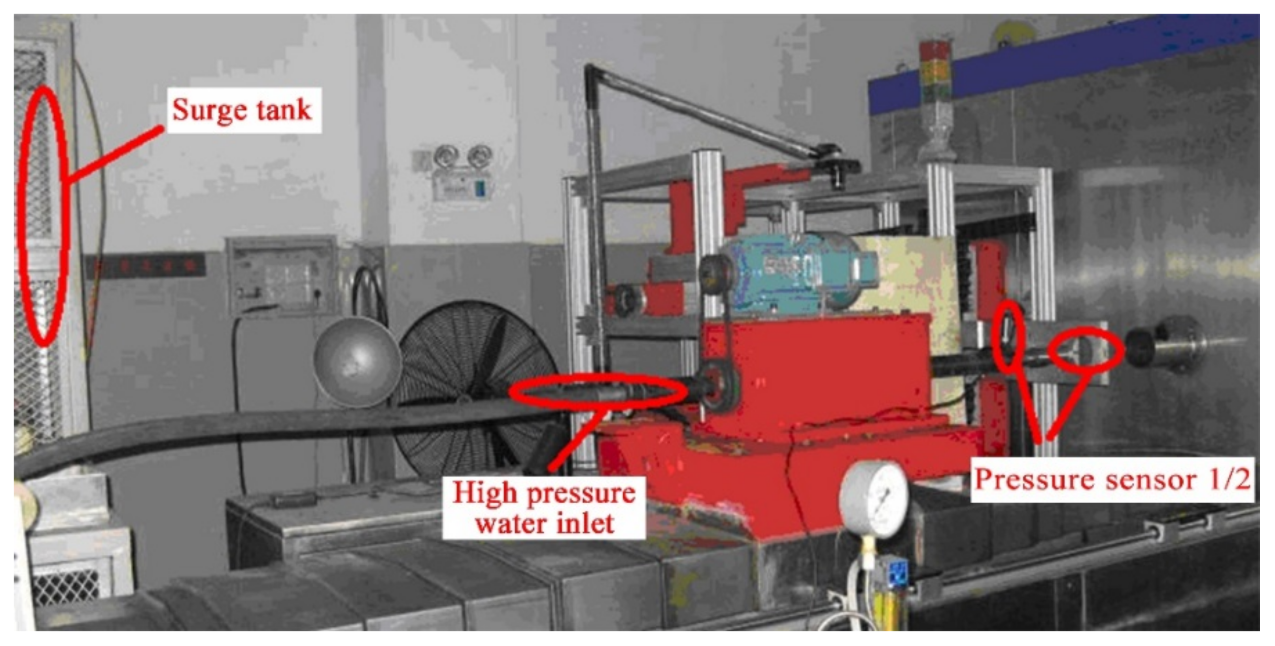
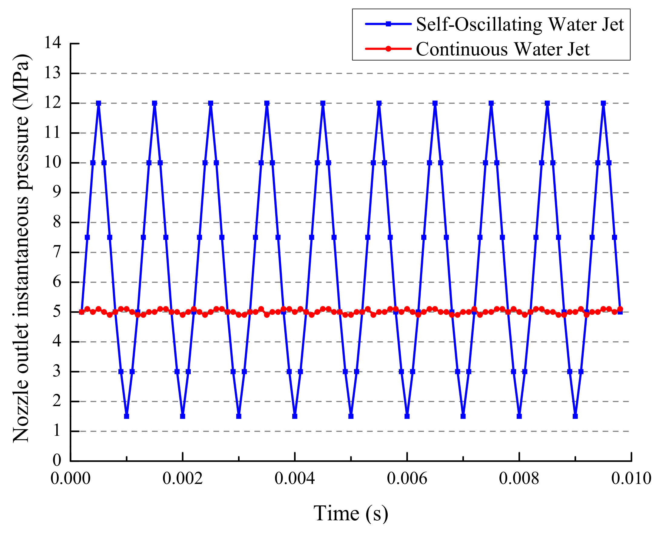
The pressure measurement system was set up to carry out ordinary continuous jet nozzle and SOWJ nozzle pressure tests (Figure 3). During the experiment, the pump pressure was set to 5 MPa; to prevent pressure fluctuations caused by the plunger pump, the surge tank was attached to the pipeline for pressure adjustments. Pressure sensor #1 was installed at the inlet of the nozzle to ensure a constant nozzle inlet pressure. Pressure sensor #2 was installed in the nozzle outlet flow field to compare and test the variation of the jet pressure at the nozzle exit of the two different types of structures. The pressure curves recorded in the test (Figure 4) show that the jet generated through the standard conical convergent nozzle was solid and continuous, and the pressure fluctuation was minimal and almost constant. Conversely, the jet generated through the self-excited oscillatory nozzle shows clear fluctuations, which can produce oscillating jets with a high peak pressure and a stable frequency. The peak pressure was, by calculation, about 2.5 times that of the solid jet generated by the conventional nozzle, indicating that the oscillating jets are more effective in impacting and eroding the coal and rock mass.
2.2. Rock-Breaking Characteristics of the SOWJ Impact
The water hammer effect of the SOWJ causes the pressure created by the high-pressure water jet to spread and propagate inside the coal-rock mass in the form of a stress wave and on the surface of the coal-rock mass (Figure 5) in the form of a Rayleigh surface wave. Pianthong et al. [15] showed that when the tensile and shear stresses, brought by the impact of the stress wave on the particles of the same spherical surface, exceeded the tolerance of the coal, a penetrative net surface crack appeared, which ultimately led to fracturing and collapse of the rock mass.
Because the coal specimen was too weak, after the crushing impact of the high pressure self-oscillating jet, it was impossible to form an intuitive fracture morphology. Furthermore, the coal specimen has large discreteness, which will affect the result of comparison between multiple specimens. Therefore, sandstone of a higher strength and better homogeneity was selected as test specimens. The properties are shown in Table 1. The sandstone rock core dimensions were: φ50 × 50 mm.
To observe the macroscopic effect of coal-rock mass crushing by SOWJ, sandstone specimens were subjected to water jets at different velocities in the laboratory. The crushed coal-rock specimens were photographed from the front and side with a camera, and MATLAB software (Matlab R2012b, MathWorks, Natick, MA, USA) was used for binary digital processing of the photos. Figure 6 shows the macroscopic crushing of the sandstone samples after the impact of water jets at different velocities.
The impact of the SOWJ formed three damage zones in the specimens: the erosion–peeling zone, fragmentation zone, and distal conical crack zone (Figure 7). Under the water hammer effect, the coal-rock mass was crushed and smashed by the high-pressure water jet, peeling the surface of the coal-rock mass and forming a groove in the mass. Three types of cracks exist in a cursed area, which are radial cracks, circumferential cracks, and conic cracks. The radial and circumferential cracks are mostly distributed in the vicinity of the groove space, forming a high-density crack zone; these cracks are likely the result of the joint interaction of the shear and tensile stress components. The distal conical crack zone, generated in the vicinity of the groove space, expands outward extensively in the form of a single crack.
2.3. Cavitation Sonic Vibration Effect of the SOWJ
As the holes produced in the slotting process are in the submerged state, a variety of vortex structures are formed by the disturbance. The centre of the vortex is the low-pressure area, where when the local liquid pressure decreases to the saturated vapour pressure, vapour or gas bubbles appear inside the liquid and on the surface of the liquid–solid boundaries. The formation and collapse of the bubbles induces the cavitation sonic vibration effect. In the process of bubble collapse, a local high temperature of about 5000 K and a pressure of 500 atmospheres is generated, accompanied by a strong shock wave and high-speed micro-jets [16]. Thus, strong vibrations are produced by the cavitation sonic effect. During the formation, development, and collapse of the bubbles, the sonic boom effect is generated. The sound wave radiation during the process is of the pulsating-source (monopole) type, which is a very effective source. The bubbles have a high volumetric pulsation rate when the radius of the bubbles is close to its minimum value and the bubbles collapse. Despite the small volume of the bubbles in the collapse phase, the radiation pressure generated by the sonic boom is substantial. Therefore, the cavitation sonic vibrating effect is strongest during the cavitation bubble collapse stage. When the SOWJ impacts on the surface of the coal-rock mass, a powerful energy transfer process occurs due to the cavitation sonic vibrating effect, which causes strong mechanical vibration of the coal-rock mass. Meanwhile, the temperature rises and mechanical vibration and thermal effects are induced.
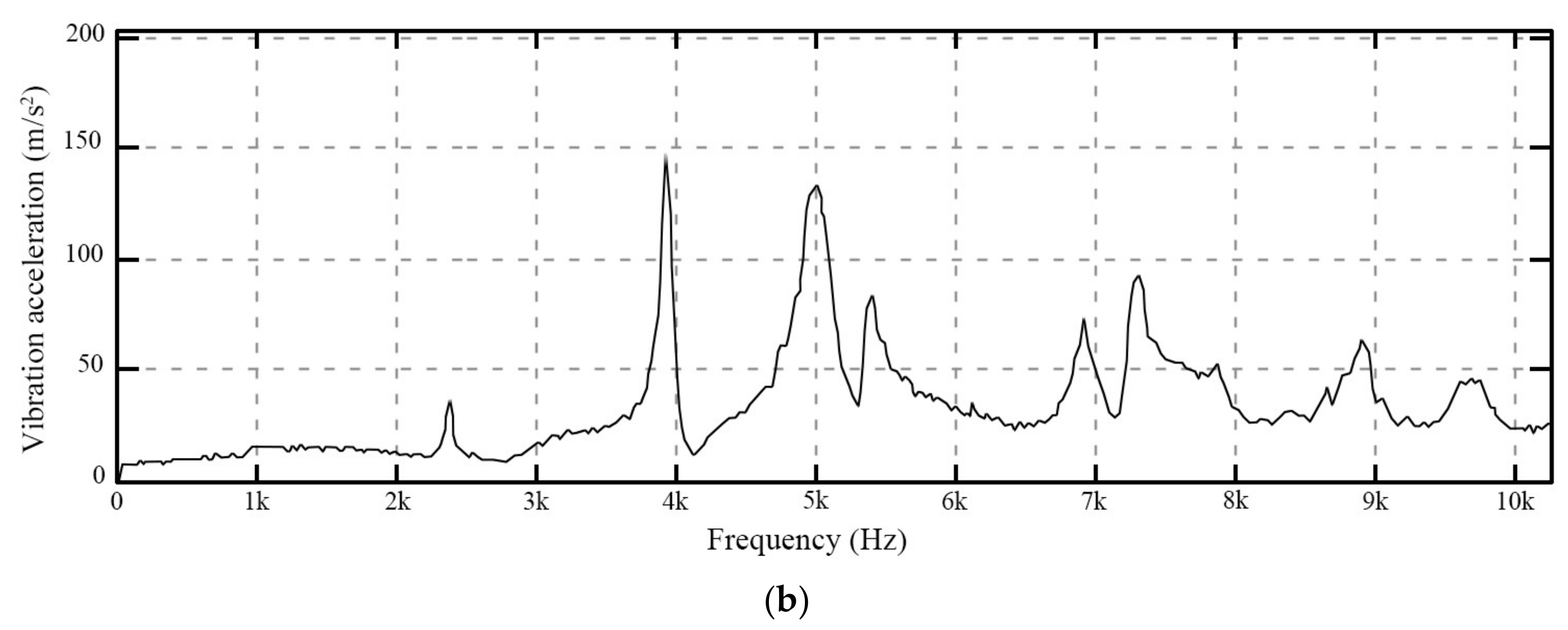
The time domain waveform of the cavitation chamber vibration acceleration was recorded in the laboratory and analysed using the FFT (fast Fourier transform). The corresponding cavitation power spectrum is shown in Figure 8.
3. Slotting Effect of the SOWJ
3.1. Depressurising Effect of the Slotting
The depressurising space is provided for the coal-rock mass by utilising the rock-breaking characteristics of the SOWJ [17,18], cutting the coal along the radial direction of the boreholes to form disk-shaped slots. The numerical simulation software FLAC-3D (FLAC-3D5.0, ITASCA, Minneapolis, MN, USA) was used to study the depressurisation caused by the slotting, and analyse the effectiveness of the process [19].
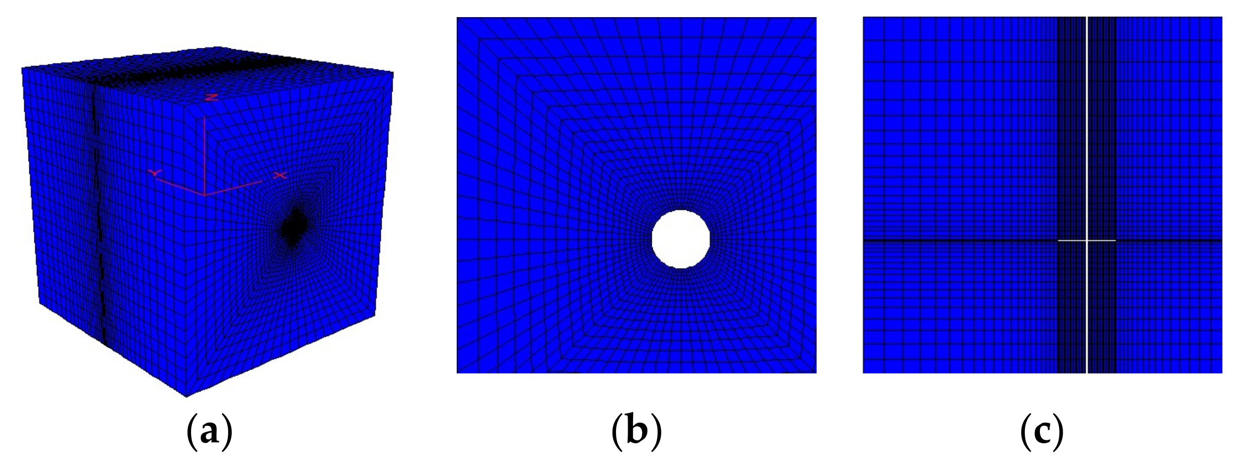
Simulating the slot depressurising effect is a three-dimensional (3D) spatial problem; hence, a 3D model of 15 m × 15 m × 15 m was established. The X direction was the coal seam horizontal direction, the Y direction was the tunnelling direction, perpendicular to the coal seam in the horizontal plane, and the Z direction was the vertical direction. The borehole ran through the entire model along the Y axis. The slotting cavity, shaped by the jets, was located at the centre of the model (Figure 9).
The mechanical parameters of the coal are important factors in the slotting simulation. The density, bulk modulus, shear modulus, friction angle, cohesion, and dilatancy angle of the coal mass are the main parameters defined by the FLAC 3D software using the Mohr-Coulomb model. As this research has universal significance, the measured averages of the parameters are provided in Table 2.
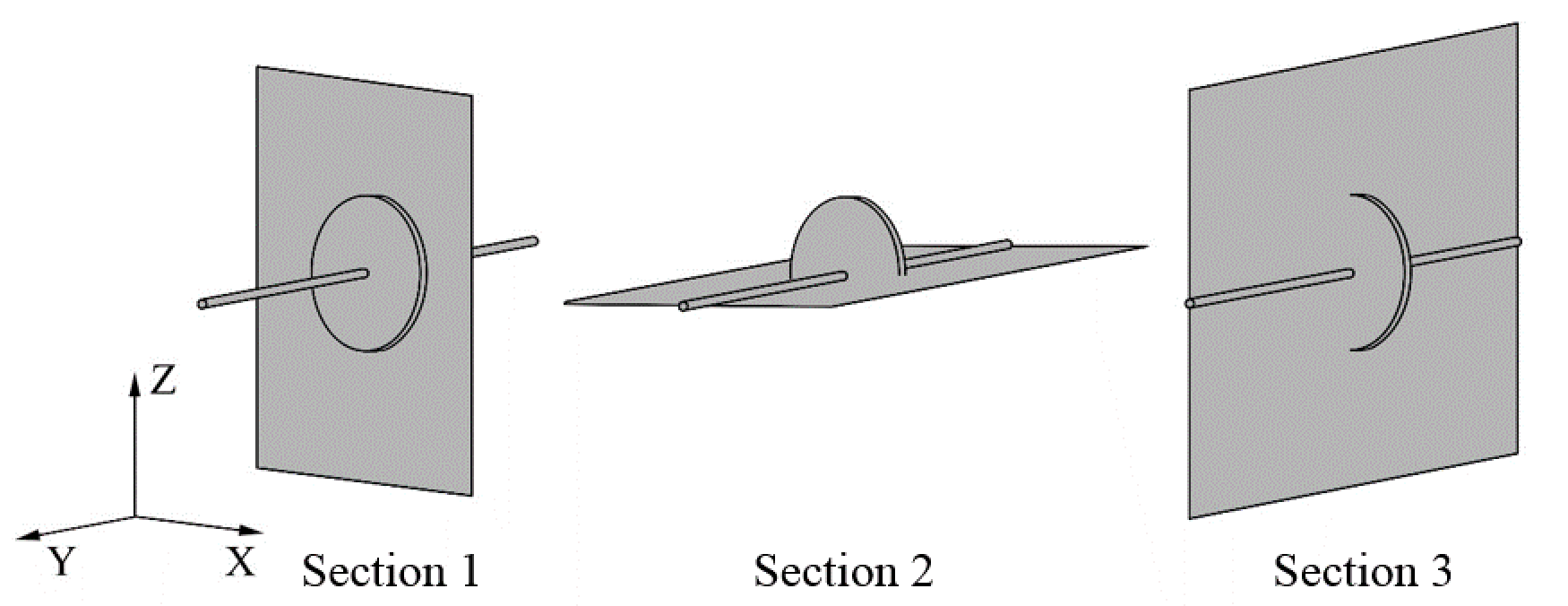
To analyze the depressurising effect, the designed depth of the coal mass was 400 m, the slotting depth was 1 m, and the slotting width was 0.05 m per hole. To better represent the depressurising effect of the slotting, three cross-sections were defined: the section where the vertical drilling axis went through the centre of the slot was defined as Section 1, the horizontal section as Section 2, and the vertical section as Section 3, as shown in Figure 10.
In Figure 11a–c, the stress in the X direction decreased from the centre of the hole slot radially toward the X and Y directions. The stress in the Y direction decreased outward elliptically along the Y direction with the hole slot as the centre. The stress distributions of the Z direction in both the Y and Z direction were similar to those of the X direction: the stress remained in its original state in the area far from the hole and near the edges of the model. In Figure 11d–f, positive values appeared in the vicinity of the hole walls, indicating tensile stress. The value there was much higher than in the other directions because the radial groove area was larger than the axial area so that the largest degree of depressurisation and the most obvious stress drop were in the Y direction. Near the edge of the model, the stresses in the X, Y, and Z directions decreased to 7.6, 9.3, and 8.3 MPa, respectively, corresponding to decreases of 39.49%, 25.95%, and 20.72%, clearly demonstrating the depressurisation effect.
3.2. Formation of the Fracture Field of the Slots
After the slotting, with the gradual release of stress around the slot, the stress is redistributed, increasing the stress in the rock around the crack; this increases the stress difference between the crack zone and the surrounding rock, which causes further cracking and the expansion of cracks in some directions. The gradual accumulation of coal damage causes new tensile shear fractures. Since the slot depth is much larger than the slot width and the radial area is larger than its axial area, a depressurisation surface is formed in the axial direction of the slotting hole. As a result, the coal (defining Unit body 1 as a unit of coal mass on the depressurisation surface) is subjected to less load due to the depressurisation. The load difference on the coal mass between the before- and after-depressurisation states destroys the balance of the force system, where part of the difference can only be sustained by the coal mass farther from the hole (Unit body 2 is defined as a unit in the coal mass far away from the hole). The remaining strength of Unit body 2 after hardening and softening continues to decline as the depressurisation continues. Since Unit body 2 is farther than Unit body 1 from the depressurisation surface, the interior of Unit body 2 is damaged later and less. The yield limit, toughness, and peak strength of the coal mass, under tri-axial compressive stress, are proportional to the size of the lateral load. Unit body 2 is compressed in three directions and its lateral pressure is greater than that of Unit body 1, while its strength limit and the residual strength are higher. Until this stress is transferred to a certain position in the coal mass, the peak strength limit there, after hardening, is greater than the maximum load of the coal body subjected to the tri-axial compression, i.e., the coal body can withstand the load. At this moment, a new force balance is established and the stress transfer stops, as does the destruction caused by the depressurisation of the surrounding coal mass.
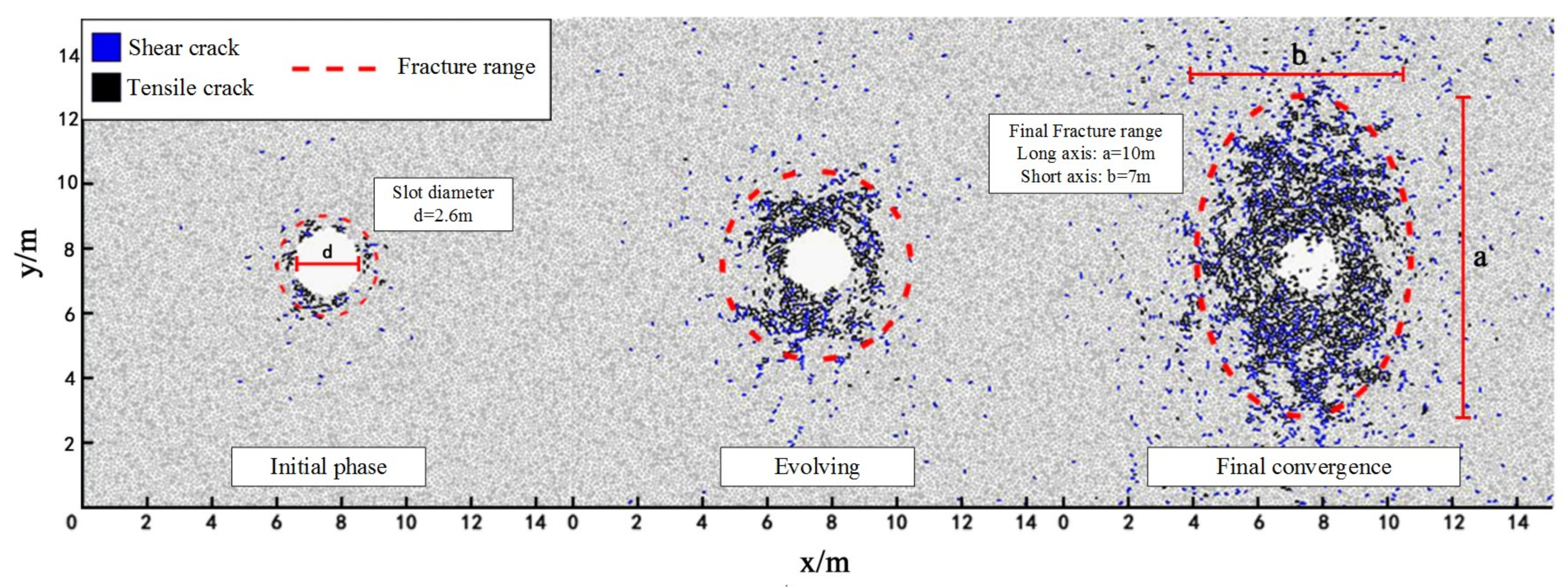
To analyse the evolution of the coal in the fracture around the slot, PFC2D software (PFC2D3.10, ITASCA, Minneapolis, MN, USA) was used to simulate this process. A 14 × 14-m two-dimensional particle flow model was established. The model consisted of 42,418 bonds and 16,334 particles. The coal parameters were the same as those in Section 3.1. The model was loaded by displacement with a vertical stress of 10.46 MPa and a horizontal stress of 12.94 MPa. After reaching stress equilibrium, the delete command was used to form a 2.6-m-diameter disk, simulating a high-pressure water jet slot, in the centre of the model.
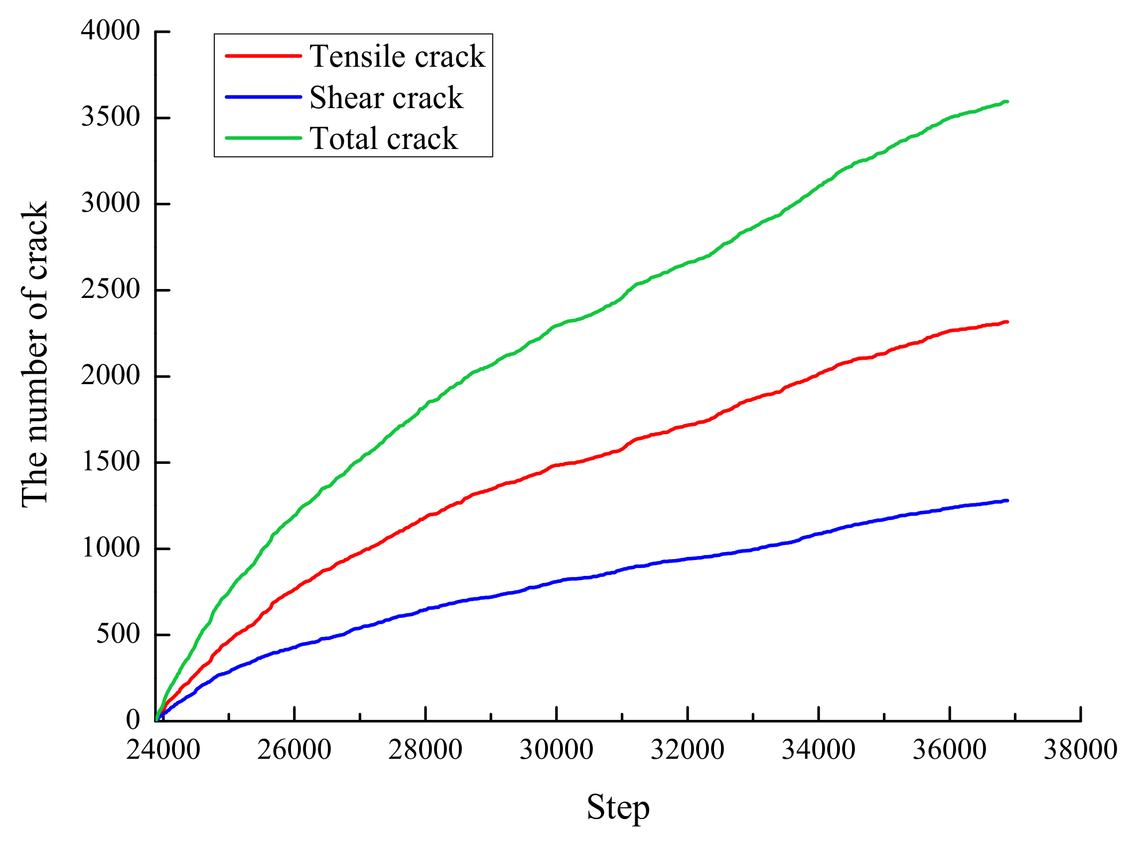
As the number of simulation steps increased, the fractures caused by the depressurisation developed gradually. Tensile and shear cracks were generated when the bond broke due to stretching or rotation, and shearing, respectively. The rate of crack development decreased with the number of loading steps and the number of cracks tended to settle as the stress changed gradually. The number of fractures in the evolution process is shown in Figure 12. After the final convergence, the fractures extend around the disk (Figure 13), forming an oval fracture ring of 10 m in the vertical direction and 7 m in the horizontal direction.
4. Permeability-Increasing Mechanism of the SOWJ Slotting
The SOWJ slotting process increases and expands the coal mass stress field and fracture field. The permeability and gas flow increase as a result of the coupling of multiple factors [20,21].
4.1. Gas Flow Changes in the Slots
After SOWJ slotting, the borehole-exposed coal mass changes from the initial cylinder to a disk-shaped slot [22]. The gas flow from one unit of coal is considered as a single steady flow. Under single stable flow conditions, the gas emission does not change with time, but mainly depends on the difference between the original gas pressure in the coal seam and the gas pressure at the exposed coal surface. The gas emission per unit of exposed coal area can be described as:
where —coal seam permeability coefficient, ; —permeability of the coal seam, m2; —dynamic gas viscosity, Pa s; —standard atmospheric pressure, MPa; —the square of the gas pressure, MPa2; = .
For a single drill hole, the increment of the coal mass exposure after water jet slotting is:
where —increment of coal mass exposure area; —water jet slotting radius; —borehole radius; —water jets slotting width.
Therefore, after slotting by water jets in the coal mass, the gas emission increment (only from the gas flow) is:
4.2. Changes of Coal Permeability
The change in the stress field leads to changes in the mining fracture field, which in turn leads to changes in the porosity [23]. Eventually, the permeability of the coal mass changes dynamically. During this process, the change of the effective stress has an important influence on the dynamic evolution of the permeability [24]; the permeability is exponentially related to the effective horizontal stress. The dynamic change of the permeability is:
where is the original permeability, in units of ; is the fracture volume compression coefficient, in MPa−1; and is the effective horizontal stress.
Therefore, with the depressurisation of the slot-surrounding coal mass after the jet slotting, the increase of permeability of the surrounding coal is conducive to gas flow and the permeability of the coal mass.
4.3. Gas Desorption Enhanced by the Vibration of the SOWJs
Recent studies showed that vibrational stimulation of coal samples increases the desorption capacity of gas-bearing coal [25]. After applying vibration to the coal mass, the fracture structure in the coal slot changed, while the internal energy of the coal and the temperature increased, thus affecting gas desorption in the coal. Jet slotting generates impact vibration (at the same frequency of the self-excited jets) and produces the cavitation sonic vibration effect. Both processes affect the coal mass to promote coal gas desorption. Cavitation number is the physical quantity that assesses the cavitation capability. With a reverse relationship with how intense the cavitation phenomenon is, it can be calculated by:
As shown, is the cavitation number, Pi is the system’s pump pressure (the inlet pressure of the cavity), P0′ is the cavity’s confining pressure, and Pv is the saturated vapor pressure of the water.
We use the vapor pressure under 35 °C as the calculated value of this experiment. The saturated vapor pressure in this temperature is 0.0059 MPa, with which we get different cavitation numbers under different pump pressures and the cavity’s confining pressures, as shown in Table 3.
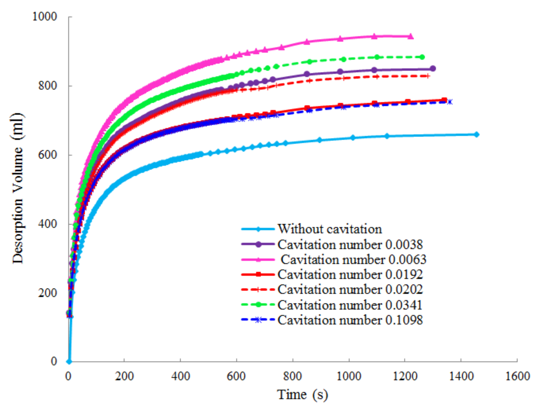
In this study, the effect of gas desorption under different cavitation values was examined experimentally under different cavitation numbers: without cavitation and with cavitation numbers 0.0192, 0.0063, 0.0038, 0.1098, and 0.0202. The coal gas desorption amount and rate over time were analyzed (Table 4). The gas desorption volume curve with time is shown in Figure 14.
The experimental results show that the desorption and the desorption rate have similar trends under conditions of no cavitation sonic vibration and different cavitation numbers. Initially, the desorption rate increased sharply with time, then the growth rate gradually decreased and the desorption value finally stabilised. The initial high coal gas desorption rate and high desorption volume accounted for nearly 80% of the final desorption amount. The gas desorption amount under the cavitation sonic vibration condition was greater than that without cavitation.
5. Field Experiment
To verify the effect of SOWJ slotting on coal permeability, a field extraction experiment was carried out.
5.1. Study Site Descroption
Location: Zhongliangshan South Mine 140NEC4-C5 Extraction Roadway. The maximum gas pressure in the coal seam was 4.7 MPa and the gas content was 74.61~121.24 m3/t.
Reference hole (#1): located 80 m south of 140NEC5 Shimen. Azimuth: 102°, dip: 18°, hole depth: 36 m. Coal seam K10 lies at a depth of 22 m with a thickness of 1.4 m; coal seam K9 is 34.2 m deep and is 0.9 m thick. The diameter of the final hole was 75 mm.
High-pressure water jet slotting hole (#2): located 40 m south of 140NEC5 Shimen. Azimuth: 102°, dip: 18°, hole depth: 33 m. Coal seam K10 lies at a depth of 20.4 m with a thickness of 2.4 m and coal seam K9 lies at a depth of 31 m with a thickness of 0.9 m. The final hole was 75 mm in diameter.
5.2. Experiment Design
Influence Range Test
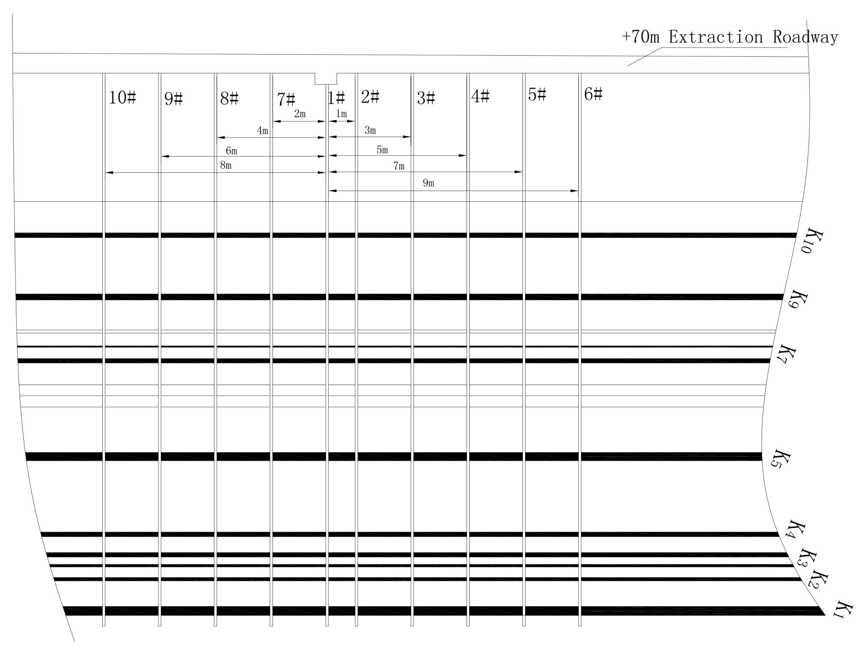
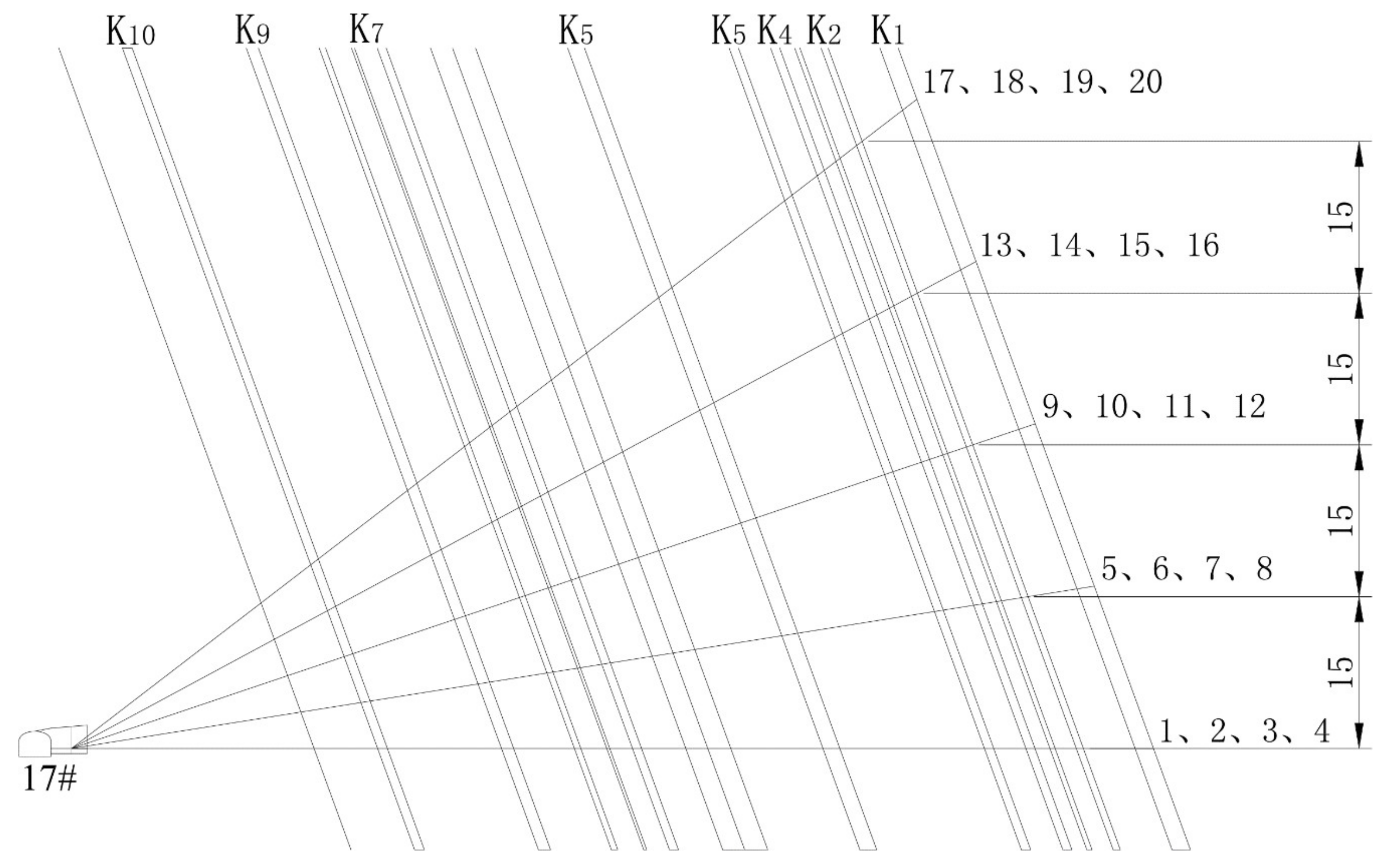
In order to determine the distance between holes, the influence range of single SOWJ drill hole was tested. Combined with the surrounding rock conditions and gas geological conditions of a +70 m level roadway in South Mine, the final drainage radius was determined and the holes were arranged on the #17 drilling field. In this experiment, nine drill holes were arranged, consisting of one SOWJ drill hole (#5), and eight inspection drill holes (#1, #2, #3, #4, #6, #7, #8, and #9). The layout of all drill holes is shown in Figure 15 and Figure 16.
The drill hole diameter was chosen as 75 mm, and the opening positions of the drill holes were selected at the complete rock site. The sequence of drill hole construction is as follows: the first step is to drill eight inspection drill holes (#1, #2, #3, #4, #6, #7, #8, #9), as shown in Figure 16. After that, the SOWJ drill hole (#5) is drilled when the gas pressure is stable. The detailed parameters of the drill holes are shown in Table 5.
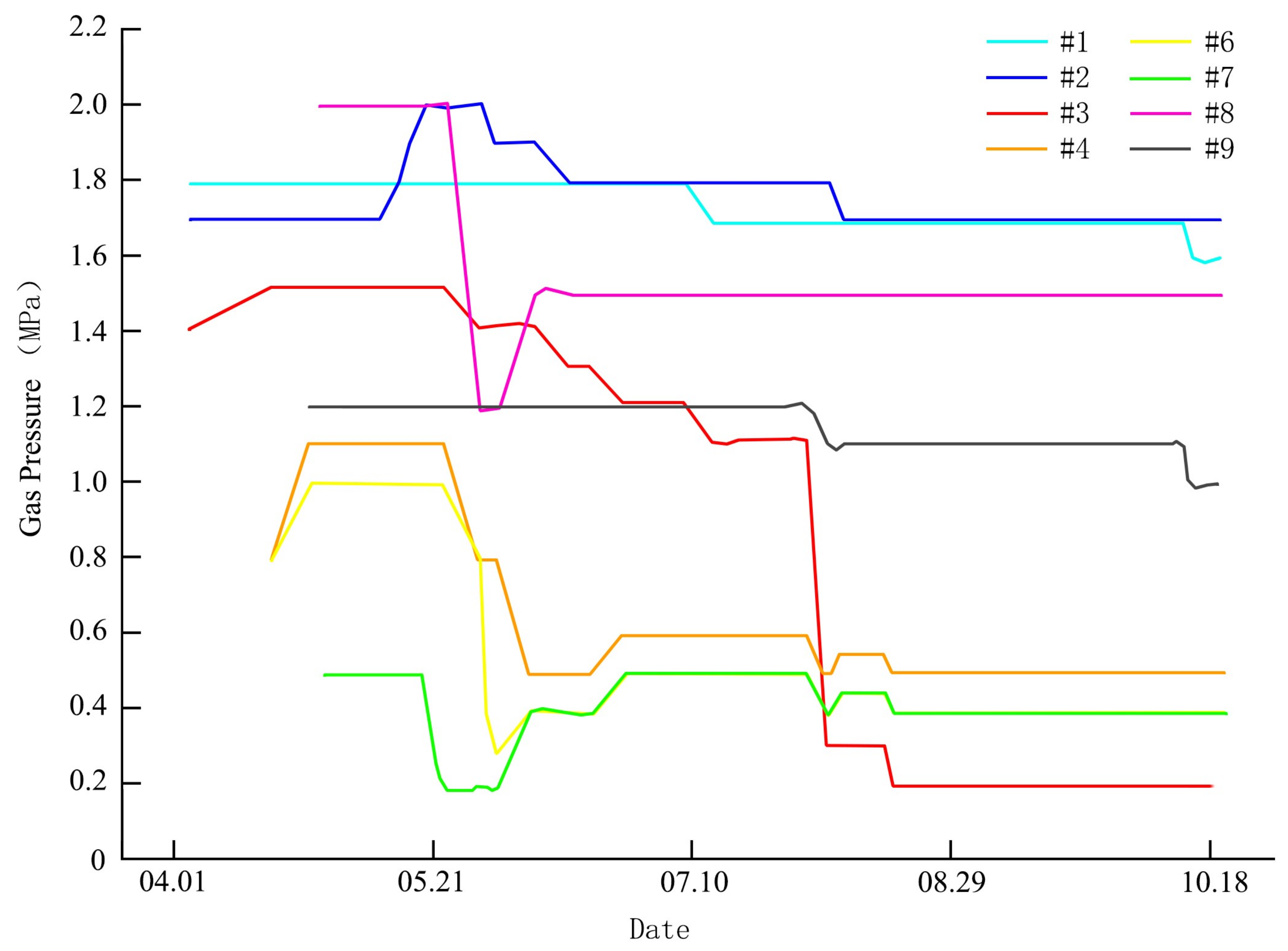
After the SOWJ drill hole started exhausting, gas pressure data of the inspection drill holes were collected and are summarised in Figure 17. Gas pressure of #4, #6, and #7 near the SOWJ hole (#5 hole) decreased quickly below 0.74 MPa (according to “Coal Mine Safety Regulation” of China, the gas pressure reached or over 0.74 MPa is the standard to identify whether a coal seam has a prominent danger, therefore, it is also used to judge the effectiveness of the extraction). For slotting without exhausting, the natural gas discharge radius is up to 4 m. After 117 days extraction of the SOWJ drill hole (#5 hole), #3 hole’s gas pressure reduced to below 0.74 MPa, whose distance to the #5 hole was 5 m. In addition, the gas pressure in the 9 m area was reduced by more than 10%. The data validates that the effective extraction radius reached 5 m after the slotting, and the gas influence radius was at least 9 m.
According to the field test results, the effective influence radius of the high-pressure water jet slotting in the extraction lanes of coal seam 140NEC4-C5 in South Zhongliangshan exceeded 5 m. Combined with the surrounding rock conditions and geological gas conditions, the final spacing of the extraction holes was determined as 10 m. The extraction hole layout is shown in Figure 18 and Figure 19; 127 boreholes were drilled and the total footage was 12,018.93 m.
5.3. Extraction Data Analysis
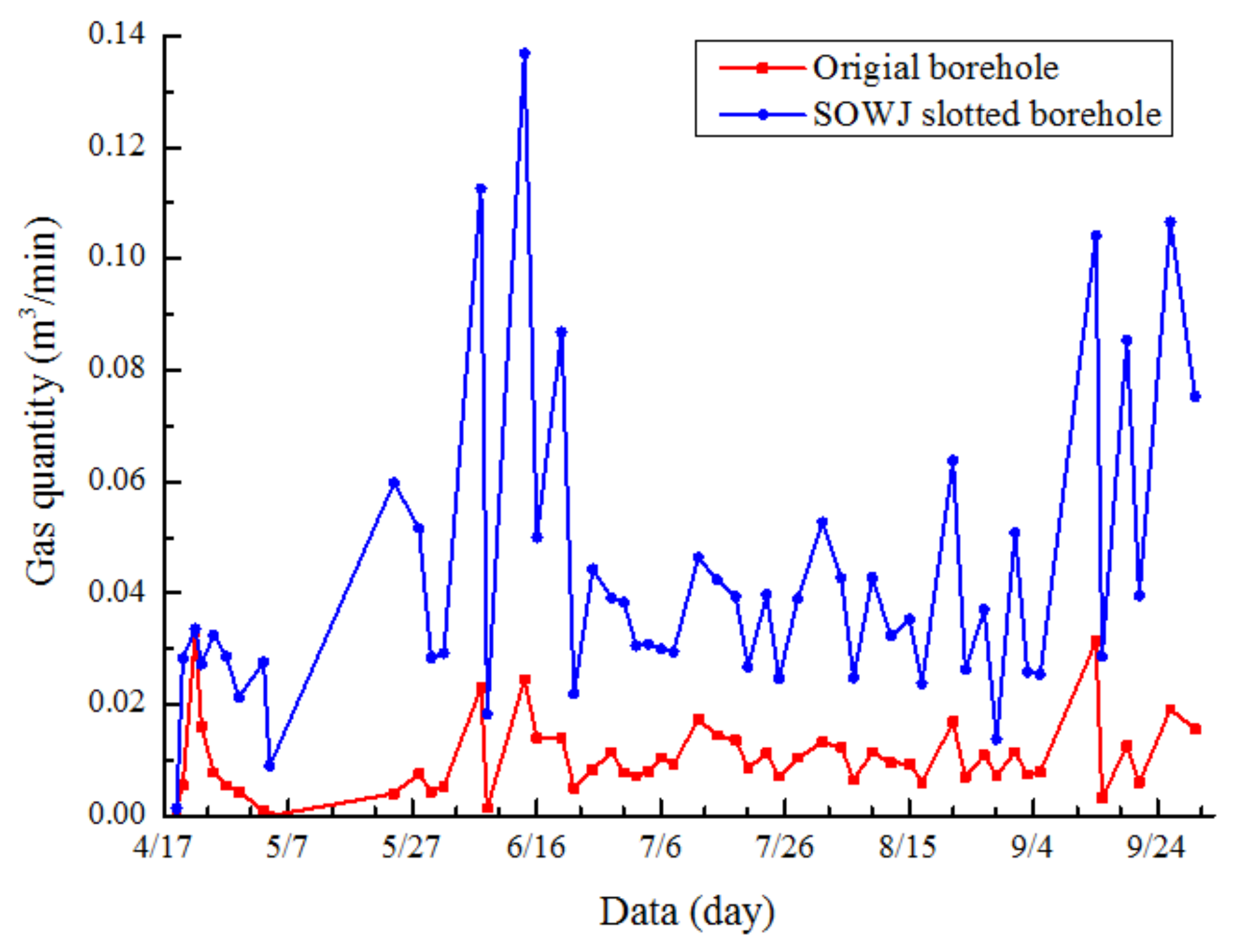
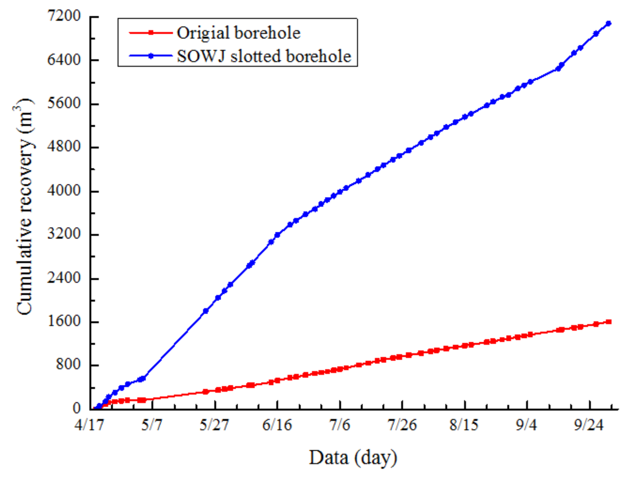
According to statistics of extraction data recorded over a period of nearly six months, the extracted gas from the original borehole totaled 1606 m3, while the gas extraction from the SOWJ slotted borehole was 7081 m3, which is 4.41 times that of the former. The average standard scalar volume was 0.01 m3/min, while that of the SOWJ slotting boreholes was 0.042 m3/min, which is 4.2 times that of the former (Figure 20 and Figure 21).
The data shows that the SOWJ slotting significantly improved the gas drainage effect compared with that of the conventional slotting method. The total gas drainage volume and the standard extraction scalar volume increased significantly, indicating that the application of SOWJ slotting in high gas-bearing and low permeable coal seams can effectively improve the gas extraction efficiency.
6. Conclusions
- (1)
- SOWJ slotting can be applied in high-efficiency CBM mining by concurrently increasing the fracture network, improving the permeability of the coal, and enhancing gas desorption.
- (2)
- The characteristics of the SOWJ were studied: by impacting on the coal-rock mass, SOWJ induces the formation of the erosion–peeling zone, fragmentation zone, and distal conical crack zone on the rock. The jet induces vibration of the coal mass at its own frequency and the simultaneous cavitation sonic vibrating effect can also generate coal mass vibration.
- (3)
- The impact of the jet on the coal mass was studied: the slots and fractures created by the jet can release elastic energy within the rock, causing depressurisation which changes the coal mass stress field. The redistribution of the stress induces the initial cracks (at the tips of the slots) to develop and expand, and the gradual accumulation of damage around the slots generates new fractures; thus, perforated fracture networks are formed.
- (4)
- The formation of slots increases the exposure area of the coal mass and the gas flow passages, affecting the gas flow pattern. The coal permeability is exponentially related to the effective horizontal stress; the vibration characteristics and the cavitation sonic vibrating effect can improve gas desorption and increase gas emission.
- (5)
- By stimulating the jet slotting and multifactor coupling processes, we demonstrated a positive cycle of coal mass depressurisation, fracture evolvement → permeability increase, gas desorption and emission → gas extraction (depressurised gas) → coal mass depressurisation, fracture evolvement. This cycle greatly improved the rate of CBM extraction.
- (6)
- To verify the SOWJ slotting effect, a field test was performed at the Zhongliangshan South Mine. The extracted gas from the conventional borehole totalled 1606 m3, while the gas extraction from the SOWJ slotted borehole was 7081 m3, which is 4.41 times that of the former. The average standard scalar volume was 0.01 m3/min, while that of the SOWJ slotting boreholes was 0.042 m3/min, which is 4.2 times of the former. Compared with conventional extraction, the extraction utilising SOWJ slotting substantially improved the total gas drainage volume and the standard extraction scalar volume. Thus, SOWJ slotting can increase the efficiency of CBM extraction.
Acknowledgments
The work is jointly supported by the National Key Basic Research Program of China (No. 2014CB239206), the National Natural Science Foundation of China (No. 5162500292), and the Program for Changjiang Scholars and Innovative Research Team in University of China (No. IRT13043).
Author Contributions
Chengwei Liu, Binwei Xia and Yiyu Lu conceived and designed the experiments; Binwei Xia performedthe experiments; Chengwei Liu and Binwei Xia analysed the data; Chengwei Liu wrote the paper.
Conflicts of Interest
The authors declare no conflict of interest.
References
- Lau, H.C.; Li, H.; Huang, S. Challenges and opportunities of coalbed methane development in China. Energy Fuels 2017, 31, 4588–4602. [Google Scholar] [CrossRef]
- Li, L.; Lei, Y.; Zhao, L. Study on the Optimization of the Industrial Structure in a Mining Economic Region: Taking Carbon Emissions as a Restriction. Minerals 2015, 5, 203–220. [Google Scholar] [CrossRef]
- Moore, T.A. Coalbed methane: A review. Int. J. Coal Geol. 2012, 101, 36–81. [Google Scholar] [CrossRef]
- Li, H.; Lau, H.C.; Huang, S. Coalbed Methane Development in China: Engineering Challenges and Opportunities. In Proceedings of the SPE/IATMI Asia Pacific Oil & Gas Conference and Exhibition, Jakarta, Indonesia, 17–19 October 2017. [Google Scholar]
- Zhao, Q.; Sun, F.; Li, W. Theory and Practice of Coal-Bed Methane Exploration and Development; Petroleum Industry Press: Beijing, China, 2011; pp. 5–11. [Google Scholar]
- Jin, K.; Cheng, Y.; Wang, W. Evaluation of the remote lower protective seam mining for coal mine gas control: A typical case study from the Zhuxianzhuang Coal Mine, Huaibei Coalfield, China. J. Nat. Gas Sci. Eng. 2016, 33, 44–55. [Google Scholar] [CrossRef]
- Yin, G.; Li, M.; Wang, J.G. Mechanical behavior and permeability evolution of gas infiltrated coals during protective layer mining. Int. J. Rock Mech. Min. Sci. 2015, 80, 292–301. [Google Scholar] [CrossRef]
- Lu, Y.; Ge, Z.; Yang, F.; Xia, B.; Tang, J. Progress on the hydraulic measures for grid slotting and fracking to enhance coal seam permeability. Int. J. Min. Sci. Technol. 2017, 27, 867–871. [Google Scholar] [CrossRef]
- Yan, F.; Lin, B.; Zhu, C. Cross-borehole hydraulic slotting technique for preventing and controlling coal and gas outbursts during coal roadway excavation. J. Nat. Gas Sci. Eng. 2015, 26, 518–525. [Google Scholar]
- Zhu, W.C.; Gai, D.; Wei, C.H. High-pressure air blasting experiments on concrete and implications for enhanced coal gas drainage. J. Nat. Gas Sci. Eng. 2016, 36, 1253–1263. [Google Scholar] [CrossRef]
- Zhao, L.; Qin, Y.; Cai, C. Control of coal facies to adsorption-desorption divergence of coals: A casefrom the Xiqu Drainage Area, Gujiao CBM Block, North China. Int. J. Coal Geol. 2017, 171, 169–184. [Google Scholar] [CrossRef]
- Sun, Z.; Li, X.; Shi, J. A semi-analytical model for drainage and desorption area expansion during coal-bed methane production. Fuel 2017, 204, 214–226. [Google Scholar] [CrossRef]
- Cook, S.S. Erosion by Water-Hammer. Proc. R. Soc. Lond. Ser. A 1928, 119, 481–488. [Google Scholar] [CrossRef]
- Soyama, H.; Yanauchi, Y.; Sato, K.; Ikohagi, T.; Oba, R.; Oshima, R. High-speed observation of ultrahigh-speed submerged water jets. Exp. Therm. Fluid Sci. 1996, 12, 411–416. [Google Scholar] [CrossRef]
- Pianthong, K.; Zakrzewski, S.; Behnia, M.; Milton, B.E. Supersonic liquid jets: Their generation and shock wave characteristics. Shock Waves 2002, 11, 457–466. [Google Scholar] [CrossRef]
- Marcon, A.; Melkote, S.N.; Castle, J. Effect of jet velocity in co-flow water cavitation jet peening. Wear 2016, 360, 38–50. [Google Scholar] [CrossRef]
- Zou, Q.; Lin, B.; Liu, T.; Zhou, Y.; Zhang, Z.; Yan, F.-Z. Variation of methane adsorption property of coal after the treatment of hydraulic slotting and methane pre-drainage: A case study. J. Nat. Gas Sci. Eng. 2014, 20, 396–406. [Google Scholar] [CrossRef]
- Summers, D.A.; Henry, R.L. Water jet cutting of sedimentary rock. J. Pet. Technol. 1972, 24, 797–802. [Google Scholar] [CrossRef]
- Hu, S.; Zhang, A.; Feng, G. Impact of Coalbed Incidence Angle on Methane Enrichment Zone in Longwall Gob. Minerals 2017, 7, 166. [Google Scholar] [CrossRef]
- Pan, J.N.; Hou, Q.L.; Ju, Y.W.; Bai, H.L.; Zhao, Y.Q. Coalbed methane sorption related to coal deformation structures at different temperatures and pressures. Fuel 2012, 102, 760–765. [Google Scholar] [CrossRef]
- Liu, J.S.; Chen, Z.W.; Elsworth, D.; Miao, X.X.; Mao, X.B. Linking gas-sorption induced changes in coal permeability to directional strains through a modulus reduction ratio. Int. J. Coal Geol. 2010, 83, 21–30. [Google Scholar] [CrossRef]
- Shen, C.M.; Lin, B.Q.; Zhang, Q.Z.; Yang, W.; Zhang, L.J. Induced drill-spray during hydraulic slotting of a coal seam and its influence on gas extraction. Int. J. Min. Sci. Technol. 2012, 22, 785–791. [Google Scholar] [CrossRef]
- Tan, X.-H.; Li, X.-P.; Liu, J.-Y.; Zhang, L.-H.; Fan, Z. Study of the effects of stress sensitivity on the permeability and porosity of fractal porous media. Phys. Lett. A 2015, 379, 2458–2465. [Google Scholar] [CrossRef]
- Jiang, Y.D.; Li, Y.; Cui, Y.Z. Experimental study on characteristics of coal reservoir permeability under acoustic wave. J. China Coal Soc. 2017, 42, 154–159. [Google Scholar]
- Jiang, Y.D.; Song, X.; Liu, H.; Cui, Y. Laboratory measurements of methane desorption on coal during acoustic stimulation. Int. J. Rock Mech. Min. Sci. 2015, 78, 10–18. [Google Scholar] [CrossRef]
Figure 1.
Schematic diagram of a self-oscillatory pulse gas–liquid jetting nozzle: (1) upstream nozzle; (2) upstream impinging wall; (3) oscillation chamber; (4) downstream nozzle.
Figure 1.
Schematic diagram of a self-oscillatory pulse gas–liquid jetting nozzle: (1) upstream nozzle; (2) upstream impinging wall; (3) oscillation chamber; (4) downstream nozzle.

Figure 2.
Device schematic of pressure measurement system. 1—Water tank; 2—Strainer; 3—Plunger pump; 4—Pressure gauge; 5—Surge tank; 6—Overflow valve; 7—Turbine flowmeter; 8—Test board; 9—Nozzle; 10—Pitot tube; 11—Pressure transmitter; 12—Data recording card and computer; 13—Display monitor.
Figure 2.
Device schematic of pressure measurement system. 1—Water tank; 2—Strainer; 3—Plunger pump; 4—Pressure gauge; 5—Surge tank; 6—Overflow valve; 7—Turbine flowmeter; 8—Test board; 9—Nozzle; 10—Pitot tube; 11—Pressure transmitter; 12—Data recording card and computer; 13—Display monitor.

Figure 3.
Pressure measurement system.

Figure 4.
Pressure curves of the pulsed water jets.

Figure 5.
Diagram showing the water jet impact on a solid surface: stress and shock wave generation and propagation.
Figure 5.
Diagram showing the water jet impact on a solid surface: stress and shock wave generation and propagation.

Figure 6.
High-resolution images of coal-rock specimens showing the effect of the SOWJ.

Figure 7.
Crack patterns observed outside and inside the rock samples impacted by water jets.

Figure 8.
Cavitation sonic vibration in the time and frequency domain; pump pressure 15 MPa, confining pressure 0.5 MPa. (a) Time domain waveform of the vibration acceleration; (b) Vibration power spectrum.
Figure 8.
Cavitation sonic vibration in the time and frequency domain; pump pressure 15 MPa, confining pressure 0.5 MPa. (a) Time domain waveform of the vibration acceleration; (b) Vibration power spectrum.


Figure 9.
The geometry of the model showing the borehole and grid pattern: (a) 3D View; (b) Elevation view; (c) Overhead view.
Figure 9.
The geometry of the model showing the borehole and grid pattern: (a) 3D View; (b) Elevation view; (c) Overhead view.

Figure 10.
Illustration of the three cross-sections used in the analysis.

Figure 11.
Stress distribution of a single slot: (a) Stress distribution profiles of sections 1 in the X directions; (b) Stress distribution profiles of sections 2 in the Y directions; (c) Stress distribution profiles of sections 3 in the Z directions; (d) Stress distribution profiles of sections 1 in the Z directions; (e) Stress distribution profiles of sections 2 in the X directions; (f) Stress distribution profiles of sections 3 in the Y directions.
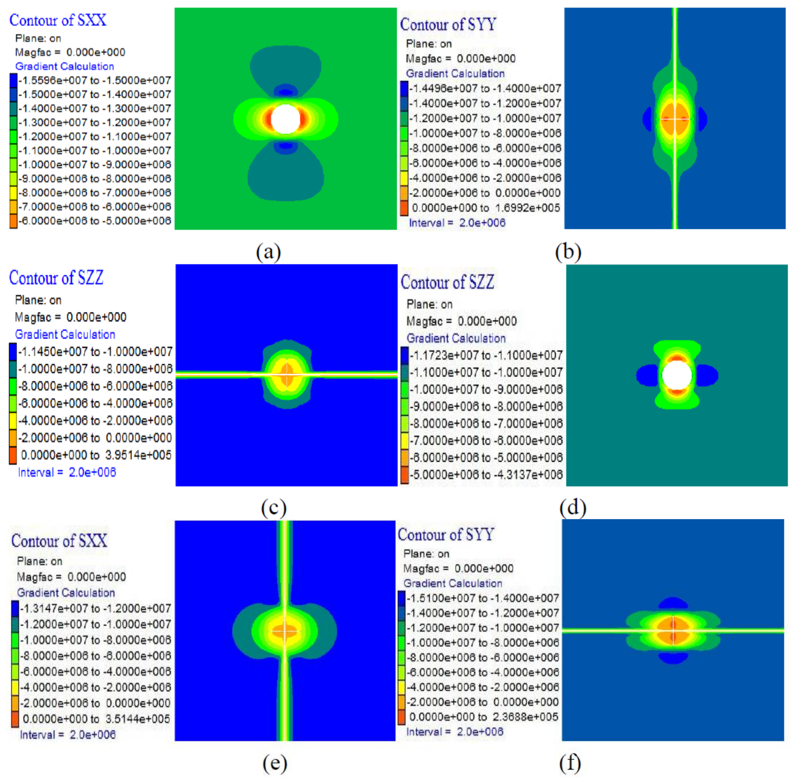
Figure 12.
Slotting simulation results showing the number of cracks in the model under loading.

Figure 13.
Simulation results showing evolution of coal fractures under two-dimensional stress.

Figure 14.
Gas desorption volume curve with time for various cavitation numbers.

Figure 15.
Extraction of roadway position.
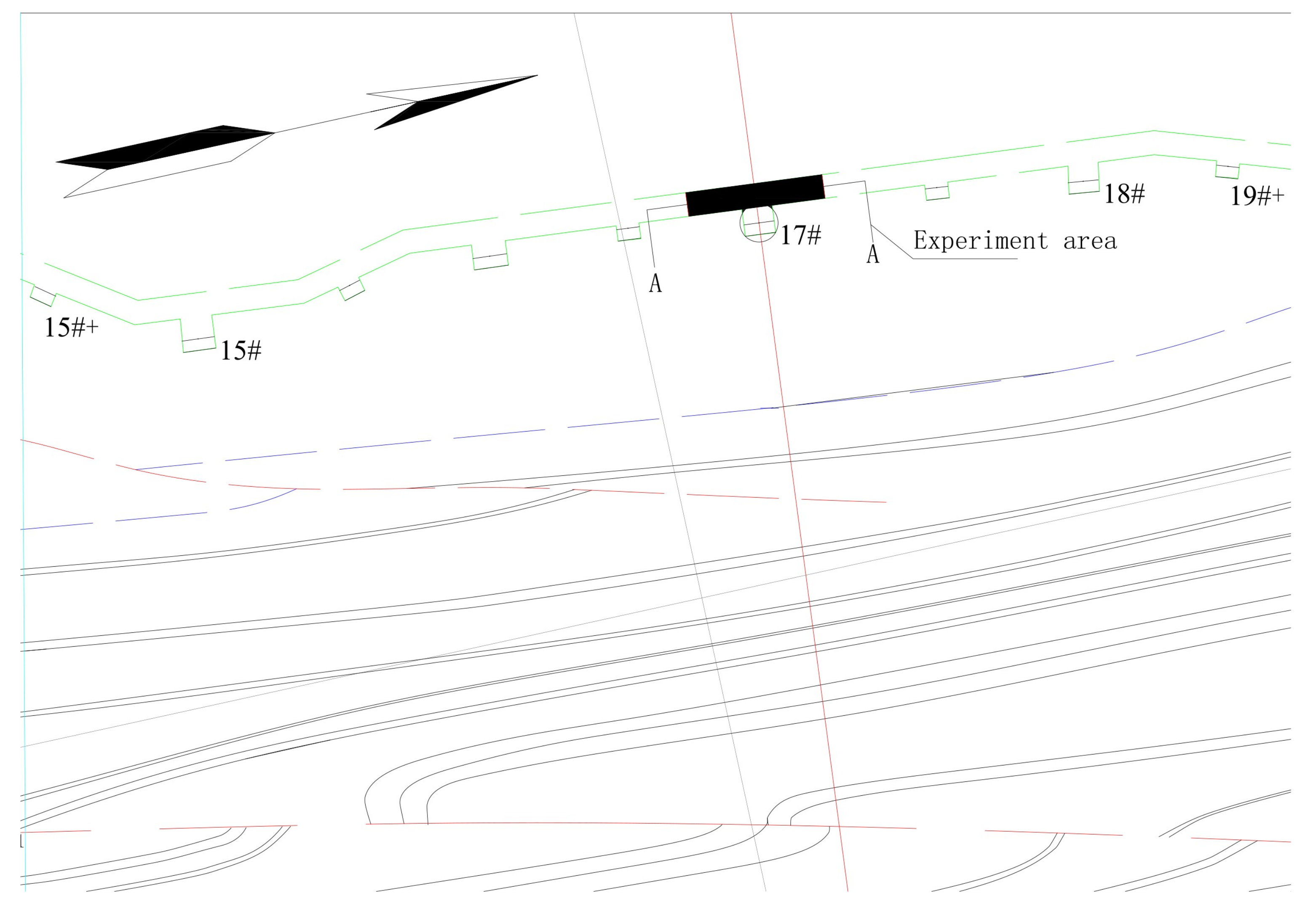
Figure 16.
Layout of the drill holes.

Figure 17.
Pressure change curve of inspection drill holes.5.2.2. Extraction Experiment.

Figure 18.
Borehole layout at the Zhongliangshan South Mine.
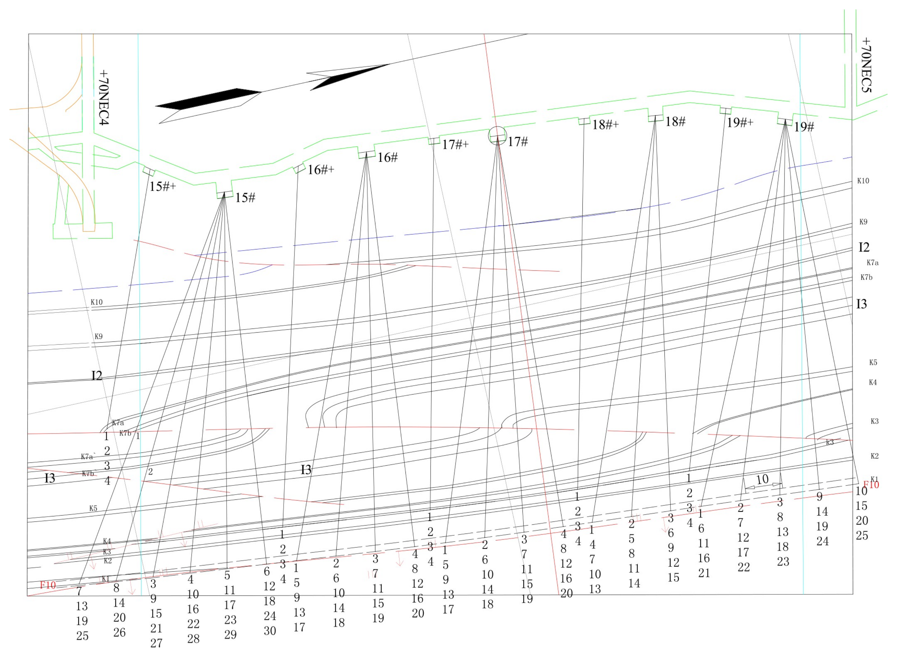
Figure 19.
Enlarged view of borehole section layout.

Figure 20.
Accumulative gas extractions of standard and SOWJ slotting boreholes.

Figure 21.
Gas quantity of standard and SOWJ slotting boreholes.

Table 1.
The physical and mechanical properties of the sandstone sample.
| Bulk Density | Secant Young’s Modulus | Poisson’s Ratio | Acoustic Speed | Brazilian Test Strength | Uniaxial Compressive Strength |
|---|---|---|---|---|---|
| kg m−3 | GPa | m/s | MPa | MPa | |
| 2382 | 54.3 | 0.25 | 4316 | 5.55 | 68 |
Table 2.
The mechanical parameters of the coal samples.
| Density (kg/m3) | Bulk Modulus (GPa) | Shear Modulus (GPa) | Friction Angle (°) | Cohesion (MPa) | Dilatancy Angle (°) | Tensile Strength (MPa) |
|---|---|---|---|---|---|---|
| 1450 | 1.67 | 1.25 | 18 | 1.07 | 12 | 0.5 |
Table 3.
Cavitation Numbers in Different Pump Pressures and Cavity’s Confining Pressures.
| Pump Pressure | 5 MPa | 10 MPa | 15 MPa | 20 MPa | 25 MPa | |
|---|---|---|---|---|---|---|
| Confining Pressure | ||||||
| 0.1 MPa | 0.0192 | 0.0095 | 0.0063 | 0.0047 | 0.0038 | |
| 0.2 MPa | 0.0404 | 0.0198 | 0.0131 | 0.0098 | 0.0078 | |
| 0.3 MPa | 0.0626 | 0.0303 | 0.0200 | 0.0149 | 0.0119 | |
| 0.4 MPa | 0.0857 | 0.0411 | 0.0270 | 0.0201 | 0.0160 | |
| 0.5 MPa | 0.1098 | 0.0520 | 0.0341 | 0.0253 | 0.0202 | |
Table 4.
Gas Desorption Volume and Rate.
| Experiment Scheme (Cavitation Number) | Test Targets | Time/s | |||||||
|---|---|---|---|---|---|---|---|---|---|
| 10 | 20 | 50 | 100 | 200 | 400 | 600 | When Experiment Ends | ||
| With No Cavitation Sonic Vibration | Desorption Volume/mL | 200 | 263 | 363 | 455 | 534 | 590 | 619 | 665 (1555 s) |
| Desorption Rate/(mL/s) | 14.00 | 5.21 | 2.65 | 1.43 | 0.53 | 0.18 | 0.12 | 0.017 | |
| 0.0192 | Desorption Volume/mL | 217 | 303 | 435 | 533 | 618 | 679 | 708 | 760 (1340 s) |
| Desorption Rate/(mL/s) | 16.06 | 7.56 | 3.11 | 1.39 | 0.53 | 0.19 | 0.13 | 0.046 | |
| 0.0063 | Desorption Volume/mL | 245 | 364 | 523 | 638 | 743 | 839 | 887 | 945 (1220 s) |
| Desorption Rate/(mL/s) | 20.07 | 10.22 | 3.56 | 1.71 | 0.76 | 0.33 | 0.24 | 0.0026 | |
| 0.0038 | Desorption Volume/mL | 230 | 326 | 465 | 572 | 673 | 746 | 798 | 849 (1300 s) |
| Desorption Rate/(mL/s) | 17.84 | 8.25 | 3.31 | 1.61 | 0.67 | 0.32 | 0.24 | 0.014 | |
| 0.1098 | Desorption Volume/mL | 215 | 301 | 432 | 532 | 616 | 677 | 713 | 754 (1360 s) |
| Desorption Rate/(mL/s) | 15.89 | 7.56 | 3.05 | 1.51 | 0.58 | 0.23 | 0.11 | 0.036 | |
| 0.0341 | Desorption Volume/mL | 238 | 360 | 500 | 608 | 710 | 791 | 834 | 885 (1260 s) |
| Desorption Rate/(mL/s) | 19.44 | 10.35 | 2.8 | 1.64 | 0.72 | 0.30 | 0.25 | 0.0063 | |
| 0.0202 | Desorption Volume/mL | 224 | 319 | 459 | 566 | 667 | 748 | 788 | 830 (1280 s) |
| Desorption Rate/(mL/s) | 17.18 | 8.25 | 3.43 | 1.75 | 0.82 | 0.37 | 0.12 | 0.0083 | |
Table 5.
Detailed parameters of the drill holes.
| Number of Drill Hole | Azimuthal Angle | Dip Angle | Length of Drill Hole | Ending Positions | The Distance to #5 SOWJ Drill Hole |
|---|---|---|---|---|---|
| 1 | 102 | 202 | 127 m | Roof of K1 | 9 m |
| 2 | 102 | 202 | 126 m | Roof of K1 | 7 m |
| 3 | 102 | 202 | 126 m | Roof of K1 | 5 m |
| 4 | 102 | 202 | 126 m | Roof of K1 | 3 m |
| 5 | 102 | 202 | 121 m | Roof of K1 | - |
| 6 | 102 | 202 | 87 m | Roof of K1 | 2 m |
| 7 | 102 | 202 | 126 m | Roof of K1 | 4 m |
| 8 | 102 | 202 | 125 m | Roof of K1 | 6 m |
| 9 | 102 | 202 | 123 m | Roof of K1 | 8 m |
© 2018 by the authors. Licensee MDPI, Basel, Switzerland. This article is an open access article distributed under the terms and conditions of the Creative Commons Attribution (CC BY) license (http://creativecommons.org/licenses/by/4.0/).
Share and Cite
MDPI and ACS Style
Liu, C.; Xia, B.; Lu, Y. Coalbed Methane Extraction Using the Self-Oscillating Water Jet Slotting Method. Energies 2018, 11, 897. https://doi.org/10.3390/en11040897
AMA Style
Liu C, Xia B, Lu Y. Coalbed Methane Extraction Using the Self-Oscillating Water Jet Slotting Method. Energies. 2018; 11(4):897. https://doi.org/10.3390/en11040897
Chicago/Turabian StyleLiu, Chengwei, Binwei Xia, and Yiyu Lu. 2018. "Coalbed Methane Extraction Using the Self-Oscillating Water Jet Slotting Method" Energies 11, no. 4: 897. https://doi.org/10.3390/en11040897
Note that from the first issue of 2016, this journal uses article numbers instead of page numbers. See further details here.