1. Introduction
Nowadays, diesel-engine synchronous generation is a primary shipboard power system (SPS). However, with the tendency of reducing the use of traditional fossil fuels and limiting the ship large-tonnage, which is increasing quickly with the size of ships and their associated electrical power equipment, the development of new energy supplies instead of diesel is an urgent demand with regard to the quick development of shipboard electric power systems [
1,
2]. Photovoltaic (PV) generation utilizing solar energy is one of the best choices for power supply on ships due to its excellent economy and high efficiency. However, the features of PV such as intermittency and limited development area, has limited solar-powered ships working within a short navigation range with rather high costs [
3]. Hence, the PV–diesel-battery hybrid power system is a promising power supply system in comparison with traditional power generation systems and can enhance fuel economy and the continuity of power supply, reduce marine pollution, and improve grid power quality, system stability, and flexibility [
4,
5,
6].
Onboard AC electrical power system may be categorized as an islanded AC microgrid [
7], which causes numerous power quality issues. One prominent problem is the voltage/frequency swing during the start-up and braking of sailing caused by the substantial rapid load of high-power propulsion changing, which will increase power losses and reduce SPS stability, reliability, and security [
8,
9]. Chinese SPS standards stipulate that the vessel’s grid voltage and frequency variation range must be −10~+6% and −5~+5% respectively [
10]. Meanwhile, presently there is extensive use of emerging diode rectifiers, pulsed power-electronics loads, non-linear loads, and asymmetrical loads in the SPSs, which arouse a series of power quality issues of harmonics, unbalanced voltage, as well as dc-offset voltage from scaling errors in the grid voltage measurement of grid current performance [
11,
12]. When the PV generation technique is applied on a ship for the shipboard PV–diesel-battery hybrid AC power system, a PV inverter is essential to convert PV battery direct currents into alternating currents that are synchronous to the grid. However, as the power capacity of a PV inverter is much lower than that of a diesel-engine synchronous generator for laying area limitations, the PV inverter has less grid-voltage regulation capability and is suitable for the current injection method by means of a diesel-engine synchronous generator working in standalone mode as a slack bus. Hence, how the vessel’s fundamental frequency sequence voltage can be quickly and accurately tracked under such adverse grid conditions has become a critical concern with respect to shipboard PV–diesel-battery hybrid power systems.
Usually, a phase-locked loop (PLL) in a synchronous reference frame (SRF-PLL) is used to detect the phase angle, amplitude, and frequency of the grid voltage in three-phase systems for Park transformation as a phase detector (PD). However, its performance deteriorates when the grid is non-sinusoidal for harmonics, unbalanced, or with dc bias. Its
d-axis and
q-axis voltage components in the SRF are no longer constant but contain disturbances oscillating at integer multiples of fundamental frequency [
13]. Hence, the phase error is inaccurate, which leads to a detection error. To eliminate harmonic disturbance, various kinds of in-loop and out-loop filter techniques have been proposed. In [
13], a moving average filter (MAF) PLL was proposed by passing the dc component and completely blocking the frequency components of integer multiples of 1/
Tw (
Tw is MAF window length) in Hertz, but considerably slowed down its dynamic response. Differential MAF-PLL was proposed by increasing the open-loop bandwidth and significantly improving the dynamic performance of MAF-PLL [
14]. In [
15], a notch filter PLL with a band-rejection filter was introduced. It significantly attenuated signals within a narrow band of frequencies, passed all other frequency components with negligible attenuation, and minimized the phase delay in the PLL control loop. Moreover, a delayed signal cancellation PLL [
16] and a PLL based on a second-order generalized integrator (SOGI), known as SOGI-PLL [
17], were reported. For eliminating unbalance influence, an enhanced PLL [
18,
19] and a PLL based on a generalized integrator (GI) and SOGI-PLL [
17,
20] have been reported. The enhanced PLL (EPLL) consists of a frequency-adaptive filter whose frequency follows the fundamental frequency of the grid. The quartz-crystal-based PLL (QPLL) was designed by using the estimation of the in-phase and quadrature-phase amplitudes and the frequency of the fundamental input signal. Finally, the SOGI-PLL has a GI as the main block that generates in-phase and quadrature-phase sinusoidal components of the input signal. As voltage/frequency swing, a structure simplification of the SOGI-PLL that replaces the PLL with a frequency-locked loop based on a SOGI (SOGI-FLL) was introduced in [
21]. The FLL estimates the frequency of the input signal and is used to tune the SOGI, with the grid voltage frequency. In [
22], a multiple SOGI was introduced that used a cross-feedback network consisting of multiple SOGIs to reject the harmonics from the grid. The multi-SOGI-FLL was designed to achieve a fast response, but its response can be distorted by subharmonics in the input signal. In a word, all PLL techniques mentioned here were designed for one or two specific power quality issues but cannot be used directly on a vessel with severe grid conditions.
Due to two poles of SOGI transfer function, SOGI can be used as a proportional-resonant (PR) controller in an
αβ-frame to fully follow input sinusoidal waves with zero steady-state error [
23,
24]. It is equivalent to SRF-PLL in the
dq-frame as a proportional-integral (PI) controller according to frame transformation [
25]. Meanwhile, its in-phase and quadrature-phase outputs have the characteristics of frequency selection and a low-pass filter (LPF), respectively. Hence, it can be used as the PLL, the voltage/current PR controller, the filter, and so on for its harmonics attenuation, simple configuration, and flexibility. In this paper, SOGIs in different functions were used for a specific shipboard PV–diesel-battery hybrid power system for grid voltage tracking. In this hybrid SPS, the diesel-engine synchronous generator worked in standalone mode as a slack bus, where the diesel governor and synchronous excitation system maintained the grid voltage frequency and amplitude of the shipboard PV–diesel-battery hybrid power system. The PV–battery inverter acts as an active and reactive power (PQ) bus to inject the desired active and reactive powers given by the power management system (PMS) to the grid. Hence, grid voltage tracking is necessary for the PV inverter voltage reference generator. A SOGI-based frequency-locked loop (SOGI-FLL) is one way to capture the voltage and frequency at voltage/frequency swing and filter harmonics but is invalid for addressing a vessel’s issues of low-frequency(LF) harmonics, including subharmonics, unbalanced voltage, and dc-offset voltage. For the subharmonic/dc-offset non-attenuation limitation of SOGI quadrature-phase output, a SOGI-based structure with prefilter, a dc-offset block, and a positive sequence extractor (SOGI-FDE)was proposed consisting of three SOGIs using in-phase output with subharmonic/dc-offset attenuation. Therefore, an adaptive grid voltage tracking schematic, SOGI-FDE-FLL, with a quick and accurate SPS integrating a SOGI-FDE and a SOGI-FLL was devised. This new voltage tracking schematic was composed of four SOGIs. The former unit was for pre-filtering LF harmonics, for blocking subharmonics/dc bias, and for obtaining an ideal positive α-axis sequence component, whereas the latter unit was for the adaptive tracking of a vessel’s grid voltage amplitude and frequency in voltage/frequency swing.
This paper is organized as follows.
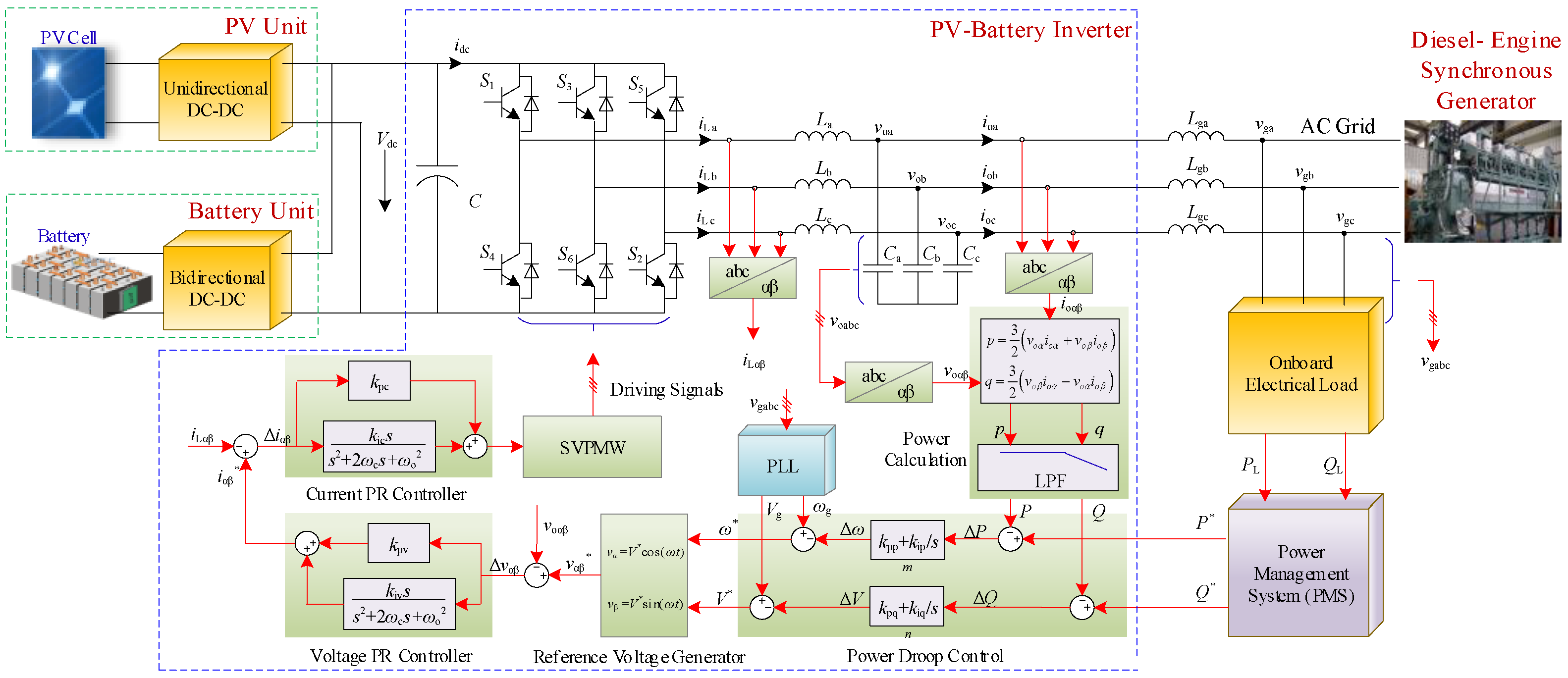
Section 2 describes the shipboard PV–diesel-battery hybrid power system configuration and the PV–battery inverter control strategy.
Section 3 analyzes in detail the SOGI and the SOGI-FLL and reveals SOGI’s limitations and problems under a given vessel’s adverse grid conditions.
Section 4 proposes the SOGI-FDE structure, and on this basis an adaptive voltage tracking structure, SOGI-FDE-FLL, which was our method of tracking a vessel’s grid voltage and the key parameters of an optimized design.
Section 5 presents the experimental results to confirm the theoretical analysis presented.
Section 6 presents the conclusion of this work.
4. The Proposed Adaptive Voltage/Frequency Tracking Method Based on SOGIs
A SOGI was considered in this study for its BPF for in-phase output and its LPF for quadrature-phase output. However, when applied to an SPS for voltage tracking, the primary issues were the unbalanced voltage impact on the input signal, the subharmonic and dc-offset impact on the quadrature-phase output signal, and the low-order harmonic impact on the SOGI in-phase output signal.
4.1. The Proposed SOGI-FDE Configuration
The three-phase three-wire system is adopted in most cases for high reliability on the shipboard power supply. Once the three-phase voltage is unbalanced, there are positive and negative sequence voltage terms as shown in Equation (20). Setting
vgαβ as a three-phase grid voltage in the
αβ-frame, the corresponding positive sequence term
can then be expressed as
where
Tαβ is the coordinate transformation (CT) from the
abc-frame to the
αβ-frame, namely,
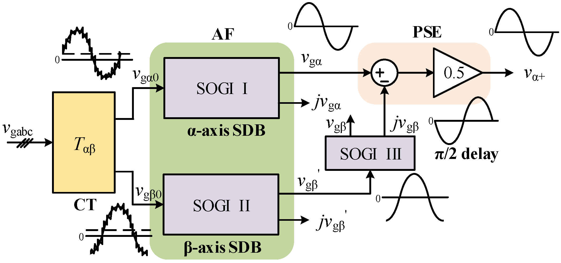
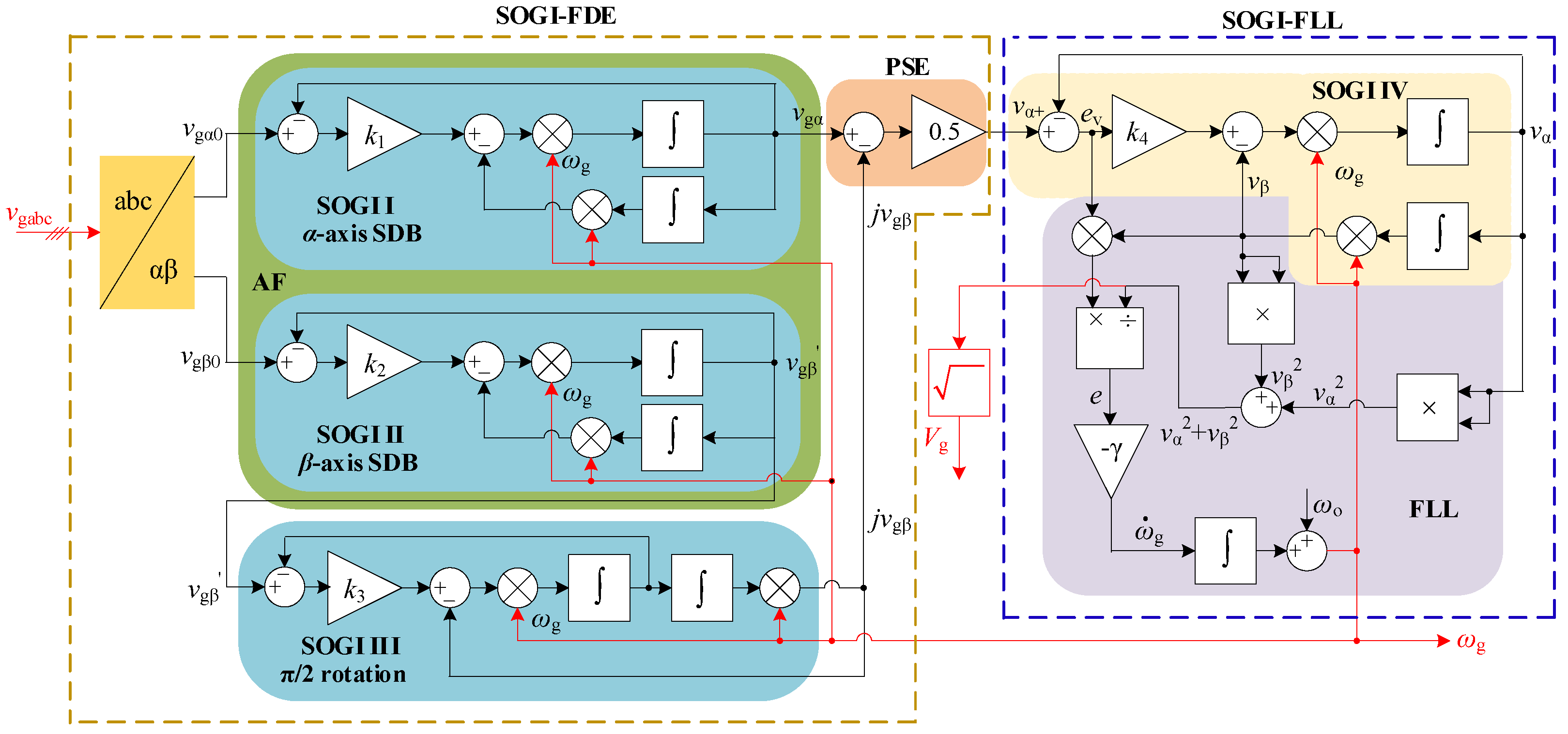
In this paper, to simplify the schematic of the PLL under adverse grid conditions in the SPS, a synthetic SOGI-based structure with prefilter, a dc-offset block, and a positive sequence extractor (SOGI-FDE) as depicted in
Figure 7, is proposed. This structure is composed of a coordinate transformation (CT)
Tαβ for the grid voltage
abc/
αβ-frame transformation and three SOGI units. SOGI I and II, connected to the grid voltage in α- and β-frame components as the in-phase outputs, constitute two active filters (AF) and a subharmonics/dc-bias eliminator for grid voltage in the stationary
α-axis and
β-axis components, respectively, for LF attenuation. Meanwhile, SOGI III, linked to SOGI II, positively rotates the
β-axis component
vgβ’
π/2 for the imaginary unit
j generator of PSE in Equation (25). The PSE unit extracts the positive sequence
α-axis component from the unbalanced three-phase grid voltage.
4.2. Proposed SOGI-FDE-FLL for Vessel’s SPS in Adverse Grid Conditions
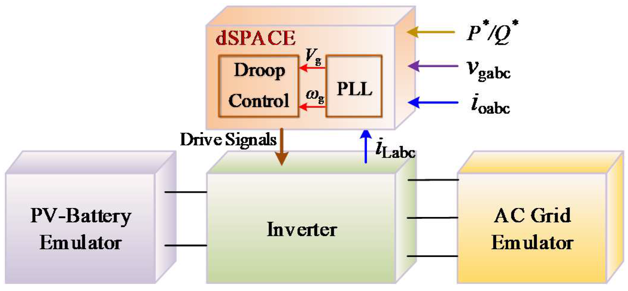
For the mentioned shipboard PV–diesel-battery hybrid power system in
Section 2, the PQ control method was adopted for the PV–battery inverter due to the lower capacity of the photovoltaic battery when compared to a diesel engine on the vessel. The grid-voltage and frequency information are needed to generate a voltage reference for the voltage and current closed-loop control. However, for the vessel’s adverse grid condition of serious voltage/frequency swing, harmonics, unbalanced voltage, subharmonics, and dc bias component, an adaptive grid voltage/frequency tracking method based on SOGIs to a PV–diesel-battery hybrid SPS was proposed, as depicted in
Figure 8. This schematic is composed of SOGI-FDE and SOGI-FLL, named SOGI-FDE-FLL.
In this scheme, the FLL is used only in the α-frame to make the sequence detection adaptive to the grid frequency. The SOGI-FDE unit, for a pre-filter, a subharmonic and dc-offset eliminator and a positive sequence extractor, is connected directly to the vessel’s grid to obtain the positive sequence fundamental voltage vα+ without the subharmonics and dc bias component. From the SOGIs’ characteristics of Equations (5) and (6) and the abc-frame to αβ-frame transformation of Equations (25) and (26), the voltage amplitude, frequency, and phase of vα+ is the a-axis positive sequence voltage in the abc-frame. This was the key opinion of this paper to track vα+ to obtain accurate voltage and frequency estimated values instead of tracking grid voltage vgabc with more power quality problems directly.
The SOGI-FLL unit, a grid voltage/frequency estimator, is used to quickly obtain accurate information of grid voltage and frequency in their serious fluctuations.
Vg, the estimated voltage amplitude, is calculated as the root square of its in-phase and quadrature-phase output, whereas the estimated frequency
ωg is given by an adaptive frequency schematic of an equivalent frequency closed-loop control.
Vg and
ωg subtract the differences of voltage and frequency obtained from
Q-
V and
P-
f droop relationships, respectively, and then reference the voltage generator to form the three-phase reference signal of the voltage/current closed-loop control system as shown in
Figure 1.
In the above proposed schematic, the SOGI-FDE unit is in front of the SOGI-FLL.
vα+, the input signal of SOGI-FLL, is associated with the
vgα and
jvgβ transmitted from the grid α-frame component
vgα0 by SOGI I and from the
β-frame component
vgβ0 by SOGIs II and III for PSE. Meanwhile, it is transmitted through SOGI IV to the in-phase output
vα. Hence, the schematic can be considered as a double-input single-output system. If the damping constant of all the SOGIs are equal, the Laplace transfer function
G1(
s), the ratio of
vg to
vgα0, and
G2(
s), the ratio of
vg to
vgβ0, can be expressed as
where
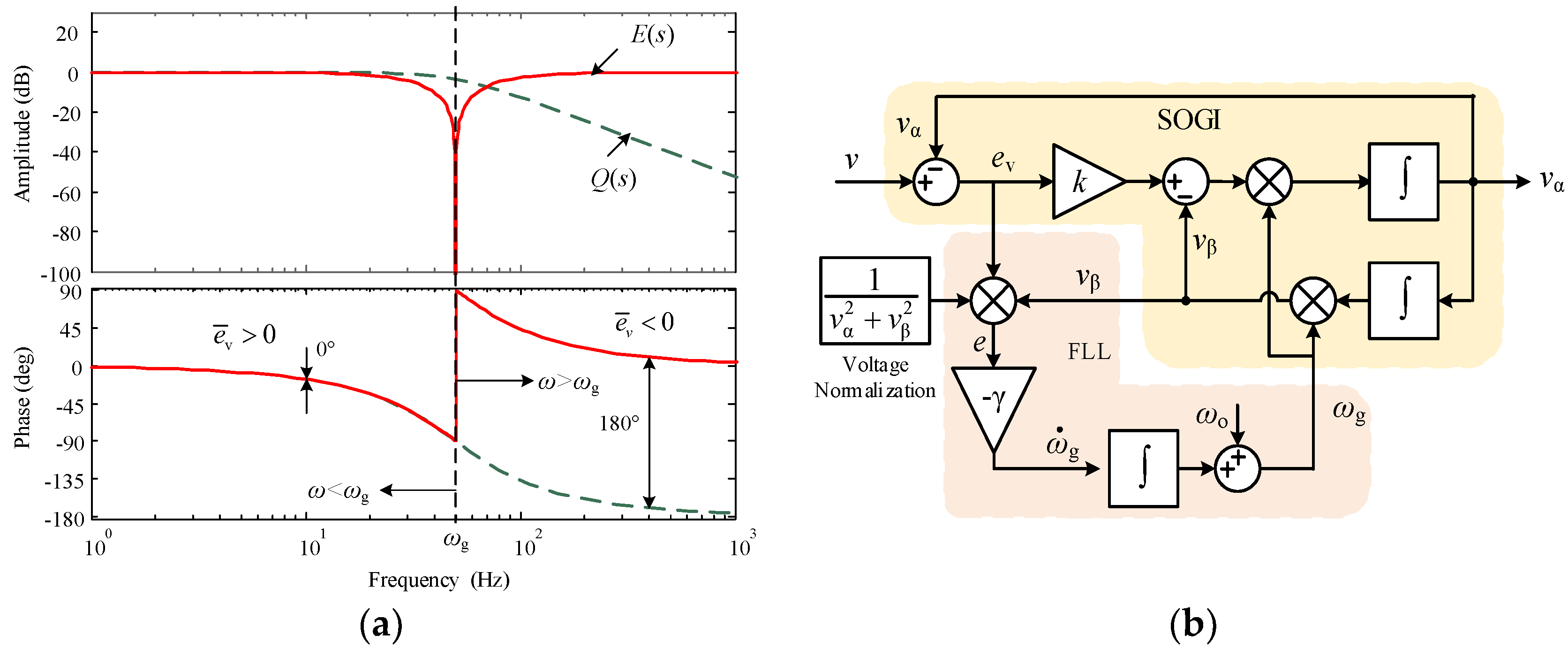
D(
s) and
Q(
s) are the SOGI’s transfer functions of corresponding in-phase and quadrature-phase output to input signals (see Equations (5) and (6)).
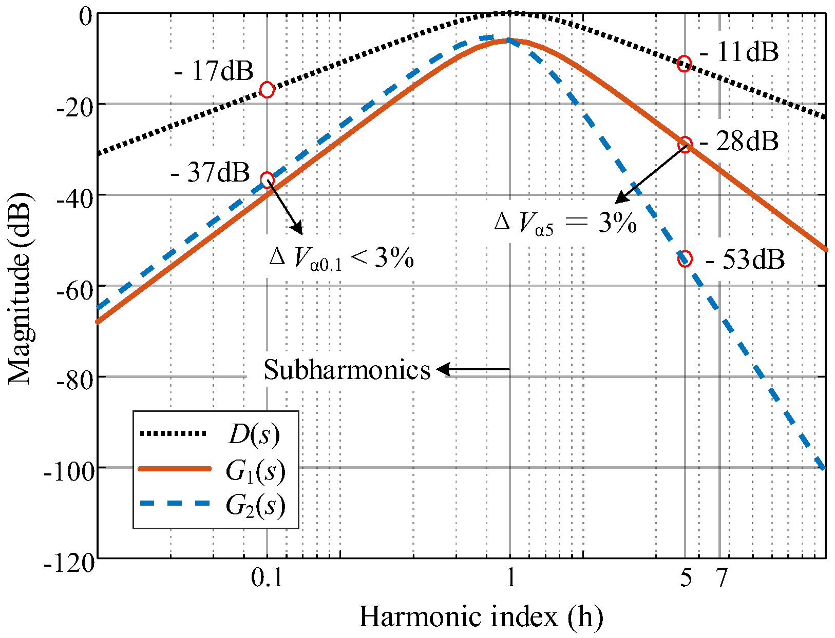
Figure 9 depicts the
D(
s),
G1(
s), and
G2(
s) magnitude plot in LF harmonics with the same damping constants of
k = 1.414 and oscillation frequency of
ωg = 314 rad/s. All of these have the capability of dc bias attenuation.
D(
s) represents the 1st-order SOGI of in-phase output with a narrow BPF, but insufficient LF harmonics suppression at 20 dB per decade slope.
G1(
s) was obtained by the 2nd-order SOGI, where the LF harmonics obtain substantial attenuation at 40 dB per decade slope for an
s-domain of 2 zeros and 2 pairs of left-half poles. The 5th harmonic was reduced to 3%, and 0.1-order subharmonics can be degraded to lower than 3% (see
Figure 9 for illustration).
G2(
s) was composed of the 3rd-order SOGI with the same
G1(
s) in the subharmonic zone and a sharp attenuation to the low-order harmonics at 80 dB per decade slope decrease. Hence, besides the positive sequence extractor from the unbalanced voltage, this proposed schematic has good features of LF harmonics, sharply fading out, including subharmonics and low-order harmonics without a dc bias, which allows this schematic to overcome the limitations of the SOGI’s limitations -mentioned in
Section 3.3.
In all, this proposed voltage/frequency tracking method based on SOGIs has good features regarding subharmonics and dc bias rejection, as well as voltage/frequency capture in grid voltage serious oscillation. This method is thus suitable for a shipboard power system with new energy generation.
4.3. The Parameters Optimization Design of SOGI-FDE-FLL
There were four damping constants in four SOGIs and one error gain in FLL in SOGI-FDE-FLL. The values of those parameters have close relations to the characteristics of the structure.
4.3.1. The Characteristics of Damping Constant in SOGI
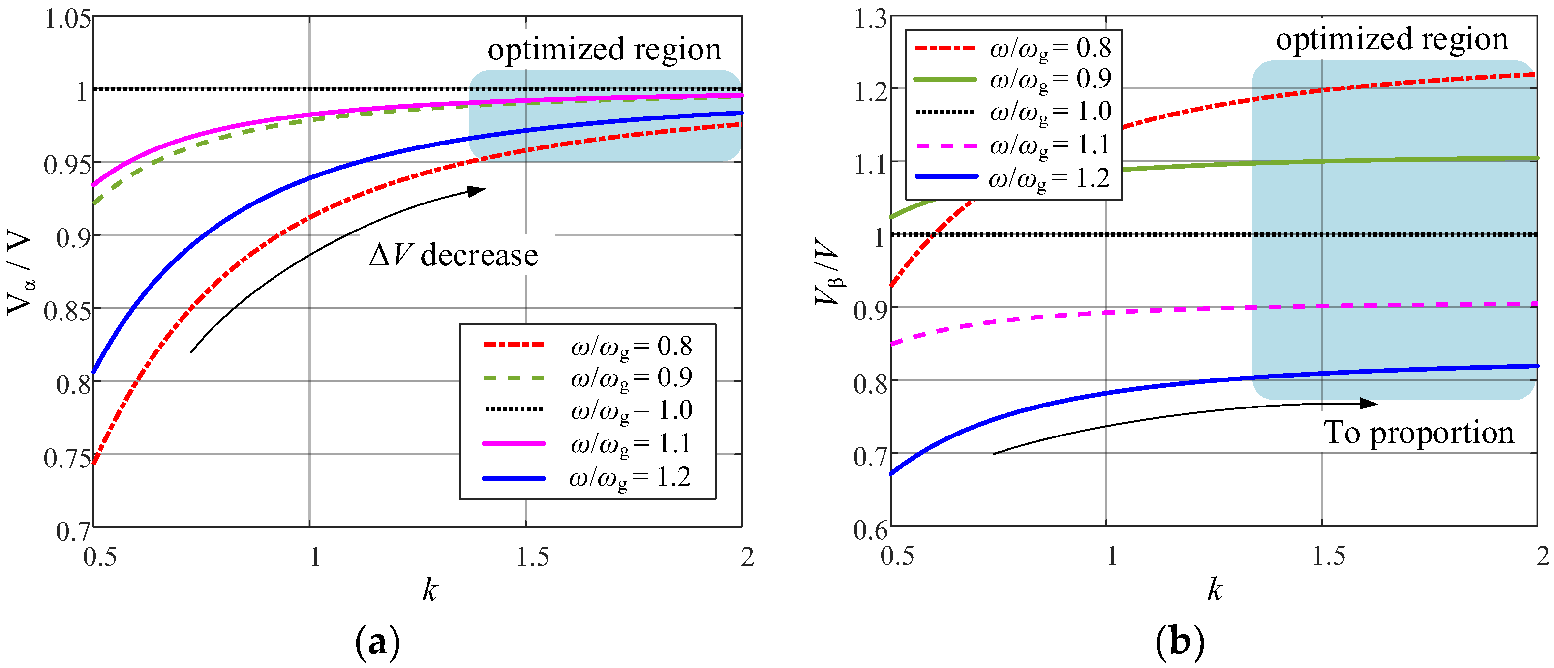
Figure 10 depicts the relationships of the ratios of in-phase voltage amplitude
Vα and quadrature-phase voltage amplitude
Vβ to input voltage amplitude, respectively, with their frequency ratio
ω/
ωg from 0.8 to 1.2 and damping constant
k from 0.5 to 2, obtained from Equations (11)–(14) to emulate the grid voltage/frequency swing. The values of
k have great effects on both the in-phase and quadrature-phase outputs, especially on the former when the input signal amplitude and frequency fluctuate. When
ω is equal to the oscillation frequency
ωg,
Vα and
Vβ are both equal to
V, and at that time, from Equations (13) and (14),
V can be deduced from
which means
ωg is kept equal to
ω, so the estimated amplitude can be obtained from SOGI’s in-phase and quadrature-phase signals.
Moreover, from the input-phase output-voltage curve shown in
Figure 10a, it can be seen that
and
Vα is increasingly smaller with decreasing
k. The higher
k is, the smaller the value of
V minus
Vα is. However, the quadrature-phase output voltage curve shown in
Figure 10b had variation trends different from that shown in
Figure 10a. When the input signal fluctuating with
k was greater than 1,
Vβ/
V and
ω/ωg had approximately linear relations and
Vβ decreased as
ω increased. The higher
k is, the more this linearity improves.
The damping constant can be determined by the voltage variance from
Figure 9, and was replotted to 2D as shown in
Figure 11. Compared to
Vβ,
Vα had less voltage variance. Increasing
k is of benefit for decreasing this variance. On the other hand,
Vβ, as shown in
Figure 10b, has relatively less variance when
k is from 1.0 to 1.5 but tends to have proportional variance to the continuously increasing
k. This linear relationship improves the stability in the transient response and can be expressed as
Above all, the frequency variation of the input signal is the key point of amplitude variance generation in the in-phase and quadrature-phase outputs, and the damping constant is the key parameter for the SOGI unit, which directly affects the two output signals. Increasing the damping constant obviously decreased the amplitude variance of the in-phase output and improved the quadrature-phase output linearity, which is better for the stability of the transient response and voltage/frequency swing.
4.3.2. Three Damping Constants in SOGI-FDE Unit
The damping constant of the SOGI is also in direct relation to the bandwidth of the in-phase signal passing through. The higher the damping constant, the wider the frequency band signal passes through with worse harmonic attenuation; the lower damping constant represents a narrower bandwidth and better frequency selection, but worse stability.
For the proposed schematics of
Figure 8, the inputs of SOGI I and II were directly connected to the grid voltage in the
αβ-frame. Hence,
k1 and
k2, the corresponding damping constants of SOGI I and II, are key to the transmitting voltage bandwidth, letting
k1 =
k2 =
k. The Chinese shipboard power system standard stipulates that the fundamental frequency of the vessel’s grid
fo is (50 ± 5) Hz [
10]. Hence, to ensure that the proposed PLL worked normally across a wide range, the frequency bandwidth Δ
fBW of SOGI I and SOGI II should be set greater than 25 Hz, namely,
Meanwhile, for the dynamic response requirement of the SOGI unit in the SPS, the settling time should be limited to one fundamental period, namely,
from Equation (7).
Hence, for the furthest minimum, the in-phase output variance of SOGI I and II, shown in
Figure 10a, that integrated Equations (27) and (28),
k1 and
k2 was set to 1.6. Similarly, SOGI III generated the positive rotation factor
j with the quadrature-phase output. To obtain the minimum error shown in
Figure 10b, and the optimal dynamic response,
k3 was set to 1.2.
4.3.3. Damping Constant and Error Gain in SOGI-FLL Unit
For the bandwidth requirement, SOGI-FLL should have a narrow bandwidth when compared to SOGI I and II. Hence, the damping constant k4 should be set smaller than k1 and k2 from Equation (27). Let k4 equal the square root of 2 to obtain the best response as an optimum second order system.
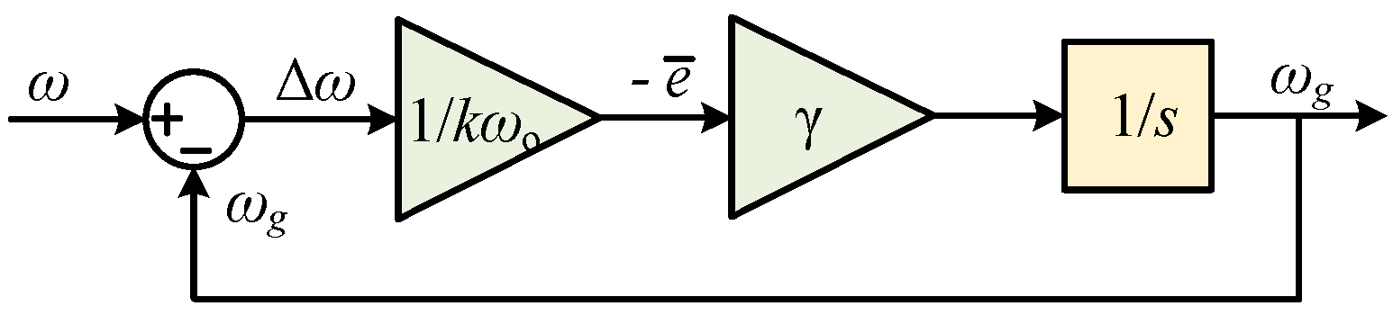
In the mentioned shipboard PV–diesel-battery power system, grid voltage stability is regulated by the exciter system of the diesel-engine synchronous generator. However, due to the large inertia of the diesel engine, grid voltage was in LF fluctuation on a large-scale time span. Due to the SPS with the slack bus, the fast response of the PV–battery inverter did not benefit system stability. For a good tradeoff between the speed of adaptive frequency and the stability of the power system, the rising time of the frequency system (shown in
Figure 4) was made greater than the time of the fundamental period. Hence, the error gain
γ was namely deduced from Equation (19) as
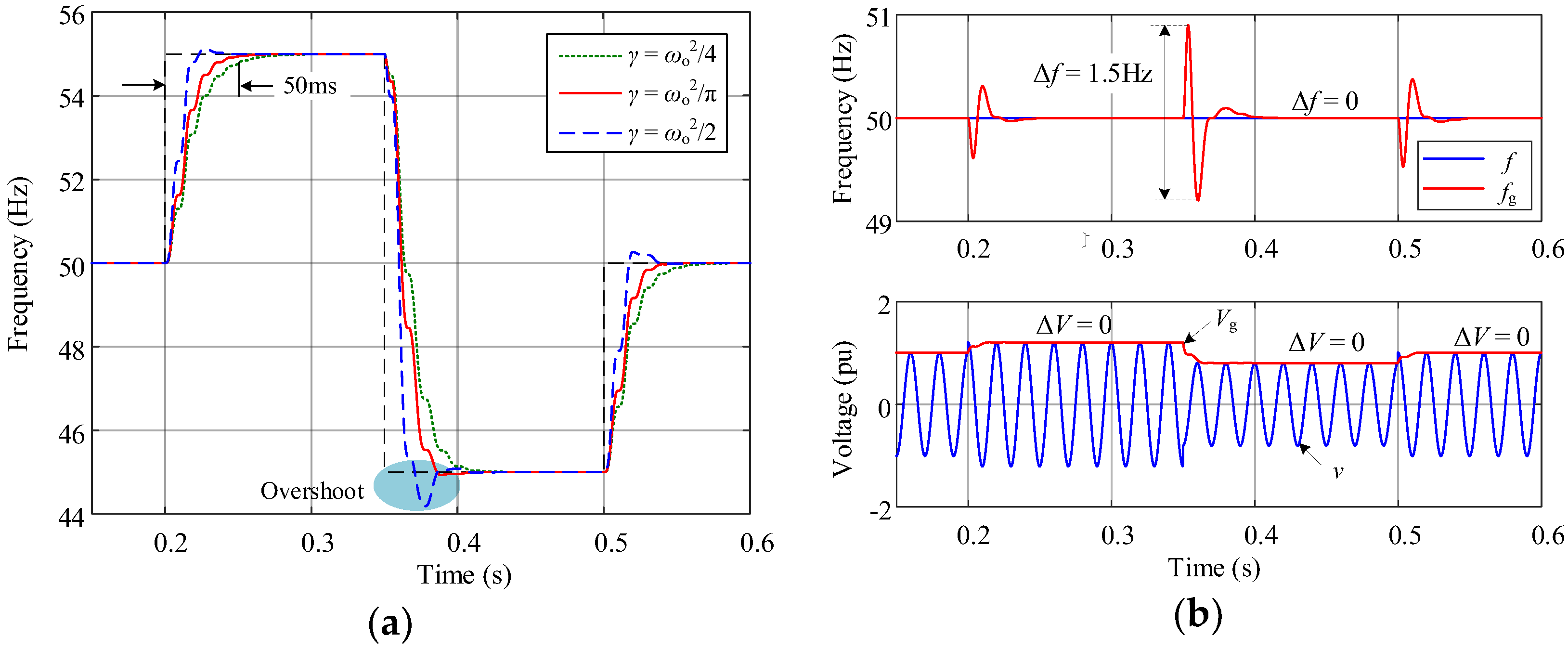
Figure 12 depicts the voltage/frequency dynamic response of SOGI-FLL when
k4 was equal to 1.414. When the grid frequency jumped from 50 to 55 Hz at 0.2 s, from 55 to 45 Hz at 0.35 s, and back to 50 Hz at 0.5 s;
γ was equal to
/2,
/
π, and
ωo2/4, respectively. The corresponding frequency dynamic response is shown in
Figure 12a, where
γ is the key parameter. Higher
γ brought about a short settling time with higher overshoot (see the curve of
γ = ωo2/4), whereas a lower
γ obtained good stability without overshoot, but had a longer settling time, as depicted in the curve of
γ = ωo2/2 with a 50 ms settling time. When
γ was
ωo2/
π, it showed good dynamic characteristics without overshoot and good stability. The optimal value of
γ is namely
Figure 12b shows the estimated amplitude and frequency transient response of SOGI-FLL when the input signal’s amplitude jumped from 1 to 1.2 per unit, or pu, at 0.2 s, from 1.2 to 0.8 pu at 0.35 s, and back to 1 pu at 0.5 s in
γ =
/
π. In this plot, we can see that
Vg was equal to
V, and
fg was constant regardless of whether
V changed or not, which means that
V cannot affect
Vg and
fg in steady states, which made the grid voltage
V and frequency
f have good consistency when the voltage/frequency was in swing. Moreover,
fg had a slight fluctuation of 1.5 Hz and less than 50 ms settling time, about two grid periods.
Vg could smoothly shift in one grid period without oscillation.


