Article

Thermal Performance of Microencapsulated Phase Change Material (mPCM) in Roof Modules during Daily Operation

1
Department of Civil Engineering, National Cheng Kung University, Tainan 701, Taiwan
2
Department of Architecture, National Cheng Kung University, Tainan 701, Taiwan
*
Author to whom correspondence should be addressed.
Energies 2018, 11(3), 679; https://doi.org/10.3390/en11030679
Submission received: 18 February 2018 / Revised: 13 March 2018 / Accepted: 15 March 2018 / Published: 17 March 2018
(This article belongs to the Section D: Energy Storage and Application)

Abstract

:
This study combines microencapsulated phase change materials (mPCMs) (core material: paraffin; melting points: 37 and 43 °C) and aluminum honeycomb boards (8 mm core cell) to form mPCM roof modules and investigates their heat absorption and release performances, as well as their impact on indoor heat gain by conducting experiments over a 24-h period, subject to representative weather. The outdoor boundary conditions of the module are hourly sunlight and nighttime natural cooling; on the indoor side of the module, the conditions are daytime air conditioning and nighttime natural cooling. The results indicate that compared to a roof module with a 43 °C melting point mPCM, the roof module with a 37 °C melting point mPCM had improved peak load-shifting capacity, but had a slightly increased indoor heat gain. The mPCMs in both roof modules were successfully cooled during the night, returning to their initial state, to begin a new thermal cycle the next day.

1. Introduction

A phase change material (PCM) is a substance with a high latent heat that can effectively store or release latent heat during its solid or liquid phase change (melting or solidifying). The PCM temperature can also be stably maintained during the latent heat transfer process. Therefore, in the application of energy storage and thermal environmental control, PCMs are a promising material choice. The applications of PCMs include PCM partition walls for regulating the temperature in a room, temperature control in space equipment to compensate for the enormous temperature difference between day and night, thermal management in electronic devices, batteries, or biochemical storage tanks, heat transfer enhancement by incorporating PCMs into the working fluid, and PCM thermal actuators.
Zhang et al. [1] showed that latent heat storage plays an important role in the heating and cooling of spaces; latent heat storage can reduce or shift the building electricity demand, thus achieving energy savings. This paper discusses the latent heat storage performance of PCMs, as well as introducing the physical properties of numerous PCMs and the latent heat storage results of different PCMs applied to various parts of a building. Kalnæs and Jelle [2] indicated that as a latent heat storage material, PCMs applied to buildings have already become a trend, and an increasing number of commercialized products have appeared. This paper reviews the most advanced PCMs on the market and selects a few of them to introduce, along with a discussion of their potential fields of application. There is an abundant literature related to the application of PCMs in building energy systems, which can be found in Memon [3], Konuklu et al. [4], Akeiber et al. [5], and Mohamed et al. [6].
Many papers have addressed the thermal characteristics of PCMs; however, for the applications of PCMs in building energy parameters, a thermal analysis of the PCM-containing building materials or the entire building should be considered. Silva et al. [7] experimentally studied PCM-containing blinds, and the experimental results indicated that PCM blinds have great potential in regulating the indoor thermal environment and improving energy utilization efficiency. Lecompte et al. [8] mixed micro-encapsulated PCM into concrete and mortar and studied its physical properties compared to ordinary concrete mortar. The results indicated that the micro-encapsulated PCM-mixed concrete mortar was able to maintain a certain degree of mechanical strength, but more importantly, it had better thermal performance than concrete and mortar alone. Zhou et al. [9] constructed a laminated composite PCM gypsum board and analyzed its thermal properties. The authors tested the thermal properties of 4-mm-thick PCM plasterboard in a naturally ventilated environment and obtained a maximum heat exchange of 15.6 W/m2 and a maximum heat storage of 363.7 W/m2. Additionally, they built a model house using the PCM gypsum board, and compared it to a model house built with ordinary gypsum board; the indoor temperature was reduced by as much as 5 °C with the PCM gypsum board.
Wang and Zhao [10] showed that the placement of windows is important for affecting solar heat gain; to reduce the heat transferred indoors through windows, this study experimented with PCM-containing windows. The results indicated that a thicker PCM layer furnished a greater reduction in solar heat gain. The melting point of PCMs is very important for reducing heat gain. When a 15-mm-thick PCM layer with a melting point of 29 °C was used in the hottest period of the summer in Shanghai, the maximum heat gain reduction reached 30%. Gracia et al. [11] analyzed the thermal performance of a ventilated facade with PCMs. Their research has a certain degree of complexity; thus, they proposed some numerical methods for simplification to better explain and describe the experimental process and results. Liu and Li [12] studied the thermal properties of solar chimneys with and without PCM. The PCM-containing solar chimney was divided into three groups: fully enclosed heating, semi-closed heating, and fully open heating. The experimental results indicated that in the heating stage, compared with the solar chimney without PCM, the PCM-containing solar chimney reduced the air flow; the opposite was true in the PCM heat release stage.
From the previous discussion, it is apparent that the methods of combining PCMs with building materials are diverse, and there are numerous related studies. However, PCMs may interact with construction materials and change their properties; in addition, leakage may be a problem over a long lifetime. However, micro-encapsulated PCMs (mPCMs) may change these circumstances, and they are becoming a very promising choice for employment in building materials. Lai et al. [13] integrated mPCM into gypsum to fabricate mPCM gypsum board and then investigated its physical properties and heat transfer behavior. Their research shows that cases with a higher Stefan number or sub-cooling have a higher heat transfer rate through the hot wall. Lai and Hokoi [14] constructed an mPCM honeycomb wallboard prototype. The results indicated that the aluminum honeycomb used for the main structure and heat transfer enhancement in the prototype swiftly transferred the heat flow into the mPCM. Thus, the time lag of the peak heating load was increased due to the PCM latent heat, effectively shifting the peak hours of energy use in the summer and accomplishing a lower surface temperature than others. Liu et al. [15] developed a wall tile containing macro-encapsulated PCM (macroPCM) and polyvinyl acetate (PVA). This tile showed a lower indoor heat flow than that of other tested construction materials and increased the time lag of the peak load, effectively shifting the peak energy demand in the summer.
By incorporating mPCMs into building construction, the through-wall/roof heat transfer can be appropriately controlled with the absorption and release of latent heat. This combination would result in an effective reduction in solar heat gain. Therefore, this study evaluates an mPCM roof module under typical temperature changes over a 24-h period and studies its heat absorption and release performance, as well as its impact on the indoor heat gain.

2. Research Methods

In this research, we construct a roof module with mPCM and aluminum honeycomb board and measure the heat absorption and release processes of the roof module during a one-day period. The tested module is placed on a wall opening of a climate chamber, one side of which is in contact with the airflow inside the air-conditioned chamber to simulate the indoor environment. A heating plate is attached to the other side of the module to simulate the solar heat gain experienced by the tested module through timing-controlled heating. Figure 1 shows the schematic diagram of the tested module and photos of the honeycomb boards with and without mPCM. The thermal performance of the tested module is analyzed by measuring the internal and surface temperatures of the tested module and the module surface heat fluxes.

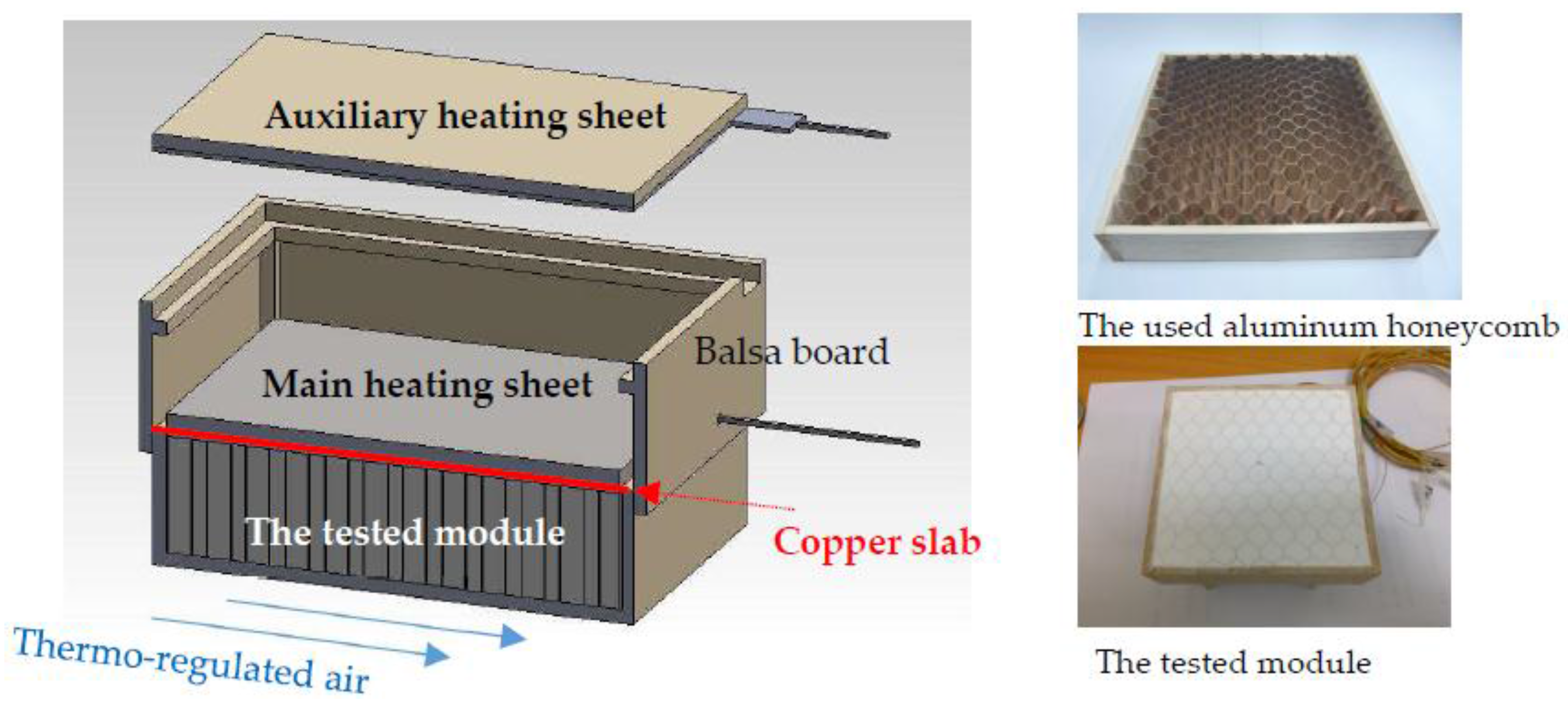
2.1. Tested Roof Module

To improve the low thermal conductivity of mPCMs and achieve the required stiffness, aluminum honeycomb (25.4-mm thick; 8 mm core cell) was used as a structural support skeleton, as well as as a thermal channel to enhance the heat transfer within the tested module. From the viewpoint of construction practices, the conventional roof thickness places restrictions on the test cell width W. Thus, the module dimensions were set to H 10 cm × W 2.54 cm × L 10 cm. mPCM powder was placed in a dehumidification box for 1 h to remove water attached to the power surfaces; then, it was poured and pressed into the experimental mPCM roof module. The weight of the mPCM used in both tested modules was 120.0 g. To reduce heat loss to the outside environment, the mPCM roof module was peripherally fabricated by Balsa boards with a board thickness of 2 mm, covered with natural cotton for thermal insulation and, then, placed into a wooden box.
A 10 × 10 cm mica heater, used as the main heating sheet (on the upper side of the module in Figure 1), was attached to a 1-mm-thick copper slab and the exterior side of the tested roof module to provide a time-changing heating flux. The electrical power output of the main heating sheet simulated representative weather, as described in Section 2.3. The copper slab was used to evenly distribute the heat from the main heating sheet and to offer the required heating flux conditions for the experiments.
An auxiliary heating sheet (a 10 × 10 cm mica heater) was placed 2 cm from the main heating sheet to reduce heat loss from the exterior side of the tested module to the outside environment. The heating power of the main heating sheet was controlled to enable the exterior side of the tested module to meet the set heating flux (Figure 2). The heating power of the auxiliary heating sheet was controlled manually to let the surface temperature (Taux) of the auxiliary heating sheet meet the surface temperature (Tmain) of the main heating sheet. This configuration could ensure that heat flow from the main heating sheet was conducted inwards to the investigated module.
The interior side (on the bottom side in Figure 1) of the tested module was composed of a wooden plate. An air conditioner, located on the interior side of the tested module, was used to offer the thermo-regulated air, flowing over this interior side with a set temperature (Ti) and airflow velocity (Vi).
Five type K thermocouples were positioned on the surface of the main heating sheet and auxiliary heating sheet to obtain Tmain and Taux, respectively. Five thermocouples were placed on the outside surfaces of the heat flux sensors and the wooden wall (the module’s interior side). Finally, five thermocouples were placed 0.5 cm apart inside the mPCM to observe the temperature distribution during the experiment. Heat flows outward from the exterior and lateral sides of the module and inward to the indoor side were measured directly by heat flux sensors. The measurement apparatuses included AC/DC power supply units (Gwinstek APS-1102, Good Will Instrument Co., Ltd., New Taipei City, Taiwan), heat flux sensors (MF-180, EKO Instruments, Tokyo, Japan), data acquisition units (MX-100, YOKOGAWA, Tokyo, Japan), and a PC.

2.2. The mPCM Capsule

The mPCMs used in this paper were fabricated by Microtek Laboratories Inc. (Dayton, OH, USA). The properties of the mPCM with the melting point of 37 °C are as follows: the model name is MPCM 37-D, the core material is paraffin, the mean particle size is 17–20 microns, the capsule composition is 85–90 wt. % PCM and 10–15 wt. % polymer shell, the specific gravity is 0.9, and the heat of fusion is 166.54 kJ/kg [14]. Before and after mPCM melting, the average specific heat values were 3.21 and 2.70 kJ/(kg·°C), respectively [14]. The properties of the mPCM with the melting point of 43 °C are as follows: the model name is MPCM 43-D, the core material is paraffin, the mean particle size is 14–24 microns, the capsule composition is 85–90 wt. % PCM and 10–15 wt. % polymer shell, the specific gravity is 0.9, and the heat of fusion is 134.0 J/g. Before and after mPCM melting, the average specific heat values were 3.45 and 2.35 kJ/(kg·°C), respectively.

2.3. Experimental Procedure

The time variation of the heating flux on the exterior side of the module ( q h ) and the mPCM used in the modules (37 °C and 43 °C melting points) were the main control parameters. This time- variant heating flux on the exterior side, under the control of power from the power supply unit, simulated the typical solar heat gain on a roof in a tropical region (Tainan City) in Taiwan. The convective condition of the interior side of the module was achieved by the constant airflow temperature (Ti = 26 °C) and speed (0.5 m/s) supplied by an air conditioner, simulating the typical indoor air environment near the roof. The initial temperature of the entire module was the same as that of the interior side (26 °C) in the experiment.
To reproduce solar heat gain conditions that were as realistic as possible, the time-variant heat flux q h at the exterior side was gotten from meteorological data measured from June to August 2015 (the summer season in Taiwan) for the average hourly amount of solar heat gain and was considered to be a sine function of time, as shown in Equation (1) and Figure 2. Figure 2 illustrates the measured meteorological data and heating flux input, normalized by their respective peak values. The amount of solar heat gain immediately before sunrise and immediately after sunset were both zero. Immediately after sunrise, the solar heat gain begins to increase until a maximum ( G s , o ) is reached, after which the solar heat gain decreases until sunset:
q h ( t ) = G s , o sin ( π t T ) ,   0 t T , T = 10   h
where G s , o is the peak value (200, 400, and 600 W/m2) of the heating power in the experiments.
The temperature inside the air-conditioned climate chamber was allowed to reach a stable initial value of Ti before the experiment, and then all instruments were started. During the experimental process, the temperature setting of the auxiliary heating sheet was adjusted every 2–10 min. After 10 h of heating, the heating power units and air conditioners were shut off, and the cotton insulation was removed to allow the tested module to cool naturally for 14 h. The experiments for each module/test were repeated three times to confirm repeatability.

2.4. Experimental Uncertainty

Uncertainties in the measured quantities for this study were estimated to be ±0.1 °C for the temperature, ±0.05 W for the heating power input measured by an electronic watt meter, and ±2% for the heating flux measured by the heat flow meter. The indoor heat flux and heat fluxes outward the peripheries of the module were measured simultaneously. To reproduce the thermal behavior of the roof modules during service and to reduce the peripheral heat loss of the tested module, thermal insulation material was applied around the lateral sides of the tested modules. From the heat flow measurement within the peripheral insulation, the average accumulated heat loss with Gs,o = 600 W/m2, Ti = 26 °C, and Vi = 0.5 m/s was 2.73% of the total heating input. All the heat losses were within acceptable levels. These errors are believed to be inconsequential to the results of the experiment.

3. Results and Discussion

The experiment is divided into two stages: 10 h of solar heating during the daytime and 14 h of natural convection cooling at night. The heating power at the exterior (outdoor) side of the tested roof module was automatically controlled (see Section 2.3, Experimental Procedure) to simulate the daily solar heat gain. The heating power peaks of the sine function of time at the exterior side of the module were set as 200, 400, and 600 W/m2. During the daytime, the convective condition of the interior (indoor) side was set as Ti = 26 °C and Vi = 0.5 m/s. During the nighttime, the convective condition of the interior side was also set as Ti = 26 °C, and the wind speed was close to 0 m/s (no wind outdoors). The melting temperatures, Tm, of the mPCMs used in the modules were 37 °C and 43 °C, and these were used to determine the location of the melting interface.

3.1. Case Studies

Figure 3 and Figure 4 show the hourly change in temperature and the heat flux of the mPCM roof module (with a 37 °C melting point) under peak heating power conditions of 200 and 600 W/m2. Because heating power (denoted by the symbol ◯ in Figure 3 and Figure 4) simulates the solar heat gain, the hourly change in the temperature and the heat flux also shows a sinusoidal-like form within 600 min (10 h) of the experiment (simulating daytime sunshine). Because the indoor side of this experiment simulates an air-conditioned space, to realistically reflect the small sawtooth-shaped amplitude variation of the air temperature in an air-conditioned space resulting from the on-off operation mode of an actual air conditioner compressor, the figures in the results are presented in raw form, without averaging, but the description of the data is mainly presented with averaged values.
Figure 3a shows the temperature distribution of the 37 °C melting point module for the condition of a peak heating power of 200 W/m2. The building roof receives heat irradiation from the sun during the daytime, and the outdoor side of the mPCM roof module responds to absorbing solar heat gain. Thermal energy enters the mPCM in the module through heat conduction. At the beginning of the experiment, the temperature at various parts of the module gradually increased. However, the temperature of the mPCM remained below the PCM melting point during the entire heating process; therefore, the phase change phenomenon did not occur, and the PCM entirely absorbed sensible heat. As a structural support, as well as a heat conduction path, the aluminum honeycomb was able to rapidly conduct solar heat gain into the mPCM, increasing the module temperature slowly and uniformly, such that a thermal stratification phenomenon was not observed. At 510 min, the temperature of the indoor side of the module (denoted by the symbol + in Figure 3a) reached a maximum value of 32.6 °C, and the time lag was 210 min. Although the temperature change was not large, the time lag phenomenon was significant.
Figure 3b shows the hourly heat flux change for the condition of a peak heating power of 200 W/m2. At the beginning of the daytime solar heating, because the heating power was low, the temperature variation of the entire roof module was small; therefore, the heat dissipating from the indoor side of the module was low. Due to the effect of the auxiliary heating sheet, the outdoor heat loss from the module was controlled to be close to zero. As the heating time increased, the module temperature began to increase gradually, and the indoor heat flow through the module began to increase gradually. The average heat flux onto the indoor side (denoted by the symbol x in Figure 3b) had a maximum value of approximately 46.0 W/m2 at 515 min. The stored heat flux (denoted by the symbol in Figure 3b) had a maximum value of 166.7 W/m2 at 300 min. Compared with the heating power, there was almost no time lag. After approximately 9.5 h of daytime heating, the module’s internal heat storage became negative, indicating that the module’s heat gain was already less than its heat loss at this time.
In the nighttime cooling stage, the heating plate power was turned off to simulate the lack of sunshine, which caused the heat flux to the outdoors through the tested module (denoted by the symbol in Figure 3b) to increase to a certain value, remain constant for a certain time (approximately 3 h), and then decrease slowly. Meanwhile, the module’s outdoor surface temperature (denoted by the symbol Energies 11 00679 i001 
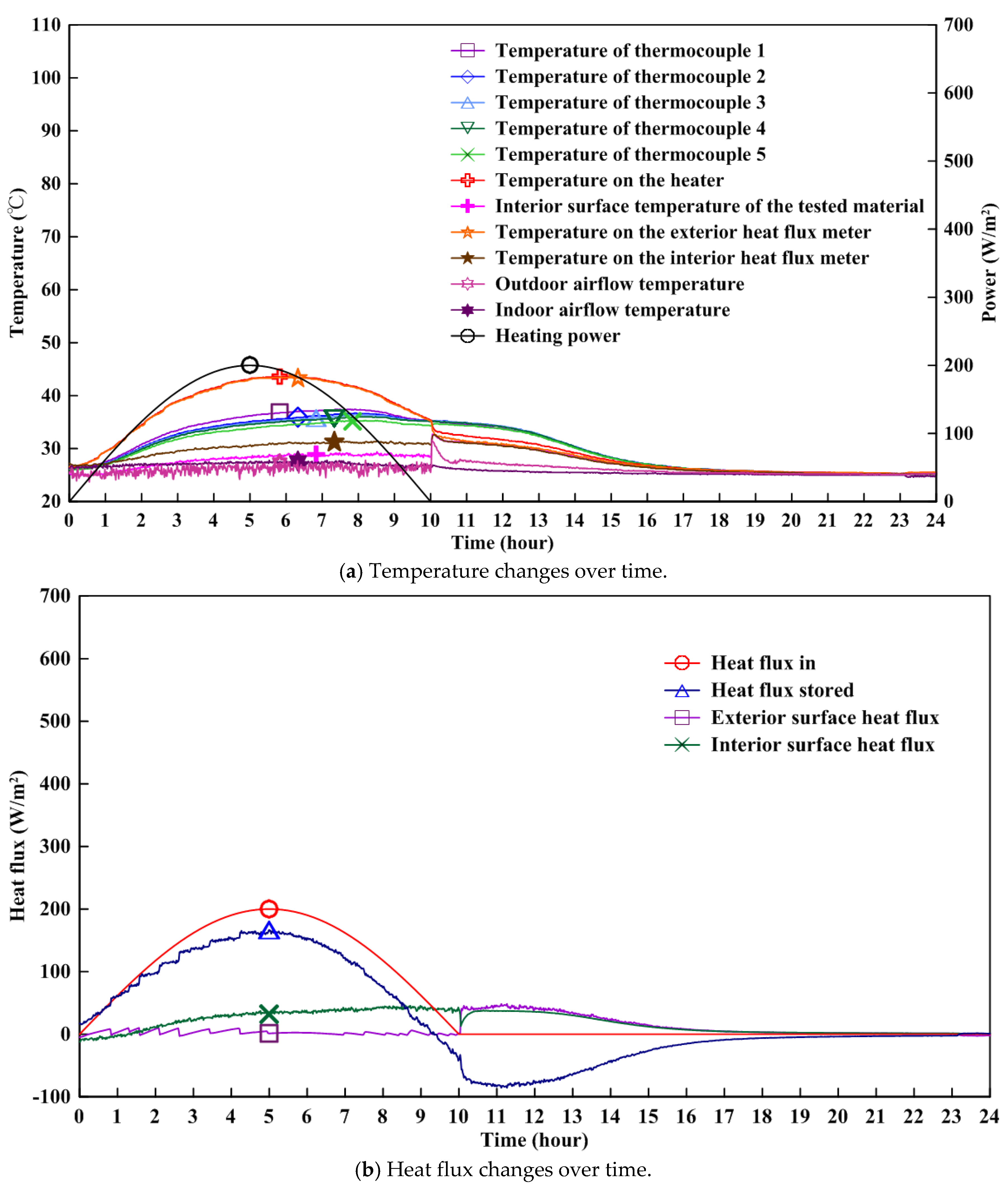
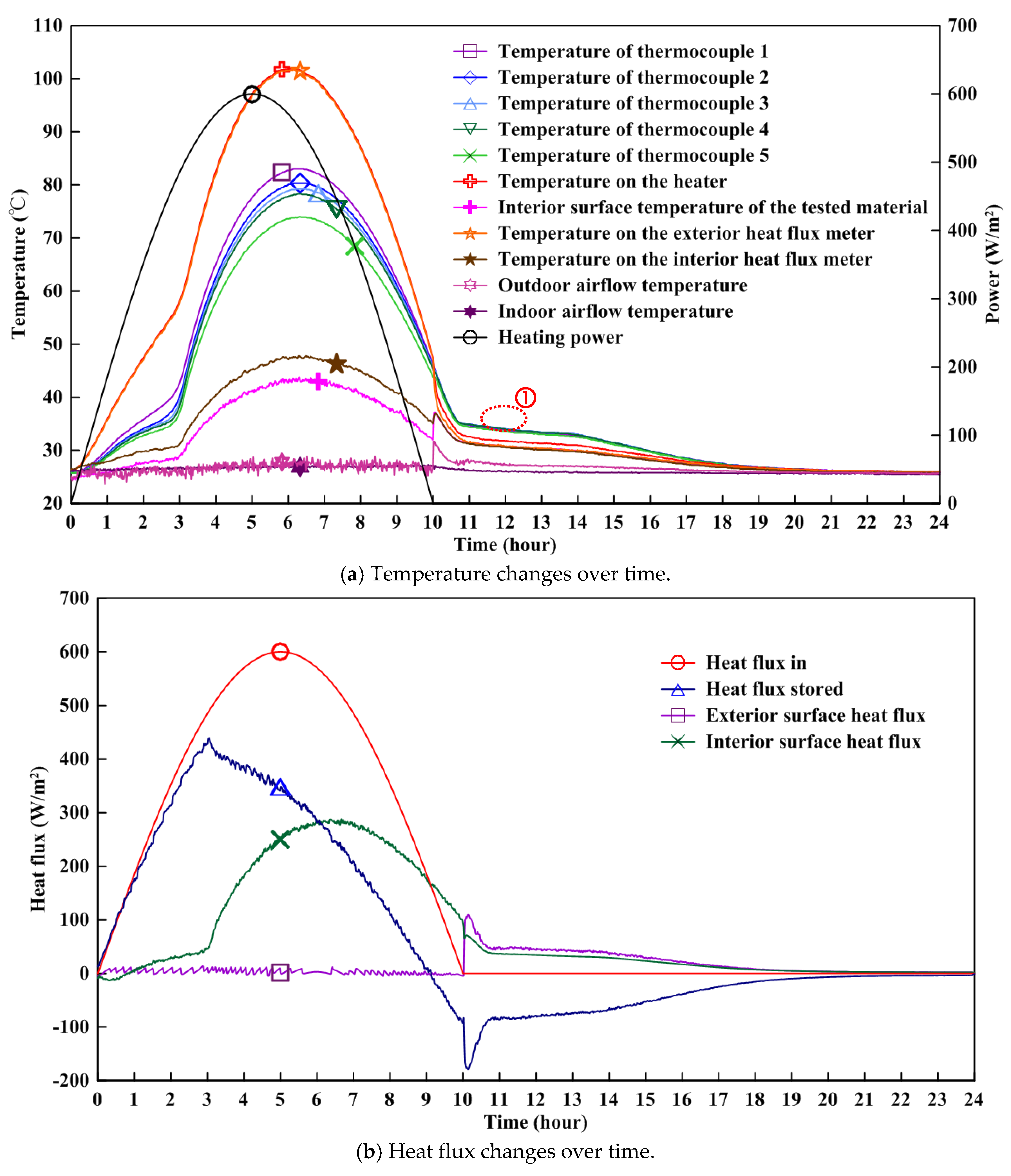
in Figure 3a) continuously decreased. The indoor air-conditioning was turned off in the experiment to reflect a lack of air-conditioning in the off-work hours, which caused the module’s indoor side surface temperature (denoted by the symbol + in Figure 3a) to increase slightly at the beginning and then slowly decrease. The indoor heat flux through the module (denoted by the symbol x in Figure 3a) decreased slightly, followed by a rapid increase, and then a slow decrease again. In the early stages of nighttime cooling, due to the above boundary condition change, both the temperature and the heat flux values underwent large changes and entered the smooth natural cooling stage after approximately 30 min (when the experiment time was 10.5 h). The temperature and heat flux at all points decreased gradually. At roughly the sixth hour of nighttime cooling (when the experiment time reached 16 h and the actual time was approximately 23:00), the temperature and heat flux at all points recovered to their initial states.
Figure 4 shows the experimental results for when the peak heating power was 600 W/m2. From Figure 4a, during the period of 0.5 to 2 h of the experiment, the module internal temperature (figure legend “thermocouple 1–5” in Figure 4a) increased rapidly from 26 °C to approximately 35 °C. The mPCM interior was still in its solid state during this stage, and it was absorbing heat in the form of sensible heat. From 2 to 3 h, the module interior temperature was stable, maintaining at approximately 37 °C. At this stage, the interior of the mPCM gradually changed from a solid to a liquid and absorbed solar heat gain in the form of latent heat. From 3 to 10 h, the module’s interior temperature variation showed a sine wave shape, along with the solar heating mode, which increased from 37 °C to a peak value of 77 °C and then decreased back to 37 °C. The interior of the mPCM was liquid and absorbed heat in the form of sensible heat. The temperature change exhibited a significant time lag and amplitude reduction. The temperature time lag, defined as the difference in time between when the peak temperature of the interior side (denoted by the symbol + in Figure 4a occurs and when the peak heating (denoted by the symbol ◯ in Figure 4a occurs, is 78 min. The temperature decrement factor, defined as the ratio of the amplitude of the highest temperature of the interior side to that of the heated surface (denoted by the symbol Energies 11 00679 i001 in Figure 4a, is 0.43.
During the nighttime, the roof module starts to release the heat energy that was stored during the daytime. From 10.7 to 14 h, the module’s interior temperature at each measuring point showed slight differences (denoted by the symbol ① in Figure 4a), maintaining at approximately 35 °C. The mPCM interior started to solidify at this stage, gradually changing from liquid to solid, and released heat in the form of latent heat. Thus, the temperature needed for solidifying mPCMs was slightly lower than the melting point, showing its supercooling effect. From 14 to 20 h, the module’s interior temperature rapidly decreased from 33 °C. From 20 to 24 h, the module interior temperature only slightly changed, maintaining at approximately 26 °C. There were still a few thermal stratifications inside the mPCMs, but during the nighttime cooling, the module’s interior temperature showed a consistent variation behavior, demonstrating no thermal stratification.
Figure 4b shows the heat flows for a peak heating power of 600 W/m2. The solar heat gain (denoted by the symbol ◯ in Figure 4b) peak value appeared at the experimental time of 300 min. The heat flux into the indoor side (denoted by the symbol x in Figure 4b) started to greatly increase at 3.3 h, which roughly corresponds to the time the mPCM interior completely melted (this phenomenon can also be seen from the temperature variation in Figure 4a). At this time, the latent heat of the PCM was exhausted, and as the solar heat gain continued, the mPCM interior temperature and the heat flow into the indoor side also increased rapidly. A maximum value of 288.2 W/m2 of heat flow into the indoor side appeared at 400 min, while the maximum stored heat flux of 439.8 W/m2 occurred at 183 min.

3.2. Findings

Table 1 shows the temperature time lag and temperature decrement factor of each experiment during the daytime. It is evident that when using a certain material, as the heating power increases, the temperature time lag and the temperature decrement factor both decrease. At a high heating power, the temperature time lag and temperature decrement factor of the 37 °C mPCM performed better than that of the 43 °C mPCM and featured a better thermal performance.
Figure 5 shows the time lag and decrement factor of heat flux of the tested module filled with 37 °C and 43 °C mPCMs for different peak heating power conditions. The heat flux time lag is the difference in time between when the peak interior surface heat flux occurs and peak solar heat gain occurs. A larger time lag indicates a better heat storage and/or insulation performance and can shift the daily peak load more effectively. The heat flux decrement factor is the ratio of the peak interior surface heat flux to the peak solar heat gain. A lower decrement factor indicates better heat storage and/or thermal insulation performance, which can reduce peak indoor heat gain.
It can be seen from Figure 5 that for the same type of PCM, as the peak heating power increases, the time lag of the heat flux decreases, which reduces the peak load shifting capability of the tested module. Nonetheless, the time lag at the high heating power peak (600 W/m2) of the 37 °C melting point module was only slightly lower than that at 400 W/m2, and the difference was minimal.
When the heating power peak of the 37 °C melting point module was increased from 400 W/m2 to 600 W/m2, the time lag was slightly reduced, but the decrement factor was maintained at 0.45–0.47, showing its good heat flux impedance ability. For high heating power conditions, the decrement factor of the 43 °C melting point module was lower than that of the 37 °C melting point module, indicating that the 43 °C melting point module has a relatively low indoor heat gain. However, the time lag of the 43 °C melting point module was much lower than that of the 37 °C melting point module.

4. Conclusions

This research combines mPCMs (core material: paraffin; melting temperatures: 37 and 43 °C) and aluminum honeycomb boards (8 mm core cell) to form mPCM roof modules. The thermal cycling characteristics of the modules are studied by measuring their heat flux and temperature variation. During the first 10 h of the experiment, the heating power of the module’s outdoor surface simulates hourly sunshine changes, and an air conditioning system (set to 26 °C) is applied to maintain the interior side environment of the module. During the experiment time between 10 and 24 h, nighttime conditions are simulated, and the module’s indoor and outdoor sides are subject to natural convection cooling. The following conclusions can be drawn from the results:
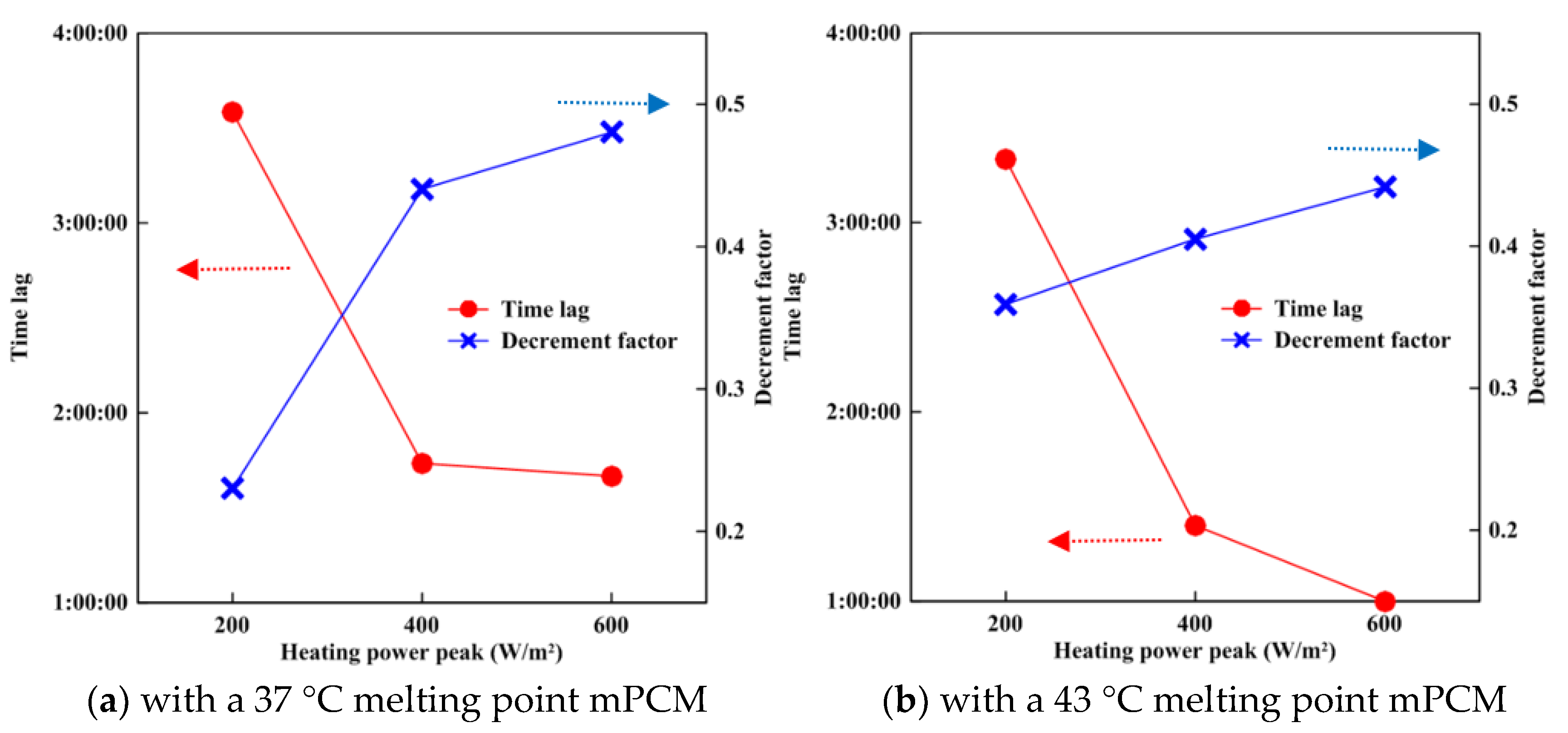
  • When the tested mPCM roof modules were at a high solar heat gain (600 W/m2), the decrement factor of the heat flux of the 37 °C melting point module was 0.48, which was slightly higher than the value of 0.44 for the 43 °C melting point module, indicating that the 37 °C melting point module has a higher peak indoor heat gain (approximately 4% higher). However, the time lag of the heat flux of the 37 °C melting point module was 100 min, which was far greater than the 60 min of the 43 °C melting point module, indicating that the 37 °C melting point module has the better peak load shifting ability.
  • For the conditions of daytime heating and nighttime natural convection cooling established in this study, the mPCMs with 37 and 43 °C melting points inside the two roof modules are both effective at releasing their solar heat, allowing them to be restored to their initial state to begin thermal cycling again the following day.
The results are limited to the used mPCM and the specific chosen location. To explore the practical aspects and applications at other locations, mPCMs with different melting points should be tested.

Acknowledgments

Support from the Ministry of Sciences and Technologies (MOST) of ROC in Taiwan through grant no. MOST 105-2923-E-006-006-MY3 in this study is gratefully acknowledged.

Author Contributions

Qi Zhou and Chi-Ming Lai conceived and designed the investigated model; Qi Zhou performed the experiments; Qi Zhou, Pin-Feng Liu and Chun-Ta Tzeng analyzed the data; and Pin-Feng and Chi-Ming Lai wrote the paper.

Conflicts of Interest

The authors declare no conflict of interest.

References

  1. Zhang, Y.; Zhou, G.; Lin, K.; Zhang, Q.; Di, H. Application of latent heat thermal energy storage in buildings: State-of-the-art and outlook. Build. Environ. 2007, 42, 2197–2209. [Google Scholar] [CrossRef]
  2. Kalnæs, S.E.; Jelle, B.P. Phase change materials and products for building applications: A state-of-the-art review and future research opportunities. Energy Build. 2015, 94, 150–176. [Google Scholar] [CrossRef]
  3. Memon, S.A. Phase change materials integrated in building walls: A state of the art review. Renew. Sustain. Energy Rev. 2014, 31, 870–906. [Google Scholar] [CrossRef]
  4. Konuklu, Y.; Ostry, M.; Paksoy, H.O.; Charvat, P. Review on using microencapsulated phase change materials (PCM) in building applications. Energy Build. 2015, 106, 134–155. [Google Scholar] [CrossRef]
  5. Akeiber, H.; Nejat, P.; Majid, M.Z.A.; Wahid, M.A.; Jomehzadeh, F.; Famileh, Z.I.; Calautit, J.K.; Hughes, B.R.; Zaki, S.A. A review on phase change material (PCM) for sustainable passive cooling in building envelopes. Renew. Sustain. Energy Rev. 2016, 60, 1470–1497. [Google Scholar] [CrossRef]
  6. Mohamed, S.A.; Al-Sulaiman, F.A.; Ibrahim, N.I.; Zahir, M.H.; Al-Ahmed, A.; Saidur, R.; Yılbaş, B.S.; Sahin, A.Z. A review on current status and challenges of inorganic phase change materials for thermal energy storage systems. Renew. Sustain. Energy Rev. 2017, 70, 1072–1089. [Google Scholar] [CrossRef]
  7. Silva, T.; Vicente, R.; Rodrigues, F.; Samagaio, A.; Cardoso, C. Development of a window shutter with phase change materials: Full scale outdoor experimental approach. Energy Build. 2015, 88, 110–121. [Google Scholar] [CrossRef]
  8. Lecompte, T.; Le Bideau, P.; Glouannec, P.; Nortershauser, D.; Le Masson, S. Mechanical and thermo-physical behaviour of concretes and mortars containing phase change material. Energy Build. 2015, 94, 52–60. [Google Scholar] [CrossRef]
  9. Zhou, T.; Darkwa, J.; Kokogiannakis, G. Thermal evaluation of laminated composite phase change material gypsum board under dynamic conditions. Renew. Energy 2015, 78, 448–456. [Google Scholar] [CrossRef]
  10. Wang, Q.; Zhao, C.Y. Parametric investigations of using a PCM curtain for energy efficient buildings. Energy Build. 2015, 94, 33–42. [Google Scholar] [CrossRef]
  11. Gracia, A.; Castell, A.; Fernández, C.; Cabeza, L.F. A simple model to predict the thermal performance of a ventilated facade with phase change materials. Energy Build. 2015, 93, 137–142. [Google Scholar] [CrossRef]
  12. Liu, S.; Li, Y. An experimental study on the thermal performance of a solar chimney without and with PCM. Renew. Energy 2015, 81, 338–346. [Google Scholar] [CrossRef]
  13. Lai, C.-M.; Chen, R.H.; Lin, C.-Y. Heat transfer and thermal storage behaviour of gypsum boards incorporating micro-encapsulated PCM. Energy Build. 2010, 42, 1259–1266. [Google Scholar] [CrossRef]
  14. Lai, C.-M.; Hokoi, S. Thermal performance of an aluminum honeycomb wallboard incorporating microencapsulated PCM. Energy Build. 2014, 73, 37–47. [Google Scholar] [CrossRef]
  15. Liu, P.-F.; Lin, Y.-P.; Tzeng, C.-T.; Lai, C.-M. Heat transfer and energy performance of a PVA wall tile containing macro-encapsulated PCM. Energies 2016, 9, 652. [Google Scholar] [CrossRef]
Figure 1. Test cell experimental setup (left) and the tested mPCM roof module (right).
Energies 11 00679 g001
Figure 2. Normalized heating flux input and measured meteorological data.
Energies 11 00679 g002
Figure 3. Heat transfer behavior of the tested module (Tm = 37 °C, Gs,o = 200 W/m2).
Energies 11 00679 g003
Figure 4. Heat transfer behavior of the tested module (Tm = 37 °C, Gs,o = 600 W/m2).
Energies 11 00679 g004
Figure 5. Relationship between the heating power peak and the time lag of the heat flux and decrement factor of the heat flux.
Energies 11 00679 g005
Table 1. Temperature time lag and temperature decrement factor of each experimental during the daytime.
Used PCMCharacteristics200 W/m2400 W/m2600 W/m2
37 °C mPCMTemperature time lag303 min95 min78 min
Temperature decrement factor0.750.500.43
43 °C mPCMTemperature time lag304 min53 min53 min
Temperature decrement factor0.680.520.46

