An Efficient Stator Inter-Turn Fault Diagnosis Tool for Induction Motors


Department of Electrical Engineering, King Fahd University of Petroleum and Minerals, Dhahran 31261, Saudi Arabia
*
Author to whom correspondence should be addressed.
Energies 2018, 11(3), 653; https://doi.org/10.3390/en11030653
Submission received: 22 February 2018
/
Revised: 9 March 2018
/
Accepted: 12 March 2018
/
Published: 14 March 2018
(This article belongs to the Section I: Energy Fundamentals and Conversion)
Abstract
:Induction motors constitute the largest proportion of motors in industry. This type of motor experiences different types of failures, such as broken bars, eccentricity, and inter-turn failure. Stator winding faults account for approximately 36% of these failures. As such, condition monitoring is used to protect motors from sudden breakdowns. This paper proposes the use of neural networks as an efficient diagnostic tool for estimating the percentage of stator winding shorted turns in three-phase induction motors. A MATLAB-based model was developed and simulated under different fault-load combination cases for different sizes of motors. The motor’s developed electromechanical torque was selected as a fault indicator. For the design and training of the neural network, the mean, variance, max, min, and F120 time based on statistical and frequency-related features were found to be very distinct for correlating the captured electromechanical torque with its corresponding percentage of shorted turns. In the training phase of the neural network, five different motors were used and are referred to as seen motors. On the other hand, for testing the efficiency of the developed diagnostic tool, the electromechanical torque under different fault-load combination cases, previously never seen from the first five motors and those of two new motors (referred to as unseen), was used. Testing results revealed accuracy in the range of 88–99%.
1. Introduction
Motors are extensively used in many industrial applications, such as manufacturing plants, for power generation in the gas and oil industries, as well as for refining and milling. Induction motors are the most popular type of rotating machines that are used in industry and hence, they are known as the industry workhorse [1]. Due to continuous and harsh operating conditions of electric motors, they are subjected to several types of faults and subsequent failure that could affect their normal operation. However, in the industry, the normal and reliable operation of electric motors is essential. If any failure occurs, it may result in a loss of revenue, reduced output, emergency maintenance costs and resulting in out-of-service problems (a lengthy service outage). Therefore, early recognition of abnormalities in a motor may help to avoid expensive breakdowns. Thus, condition monitoring and fault diagnostics play a key role in the proper operation of rotating electrical machines [2,3].
In practical applications, electrical motors can experience different types of faults. In general, electrical motor failures can be categorized into electrical and mechanical faults [4]. Electrical faults/asymmetries can be further categorized into rotor and stator faults. Rotor faults include broken rotor bars, rotor eccentricity, breakage of end-rings, rotor bow, and demagnetizing of permanent magnets [5,6,7]. Stator faults include stator windings defects, stator core defects, and stator frame defects [8]. Mechanical faults include bearing damage and shaft defects [9]. Literature has reported that stator winding faults are one of the common faults in an electric machine, with approximately 36% of faults in an induction machine due to stator winding faults [8]. The stator describes the external group of coils, which apply the electromagnetic force to the rotor and cause it to rotate. The main parts of the stator are the core, windings, and the frame. These parts are subjected to unavoidable stress, whether this is mechanical or electrical. These stresses severely affect the condition of the stator, leading to faults. These faults are known as phase-to-ground faults, phase-to-phase faults, stator inter-turns faults, and coil to coil faults, which also includes an open circuit in one phase, and core damage [10,11,12].
Large numbers of electrical drives are installed in an industrial plant. Thus, monitoring the health of individual motors is crucial in such an establishment. Early fault diagnostics is extremely important for avoiding the catastrophic effects of sudden failure of electric drive systems. Therefore, an accurate modelling of motors is the first step in the recognition of motor abnormalities [13]. Based on the literature, two approaches are used for modeling motors under faults, which are the analytical (electrical or magnetic) and finite element approaches [8,14]. In the literature, different types of signals have been used as an indicator for motor fault diagnosis. These indicators include magnetic flux, vibration, stator current (negative and zero sequence or third harmonic component), zero sequence component of voltage, thermal image processing, instantaneous real power and reactive power, phase shift between stator and supply voltages, and acoustic noise [9,11,15,16,17,18,19,20,21,22,23,24,25,26,27,28]. Moreover, many researchers used the instantaneous torque as a fault indicator in induction motors [18,21,29,30,31]. It is important to mention that there are differences in the instantaneous torque response under broken bar and inter-turn faults [30]. In addition, based on previous studies [18,21], the time response of torque at the steady state is different under these two types of faults, while the prominent frequency components during faults are also different. These differences will help in discriminating between the two types of faults.
Preventive maintenance is always desired compared to corrective maintenance. Huge research efforts have been undertaken worldwide to develop incipient fault (before the actual occurrence of faults) diagnostic techniques. Neural network (NN) or known as artificial neural network (ANN) is a tool that plays an important role in developing online and offline diagnostic tools for motors, generators, transmission lines, cables, and transformers [32,33,34,35,36,37]. A mathematical model of an induction machine with stator inter-turn fault has been derived based on winding function theory [8]. The developed model showed that having inter-turn faults will introduce asymmetry in stator three phase currents (negative and zero sequence components increases with an increase in shorted turns number). In addition, pulsating torque at double supply frequency was also introduced. Accordingly, the consequences of faults can help in detecting the severity of inter-turn faults. Similar to reference [38], a mathematical model of an induction motor with stator inter-turn fault has been used for detecting faults, while the motor is running. The stator current was used for detecting such faults based on the magnitude of particular frequency components in its spectrum. Both experimental and simulation analysis were conducted with around 8% of the phase turns being shorted. They found that no new frequency components are introduced in the stator current due to the occurrence of faults, although a rise in some frequency components already existing in the healthy motor current spectrum were recorded.
A novel technique has been developed for online detection of stator inter-turns faults in the induction machine using infrared images [16]. Hence, the magnitude of the current in the faulty part of the stator winding was significantly higher than the rated current of the machine. This current generates excessive heat, which is perceived by an infrared camera as a hot spot on the motor surface. The developed method is based on extracting several types of features from the captured infrared images, histogram-based features, and structure-based features, which help in detecting the severity and the location of inter-turn faults. Both experimental and simulation analysis were conducted, with around 40% of the turns of one phase being shorted. Results showed that the developed method was effective in detecting such faults. A fuzzy logic system has been implemented for detecting the status of having stator inter-turn faults in the induction machine [39]. The implemented system used the magnitude of the input current for detecting faults. The used data in the construction of the system are collected by simulating the finite element model of the motor under different loading and shorted turns conditions. Identifying the unbalance supply as inter-turn faults is a possible drawback of the implemented system.
For detecting the location of inter-turn stator faults in induction motors, a tool was developed using feedforward neural networks [40]. The developed neural network has three inputs and three outputs. The inputs are the phase shifts between the line currents and phase voltages of the machine, while each output represents the status of one stator phase (healthy or faulty). Two sets of data, simulated and experimental, were used for developing two different neural networks. These data were collected under different loading and number of shorted turns (up to 12.5%) conditions. The experimentally developed neural network was tested using unseen motors, with the results found to be acceptable. However, the effect of having an unbalanced supply voltage fault has not been considered. In reference [41], the designed neural network for discriminating between inter-turn faults and unbalanced supply voltage faults has three inputs and four outputs. The inputs are the phase shifts between line currents and phase voltages of the machine, while the first three outputs represent the status of the stator phases (healthy or faulty) and the fourth output represents the status of unbalanced supply voltages. The data for training and testing neural networks have been acquired under different loading, number of shorted turns (up to 20%), and unbalance supply conditions. The performance of the NN was found to be accurate for fault diagnosis. However, the phase shifts between the line currents and phase voltages are very sensitive in detecting unbalance in supply voltages. Thus, we should consider that serious confusion could result from using the phase shift as an indicator for inter-turn faults [17]. However, to overcome this confusion, an NN with one extra input (the magnitude of the negative sequence component of the voltage) compared with the previously reported one was designed [17]. The data used for training and testing the designed neural network were generated by simulating the mathematical model with different loading, numbers of shorted turns, and unbalance voltage sources. The validation of the proposed scheme experimentally confirmed the accuracy and efficiency of the method.
Two neural network topologies, which are namely the multilayer perceptron ANN and radial basis function ANN, have been designed for detecting stator inter-turn faults under unbalanced supply voltages and different loading conditions [42]. The inputs to the neural networks are the mutual information between motor input phase currents, while the output is the status of having stator faults. Results showed that the accuracy of the implemented system was 93–99%. In reference [15], both instantaneous active and reactive power spectrum were found to be good indicators for detecting stator inter-turn faults and for discriminating between the faults and unbalanced supply. Moreover, the magnitude of the 2f component of the power and reactive power spectrum is directly proportional to the severity of the stator inter-turn faults [15]. The optimal multilayer perceptron neural network has been designed for detecting two types of fault in an induction machine (stator inter-turn faults and dynamic eccentricity faults) [43]. The inputs of the designed neural network are the set of statistical features (skewness, kurtosis, standard deviation, etc.). The statistical features are extracted using the input current of the machine. There are four inputs, including: the status of healthy motor, the status of inter-turn fault, the status of dynamic eccentricity fault, and finally the status of having both faults. The final result of the designed neural network showed good accuracy. In another study [44], a cascaded radial basis functional NN for detecting stator inter-turn faults and dynamic eccentricity fault in an induction machine was implemented. An unsupervised NN has been proposed for detecting the location of stator faults in an induction machine [45]. Clark transformation components of the stator current are the inputs to the proposed network, while the output is the faulty location.
Based on the above literature, most previous research work for stator inter-turn fault diagnostics focused on detecting the occurrence of faults, their location and severity for one specific used and seen motor. Testing of the accuracy of the diagnostic tool was conducted on this used and seen motor. No work has been reported in developing a tool that is capable of detecting the percentage of stator inter-turn faults for motors with a wide range of ratings (hp) and parameters. In addition, no single tool has been able to diagnose the possibility of a failure on a motor never seen before. Therefore, the novelty of this work lies in using the motor’s electromechanical torque for the development of a neural network that is capable of detecting stator condition (number of shorted turns) in a wide rating range of seen and unseen induction motors.
2. Proposed Algorithm for Stator Inter-Turn Faults Diagnostic Technique
The aim of this paper is to develop and implement a diagnostic tool for detecting the severity and exact percentage of stator inter-turn faults in induction motors. A MATLAB-based model (2016a, Mathwork, Natick, MA, USA) for an induction motor with stator inter-turn faults was developed and implemented. The implemented model was simulated under different loadings of 0–1 pu and different percentages of shorted turns of 0–30% for different sizes of motors. The electromechanical torque was captured for all simulated cases at the steady state. The captured electromechanical torque was investigated in the time and frequency domains to extract representative and distinct inter-turn fault features. Under different percentages of shorted turns and loading conditions, training sets of these distinct features extracted from the torque characteristic of five motors were prepared. These motors are referred to as “seen motors” and their sets of distinct features are referred to as “seen cases”. Different structures of neural networks with a different number of hidden layers and hidden neurons were used to form suboptimal feedforward neural networks that correlated the extracted features with their corresponding number of shorted turns. For testing the purpose of the developed neural network, the new sets of features extracted from the torque characteristic of the seen motors under shorted turns percentages and loading conditions other than those used for training were recorded and referred to as “unseen cases”. In order to test the effectiveness of the developed diagnostic tool, two new motors that had never been used before for training or testing were used. These motors are referred to as “unseen motors” and their sets of distinct features are referred to as “unseen cases”. Figure 1 shows the flowchart for developing the diagnostic tool.
3. Mathematical Model of Induction Motor with Stator Inter-Turn Faults
For completeness, the mathematical model used for simulating induction motors under stator inter-turn faults is presented. The model has been verified experimentally by Arkan [8]. The model was derived by assuming that the fault occurred in phase-a, as shown in Figure 2.
4. Model Simulation Results
The developed induction motor dq0-model given in Equations (4)–(10) was simulated under both healthy and inter-turn stator winding fault conditions with a balanced three-phase power supply. Simulation was conducted for five motors of different sizes and parameters. To study the effect of having inter-turn fault stator windings on the characteristics of motors, the motors are simulated under different shorted turns percentages and different loading levels. Table 1 shows the nominal parameters of the simulated motors. The results of simulating motor I at full load with no shorted turns is shown in Figure 3, Figure 3a shows the pu developed torque and Figure 3b shows the pu speed of the rotor. The results are similar to those reported in a previous study [8]. Motors with different power ratings have different torque characteristics. Figure 4 shows the torque response of motor I (2 hp) and IV (20 hp) at full load. To investigate the effect of having inter-turn faults on motor characteristics, Motor I is simulated under both healthy and faulty conditions (10% shorted turns). Figure 5 shows that the three-phase stator current under inter-turn stator faults (Figure 5b) are no longer symmetrical compared with the healthy case (Figure 5a).
On the other hand, Figure 6 shows the electromagnetic torque for Motor I under three different numbers of shorted turns. It is clear that the torque response of the motor suffers from oscillations during faults. Comparing the oscillation differences in the three cases during transient and steady states, more variations occur during the steady state as the shorted turns percentage increases. In addition, Figure 7 shows that the size of oscillations at full load and same percentage of shorted turns for different sizes of motors are different. This could be helpful in developing a diagnostic tool for such a fault. Moreover, it is clear from Figure 7 that when the rated power of the machine increased, the oscillation in the torque also increased at the same torque load.
The steady state torque of the induction motor was investigated under different fault sizes and the frequency spectrum of the torque response during steady state was calculated. Figure 8a,c,e show one cycle time of the torque response during the steady state of Motor I at full load for 0%, 5%, and 15% shorted turns percentages, respectively. On the other hand, Figure 8b,d,f show the corresponding frequency spectra. It is clear that the magnitude of the pulsating torque increases as the size of the fault increases. This is in conformity with previous findings reported in the literature [8]. In addition, it is important to mention that the authors used the MATLAB Fast Fourier Transform ready function ‘fft’ for finding the torque frequency spectra. Results show that having inter-turns faults will introduce a pulsating torque at a frequency of 120 Hz (F120). Furthermore, the magnitude of the pulsating torque increased as the size of the shorted turn increased. In addition, for the same percentage of shorted turns, Figure 9 shows the steady state torque spectral of Motor I (2 hp) and VI (20 hp). It is clear from the figure that under full load conditions, the magnitude of the pulsating torque for the higher rated motor is higher.
5. Feature Extraction
Extracting the representative features of faults is a major step in the design of any fault diagnostic tool. Selecting the appropriate indicator for extracting the features is also very important. In this paper, the developed torque during steady state is used for extracting the features that represent the size of inter-turn faults. Two types of features were extracted: time-based features and frequency-based features. The time-based features include the mean, variance, as well as the maximum (max) and minimum (min) of the steady state torque response. For the frequency-based feature, only the magnitude of the spectra (F120) is used. Figure 10 shows the F120 and variance for the torque of Motor I under different loading (no load, 50% loading and full load) and shorted turns percentage (0–28%) conditions. The results show that both F120 and variance are loaded independent features for the same motor. In addition, the magnitude of both features increases as the shorted turns percentage increases. To investigate the relationship between F120 and variance with shorted turns percentage for different motors, the five motors given in Table 1 were simulated at full loads for different numbers of shorted turns. Results are summarized in Figure 11a,b. It is clear from the figures that each motor has its own distinct curve. Furthermore, as the size of the machine increases, its own curve is shifted up (the values of F120 and variance increase as the rating of the machine increases for the particular shorted turns percentage).
Figure 12 shows that other features, such as mean, max, and min, are load-dependent and the values behave differently for each feature as the percentage of shorted turns is changed. For example, Figure 12a shows that the max feature increases as the shorted turns increases for a particular value of load. Figure 12b shows that min feature values decrease as the shorted turns increase. Additionally, Figure 12c shows that the mean feature is almost constant regardless of the number of shorted turns. In order to investigate the performance of features for different motors of different sizes, Figure 13 shows the mean, max, and min features against the shorted turns percentage. The curves clearly show that the features are distinct for different motors of different sizes. In addition, as the rated power of the motor increases, the value of the max feature increases for a particular value of shorted turns (Figure 13a). On the other hand, the min feature decreases as the rated power of the machine increases (Figure 13b). Figure 13c shows that the mean feature is almost constant as the motor rating increases. The analysis of the above features shows that the features are distinct and follow a certain pattern, which makes them very useful in designing a diagnostic tool.
6. Neural Network Selection, Training, and Testing
The most commonly used neural network for classification purposes is the multi-layer feedforward neural network (MFNN) and hence, it was selected for the design of the fault diagnostic tool. In general, an MFNN consists of an input layer, one or more hidden layers, and an output layer [36]. Different topologies of the feedforward neural network with different numbers of hidden layers and hidden neurons have been used to create a suboptimal network that correlates the extracted features with its corresponding number of shorted turns. The designed neural network has three layers: input layer, output layer, and one hidden layer (Figure 14). Based on the feature extraction section (Section 5), the inputs to the developed neural network are the most distinct features that correlate the captured electromechanical torque with its corresponding percentage of shorted turns, which are namely motor horse power (HP), F120, mean, variance, max, and min. In contrast, the output layer has one output, which is the percentage of shorted turns. The number of neurons in the hidden layer is selected to be 11, which was found to be the best compromise between the complexity and accuracy. The activation function of the hidden neurons is the tansig (tangent sigmoid), while the activation function for the output neuron is purelin (linear).
To train the neural network, the five motors in Table 1 were simulated under different loading conditions and shorted turns percentages. The load was varied from no load (0 pu) to full load (1 pu) in steps of 10%. Therefore, 11 steps of loading were used. On the other hand, nine shorted turns percentage cases (0%, 1.9%, 3.9%, 7.9%, 11.9%, 15.8%, 19.8%, 23.8%, and 27.7%) were used. As a result, the total number of combinations of load–shorted turn percentages was 99 for each motor. Therefore, the dimension of the training set inputs for the neural network is 6 × 495 (five motors each with 99 combinations), while the dimension of the output training set is 1 × 495 (shorted turns percentage for each combination), which are referred as the seen motors and cases. Levenberg–Marquardt was used as a training function and the mean square error was used as performance criteria. Figure 15 shows the training phase performance (mean square error (MSE) is 2.9 × 10⁻⁶).
In order to investigate the effectiveness of the developed NN-based diagnostic tool, the new sets of features extracted from the torque characteristic of the seen motors under shorted turns percentages and loading conditions, other than those used for training, were referred to as unseen cases. Moreover, we used additional sets of features extracted from the torque characteristic of two new motors, which had never been used before for training or testing. These motors are referred to as unseen motors and their sets of distinct features are referred to as unseen cases. The parameters of the unseen motors are listed in Table 2. For each seen motor, the testing phase of the developed tool was conducted by feeding the tool with 20 new fault-load combinations different from those used in the training phase. On the other hand, for testing the unseen two motors, 50 fault-load combination cases were used for each motor.
Table 3 gives a summary of the overall accuracy of the developed tool. The diagnostic accuracy for the 100 unseen cases of percentage shorted turns/loading combinations for Motors I–V is more than 99%. In addition, the diagnostic accuracy of the other 100 cases for the unseen Motors VI and VII are 96.5% and 88.3%, respectively. This demonstrates clearly that the developed diagnostic tool can be used to estimate the percentage of stator inter-turn faults with high accuracy for motors up to 50 hp with different machine parameters. In addition, it is worth mentioning that among all tested cases for all motors, the smallest number of shorted turns that the proposed diagnostic tool can detect is nine which correspond to 3.57% of the total number of turns of Motor 1.
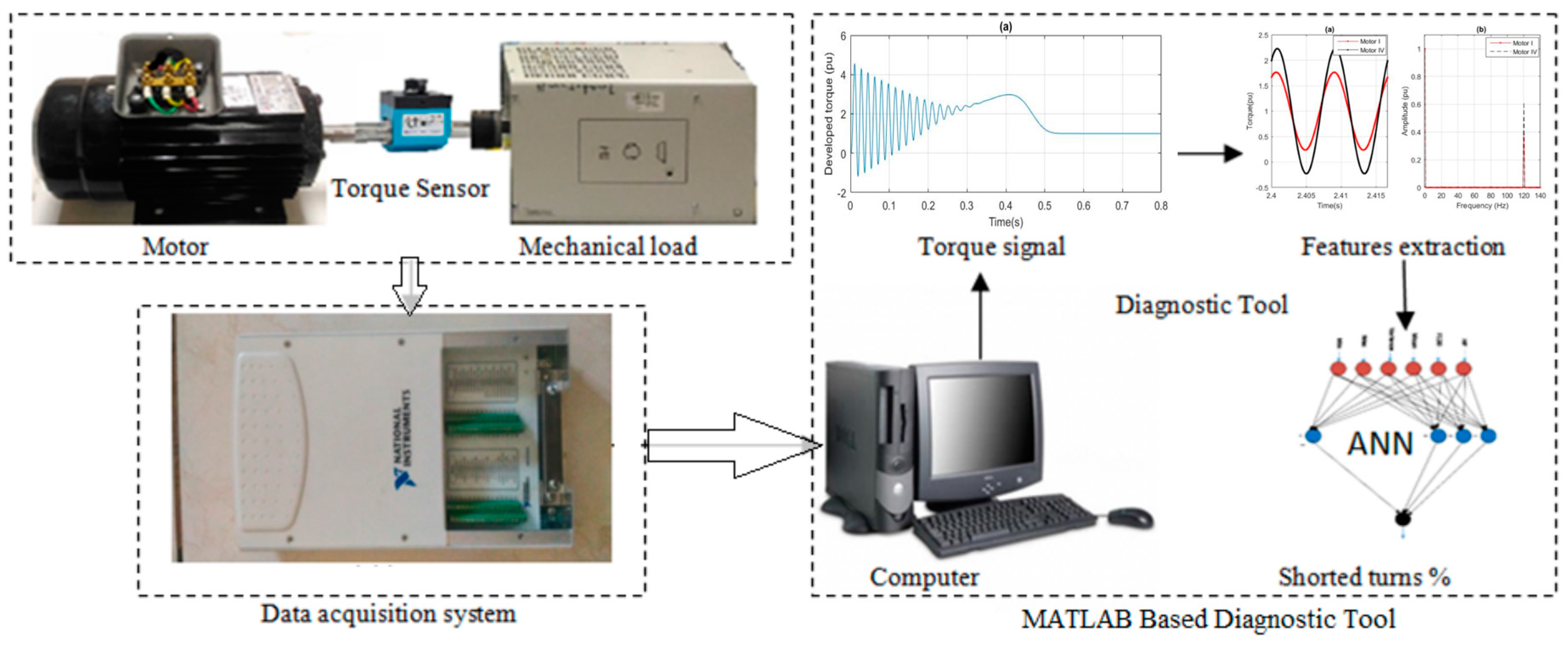
The deployment of the diagnostic tool in reality could be realized as shown in Figure 16. The proposed fault detection tool starts by measuring the torque signal using a torque sensor, which is connected to a computer through a data acquisition system. For the measurement of the torque, either direct or indirect methods can be used. The direct method uses torque sensors as given in [21,29]. In [47,48], the torque was measured with the torque meter DATAFLEX® 22/50 (KTR systems, Rheine, Germany). On the other hand, the indirect method is used for large motors where the torque is obtained through a torque estimator, without the need of a torque sensor. The torque estimator uses the three phase stator currents and voltages in addition to the parameters listed in the nameplates of the motor [18]. In the computer, the captured torque signal undergoes time and frequency domain analysis to extract the desired statistical- and frequency-based features. The extracted features are applied to the trained neural network, which gives the percentage of shorted turns at the end.
7. Conclusions
This paper presents the development of a neural network-based diagnostic tool for detecting the severity and exact percentage of stator inter-turn faults in three-phase induction motors. Simulation results illustrate the advantage of using a steady-state electromechanical torque signature as a fault indicator. When the captured electromechanical torque undergoes time and frequency domain processing, the most representative and distinct inter-turn fault features were found to be variance, max, min, mean, and the F120. The developed neural network is characterized by its simplicity with only one input, one output, and one hidden layer with 11 neurons. In addition, the effectiveness of the developed diagnostics tool was investigated through its application to 100% unseen cases of shorted turns/loading conditions extracted from seen motors with an accuracy of 99% and 100% unseen cases extracted from motors never seen or used for neural network training with an accuracy of 88–96%. This is in contrast to all available diagnostics tools, which can be applied only to motors used in the training process. In future work, the developed diagnostic tool in this paper can be generalized to detect multiple types of faults, such as a combination of inter-turn and broken bar and/or inter-turn and eccentricity. Therefore, this can be used to achieve a comprehensive diagnosis tool. In addition, the deployment of the developed tool in a laboratory environment can be an extension of the present work.
Acknowledgments
The authors would like to acknowledge the support provided by the King Abdul-Aziz City for Science and Technology (KACST) through the Science and Technology Unit at the King Fahd University of Petroleum and Minerals (KFUPM) for funding this work through Project No. 13-ENE403-04 as part of the National Science, Technology and Innovation.
Author Contributions
Luqman Maraaba, Zakariya Al-Hamouz and Mohammad Abido initiated the idea of the Diagnostic tool for different induction motor ratings. Luqman Maraaba implemented the motor simulation model and the diagnostic tool; Luqman Maraaba and Zakariya Al-Hamouz analyzed the data; Luqman Maraaba wrote the paper and Zakariya Al-Hamouz proofread it.
Conflicts of Interest
The authors declare no conflict of interest.
References
- Malekpour, M.; Phung, B.T.; Ambikairajah, E. Online technique for insulation assessment of induction motor stator windings under different load conditions. IEEE Trans. Dielectr. Electr. Insul. 2017, 24, 349–358. [Google Scholar] [CrossRef]
- Choi, S.; Pazouki, E.; Baek, J.; Bahrami, H.R. Iterative Condition Monitoring and Fault Diagnosis Scheme of Electric Motor for Harsh Industrial Application. IEEE Trans. Ind. Electron. 2015, 62, 1760–1769. [Google Scholar] [CrossRef]
- Choi, S.; Haque, M.S.; Arafat, A.; Toliyat, H.A. Detection and Estimation of Extremely Small Fault Signature by Utilizing Multiple Current Sensor Signals in Electric Machines. IEEE Trans. Ind. Appl. 2017, 53, 2805–2816. [Google Scholar] [CrossRef]
- Maraaba, L.; Al-Hamouz, Z.; Milhem, A.; Abido, M. Novel Modeling of Interior-Mount LSPMSM under Asymmetrical Stator Winding. IET Electr. Power Appl. 2018. [Google Scholar] [CrossRef]
- Kim, Y.H.; Youn, Y.W.; Hwang, D.H.; Sun, J.H.; Kang, D.S. High-Resolution Parameter Estimation Method to Identify Broken Rotor Bar Faults in Induction Motors. IEEE Trans. Ind. Electron. 2013, 60, 4103–4117. [Google Scholar] [CrossRef]
- Hong, J.M.; Park, S.U.; Hyun, D.S.; Kang, T.J.; Lee, S.B.; Kral, C. Detection and classification of rotor demagnetization and eccentricity faults for PM synchronous motors. IEEE Trans. Ind. Appl. 2012, 48, 923–932. [Google Scholar] [CrossRef]
- Torkaman, H.; Afjei, E.; Yadegari, P. Static, Dynamic, and Mixed Eccentricity Faults Diagnosis in Switched Reluctance Motors Using Transient Finite Element Method and Experiments. IEEE Trans. Magn. 2012, 48, 2254–2264. [Google Scholar] [CrossRef]
- Arkan, M.; Kostic-Perovic, D.; Unsworth, P.J. Modelling and simulation of induction motors with inter-turn faults for diagnostics. Electr. Power Syst. Res. 2005, 75, 57–66. [Google Scholar] [CrossRef]
- Leite, V.C.M.N.; Borges da Silva, J.G.; Veloso, G.F.C.; Borges da Silva, L.E.; Lambert-Torres, G.; Bonaldi, E.L.; de Oliveira, L.E.d.L. Detection of Localized Bearing Faults in Induction Machines by Spectral Kurtosis and Envelope Analysis of Stator Current. IEEE Trans. Ind. Electron. 2015, 62, 1855–1865. [Google Scholar] [CrossRef]
- Eftekhari, M.; Moallem, M.; Sadri, S.; Shojaei, A. Review of induction motor testing and monitoring methods for inter-turn stator winding faults. In Proceedings of the 2013 21st Iranian Conference on Electrical Engineering (ICEE), Mashhad, Iran, 14–16 May 2013; pp. 1–6. [Google Scholar] [CrossRef]
- Gyftakis, K.N.; Drif, M.; Cardoso, A.J.M. Thorough investigation of the third current harmonic in delta-connected induction motors suffering from a stator inter-turn fault. In Proceedings of the 2015 IEEE 10th International Symposium on Diagnostics for Electrical Machines, Power Electronics and Drives (SDEMPED), Guarda, Portugal, 1–4 September 2015; pp. 7–13. [Google Scholar] [CrossRef]
- Kawady, T.A.; Afify, A.A.; Osheiba, A.M.; Taalab, A.I. Modeling and Experimental Investigation of Stator Winding Faults in Induction Motors. Electr. Power Compon. Syst. 2009, 37. [Google Scholar] [CrossRef]
- Bellini, A.; Filippetti, F.; Tassoni, C.; Capolino, G.A. Advances in Diagnostic Techniques for Induction Machines. IEEE Trans. Ind. Electron. 2008, 55, 4109–4126. [Google Scholar] [CrossRef]
- Rojas, C.; Melero, M.G.; Cabanas, M.F.; Cano, J.M.; Orcajo, G.A.; Pedrayes, F. Finite Element Model for the Study of Inter-Turn Short Circuits in Induction Motors. In Proceedings of the 2007 IEEE International Symposium on Diagnostics for Electric Machines, Power Electronics and Drives, Cracow, Poland, 6–8 September 2007; pp. 415–419. [Google Scholar] [CrossRef]
- Drif, M.; Cardoso, A.J.M. Stator Fault Diagnostics in Squirrel Cage Three-Phase Induction Motor Drives Using the Instantaneous Active and Reactive Power Signature Analyses. IEEE Trans. Ind. Inform. 2014, 10, 1348–1360. [Google Scholar] [CrossRef]
- Eftekhari, M.; Moallem, M.; Sadri, S.; Hsieh, M. A novel indicator of stator winding inter-turn fault in induction motor using infrared thermal imaging. Infrared Phys. Technol. 2013, 61, 330–336. [Google Scholar] [CrossRef]
- Lashkari, N.; Poshtan, J.; Azgomi, H.F. Simulative and experimental investigation on stator winding turn and unbalanced supply voltage fault diagnosis in induction motors using Artificial Neural Networks. ISA Trans. 2015, 59, 334–342. [Google Scholar] [CrossRef] [PubMed]
- da Silva, A.M.; Povinelli, R.J.; Demerdash, N.A.O. Rotor Bar Fault Monitoring Method Based on Analysis of Air-Gap Torques of Induction Motors. IEEE Trans. Ind. Inform. 2013, 9, 2274–2283. [Google Scholar] [CrossRef]
- Kato, T.; Inoue, K.; Yoshida, K. Diagnosis of Stator-Winding-Turn Faults of Induction Motor by Direct Detection of Negative Sequence Currents. Electr. Eng. Jpn. 2014, 186, 75–84. [Google Scholar] [CrossRef]
- Urresty, J.C.; Riba, J.R.; Delgado, M.; Romeral, L. Detection of Demagnetization Faults in Surface-Mounted Permanent Magnet Synchronous Motors by Means of the Zero-Sequence Voltage Component. IEEE Trans. Energy Convers. 2012, 27, 42–51. [Google Scholar] [CrossRef]
- Gyftakis, K.N.; Spyropoulos, D.V.; Kappatou, J.C.; Mitronikas, E.D. A Novel Approach for Broken Bar Fault Diagnosis in Induction Motors Through Torque Monitoring. IEEE Trans. Energy Convers. 2013, 28, 267–277. [Google Scholar] [CrossRef]
- Filho, P.C.M.L.; Pederiva, R.; Brito, J.N. Detection of stator winding faults in induction machines using flux and vibration analysis. Mech. Syst. Signal Process. 2014, 42, 377–387. [Google Scholar] [CrossRef]
- Jelassi, S.; Romary, R.; Brudny, J. Vibro-acoustic behaviour of an induction machine with stator inter-turn short-circuit. Eur. Phys. J. Appl. Phys. 2016, 73, 10904. [Google Scholar] [CrossRef]
- Glowacz, A.; Glowacz, W.; Glowacz, Z.; Kozik, J. Early fault diagnosis of bearing and stator faults of the single-phase induction motor using acoustic signals. Measurement 2018, 113, 1–9. [Google Scholar] [CrossRef]
- Singh, G.; Naikan, V.N.A. Infrared thermography baseddiagnosis of inter-turn fault and cooling system failure in three phase induction motor. Infrared Phys. Technol. 2017, 87, 134–138. [Google Scholar] [CrossRef]
- Glowacz, A.; Glowacz, Z. Diagnosis of stator faults of the single-phase induction motor using acoustic signals. Appl. Acoust. 2017, 117, 20–27. [Google Scholar] [CrossRef]
- Delgado-Arredondo, P.A.; Morinigo-Sotelo, D.; Osornio-Rios, R.A.; Avina-Cervantes, J.G.; Rostro-Gonzalez, H.; Romero-Troncoso, R.d.J. Methodology for fault detection in induction motors via sound and vibration signals. Mech. Syst. Signal Process. 2017, 83, 568–589. [Google Scholar] [CrossRef]
- Glowacz, A.; Głowacz, Z.; Glowacz, W.; Carletti, E.; Kozik, J.; Korenciak, D.; Gutten, M.; Khan, F.; Irfant, M. Fault Diagnosis of Three Phase Induction Motor Using Current Signal, MSAF-Ratio15 and Selected Classifiers. Arch. Metall. Mater. 2017, 62, 2413–2419. [Google Scholar] [CrossRef]
- Hsu, J.S. Monitoring of defects in induction motors through air-gap torque observation. IEEE Trans. Ind. Appl. 1995, 31, 1016–1021. [Google Scholar] [CrossRef]
- Toliyat, H.A.; Lipo, T.A. Transient analysis of cage induction machines under stator, rotor bar and end ring faults. IEEE Trans. Energy Convers. 1995, 10, 241–247. [Google Scholar] [CrossRef]
- Pietrowski, W.; Górny, K. Wavelet analysis of torque at startup of an induction machine under inter-turn short-circuit. In Proceedings of the 2017 International Symposium on Electrical Machines (SME), Naleczow, Poland, 18–21 June 2017; pp. 1–4. [Google Scholar] [CrossRef]
- Zhang, K.; Yuan, F.; Guo, J.; Wang, G. A novel neural network approach to transformer fault diagnosis based on momentum-embedded BP neural network optimized by genetic algorithm and fuzzy c-means. Arab. J. Sci. Eng. 2016, 41, 3451–3461. [Google Scholar] [CrossRef]
- Prasad, A.; Edward, J.B. Importance of artificial neural networks for location of faults in transmission systems: A survey. In Proceedings of the 2017 11th International Conference on Intelligent Systems and Control (ISCO), Coimbatore, India, 5–6 January 2017; pp. 357–362. [Google Scholar] [CrossRef]
- Nag, A.; Yadav, A. Fault classification using Artificial Neural Network in combined underground cable and overhead line. In Proceedings of the 2016 IEEE 1st International Conference on Power Electronics, Intelligent Control and Energy Systems (ICPEICES), Delhi, India, 4–6 July 2016; pp. 1–4. [Google Scholar] [CrossRef]
- Chine, W.; Mellit, A.; Lughi, V.; Malek, A.; Sulligoi, G.; Pavan, A.M. A novel fault diagnosis technique for photovoltaic systems based on artificial neural networks. Renew. Energy 2016, 90, 501–512. [Google Scholar] [CrossRef]
- Palácios, R.H.C.; Silva, I.N.; Goedtel, A.; Godoy, W.F. A comprehensive evaluation of intelligent classifiers for fault identification in three-phase induction motors. Electr. Power Syst. Res. 2015, 127, 249–258. [Google Scholar] [CrossRef]
- Wolkiewicz, M.; Kowalski, C.T. Incipient stator fault detector based on neural networks end symmetrical components analysis for induction motor drives. In Proceedings of the 2016 13th Selected Issues of Electrical Engineering and Electronics (WZEE), Rzeszow, Poland, 4–8 May 2016; pp. 1–7. [Google Scholar] [CrossRef]
- Joksimovic, G.M.; Penman, J. The detection of inter-turn short circuits in the stator windings of operating motors. IEEE Trans. Ind. Electron. 2000, 47, 1078–1084. [Google Scholar] [CrossRef]
- Rodríguez, P.V.J.; Arkkio, A. Detection of stator winding fault in induction motor using fuzzy logic. Appl. Soft Comput. 2008, 8, 1112–1120. [Google Scholar] [CrossRef]
- Bouzid, M.B.K.; Champenois, G.; Bellaaj, N.M.; Signac, L.; Jelassi, K. An Effective Neural Approach for the Automatic Location of Stator Interturn Faults in Induction Motor. IEEE Trans. Ind. Electron. 2008, 55, 4277–4289. [Google Scholar] [CrossRef]
- Lashkari, N.; Poshtan, J. Detection and discrimination of stator interturn fault and unbalanced supply voltage fault in induction motor using neural network. In Proceedings of the 6th Power Electronics, Drive Systems & Technologies Conference (PEDSTC2015), Tehran, Iran, 3–4 February 2015; pp. 275–280. [Google Scholar] [CrossRef]
- Bazan, G.H.; Scalassara, P.R.; Endo, W.; Goedtel, A.; Godoy, W.F.; Palácios, R.H.C. Stator fault analysis of three-phase induction motors using information measures and artificial neural networks. Electr. Power Syst. Res. 2017, 143, 347–356. [Google Scholar] [CrossRef]
- Ghate, V.N.; Dudul, S.V. Optimal MLP neural network classifier for fault detection of three phase induction motor. Expert Syst. Appl. 2010, 37, 3468–3481. [Google Scholar] [CrossRef]
- Ghate, V.N.; Dudul, S.V. Cascade Neural-Network-Based Fault Classifier for Three-Phase Induction Motor. IEEE Trans. Ind. Electron. 2011, 58, 1555–1563. [Google Scholar] [CrossRef]
- Martins, J.F.; Pires, V.F.; Pires, A.J. Unsupervised Neural-Network-Based Algorithm for an On-Line Diagnosis of Three-Phase Induction Motor Stator Fault. IEEE Trans. Ind. Electron. 2007, 54, 259–264. [Google Scholar] [CrossRef]
- Leedy, A. Simulink/MATLAB dynamic induction motor model for use in undergraduate electric machines and power electronics courses. In Proceedings of the 2013 IEEE Southeastcon, Jacksonville, FL, USA, 4–7 April 2013; pp. 1–6. [Google Scholar] [CrossRef]
- Zając, M.; Sułowicz, M. The detection of coil shorting in induction motors by means of wavelet analysis. Tech. Trans. Electr. Eng. 2016, 135–150. [Google Scholar] [CrossRef]
- Zając, M.; Sułowicz, M. Detection of coil shorting in an induction motor by means of wavelet detectors based on orthogonal Legendre polynomials. In Proceedings of the 2017 International Symposium on Electrical Machines (SME), Naleczow, Poland, 18–21 June 2017; pp. 1–6. [Google Scholar] [CrossRef]
Figure 1.
Flow chart for stator inter-turn fault diagnostic technique.

Figure 2.
Induction motor with inter-turns circuit diagram.

Figure 3.
Motor I simulation result at full load for a healthy motor: (a) developed torque and (b) rotor speed.
Figure 3.
Motor I simulation result at full load for a healthy motor: (a) developed torque and (b) rotor speed.

Figure 4.
Developed torque for Motor I and Motor IV at full load for the healthy case.
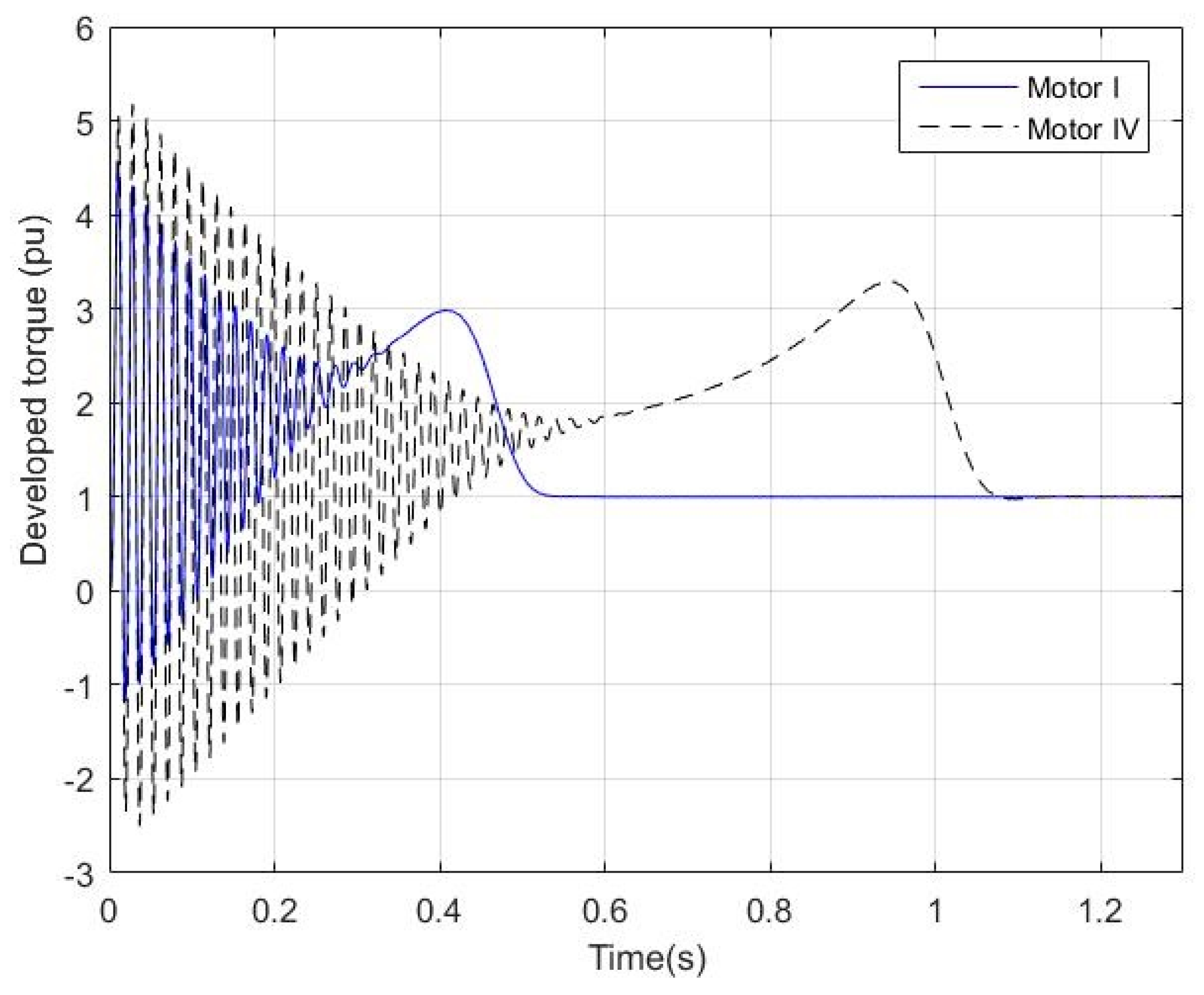
Figure 5.
Three-phase stator current of Motor I at full load: (a) 0% shorted turns and (b) 10% shorted turns, blue: phase-a; red: phase-b; yellow: phase-c.
Figure 5.
Three-phase stator current of Motor I at full load: (a) 0% shorted turns and (b) 10% shorted turns, blue: phase-a; red: phase-b; yellow: phase-c.
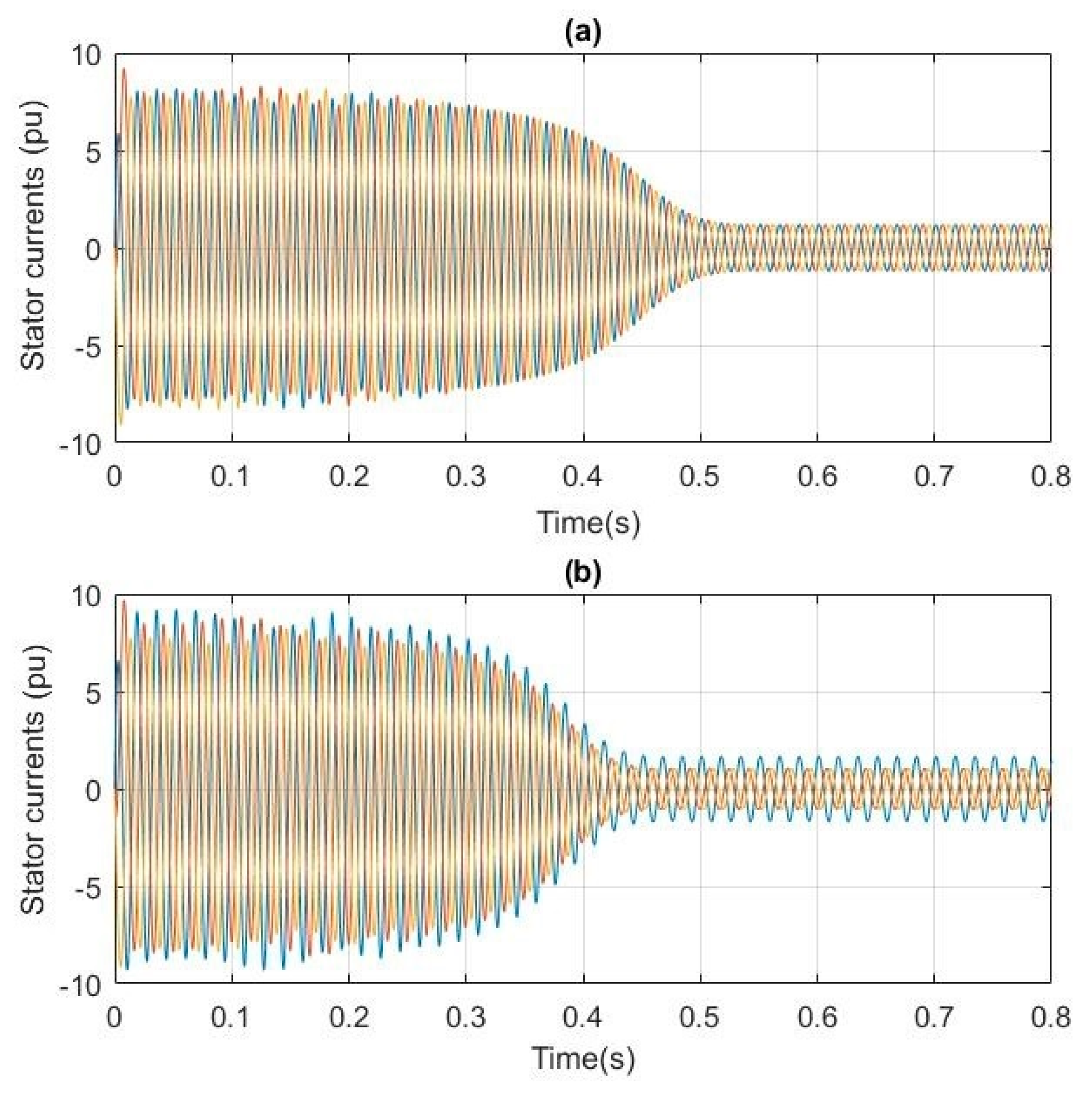
Figure 6.
Developed torque of Motor I at full load.

Figure 7.
Developed torque for Motor I and Motor 4 at full load with 5% shorted turns.
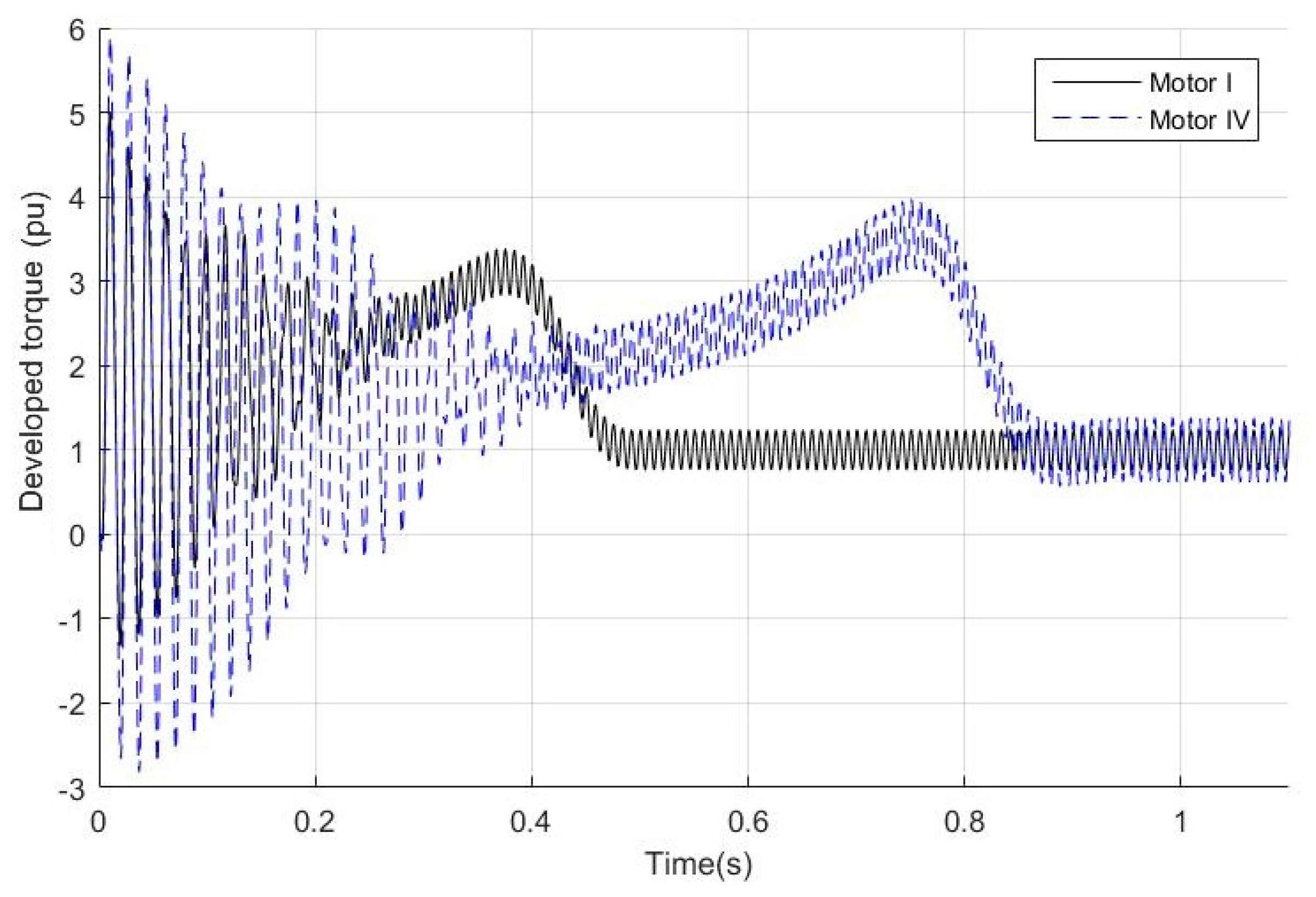
Figure 8.
Motor I developed torque at full load: (a,c,e) show the torque time response; while (b,d,f) show the torque spectra.
Figure 8.
Motor I developed torque at full load: (a,c,e) show the torque time response; while (b,d,f) show the torque spectra.
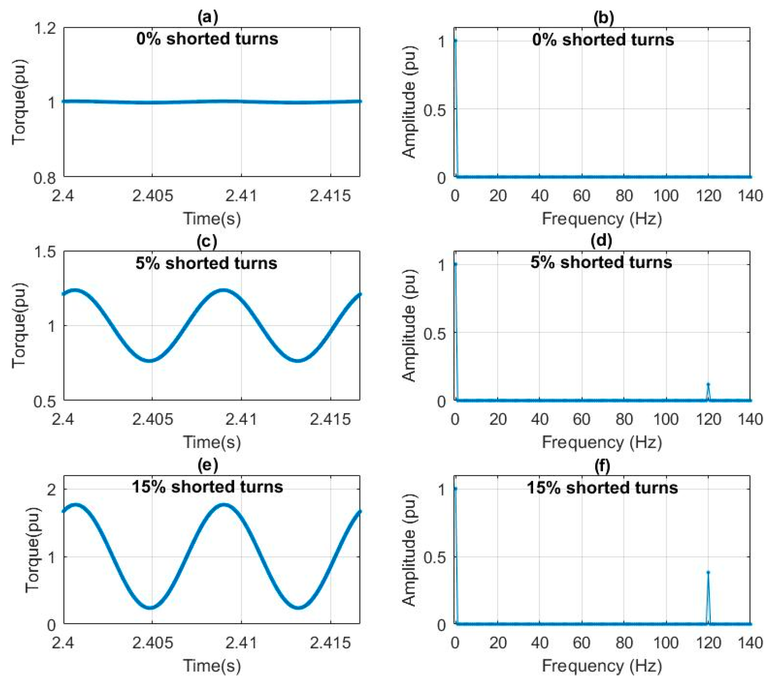
Figure 9.
Developed torque at full load for Motor I and Motor IV with 15% shorted turns showing: (a) torque time response; and (b) torque spectra.
Figure 9.
Developed torque at full load for Motor I and Motor IV with 15% shorted turns showing: (a) torque time response; and (b) torque spectra.
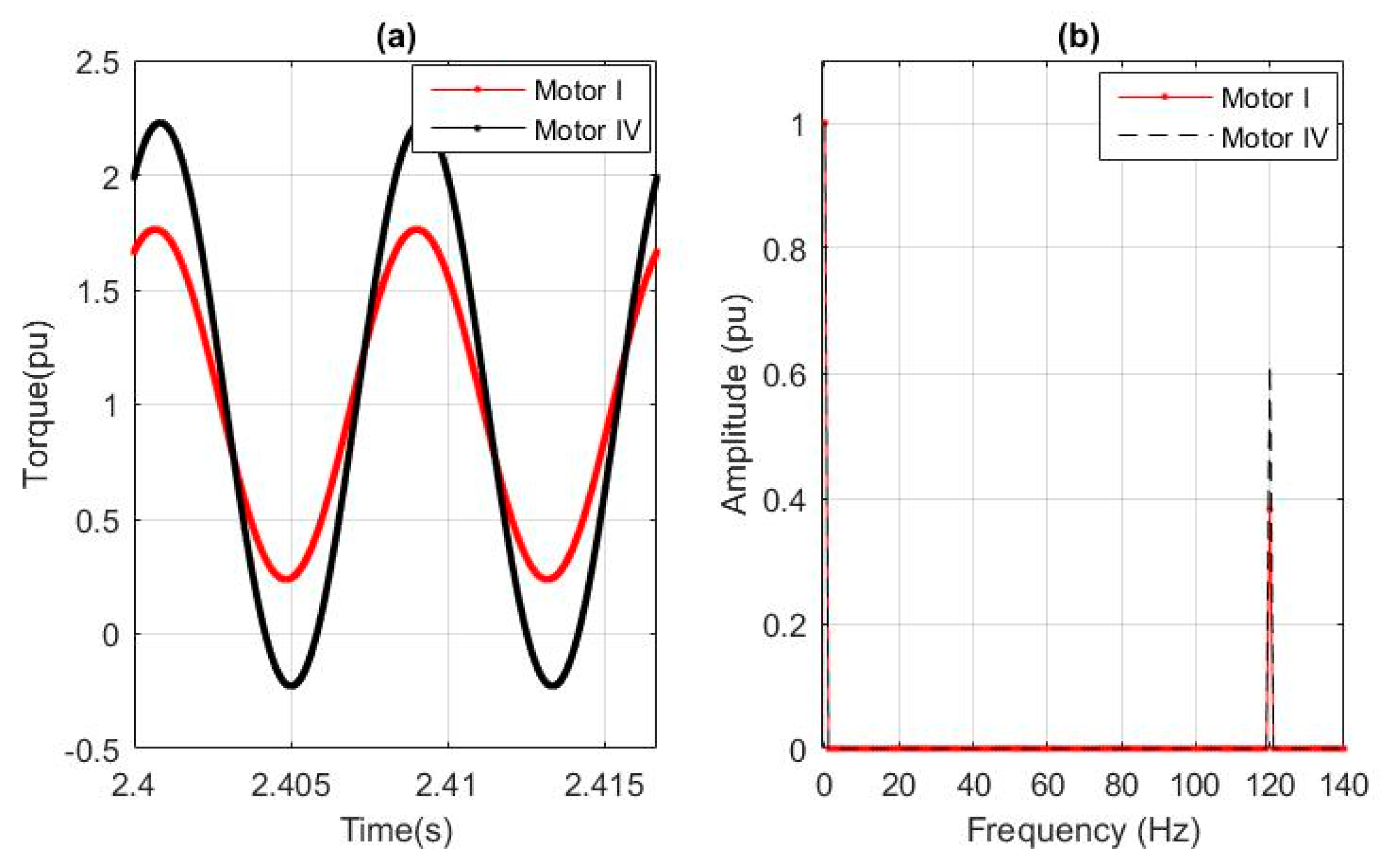
Figure 10.
F120 and variance versus shorted turns percentage for Motor I, including: (a) F120 and (b) variance.
Figure 10.
F120 and variance versus shorted turns percentage for Motor I, including: (a) F120 and (b) variance.
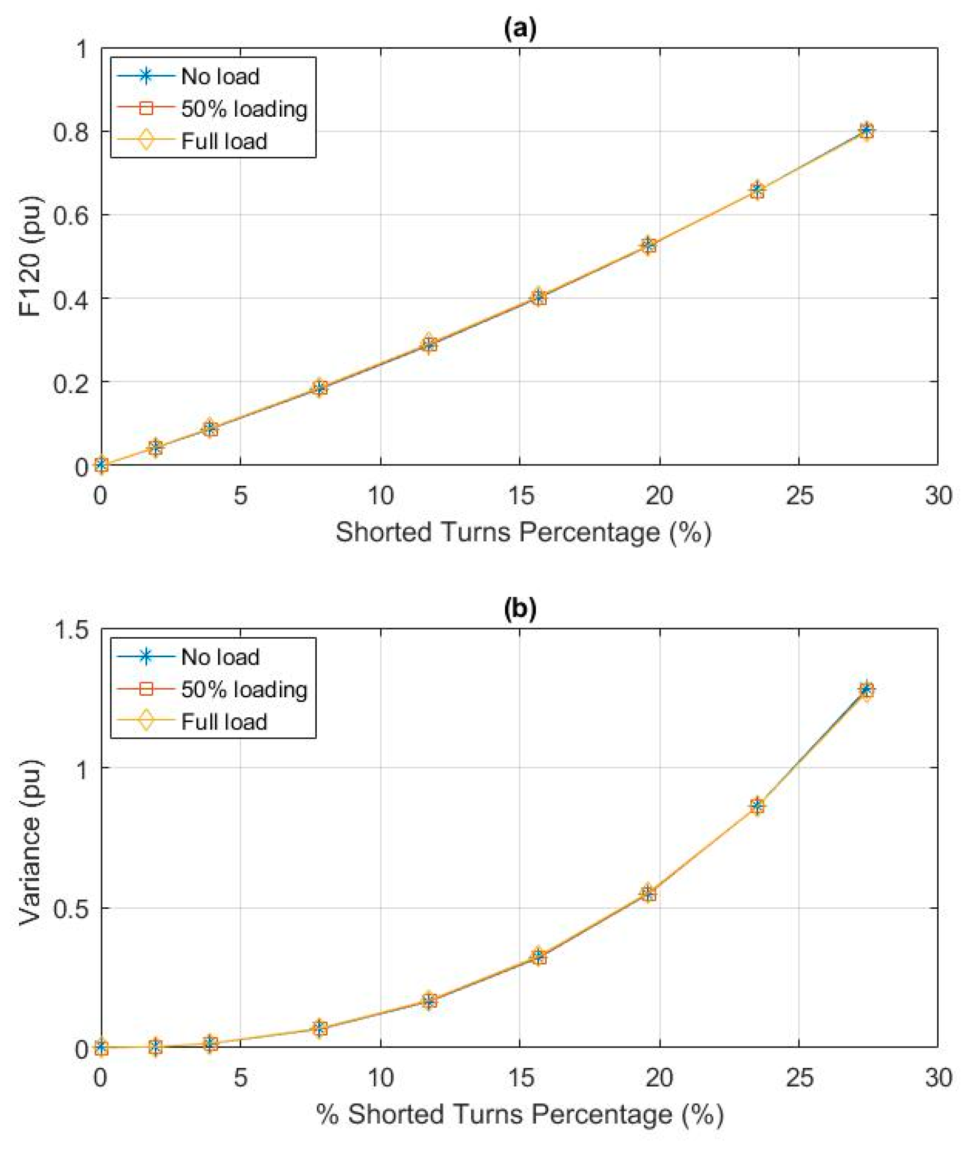
Figure 11.
F120 and variance dependence on the percentage of shorted turns at full load for: (a) F120 and (b) variance.
Figure 11.
F120 and variance dependence on the percentage of shorted turns at full load for: (a) F120 and (b) variance.

Figure 12.
Comparison of parameters against the shorted turns percentage for Motor I, including: (a) max, (b) min and (c) mean.
Figure 12.
Comparison of parameters against the shorted turns percentage for Motor I, including: (a) max, (b) min and (c) mean.
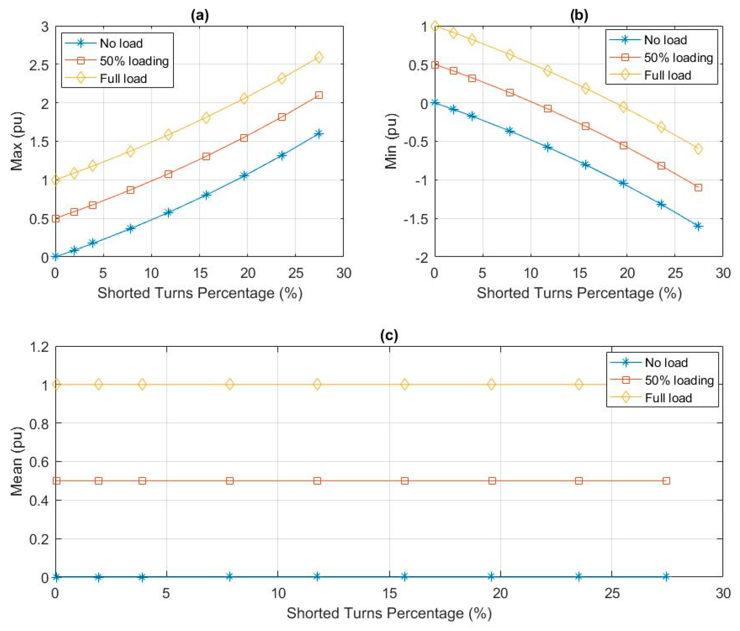
Figure 13.
Comparison against shorted turns percentage at full load for: (a) max, (b) min and (c) mean.
Figure 13.
Comparison against shorted turns percentage at full load for: (a) max, (b) min and (c) mean.
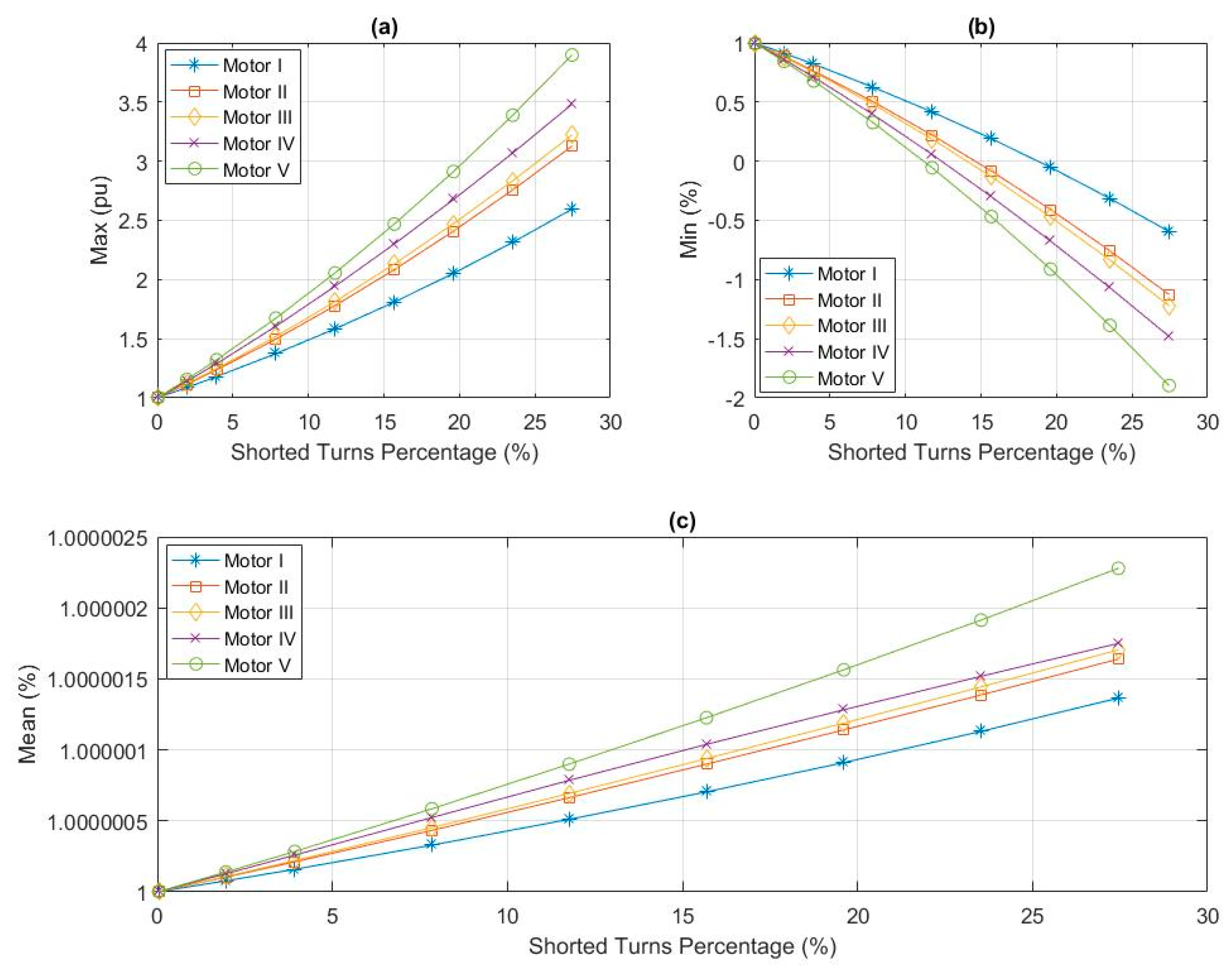
Figure 14.
The designed neural network.
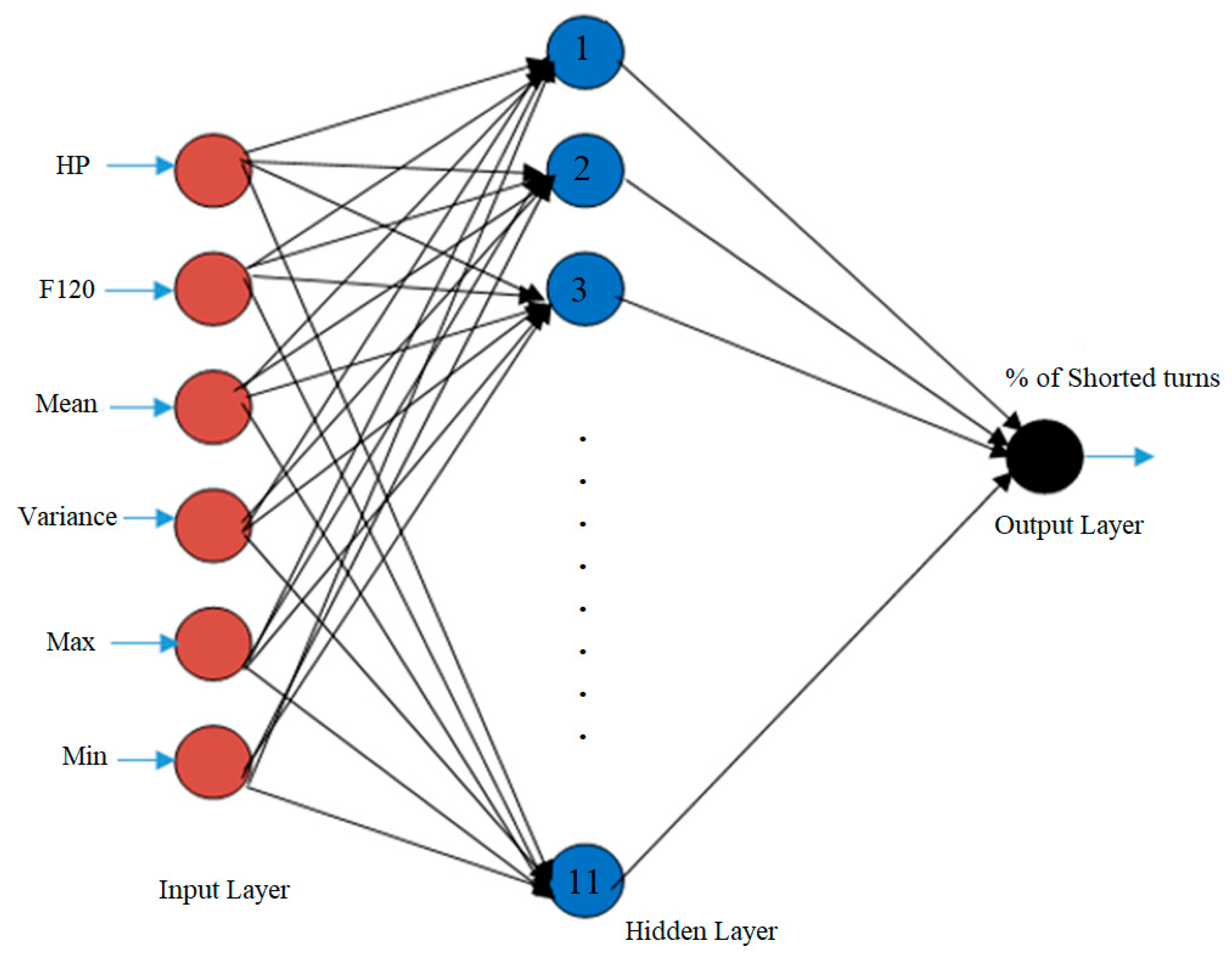
Figure 15.
Training phase performance.

Figure 16.
Diagnostic tool deployment.


Table 1.
Motor Parameters.
| Motor I [8] | Motor II | Motor III | Motor IV | Motor V [46] | |
|---|---|---|---|---|---|
| Power (hp) | 2 | 5 | 10 | 20 | 50 |
| Voltage (volt) | 460 | 460 | 460 | 460 | 460 |
| Speed (rpm) | 1752 | 1750 | 1760 | 1760 | 1780 |
| P | 4 | 4 | 4 | 4 | 4 |
| f (Hz) | 60 | 60 | 60 | 60 | 60 |
| rs (Ω) | 4.05 | 1.115 | 0.683 | 0.276 | 0.087 |
| Lσs (mH) | 13.97 | 5.974 | 4.152 | 2.191 | 0.8 |
| rr (Ω) | 2.6 | 1.083 | 0.451 | 0.164 | 0.228 |
| Lσr (mH) | 13.97 | 5.974 | 4.152 | 2.19 | 0.8 |
| Lm (mH) | 538.6 | 203.7 | 148.6 | 76.14 | 34.7 |
| J (kg m2) | 0.06 | 0.02 | 0.05 | 0.1 | 1.662 |
Table 2.
Testing motors parameters.
| Motor VI | Motor VII | |
|---|---|---|
| Power (hp) | 10 | 50 |
| Voltage (volt) | 575 | 460 |
| Speed (rpm) | 1760 | 1780 |
| P | 4 | 4 |
| f (Hz) | 60 | 60 |
| rs (Ω) | 0.9174 | 0.0996 |
| Lσs (mH) | 5.473 | 0.867 |
| rr (Ω) | 0.6258 | 0.05837 |
| Lσr (mH) | 5.473 | 0.867 |
| Lm (mH) | 185.4 | 30.39 |
| J (kg m2) | 0.05 | 0.4 |
Table 3.
Testing results.
| Motor | Motor Power (Hp) | Fault-Load Cases | Accuracy Rate |
|---|---|---|---|
| Motor I | 2 | 20 | 99.9985% |
| Motor II | 5 | 20 | 99.8601% |
| Motor III | 10 | 20 | 99.9853% |
| Motor IV | 20 | 20 | 99.9326% |
| Motor V | 50 | 20 | 99.9146% |
| Motor VI | 10 | 50 | 96.5338% |
| Motor VII | 50 | 50 | 88.2972% |
© 2018 by the authors. Licensee MDPI, Basel, Switzerland. This article is an open access article distributed under the terms and conditions of the Creative Commons Attribution (CC BY) license (http://creativecommons.org/licenses/by/4.0/).
Share and Cite
MDPI and ACS Style
Maraaba, L.; Al-Hamouz, Z.; Abido, M. An Efficient Stator Inter-Turn Fault Diagnosis Tool for Induction Motors. Energies 2018, 11, 653. https://doi.org/10.3390/en11030653
AMA Style
Maraaba L, Al-Hamouz Z, Abido M. An Efficient Stator Inter-Turn Fault Diagnosis Tool for Induction Motors. Energies. 2018; 11(3):653. https://doi.org/10.3390/en11030653
Chicago/Turabian StyleMaraaba, Luqman, Zakariya Al-Hamouz, and Mohammad Abido. 2018. "An Efficient Stator Inter-Turn Fault Diagnosis Tool for Induction Motors" Energies 11, no. 3: 653. https://doi.org/10.3390/en11030653
Note that from the first issue of 2016, this journal uses article numbers instead of page numbers. See further details here.