1. Introduction
Due to the increasing cost of rare-earth magnetic materials, as well as the need of high flux-weakening performance of motors in electrical and hybrid vehicles, brushless electrical excitation topologies for wound-rotor synchronous machines (WRSMs) have received increasing research attention to replace the brushes and slip rings assembly in conventional WRSMs. Several brushless excitation techniques for WRSMs have been proposed [
1,
2,
3]. In large synchronous machines such as steam or water turbine generators, an additional brushless exciter is utilized for rotor field excitation [
4,
5]. However, in small and medium sized electrical machines for electric or hybrid vehicles and other industry applications, it is not suitable to use a separate brushless exciter due to limitation of volume and cost. Therefore, for such applications, permanent magnet (PM) machines and induction machines are widely used [
6,
7,
8,
9]. However, PM machines have an inherent deficiency, which is the lack of excitation control for wide-speed applications such as traction applications. Therefore, a flux-weakening operation is performed to operate PM machines for high speed applications [
10,
11,
12,
13].
Considering these issues with existing WRSMs and PM machines, purely electrically self-excited and brushless three phase synchronous machines have been studied [
14,
15,
16,
17]. In these brushless wound-rotor synchronous machines (BL-WRSMs), the synchronous machine itself is used as an excitation, as well as torque-producing device. The main advantage of these BL-WRSMs is that the brushes and slip ring assembly were eliminated. Moreover, the field weakening operation of these self-excited machines for wide speed operations is very simple because the field current of the machine can be controlled by modulating the stator current only. In [
15,
16], a third harmonic component of stator MMF was utilized to induce the voltage in the harmonic winding placed on the rotor. This induced voltage was then rectified, and the current was supplied to the field winding of the machine for brushless operation. In [
17], a dual inverter brushless topology was presented for which the subharmonic component of the stator MMF was used to excite the field winding of the machine. However, this method uses two inverters to excite the stator of the machine for brushless operation of the WRSM, which increases the cost and size of the brushless excitation system and makes this topology less suitable for practical applications.
Based on the dual inverter brushless topology presented in [
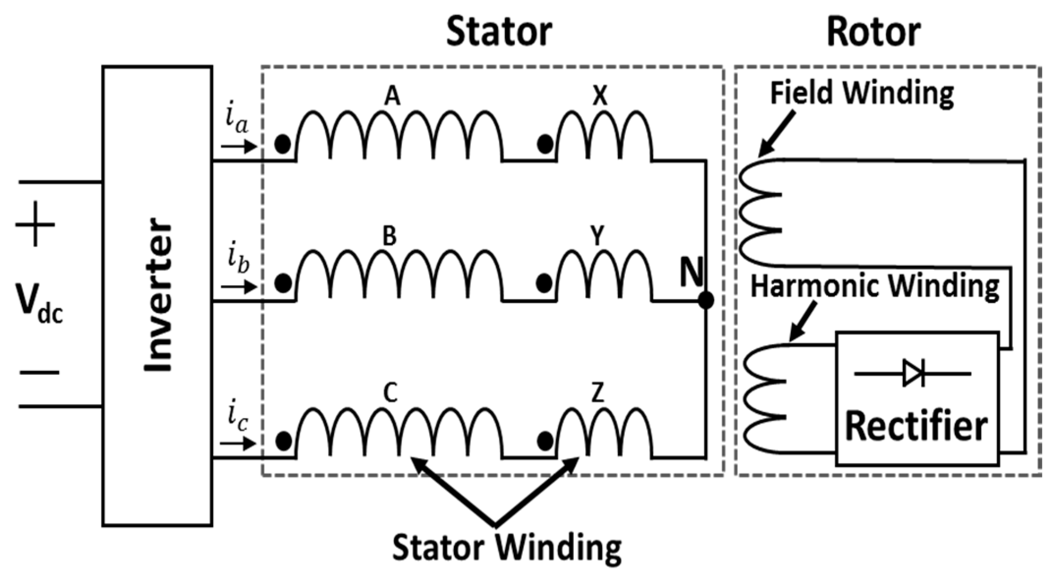
17], recently a new single inverter-fed brushless wound-rotor synchronous machine using a special stator-winding arrangement was introduced in [
18,
19], which is shown in
Figure 1.
The brushless operation of the WRSM was achieved by generating an additional subharmonic component (along with the fundamental component) in the stator: magneto motive force (MMF). This was achieved by supplying the three-phase sinusoidal currents through a single three-phase inverter to the specially designed stator winding. The stator winding of the BL-WRSM is divided into two sets of series connected windings, such that one set of the windings has twice as many turns compared to the other.
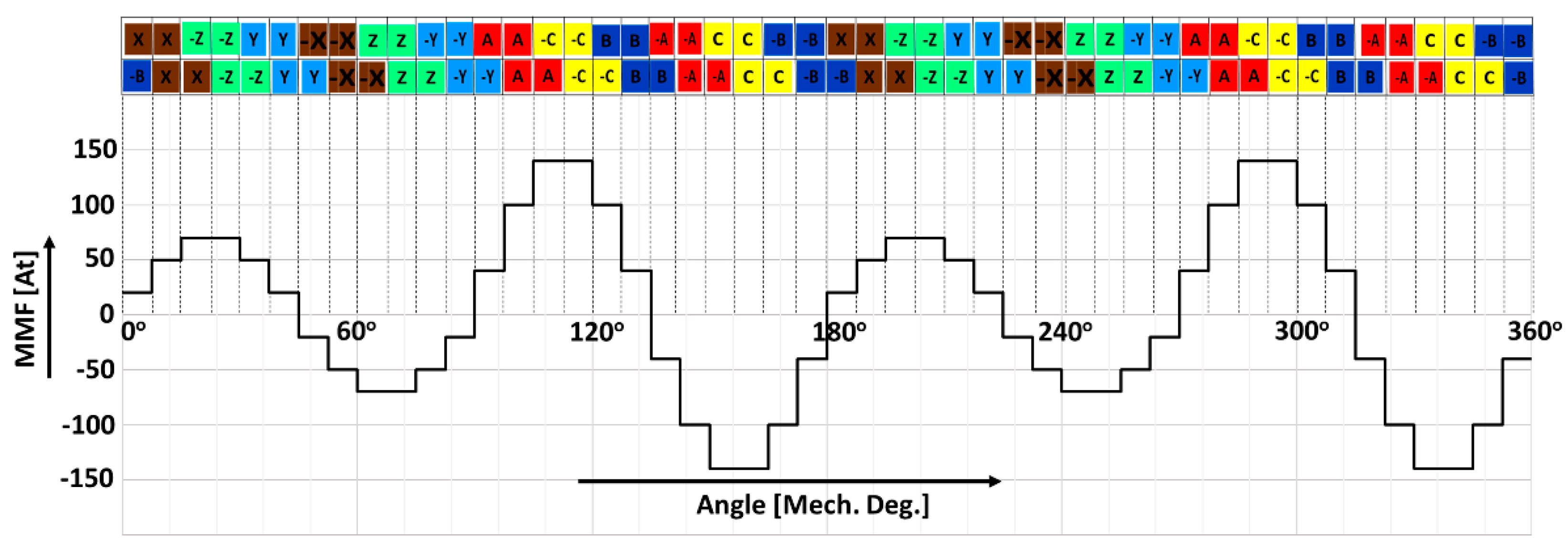
The winding distribution of the BL-WRSM along with the stator MMF is shown in
Figure 2, for the case where phase-A current in the stator winding has the maximum amplitude and the winding ABC has double the number of turns per phase compared to the winding XYZ. The MMF plot is comprised of two dominant components, (1) the fundamental component and (2) the subharmonic component. The subharmonic component of the stator MMF is responsible for inducing the voltage in the four-pole harmonic winding placed on the rotor. This induced voltage is then rectified through a rectifier mounted on the rotor, which is then supplied to the eight-pole main field winding for the brushless operation of the machine. The main advantage of this BL-WRSM is that it requires only one three-phase inverter to supply the currents to the stator winding of the machine, which makes it suitable for variable speed applications.
This paper presents the optimal design of the BL-WRSM. The machine was optimized by using the Kriging method based on Latin hypercube sampling and a Genetic algorithm (GA) [
20]. The optimal design was verified using the 2-D finite element analysis (FEA) by the aid of ANSYS Maxwell. Moreover, the BL-WRSM was analyzed over a wide speed range to verify the suitability of the proposed BL-WRSM for variable speed applications. Finally, the optimal model of BL-WRSM was fabricated and tested to verify the operation of the single inverter-fed brushless topology.
3. 2D-Finite Element Analysis (FEA) and Rotor Pole Shape Optimization
3.1. 2-D FEA of Basic Model
A 2-D FEA was utilized to analyze the performance of the proposed BL-WRSM by supplying the rated current of 4.5 Arms at 60 Hz frequency to the three-phase stator windings. For the simulation analysis, three-phase sinusoidal current is directly applied to stator winding and the rotor speed has been set constant at 900 rpm, as required by the synchronism constraint.
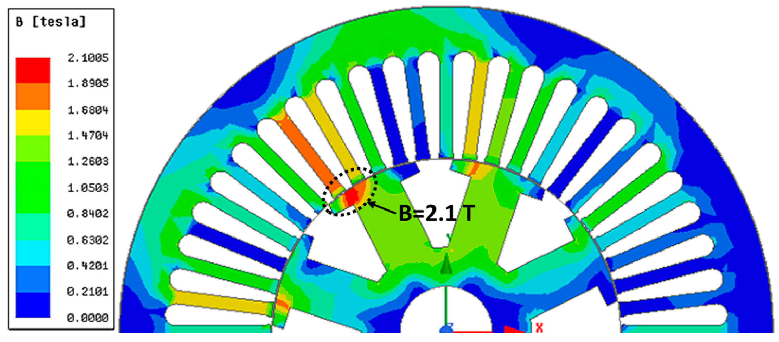
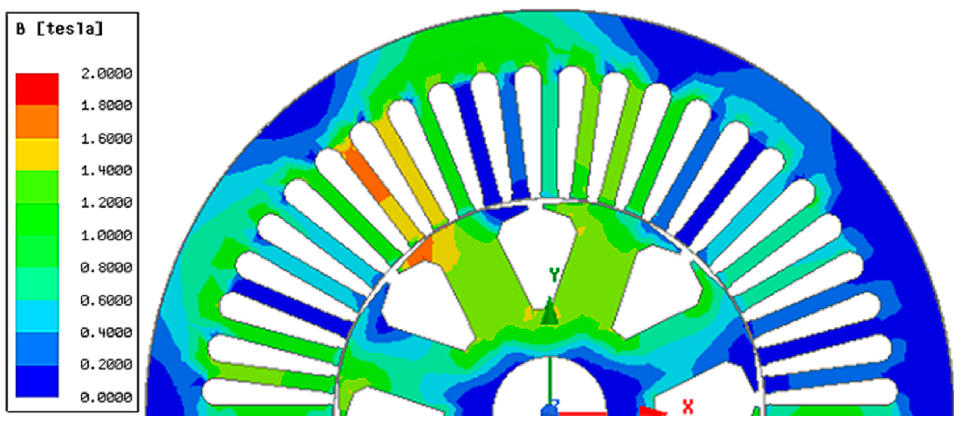
Figure 4 shows the flux density (B) of the half-model of the machine plotted at the rated load case. The flux density is higher on the portion of the machine with winding ABC compared with that of winding XYZ. The difference in flux density magnitude is due to the double number of turns in the winding ABC compared to that of the winding XYZ. It also shows that most of the machine is working under the flux density of 2 T. However, one of the pole shoes showed saturation at 2.1 T, which will be decreased to less than 2 T by rotor pole shape optimization.
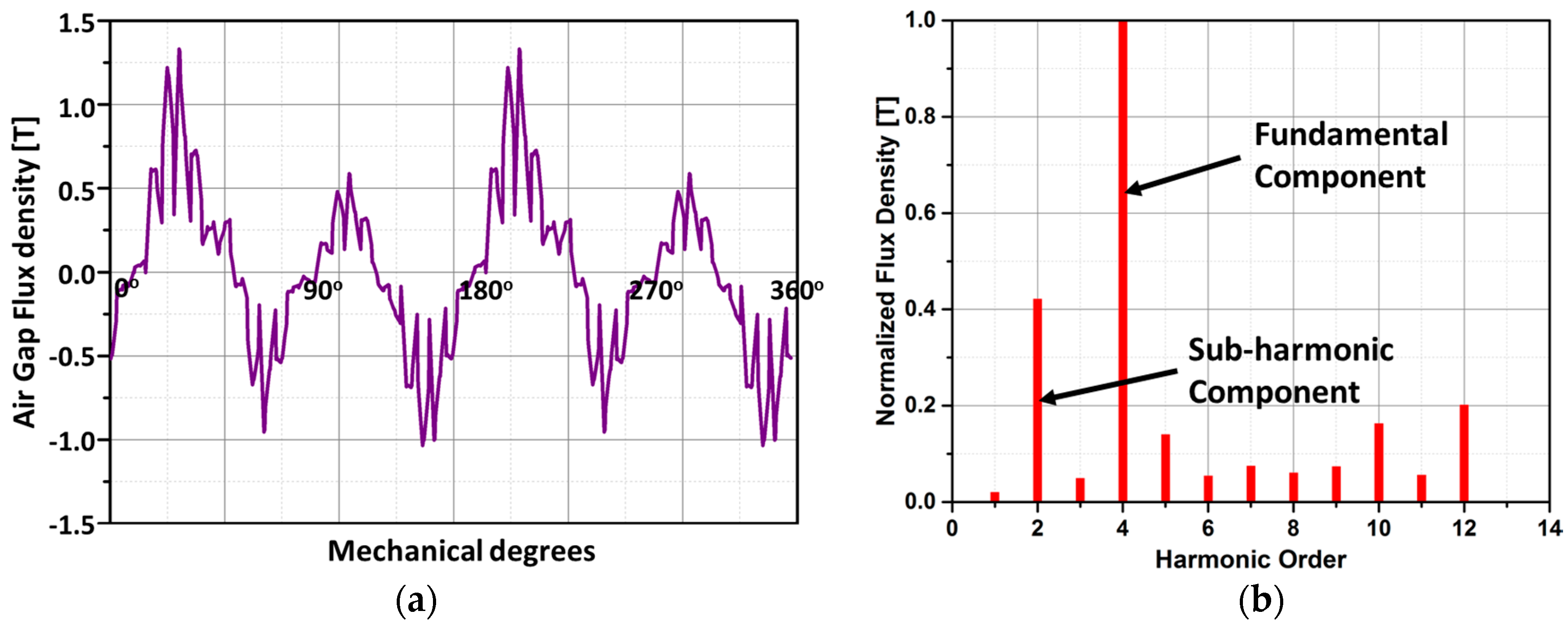
The air gap flux density plot is shown in
Figure 5a. The difference in the peak values of the air gap flux density is due to the special winding arrangement used for the proposed brushless topology. The harmonic order for the normalized flux density is shown in
Figure 5b. It demonstrates 2-pole pairs of the subharmonic component of the stator MMF and the 4-pole pairs of the fundamental component of stator MMF.
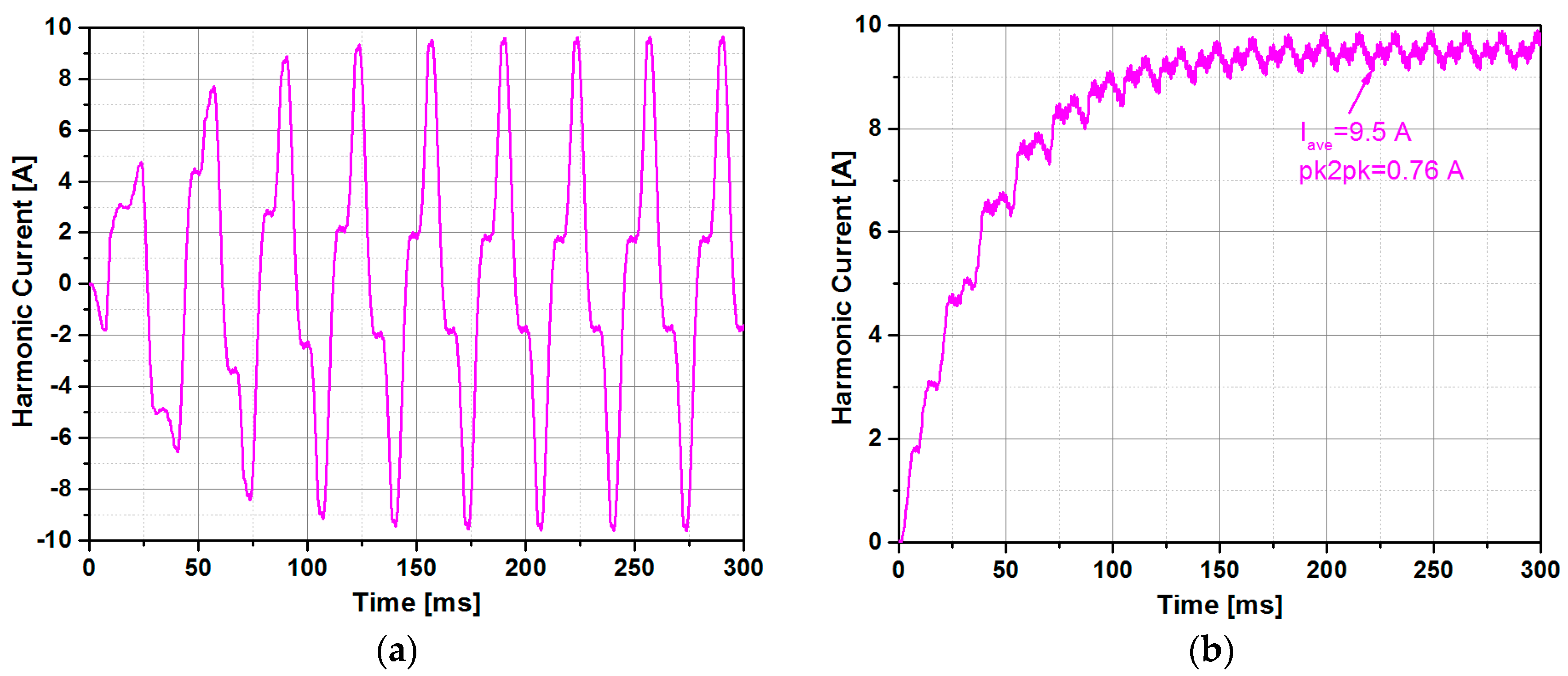
The subharmonic component of the stator MMF induces alternating voltage in the harmonic winding. This induced voltage is rectified to provide DC current to the field winding of the machine. The rotor currents in the harmonic winding and the field winding is shown in
Figure 6a,b respectively. The average value of the field current in the steady state is 9.5 A with a peak-to-peak value of 0.76 A, which results in 8% ripples in the field current. It can be observed that after rectification, the harmonic winding voltage is able to establish a stable excitation current in the field winding, which confirms the feasibility of the proposed brushless topology.
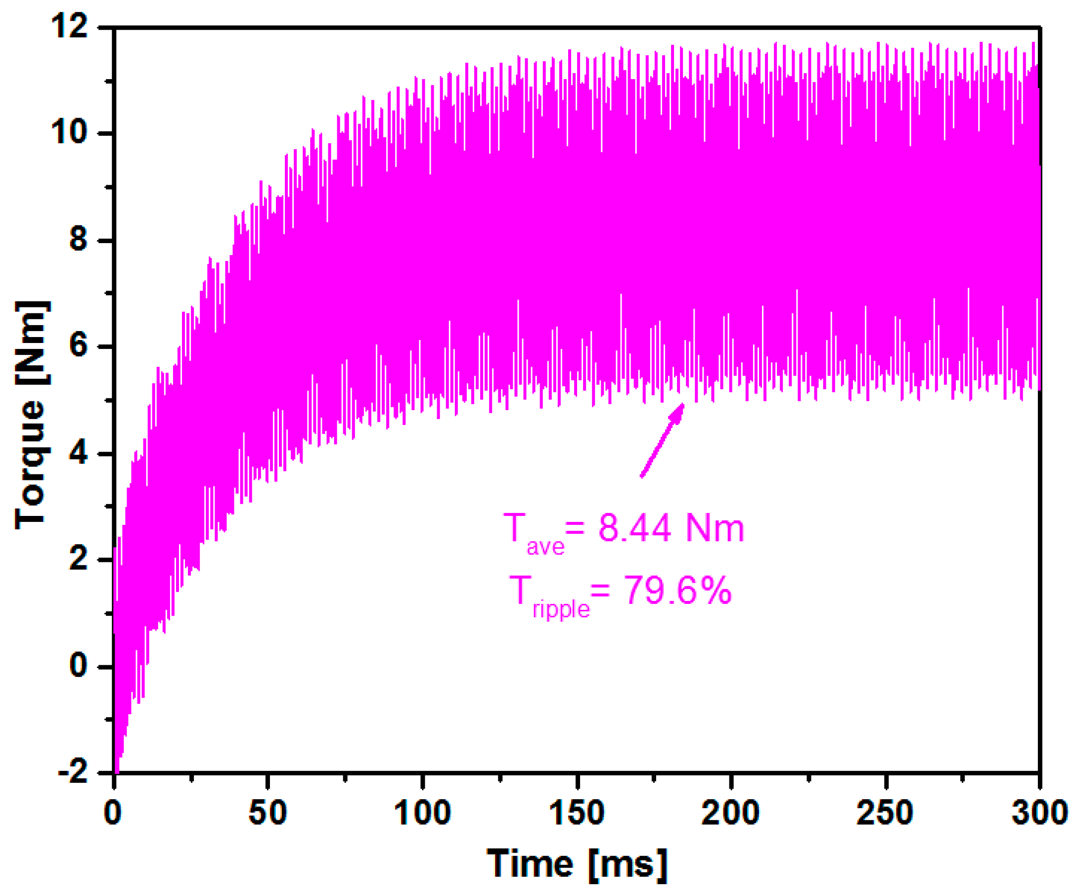
Figure 7 shows the torque of the basic BL-WRSM model. The machine achieved the steady state at 150 ms and an average torque of 8.44 Nm with a torque ripple of 79.6% is observed. This shows that the basic model of the BL-WRSM is not exhibiting the best performance in terms the output torque. The performance of the basic model is improved by optimizing the rotor pole shape. For optimization, the Kriging method based on Latin hypercube sampling and a Genetic algorithm was used. The details of the optimization method are discussed in the following section.
3.2. Rotor Pole Shape Optimization
The pole shape in the salient pole machines is the most crucial factor, which affects the torque characteristics of the machine [
21,
22]. Therefore, the rotor pole span and the pole shoe height are considered the key design variables to improve torque performance.
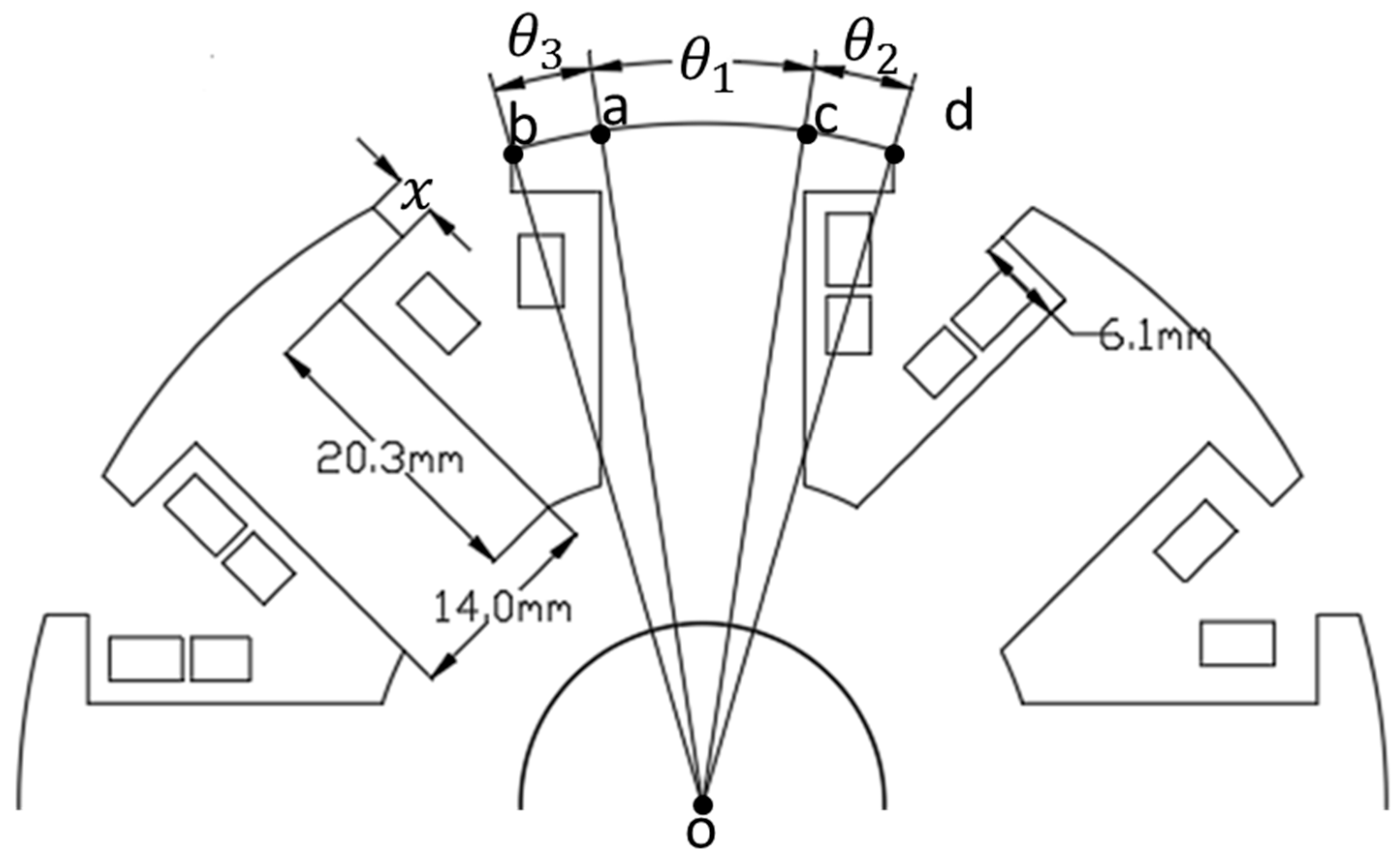
Figure 8 shows the rotor structure with the design variables.
The rotor pole span is given in Equation (1),
where
,
and
are in electrical degrees.
For the optimization of the pole shape, is kept constant to 68 electrical degrees, while and are varied to reduce the torque ripple.
The pole shoe height is given in Equation (2).
where ‘
’ is the pole shoe height in mm.
The objective function for improving the torque and reducing the torque ripple is shown in (3) and the ranges of the design variables are shown in (4).
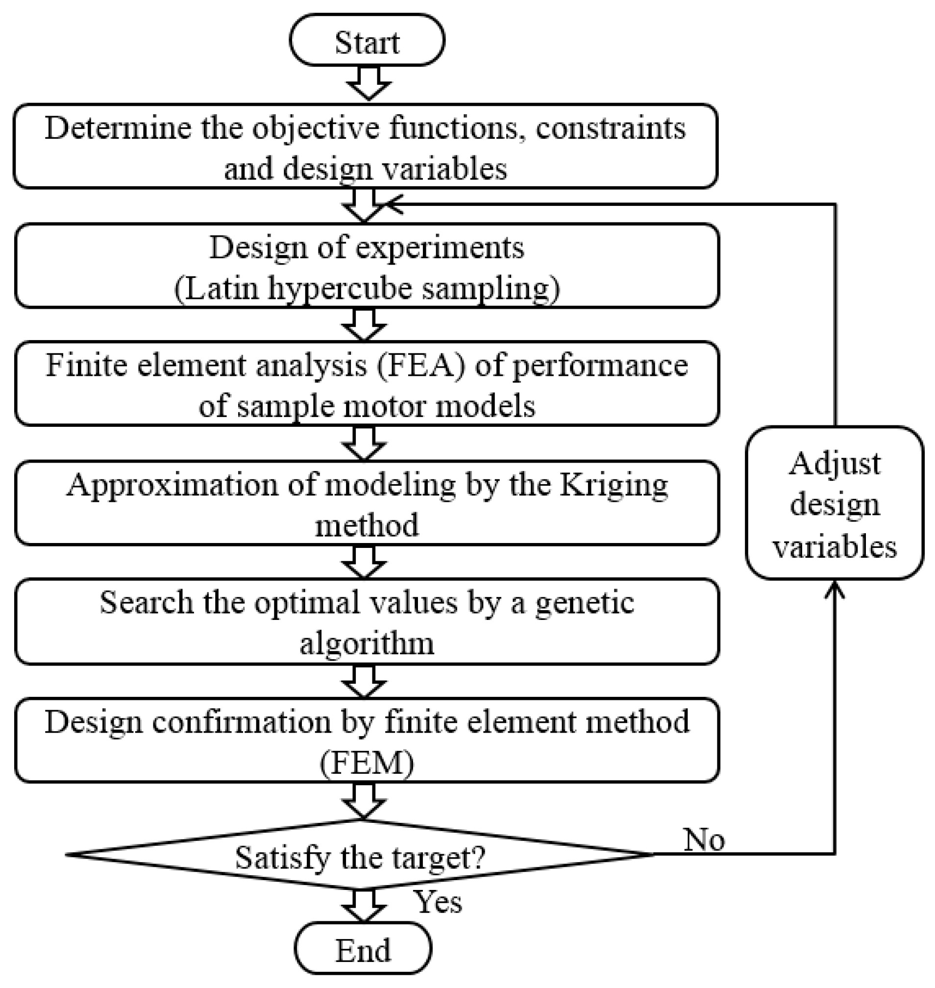
The optimal design process is depicted in
Figure 9. First, the objective functions and then the range of design variables were decided, as given in Equations (3) and (4). Then, the Latin hypercube sampling method was applied to select the sampling points in accordance with the design of experiments process. Finite element analysis (FEA) was used to calculate the output performances for each sample model. The Kriging method was utilized for the approximation modeling. The genetic algorithm evaluates the fitness from the modeling developed by the Kriging model, thus the optimal results were determined by the population analysis using PIAnO software ver. 2018. To obtain the optimal values of design variables, 50% importance weight was set for each of the objective functions. Moreover, to decrease the saturation at the pole shoe wing, the rotor core area was increased at the joining point of the rotor pole body and the pole shoe wing. This modification was made by the machine design experience and with the aid of simulation analysis by ANSYS Maxwell. Finally, the 2-D finite element method (FEM) verified the optimal design results. The optimal model of the rotor pole structure is shown in
Figure 10. Whereas, the optimal design variables are reported in Equation (5).
The flux density distribution of the optimal BL-WRSM model is shown in
Figure 11. It shows that the BL-WRSM is working under the flux density of 2T.
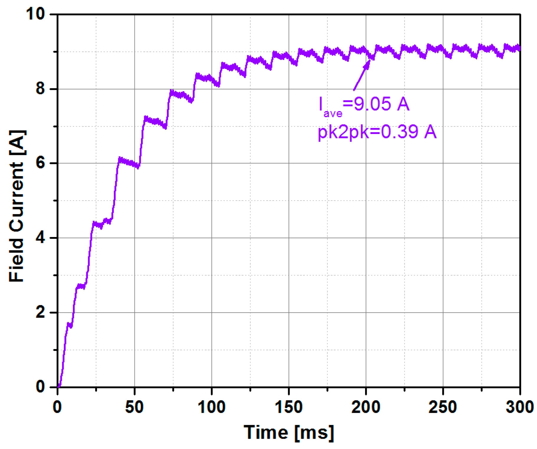
Figure 12 shows the field current of the optimal model. The average value of the field current in the steady state is 9.05 A with the peak-to-peak value of 0.39 A, which results in 4.3% ripples in the field current. The ripple in the field current of optimal model is 3.7% less than the field current ripple of basic model.
Torque of the optimal model of the BL-WRSM is shown in
Figure 13. The optimal model of BL-WRSM achieves the steady state at 200 ms and the average torque observed was 7.28 Nm with a torque ripple of 17.8%. The torque ripple of the optimal model
BL-WRSM is significantly (61.8%) lower than the basic model. However, the torque of the optimal model is reduced by 13.74% as compared to the basic model. This decrease in torque is mainly due to the increase in air gap at the ending edge of the pole shoe. The torque of the optimal model is improved by optimizing the number of turns of the harmonic winding, as discussed in the following section.
3.3. Harmonic Winding Optimization
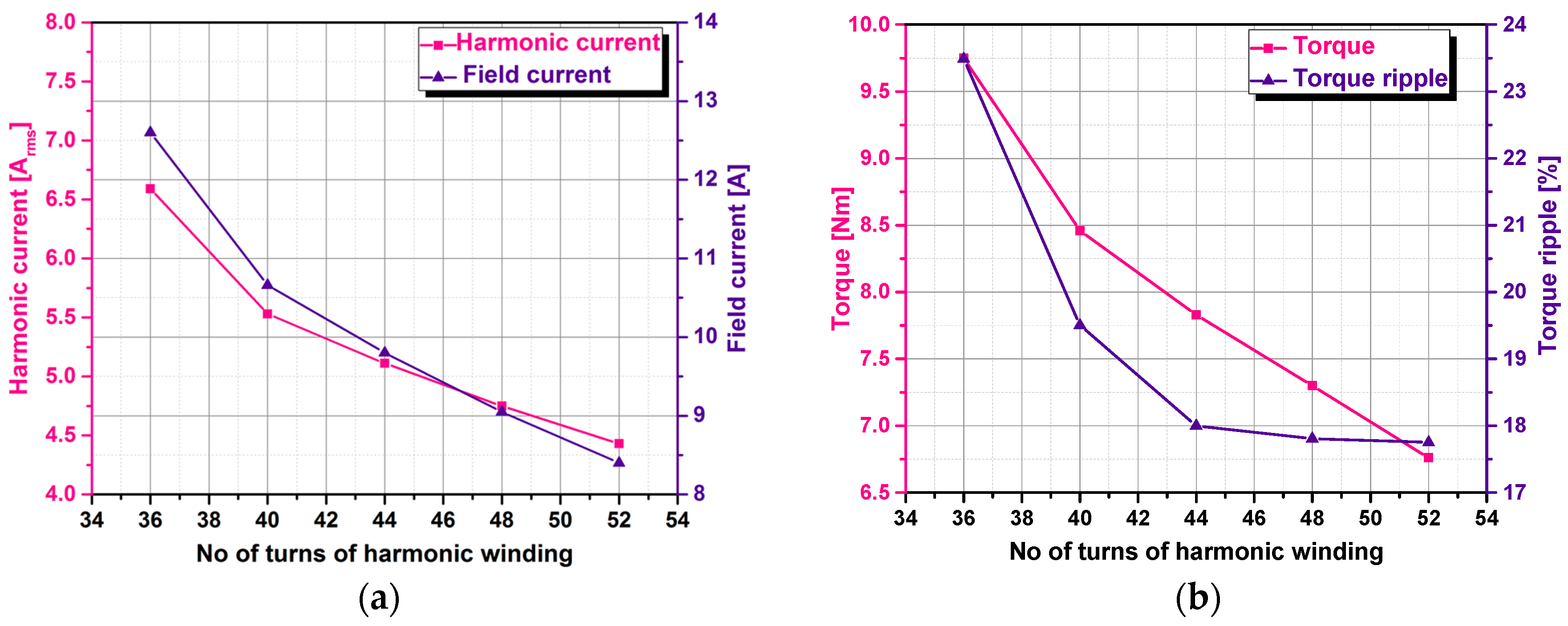
The harmonic winding of the BL-WRSM is optimized to improve the average torque. In the basic model, there are 48 turns (12 turns per pole) of harmonic winding. For the harmonic winding optimization, the number of turns was varied from 36 to 52. The current applied to the stator winding is of fixed value of 4.5 A
rms, which results in the constant magnitude of the subharmonic component of stator MMF. Therefore, with the increase of number of turns of harmonic winding, the induced voltage due to the subharmonic component of stator MMF is increased. However, to maintain the same power due to the subharmonic component on both the stator and rotor side, the current in the harmonic winding is decreased from 6.59 A
rms to 4.43 A
rms. Resultantly, the field current is decreased from 12.60 A to 8.40 A. The effect of variation of the harmonic winding turns on the harmonic and field current are shown in
Figure 14a. Due to this decrease in the field current, the magnetic loading of the machine is decreased, which results in decrease in the machine’s torque.
Figure 14b shows the effect of the variation of the harmonic winding turns on the torque and torque ripple of the machine. To operate the BL-WRSM at about 1 hp, 44 turns for the harmonic winding are selected. The torque in this case is 7.83 Nm with a slightly increased torque ripple of 18%.
Table 2 summarizes the performance comparison obtained by 2-D FEM examination of the basic model and optimal BL-WRSM model. The torque of the optimal model is 7.8% less than the torque of the basic model. This decrease in torque is because of the increased air gap at the edges of the rotor pole shoe. However, the torque ripple in the optimal model is decreased by 61.6% compared to the basic BL-WRSM model. Moreover, the efficiency of both the basic model and optimal model of BL-WRSM are similar.
4. Variable Speed Characteristics of BL-WRSM
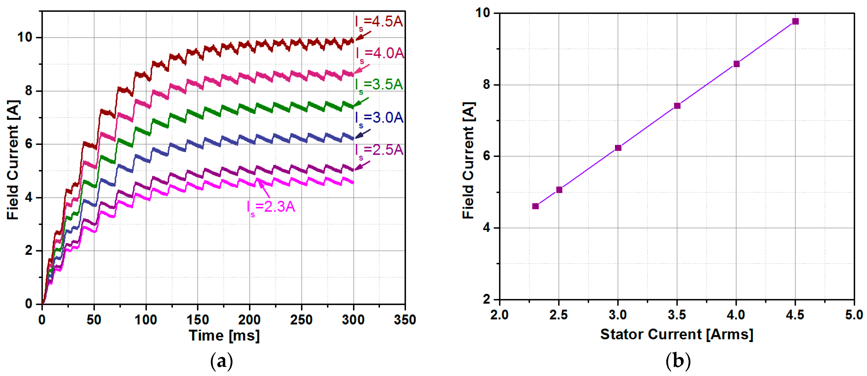
The optimal BL-WRSM model was analyzed for variable speed operation. The brushless operation of the proposed BL-WRSM is achieved by applying the three-phase currents to the stator windings, while the rotor speed has been set constant at different values; consequently, current frequency has been varied accordingly in order to satisfy the synchronism constraint. The input stator current is the only source of external excitation, which is used to excite the field winding of the machine as well as used for producing the output torque. The field current is induced from the harmonic component of stator MMF and depends upon its magnitude as well as its frequency. When the machine operates below its rated speed, the frequency of the harmonic component decreases that results in a decrease in its field current and the torque developed by the machine reduces. Therefore, constant torque region for the brushless synchronous machine cannot be achieved. For the machine operation beyond its rated speed, that is the constant power region in a conventional drive system, the harmonic component is reduced by controlling the stator current to reduce the torque of the machine. It implies that the developed brushless WRSM is only suitable for its rated speed or higher speeds and cannot be applicable for low speed applications. The stator current of the machine is varied from the rated current of 4.5 A
rms to 2.3 A
rms. This decrease in the stator current results in a decrease of the field current to allow for the increase in the machine’s speed, as shown in
Figure 15a.
Figure 15b shows the change of the field current rms value with respect to change in the stator current.
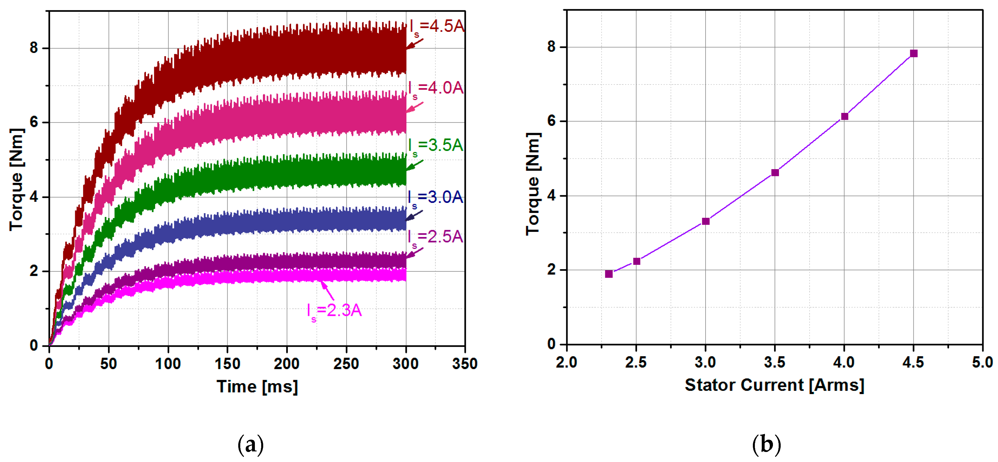
Due to the decrease in the stator current and field current, the electric and magnetic loading of the machine will decrease, which results in the decrease of the torque.
Figure 16a shows the variation of the machine torque due to change in the stator current. The torque is decreased from the rated value of 7.83 Nm to 1.9 Nm.
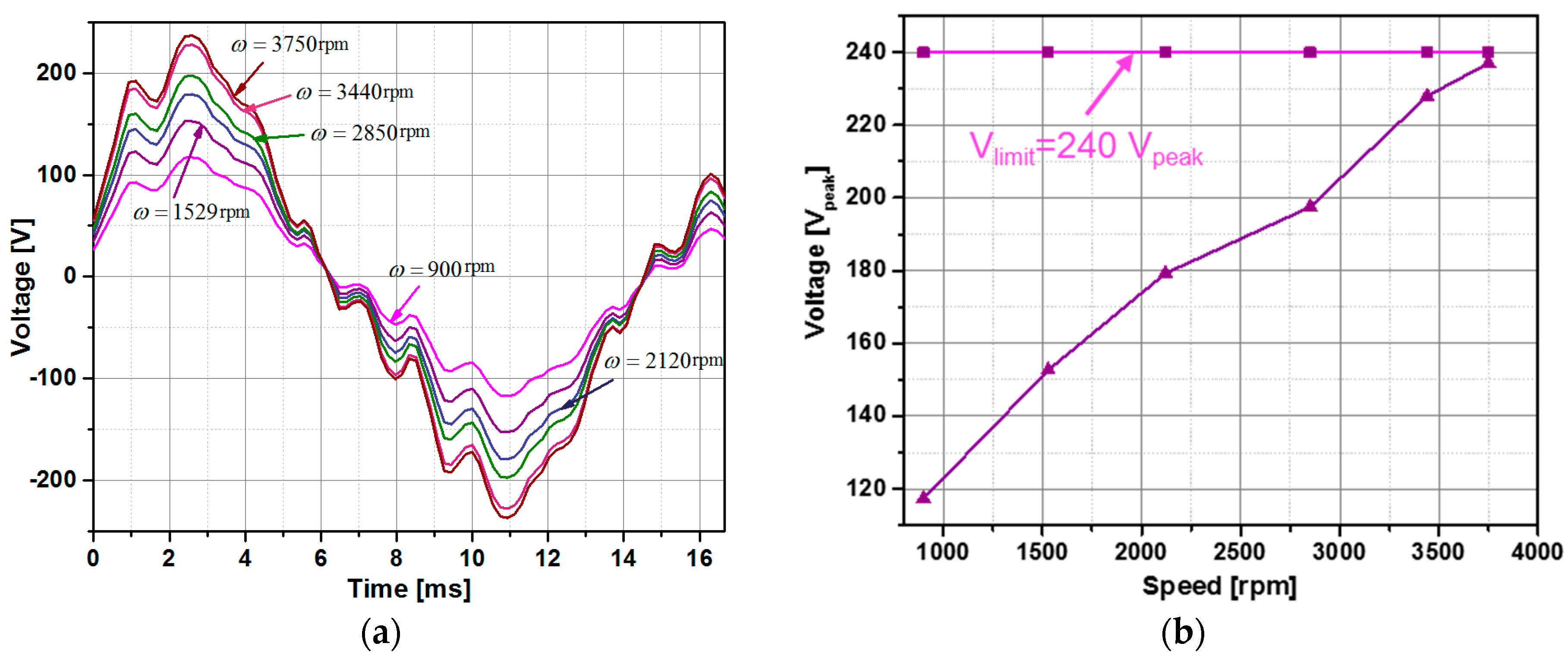
Figure 16b shows the change of the average value of torque with respect to change in stator current. To operate the BL-WRSM at the rated power of 746 watts, the speed is varied from the rated speed of 900 rpm to 3750 rpm. The terminal voltages of the machine for the differed operating speeds to achieve the required torque are given in
Figure 17a. It can be observed that the peak value of the voltage of the machine remains under the inverter voltage limit of 240 V
peak. The variation of the voltages with the change in speed of operation is given in
Figure 17b, which depicts the terminal voltage of the machine under loaded conditions instead of only the back EMF of the machine. The results given from
Figure 16,
Figure 17 and
Figure 18 shows the proposed brushless machine can achieve a wide speed range of 4.17 times the rated speed.
5. Prototype and Experimental Verification
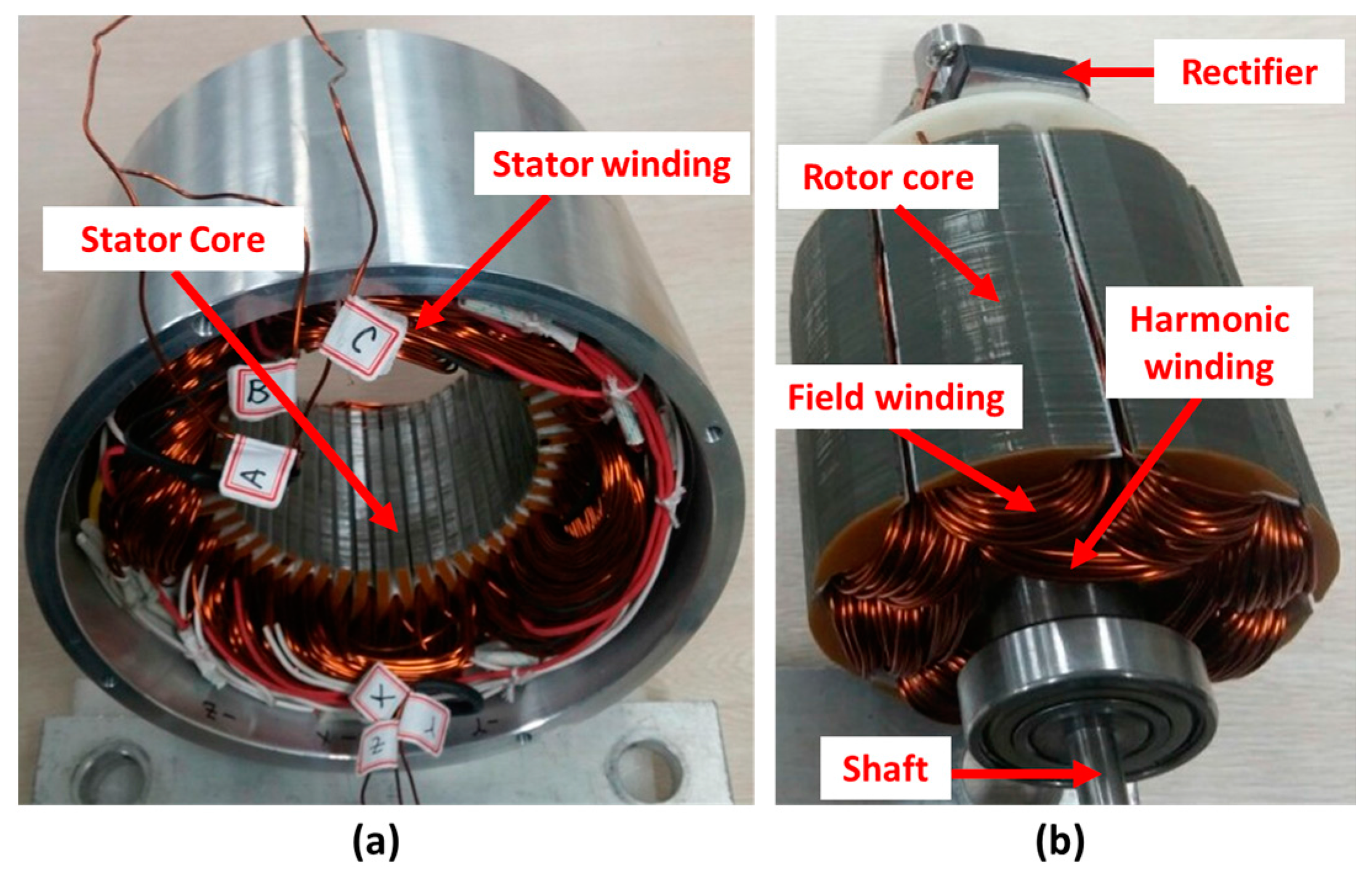
In order to validate the aforementioned analysis, a BL-WRSM prototype machine has been built as shown in
Figure 18, and its major design parameters are listed in
Table 3.
Figure 18a shows the stator for the BL-WRSM with eight-pole, 48-slot double layer distributed winding.
Figure 18b shows the rotor of the BL-WRSM with field windings and harmonic windings. Both the rotor windings are connected in parallel to each other through the diode bridge rectifier.
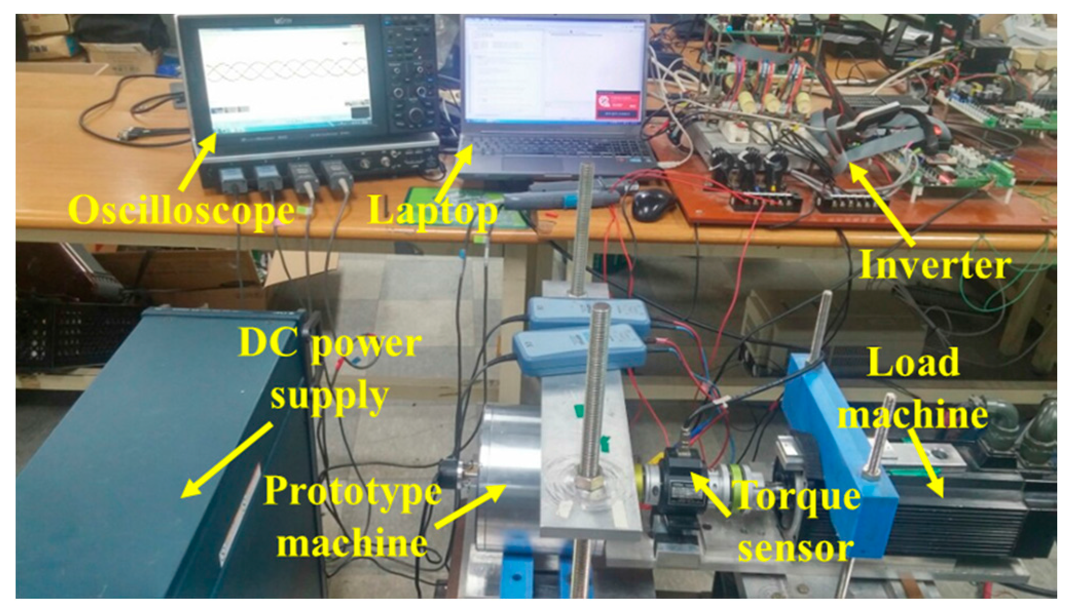
Figure 19 shows the complete experimental setup with a prototype machine connected to the load machine, digital signal processing (DSP) board, oscilloscopes and DC power supply and the torque sensor used for torque measurement.
In order to apply the stator current with proper phase angle, the initial position estimation was made by initially exciting the field winding through an external power supply using an external switch. The shaft encoder was fixed to indicate the rotor initial position and the external switch was removed to directly connect the field winding with harmonic winding via rectifier. Moreover, the BL-WRSM is not a self-start machine and an external source was used to initially start the machine. Once the machine achieved its rated speed of 900 rpm, the load was applied to its rated value that resulted in 4.5 Arms stator current. The stator current was controlled using close loop current controller implemented in the synchronous frame of reference. The outer speed control was implemented to achieve the desired speed of the machine [
23]. The three-phase current supplied to the stator winding is shown in
Figure 20.
The measured torque for the prototype of the optimal BL-WRSM model is shown in
Figure 21. The prototype machine exhibits 7.49 Nm torque compared with the 7.83 Nm obtained by the FEA. A torque ripple of about 18.6% was observed in the prototype.
The performance of the prototype machine as compared to the optimal model is shown in
Table 4. The efficiency of the BL-WRSM prototype was measured by considering the copper loss and core loss of the machine. The prototype machine exhibits the efficiency of 78.48% as compared to 79.22% of the optimal model analyzed by 2-D FEM.


