Active Stabilization Control of Multi-Terminal AC/DC Hybrid System Based on Flexible Low-Voltage DC Power Distribution

1
Institute of Electrical Engineering, Chinese Academy of Sciences, No. 6 Beiertiao, Zhongguancun, Beijing 100190, China
2
The School of Electronic, Electrical and Communication Engineering (EECE), University of Chinese Academy of Sciences, No. 19(A) Yuquan Road, Shijingshan District, Beijing 100049, China
*
Author to whom correspondence should be addressed.
Energies 2018, 11(3), 502; https://doi.org/10.3390/en11030502
Submission received: 28 December 2017
/
Revised: 22 January 2018
/
Accepted: 31 January 2018
/
Published: 27 February 2018
(This article belongs to the Special Issue DC Systems)
Abstract
:Multi-terminal AC/DC interconnection will be an important form of future distribution networks. In a multi-terminal AC/DC system, if scheduled power for the AC/DC converter exceeds limits this may result in instability of the DC network. In order to overcome these limitations and avoid an unstable situation during coordinated control, this paper proposes a general active stabilization method for a low-voltage multi-terminal AC/DC hybrid system. First, the typical coordinated control modes for a hybrid system are analyzed. Second, a multi-level active stabilization controller, using the Lyapunov method, is introduced, and a feedback law allowing large signal stability is proposed. Finally, a system simulation model is further established, and the proposed active stabilization method is tested and verified. Study results show that only low stabilizing power with a slight influence on the DC network dynamic can improve the system’s stability and ensure stable system voltage.
1. Introduction
With the rapid development and widespread application of new energy sources, new materials, and power electronics technology, users’ requirements in terms of power quality, reliability, and operational efficiency are increasing constantly and, as a result, the existing AC distribution network is facing considerable challenges in many areas, such as the diversification of electricity demand, large-scale distributed-generation access, the complex coordinated control of power flow, and so on. On the one hand, the type and quantity of electrical equipment in the distribution network has changed, and a large number of electric vehicles (EV), energy-storage systems, LED lights, and other DC devices are being widely used [1,2,3]. On the other hand, if distributed generation, such as the photovoltaic (PV) fuel cell, adopts the DC grid-connected interface, some conversion sections can be reduced, and the overall operational efficiency can be improved [4]. Consequently, these trends make the development of DC-distribution technology inevitable.
It is noteworthy that AC equipment is still the main form of power consumption in the distribution network, and that the access of DC equipment will lead to the long-term coexistence of AC and DC loads. Therefore, an AC/DC hybrid system will become an important form of power distribution in the future [5,6,7,8,9]. In the United States, the Center for Power Electronics Systems (CPES) of Virginia Polytechnic Institute and State University has built a hybrid distribution system based on AC/DC stratified connections [10]. The University of North Carolina has presented a future renewable-electric energy-delivery and management system (FREEDM), with a 400 V DC network and a 120 V AC network, which connects to the external power grid through an intelligent energy management (IEM) interface [11]. Moreover, the micro-grid of Osaka University in Japan [12] and the European universal and flexible power-management system (UNIFLEX) [13] have also put forward AC/DC power-distribution systems. Coordinated control is an important foundation for the stable operation of a multi-terminal AC/DC hybrid system [14]. How to achieve the coordinated operation of various types of distributed generation, loads, energy storage, and AC/DC converters has become one of the technological challenges of AC/DC hybrid system development. To date, there have been some achievements in the field of coordinated control in a multi-terminal AC/DC hybrid system. In [15], coordination-control algorithms in a hybrid AC/DC micro-grid for converters, such as a PV panel, wind-turbine generator (WTG) with a double-fed induction generator (DFIG), and battery, are studied, and have been modeled and verified using Simulink in MATLAB. In [16], a hybrid structure for an AC grid-connected micro-grid, with a DC connection based on back-to-back (B2B) converters, is studied, a control scheme for the utility-interfacing voltage-source converter (VSC) and DC micro sources is proposed, and different operating scenarios, even faults inside or outside the micro-grid, are also investigated. In [17], typical operation modes for low-voltage (LV) AC/DC micro-grids are proposed, and a coordination-control method of utility-interfacing VSC, storage energy, PV, and direct-driven WTG with a permanent magnet synchronous generator (PMSG) under each operation mode, are put forward. In [18], an improved virtual-impedance control method is proposed for bi-directional power converters in hybrid AC/DC microgrids operated in island mode, in order to reduce the circulating current and for accurate power-sharing. In [19], a new droop control scheme is investigated for a hybrid microgrid formed by multiple AC and DC sub-grids, in order to ensure active power-sharing and the autonomous operation of the hybrid microgrid. In [20], the power-sharing control issues in hybrid AC/DC microgrids are discussed, the drawbacks of conventional voltage droop methods are described, and a new frequency droop-based strategy is proposed to share power in hybrid microgrids.
This research mainly takes the DC bus voltage signal (DBS) as the judgment criterion in order to propose a hierarchical or coordinated control strategy based on different operating system modes, and adjusts each converter to ensure power balance under various conditions. However, this method can only make DC voltage maintain the ideal reference value when the utility grid is normal; in other cases, DC voltage will deviate from the ideal reference point, which obeys a differential regulation. Nevertheless, a DC network contains a lot of constant power load (CPL) in practical applications, and CPL has negative impedance characteristics. Therefore, DC voltage deviating from the ideal reference point may aggravate DC-voltage fluctuations, and even lead to the collapse of the whole system [21,22]. Tools allowing large signal-stability analysis of a DC-power system with CPLs, such as the Takagi-Sugeno (TS) multi-modeling, block-diagonalized quadratic Lyapunov function, Brayton-Moser’s mixed potential function, and reverse-trajectory tracking, have been introduced [22], and a general active control method is proposed for multi-CPL DC power networks in order to ensure the system is stabilized at an operating point, which would otherwise be unstable [23].
However, the above studies mainly focus on AC/DC systems with low power and multi-loads. There is still a lack of effective coordinated control methods for a multi-terminal AC/DC hybrid system with multi-sources, high power and higher voltage. Using a multi-terminal AC/DC hybrid system based on flexible LV DC power distribution, this paper establishes an electrical equivalent model and the state-space model required for coordinated control. An active stabilization-control method using the Lyapunov theory is then proposed, and feedback laws are designed to ensure system global stability, a wide operational boundary with lower control cost, stable voltage of the DC network, and the normal operation of each piece of equipment in some operating conditions that would otherwise be unstable.
This paper is structured as follows: Section 2 outlines the typical structure and coordinated control mode of the LV multi-terminal AC/DC hybrid system. Section 3 carries out system-stability analysis in order to study the stable boundary. Section 4 proposes the multi-level active stabilization control method. Section 5 shows the corresponding simulation results and analysis. Conclusions are drawn in Section 6.
2. Coordinated Control Mode of Low-Voltage (LV) Multi-Terminal AC/DC Hybrid System
2.1. System Structure
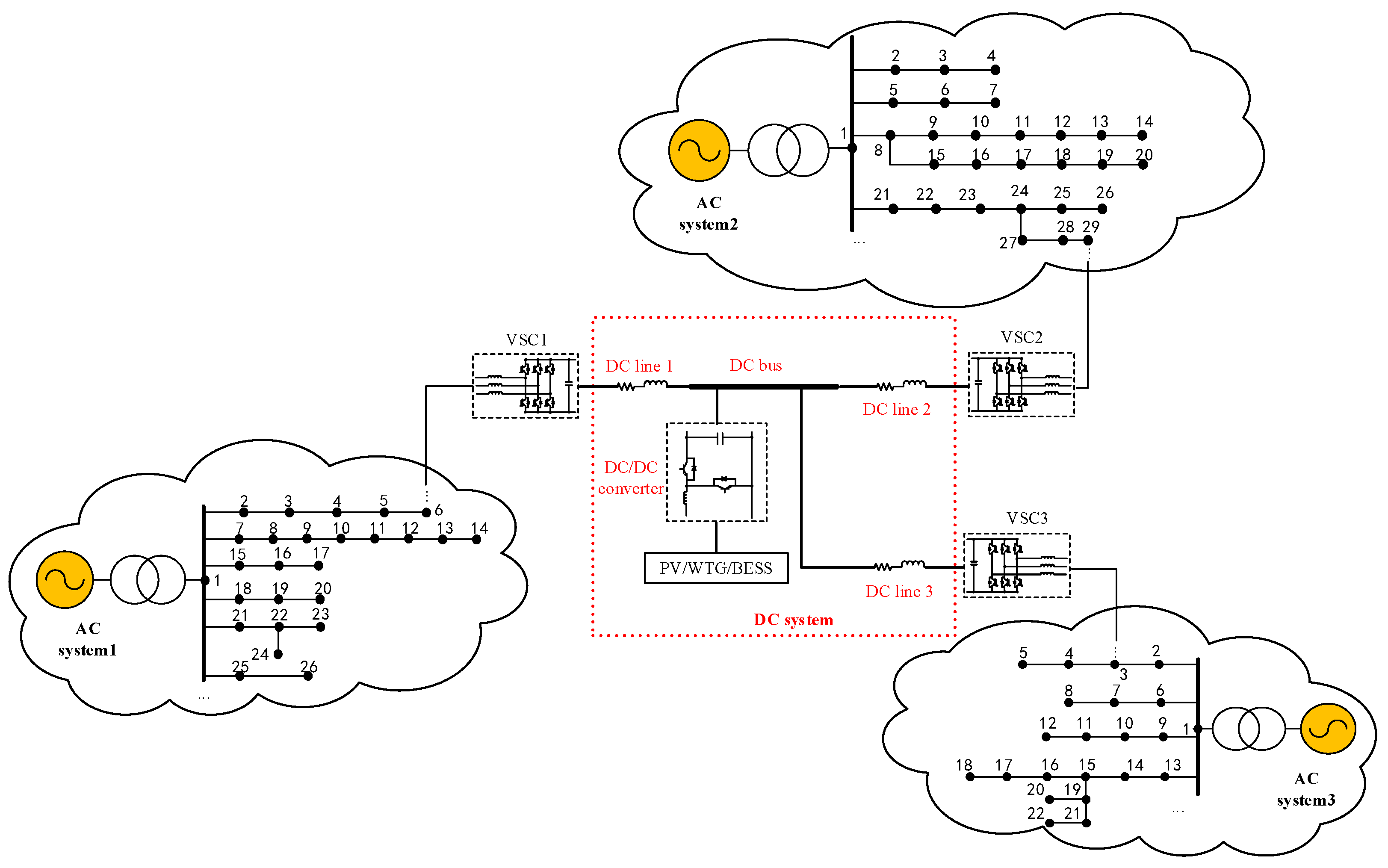
The typical structure of a LV multi-terminal AC/DC hybrid system is shown in Figure 1. The utility-interfacing VSC is the interconnection interface between the AC and DC systems. The AC side of each utility-interfacing VSC is connected to some AC line or AC node located in the corresponding AC system, and the DC side of each utility-interfacing VSC is connected to the DC system. It is noteworthy that AC systems do not exist with interconnections directly between each other, and each AC system has the independent voltage and frequency support provided by its internal utility grid, respectively. The AC system can absorb power from the DC system or inject power into the DC system through the utility-interfacing VSC, according to the power instructions from the dispatch agency. Based on the power exchange between each AC and DC system, load-balancing and power-flow optimization among multiple AC systems can be achieved.
The DC sides of the VSC1, VSC2, and VSC3 are connected to each other through the DC system, which can build the multi-terminal interconnection structure. A DC device, such as a PV, WTG, EV, or battery energy-storage system (BESS) is usually integrated into the DC system through the DC/DC converter.
2.2. Coordinated Control Mode
The utility-interfacing VSC usually adopts Udc and Q control, P and Q control and droop control, and the corresponding detailed control strategies are shown in Figure 2.
Take VSC1 shown in Figure 1 as an example; its P and Q control is formed by the outer power loop and inner-currents loop to realize active/reactive power-tracking scheduling, where P and Q, respectively, represent the actual active power and reactive power of the VSC; Pref and Qref respectively represent the reference active power and reactive power of the VSC (subscript ref indicates the reference of variables in this article); vabc represents the actual three-phase AC voltages of the VSC; and iabc represents the actual three-phase AC currents of the VSC. Udc and Q control is formed by the outer DC voltage loop and inner-currents loop, and is responsible for providing constant voltage for the DC network, where Udc,ref and Udc respectively represent the reference and actual voltage of the DC network; idref and iqref, respectively, represent the d-q axis reference of three-phase AC currents of the VSC (subscripts d, q respectively indicate the d axis reference and q axis reference of variables in this article); and id and iq respectively represent the d-q axis value of iabc. Droop control is formed by the outer DC voltage droop loop and inner-currents loop, and is responsible for controlling the voltage for the DC network while sharing loads.
Based on the aforementioned control strategies, the coordinated control of the LV multi-terminal AC/DC hybrid system can be divided into master–slave mode or peer-to-peer mode. For the master–slave mode, one VSC adopts the Udc and Q control to be master VSC in order to provide stable voltage of the DC network; meanwhile, the other VSCs adopt the P and Q control to be slave VSCs in order to adjust active/reactive power, accepting and tracking the power-scheduling command, respectively. For the peer-to-peer mode, each VSC adopts droop control in order to provide voltage support and DC load-sharing collectively.
This paper mainly studies the master-slave mode, so the voltage of the DC network is controlled by one master VSC, and the other slave VSCs track the power-scheduling command, avoiding voltage regulation by multiple VSCs, and the coupling between individual controls.
3. System Stability Analysis
3.1. Equivalent Structure
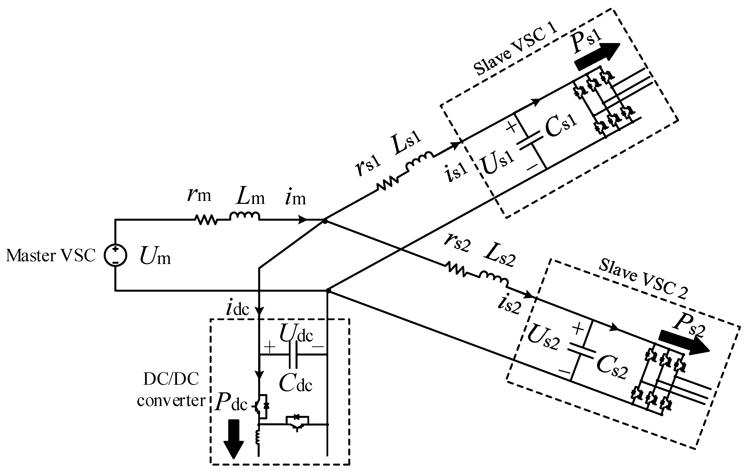
At present, the master-slave mode of LV multi-terminal AC/DC hybrid systems is more common in practical applications. Take Figure 1 as an example; under this mode, if VSC1 is the master VSC to provide constant DC voltage, and VSC2 and VSC3 are the slave VSCs accepting power scheduling, assuming that the power loss of VSC2, VSC3 and the DC/DC converter can be neglected, the system equivalent structure can be presented in Figure 3. The DC line (rm, Lm) connects the master VSC and DC bus; DC lines (rs1, Ls1 and rs2, Ls2) connect each slave VSC and the DC bus.
3.2. Stable Operation Boundary of Voltage-Source Converter (VSC)
The system shown in Figure 3 can be modelled as follows:
Subscripts m, s1, s2, and dc respectively indicate the variables of master VSC, slave VSC1, slave VSC2, and DC/DC converter in this article. Um and im, respectively, represent the DC voltage and current of the master VSC. Us1, is1, Cs1, and Ps1, respectively, represent the DC voltage, current, capacitor and actual active power of the slave VSC1. Us2, is2, Cs2, and Ps2, respectively, represent the DC voltage, current, capacitor, and actual active power of the slave VSC2. idc, Cdc, and Pdc, respectively, represent the DC current, capacitor, and actual active power of the DC/DC converter.
Slave VSC1, slave VSC2, and the DC/DC converter have operational boundary constraints between each other, and cannot be adjusted arbitrarily. The system will remain stable when they cooperate with each other in a stable region; otherwise, it will be unstable. The stable operational boundaries of slave VSC1 and slave VSC2 under three conditions (Pdc = −30 kW, Pdc = 0 kW, Pdc = 30 kW) are shown in Figure 4, based on Equation (1) with necessary parameters shown in Table 1 (Pm,rated, Ps1,rated, Ps2,rated, and Pdc,rated represent the rated power of the master VCS, slave VSC1, slave VSC2, and DC/DC converter, respectively).
In Figure 4a, the DC/DC converter works as a power supply and outputs active power with Pdc = −30 kW. If Ps2 changes, the stable operation boundary of slave VSC1, represented as Ps1.stab, varies accordingly, and the maximum stable operation boundary of slave VSC1, represented as Ps1.stabmax is obtained (Ps1.stabmax ≈ 95 kW) when Ps2 = 0; at the same time, if Ps1 changes, the stable operation boundary of slave VSC2, represented as Ps2.stab, varies accordingly, and the maximum stable operation boundary of slave VSC2, represented as Ps2.stabmax, is obtained (Ps2.stabmax ≈ 270 kW) when Ps1 = 0.
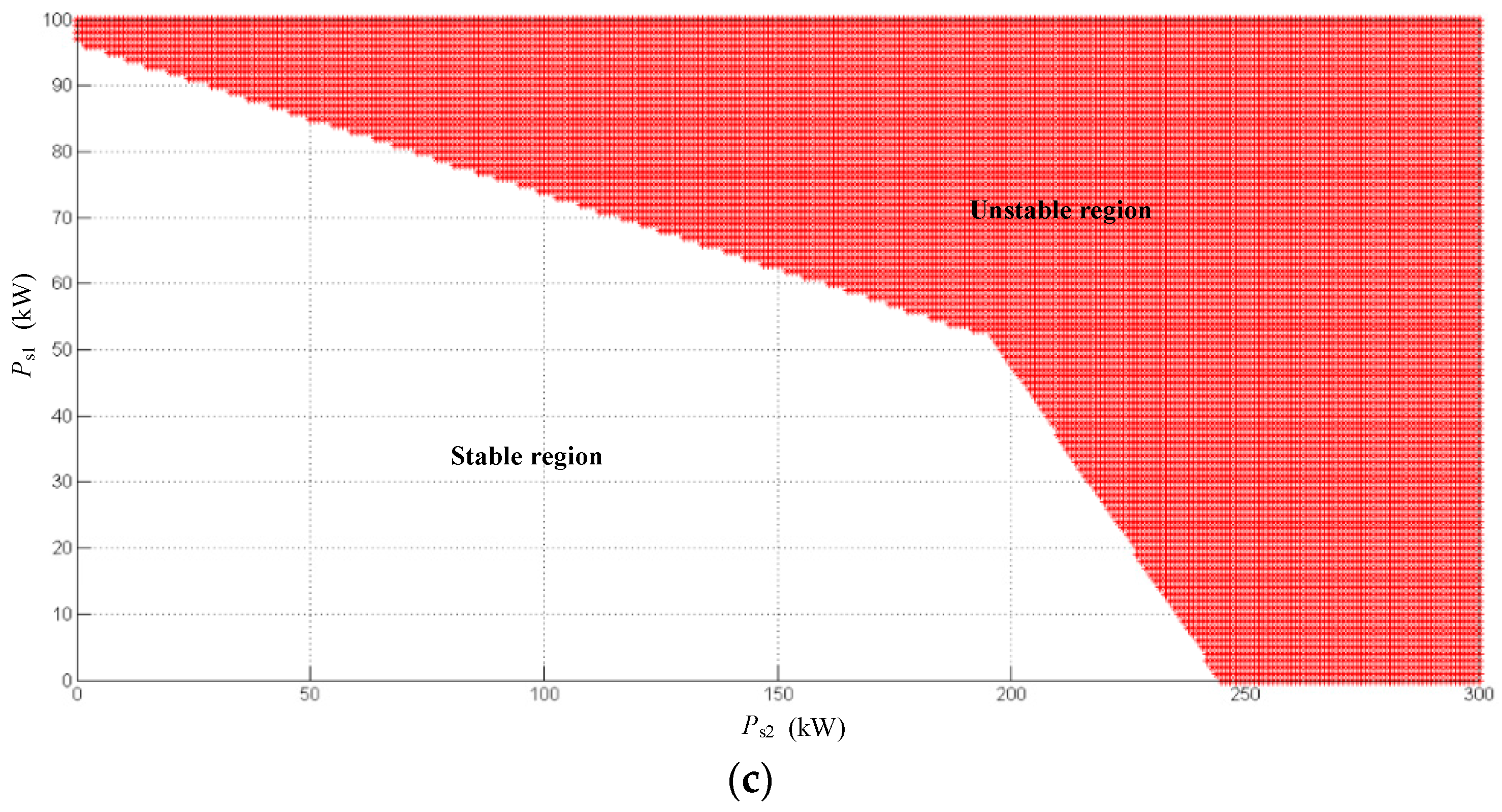
When the output power of the DC/DC converter gradually reduces to 0 kW, Figure 4b shows that Ps1.stabmax has no obvious change and, meanwhile, Ps2.stabmax is decreased to about 260 kW. When the DC/DC converter is used as a load to absorb power with Pdc = 30 kW, Figure 4c shows that Ps1.stabmax still has no significant change, while Ps2.stabmax is decreased to about 245 kW. In summary, for a DC/DC converter, the output power decreases when it is used as a power supply, or absorption power increases as load, Ps1.stabmax, is affected less, but Ps2.stabmax will be decreased, obviously.
3.3. Instability Analysis
In order to research system stability, a simulation model of the LV multi-terminal AC/DC hybrid system depicted in Figure 3 is established by MATLAB/Simulink (R2014a, The MathWorks, Inc., Natick, MA, USA), and the specific simulation parameters are shown in Table 1. The operational condition with relatively less stability margin in Section 3.2 is selected to show the influence of the operation point change on system stability. In the simulation model, the master VCS adopts Udc and Q control with Um = 800 V; slave VSC1 and slave VSC2, respectively, adopt P and Q control with Ps1 = 50 kW and Ps2 = 50 kW; and the DC/DC converter is used as a load with Pdc = 30 kW. The rated line-to-line voltage and rated frequency of AC system 1, AC system 2, and AC system 3 are 380 V and 50 Hz, respectively.
As shown in Figure 4c, the operation point (Ps1 = 50 kW, Ps2 = 50 kW) is in the stable region; the operation point (Ps1 = 80 kW, Ps2 = 50 kW) is also in the stable region, but close to unstable region; and the operation point (Ps1 = 90 kW, Ps2 = 50 kW) is already in the unstable region.
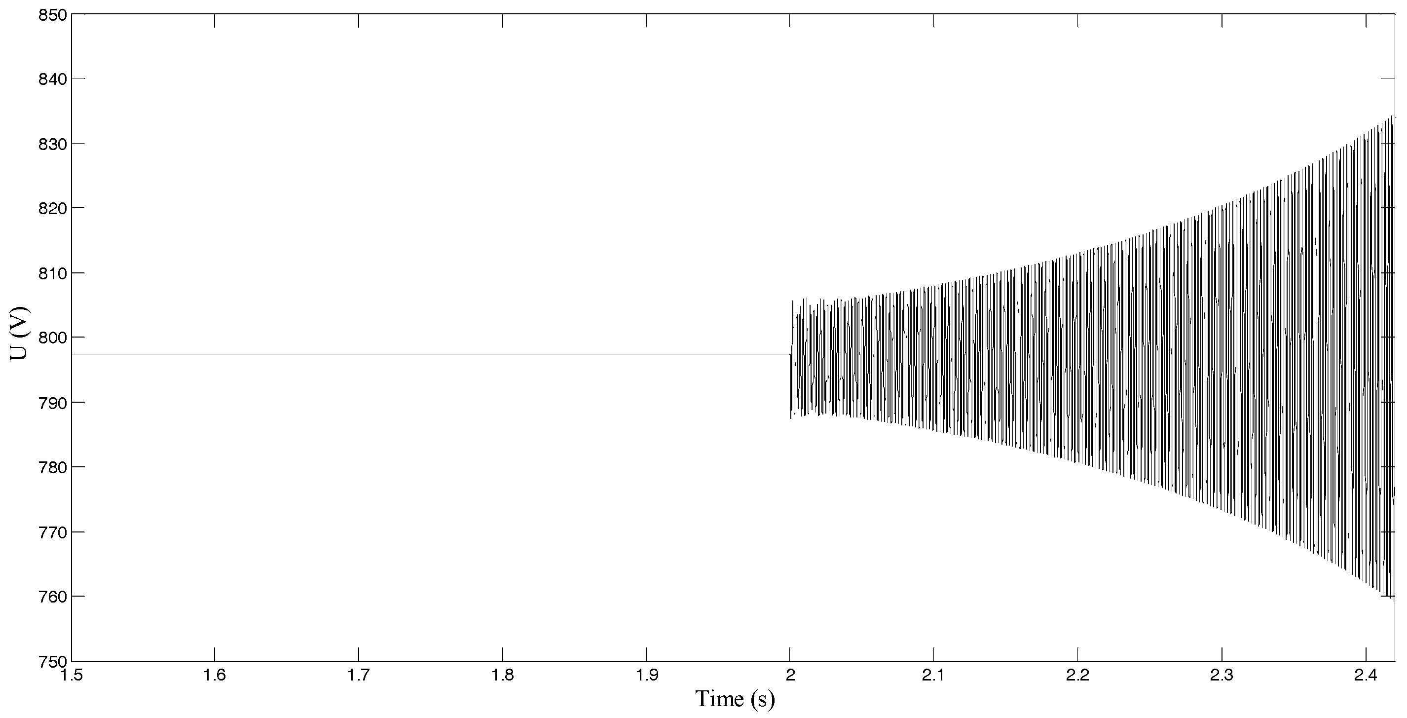
Figure 5 describes the simulation waveform of Udc when the operation point (Ps1 = 50 kW, Ps2 = 50 kW) is changed to (Ps1 = 80 kW, Ps2 = 50 kW) and (Ps1 = 90 kW, Ps2 = 50 kW) at t = 2 s. As shown in Figure 5a, Udc has a short-term and small amplitude oscillations when Ps1 changes, but it can quickly restore a steady state. As shown in Figure 5b, when Ps1 is changed to 90 kW, Udc cannot be restored to a stable voltage after the short-time damping oscillation, and there is then a divergent oscillation until instability of the voltage.
From the results shown in Figure 5, Ps1, Ps2, and Pdc have operation boundary constraints between each other, and in the process of their coordinated control, when the transmitted power of any one exceeds the corresponding stable operation boundary, they will enter the unstable region, and DC voltage could then be unstable, further affecting the stability of the whole system. This also means that the transmitted power of each VSC in an LV multi-terminal AC/DC hybrid system will be limited under operation boundary constraints, and a stability problem must be considered in order to determine the power limitations of VSCs so as to avoid unstable control, which may cause operational failure or damage, and may even overreach these limitations.
4. Active Stabilization Control of LV Multi-Terminal AC/DC Hybrid System
4.1. Stabilization Modeling
The state variables in Equation (1) can be expressed as:
where x = [im, is1, is2, Udc, Us1, Us2]T; superscript * indicates the current value of each variable; superscript o indicates the steady-state value of each variable before a change or disturbance; indicates the variation of each variable. Considering the new state variable vector given by Equation (2), Equation (1) can be expressed by Equation (3).
Then, the system represented in (3) can be modeled by the linear model of Equation (4):
where u = [udc, us1, us2]T; and udc, us1, and us2, respectively, represent the input of , , and . The Lyapunov equation can be represented as Equation (5) [24]:
where P and Q are positive-definite symmetric matrices, and P is a solution of the Lyapunov equation. The feedback law for active stabilization control is designed as follows:
where u′ = [udc,fb, us1,fb, us2,fb]T; and udc,fb, us1,fb, and us2,fb, respectively, represent the feedback of , , and .
PA + ATP + Q = 0
Proof of Theorem 1.
The Lyapunov equation is represented as:
therefore,
Since P is a symmetric matrix, so:
As u is chosen as:
So:
u′ = −BTPx
It is well know that −2PBBTP represents negative-definite matrices because BBT and PP are both positive-definite matrices, and PA + ATP < 0 from (5), therefore:
ATP + PA − 2PBBTP < 0
Thus:
when u′ = −BTPx. It can be seen from this proof that u′ is the state feedback law which can prove the global stability of a LV multi-terminal AC/DC hybrid system. ☐
4.2. Active Stabilization Control Block
In order to stabilize the LV multi-terminal AC/DC hybrid system, the active stabilization-control method is proposed based on Equations (2)–(6), and its main purpose is to implement additional damping control on the existing coordinated control system. Active stabilization control can generate the active stabilization current for each control object, such as slave VSCs, according to their power-scheduling commands, and then the current for any control object will be correspondingly attached to its existing control strategy, in order to ensure system stability. Active stabilization currents can be expressed by Equation (14):
where idc,active, is1,active, and is2,active, respectively, represent the active stabilization current for the DC/DC converter, slave VSC1, and slave VSC2.
The active stabilization control block is shown in Figure 6, which is divided into the system global active stabilizer and the local controller of each control object like the DC/DC converter and slave VSCs. The system’s global active stabilizers are responsible for analyzing the acquired operation data of the LV multi-terminal AC/DC hybrid system, including the voltages, currents, and power-scheduling commands, based on data collection. Then udc, us1, and us2 in Equation (4) can be obtained with the stabilization model established in Section 4.1, and udc,fb, us1,fb, and us2,fb can be calculated by Equations (5) and (6). After that, idc,active, is1,active, and is2,active can be generated and sent to each local controller.
Active stabilization control based on the Lyapunov method is used to achieve additional damping control, which means that the local controller of any control object, like the DC/DC converter and slave VSCs, does not need to change its existing controller structure, strategy, and parameters, and that it is only necessary to superimpose the active stabilization current, such as idc,active, is1,active, and is2,active, generated by the system global active stabilizer on the corresponding received power-scheduling command of the existing controller of the DC/DC converter and slave VSCs in order to realize active stabilization control.
The local controllers need no communication between each other, and each local controller communicates with the system’s global active stabilizer to accept the active stabilization current generated by the latter (when the power of a DC/DC converter is controllable, such as the grid-connected interface of a BESS or EV, the received idc,active can also be added to its power dispatching; otherwise, the DC/DC converter does not execute active stabilization control).
4.3. Stable Operation Boundary of VSC after Implementation of Active Stabilization Control
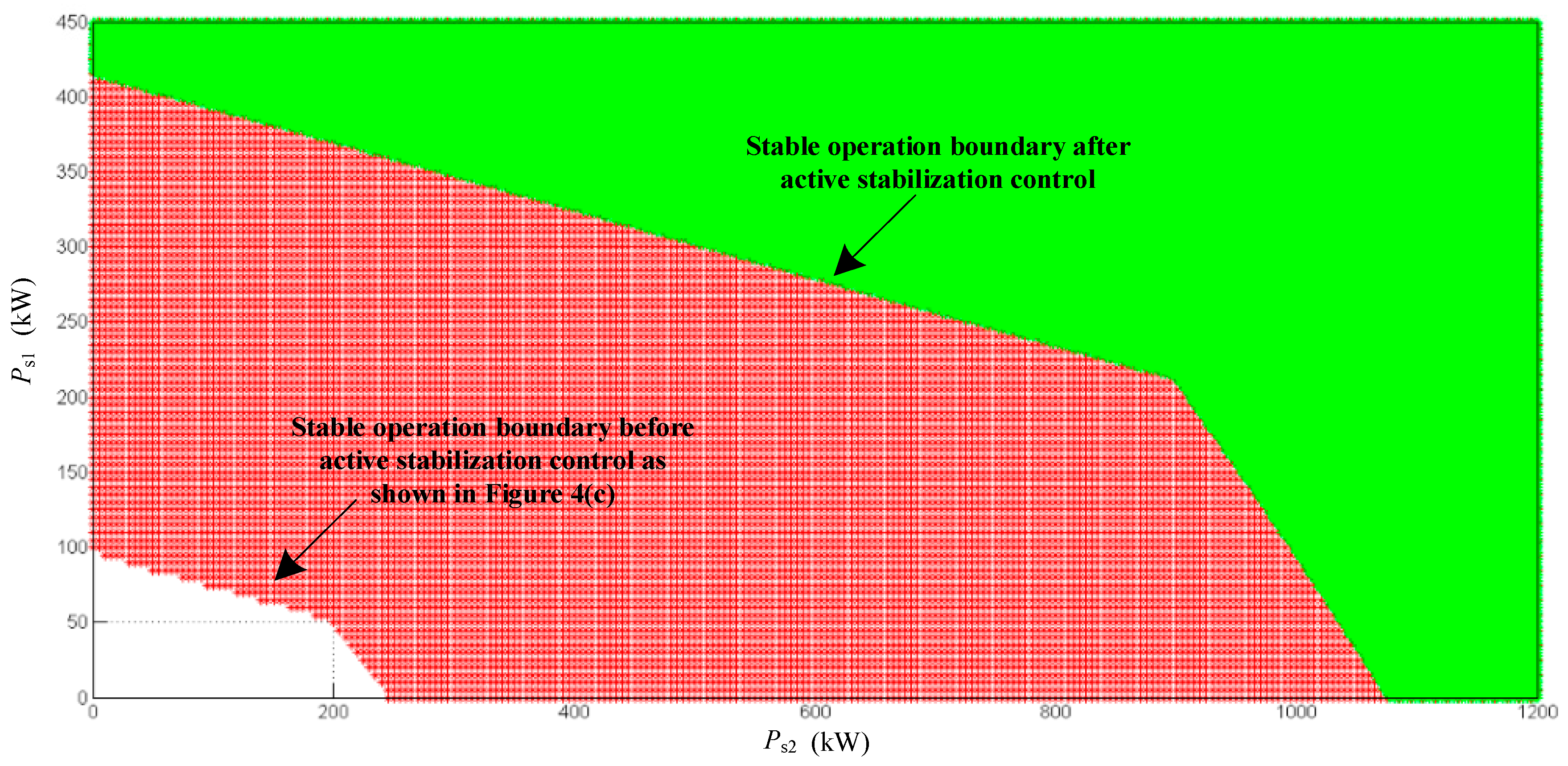
Figure 7 describes the stable operation boundary after implementation of active stabilization control. The new stable operation boundary after implementation of active stabilization control can be significantly improved over the original boundary before the implementation of active stabilization control. Compared with Figure 4c, the stable operation boundary of slave VSC1 and slave VSC2 is obviously expanded, and Ps1.stabmax is increased to about 415 kW while Ps2.stabmax is close to 1075 kW. The higher stable operation boundary means that the power-regulation range for the VSC is wider. Thus, the active stabilization control proposed in this paper can greatly expand the system operation boundary, and change the original power limit of the VSC to enable stable system operation with a higher transmitted power of each VSC.
5. Simulation and Verification
5.1. Active Stabilization Control of the Multi-Terminal VSC and the DC/DC Converter
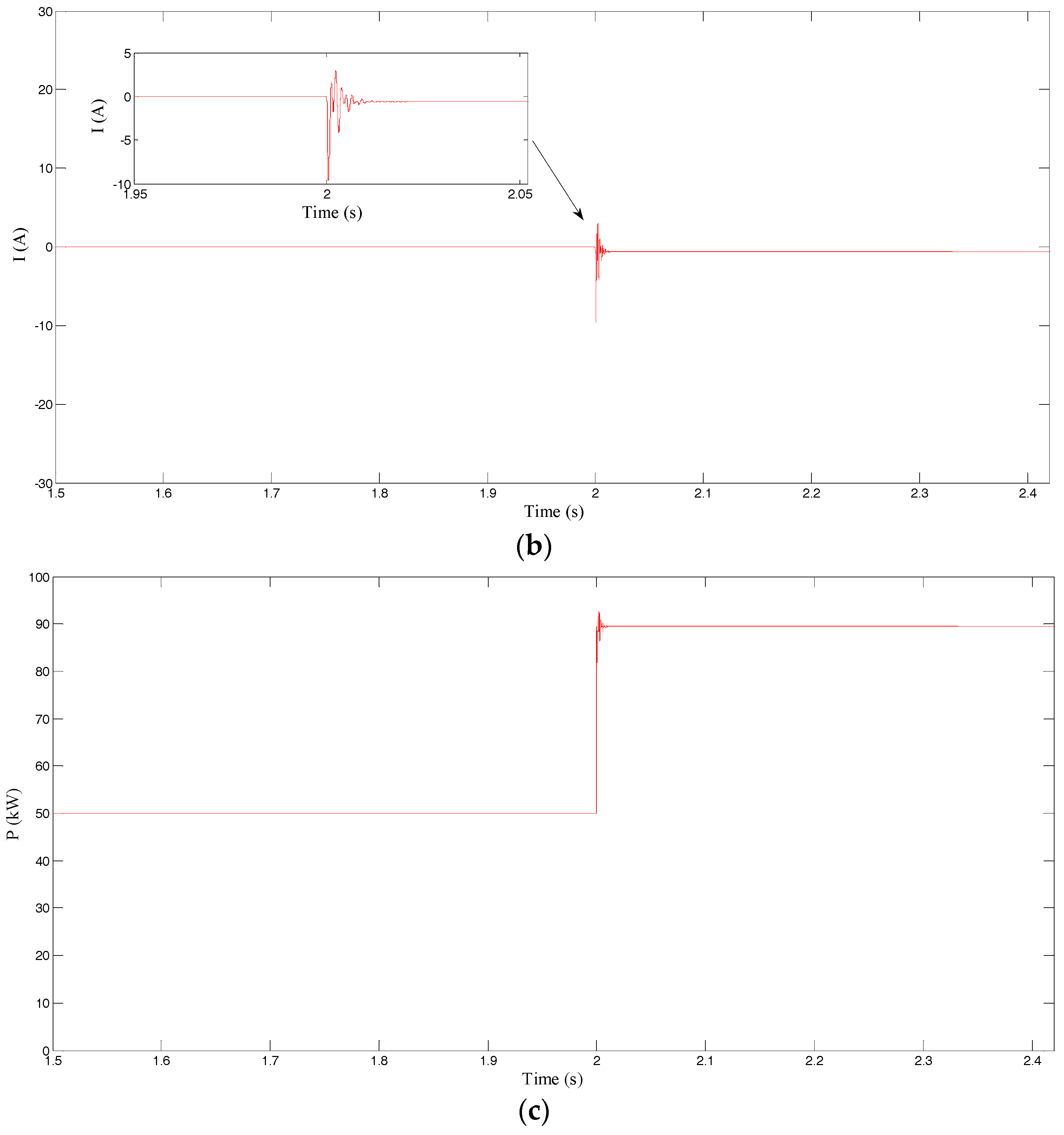
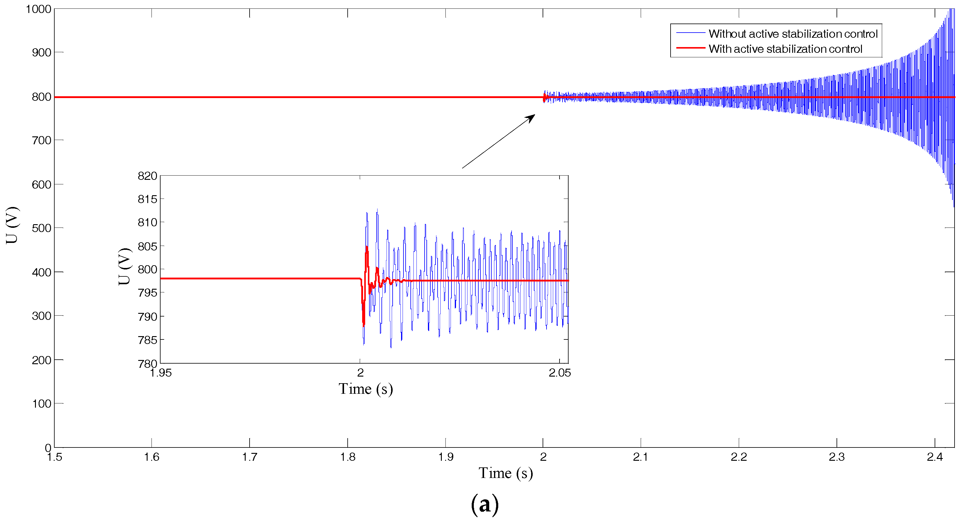
Active stabilization control was applied in a simulation model of the LV multi-terminal AC/DC hybrid system described in Section 3.3, and the local controller of the DC/DC converter (as a grid-connected interface of BESS with Pdc = 30 kW), slave VSC1, and slave VSC2, respectively, receive idc,active, is1,active, and is2,active, and then superpose the active stabilization current on the respective received power-scheduling command. Figure 8, Figure 9 and Figure 10, respectively, describe the simulation results of the DC/DC converter, slave VSC1, and slave VSC2 when the operation point (Ps1 = 50 kW, Ps2 = 50 kW) is changed to (Ps1 = 90 kW, Ps2 = 50 kW) at t = 2 s, with active stabilization control of the multi-terminal VSC and DC/DC converter.
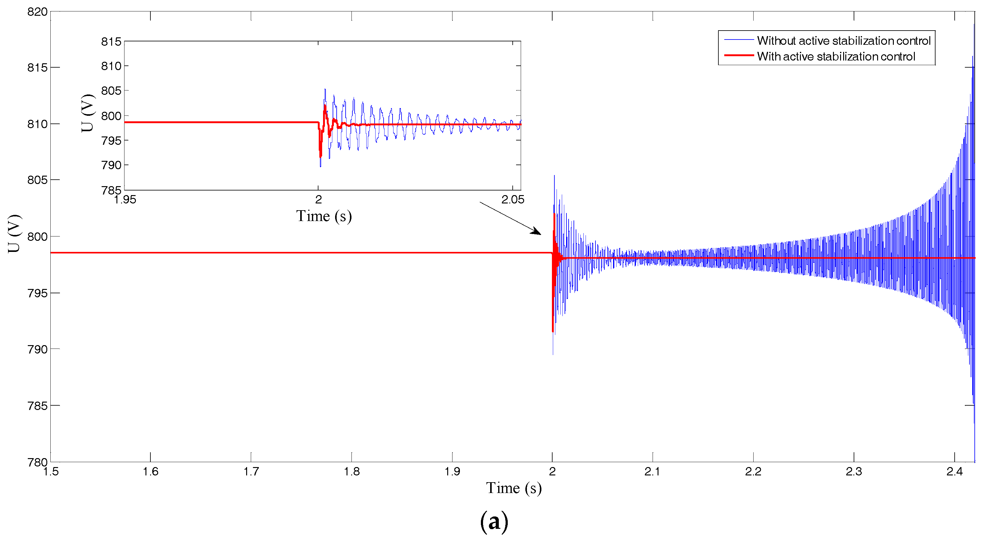
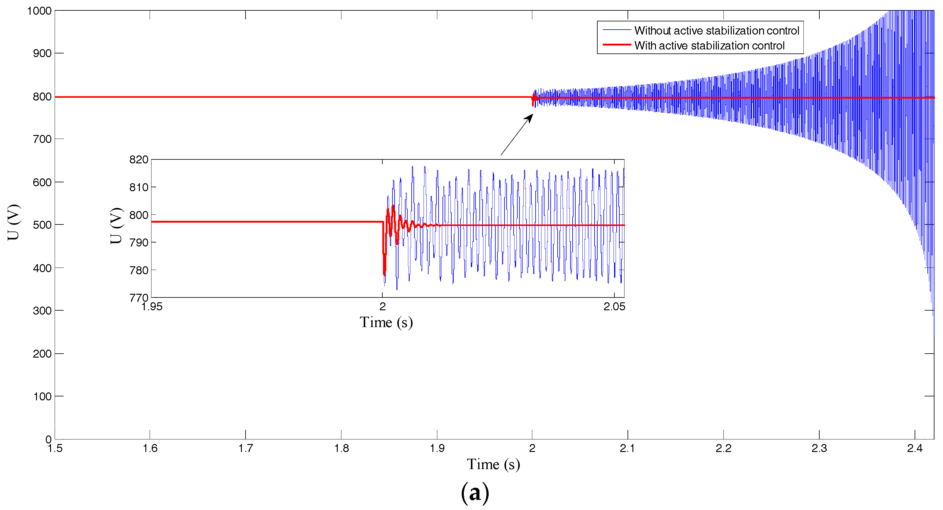
As shown in Figure 8a, Figure 9a and Figure 10a, Udc, Us1, and Us2 cannot be restored to a stable voltage until instability without active stabilization control when Ps1 is increased to 90 kW. It is worth noting that after implementation of active stabilization control, Udc, Us1, and Us2 can be stabilized quickly, within 40 ms, after a small amplitude oscillation.
As shown in Figure 8b, Figure 9b and Figure 10b, idc,active, is1,active, and is2,active are generated by the system global active stabilizer when Ps1 changes, providing for additional damping control on the existing local controller of the DC/DC converter, slave VSC1, and slave VSC2. These currents restore steady state quickly after short-term oscillation with a small amplitude, the same as Pdc, Ps1, and Ps2 shown in Figure 8c, Figure 9c and Figure 10c.
Before the implementation of active stabilization control of the multi-terminal VSC and DC/DC converter, the operation point (Ps1 = 90 kW, Ps2 = 50 kW) is in the unstable region, as indicated in Figure 4c, so the DC voltage appears unsteady. However, the stable operation boundary has been significantly expanded when active stabilization control is applied, as shown in Figure 7, and the operation point (Ps1 = 90 kW, Ps2 = 50 kW) is already in the stable region. The simulation results show that active stabilization control of the multi-terminal VSC and DC/DC converter can overstep the power limitation in order to prove the stability of a LV multi-terminal AC/DC hybrid system with a stable DC voltage, even under an unstable operation point defined before the implementation of the active stabilization control.
5.2. Active Stabilization Control of Multi-Terminal VSC
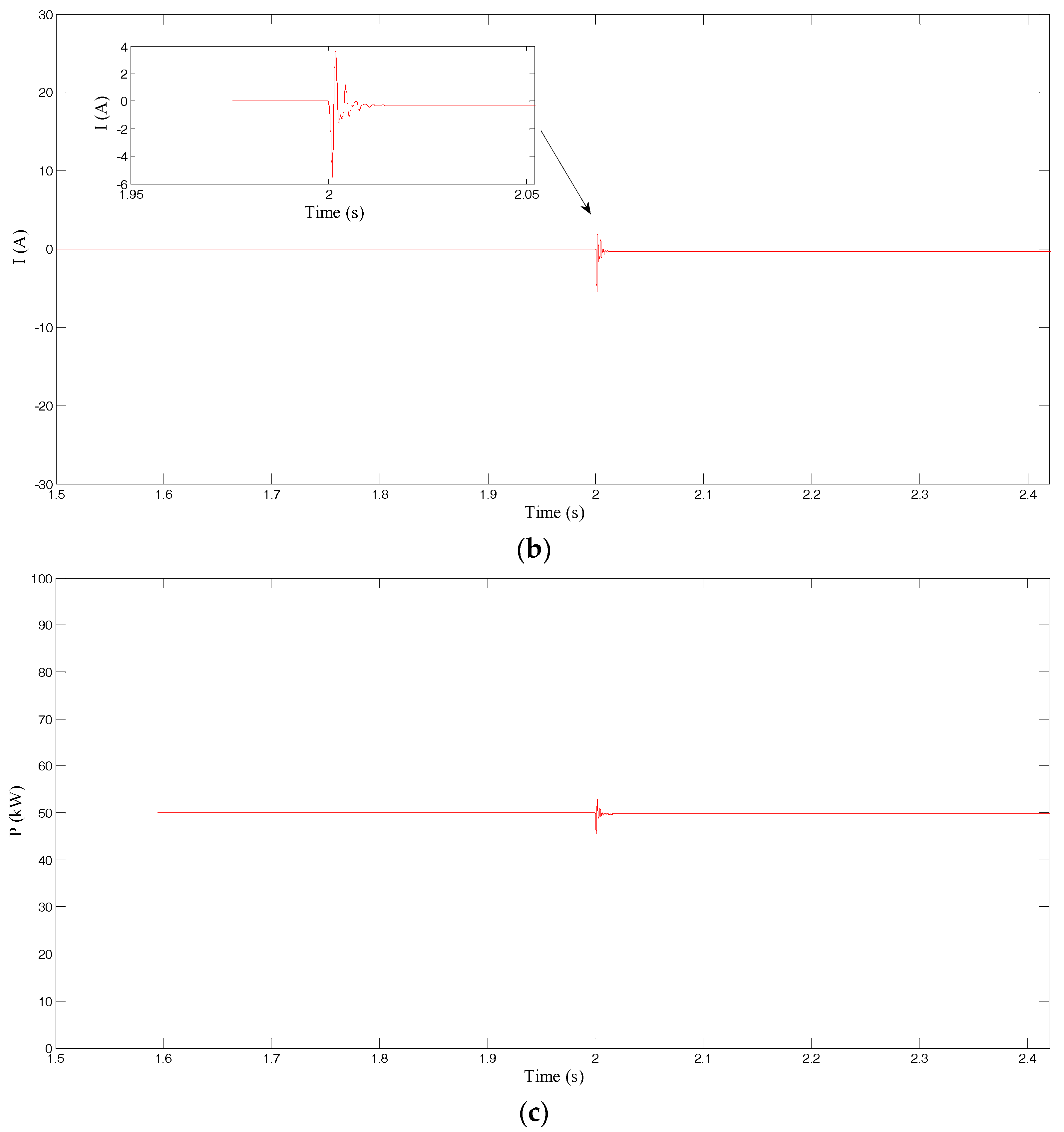
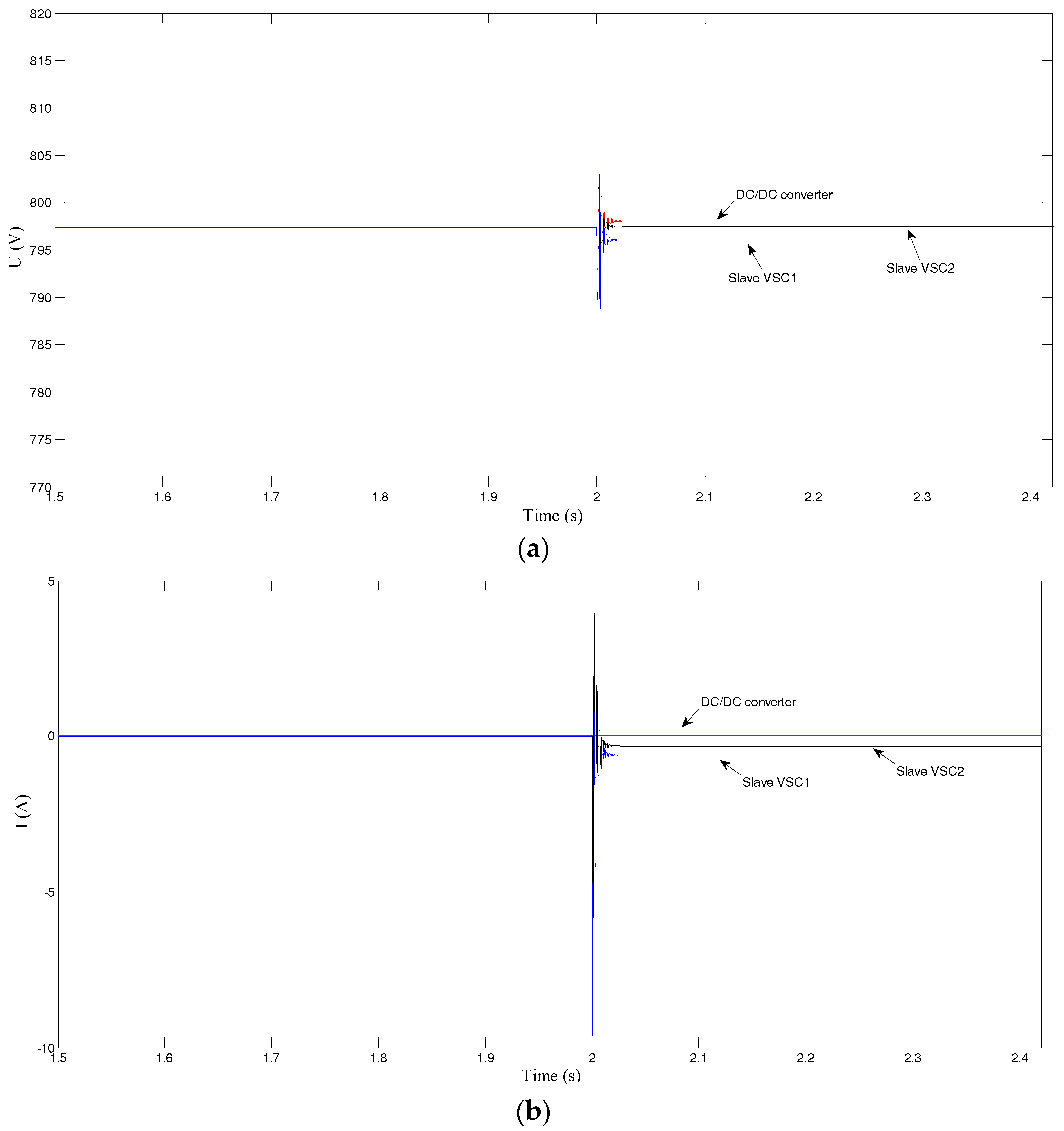
The local controllers of slave VSC1 and slave VSC2 carry out active stabilization control in the simulation model of the LV multi-terminal AC/DC hybrid system described in Section 3.3, assuming that the power of the DC/DC converter is uncontrollable with Pdc = 30 kW, so it cannot participate in active stabilization control. Figure 11 describes the simulation results of the DC/DC converter, slave VSC1, and slave VSC2, when the operation point (Ps1 = 50 kW, Ps2 = 50 kW) is changed to (Ps1 = 90 kW, Ps2 = 50 kW) at t = 2 s, with active stabilization control of the multi-terminal VSC.
As known from Section 4.2, the local controller of slave VSC1 and slave VSC2 will, respectively, receive is1,active and is2,active, generated by the system global active stabilizer, and then superpose the active stabilization current on each received power-scheduling command. Since the DC/DC converter cannot participate in active stabilization control, idc,active = 0 and its active power is a constant 30 kW.
When Ps1 changes at t = 2 s, Udc, Us1, and Us2 can all be rapidly restored to a stable voltage, as shown in Figure 11a. is1,active and is2,active reach stability quickly after a slight oscillation, and are very small compared to the steady state reference value of the corresponding slave VSC, as shown in Figure 11b. Ps1 quickly tracks the power-scheduling command and changes from 50 kW to 90 kW; and Ps2 is restored to its steady state after a short time adjustment, while Pdc remains stable during the whole process, as shown in Figure 11c.
Thus, active stabilization control of a multi-terminal VSC, just like the active stabilization control of a multi-terminal VSC and DC/DC converter, can also overstep the power limitation of VSCs with only a small control cost in order to realize system global stability and a stable voltage of the DC network in some operating conditions that would otherwise be unstable.
5.3. Comparison of the Two Methods
The active stabilization control methods studied in Section 5.1 and Section 5.2 can both effectively stabilize the system voltage, and their control effects are compared in Table 2.
It is known from the comparison data in Table 2, during the process of the voltage’s dynamic adjustment, that the oscillation amplitude of Udc, Us1, and Us2 using active stabilization control of the multi-terminal VSC and DC/DC converter is less than it is under active stabilization control of the multi-terminal VSC, and that each adjustment time using the former method is also about half that of the latter method. The results show that when the DC/DC converter participates in system-coordinated control with the multi-terminal VSC, the degree-of-freedom or flexibility of power regulation and its regulation ability can be increased for active stabilization control in order to further enhance the control effect and performance based on stable coordinated control.
5.4. Simulation for Tripping Converter
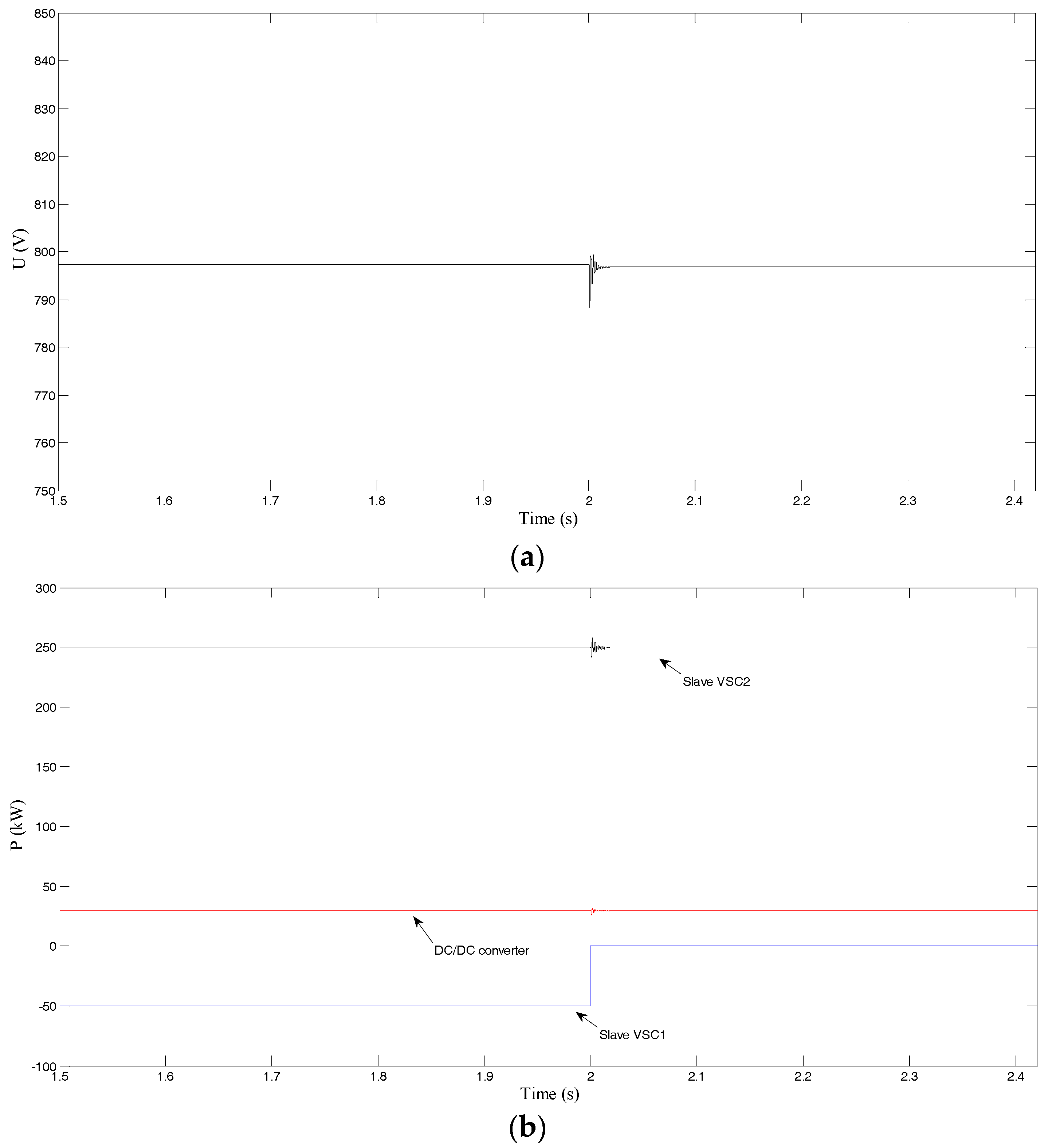
In an LV multi-terminal AC/DC hybrid system, tripping a converter will affect the system’s stable operation and even lead to DC voltage instability. In the simulation model described in Section 3.3, slave VSC1 adopts P and Q control with Ps1 = −50 kW, injecting the power of AC system 2 into the DC system. Slave VSC2 adopts P and Q control with Ps2 = 250 kW, injecting power of the DC system into AC system 3. The DC/DC converter is used as a load, with Pdc = 30 kW. Slave VSC1 is tripped at t = 2 s; the simulation waveform of Udc without active stabilization control is shown in Figure 12, and the simulation results with active stabilization control of the multi-terminal VSC and DC/DC converter are shown in Figure 13.
When slave VSC1 is tripped, Udc appears as a divergent oscillation until instability without active stabilization control, as shown in Figure 12. After implementation of active stabilization control, when slave VSC1 is tripped (Ps1 decreases to 0 kW), Udc can quickly recover stability after a short period of slight voltage oscillation, while Ps2 and Pdc quickly reach the steady-state value after small fluctuations, ensuring the normal work of the DC system.
6. Conclusions
This paper discusses the typical structure and coordinated control mode of a low-voltage multi-terminal AC/DC hybrid system. It takes a three-terminal system, including a DC network as the research object, in order to carry out a stability analysis of a low-voltage multi-terminal AC/DC hybrid system, then studies the relationship between the stable operation boundary of the VSCs and their transmitted power and explores the instability of the DC voltage.
An active stabilization-control method based on the Lyapunov theory is proposed, and the hierarchical control scheme of the low-voltage multi-terminal AC/DC hybrid system, with a system global active stabilizer and local controller of each control object, is established. The active stabilization-control method proposed in this paper can use the system’s global information, more than just local information for each local controller, and the quadratic optimal control theory is used to adjust the state-feedback matrix dynamically. In fact, the introduction of the state-feedback control can provide additional damping for the system. When disturbance occurs, it will be damped due to the action of the controller, and the state variable will follow the original, given signal by the role of feedback. The research shows that the chosen feedback law can provide effective additional damping for system control, and ensure the system’s global stability. It can overstep the original power limitation of VSCs in order to maintain stable DC voltage, even at some operation point that would otherwise be unstable without active stabilization control.
At the same time, the effect of the additional control signals of each control object on damping system oscillation is analyzed, and the results show that active stabilization control of the VSC with additional damping is the main factor in global stabilization. Based on that, equipment in the DC network participates in the coordinated control and can further enhance the control effect. Finally, a set of electromagnetic transient simulations verify the effectiveness of the proposed active stabilization control method.
Acknowledgments
This research was supported by the National Key Research and Development Program of China (2017YFB0903300), and the Key Front Science Project of the Chinese Academy of Sciences (QYZDB-SSW-JSC024).
Author Contributions
The authors contributed equally in the preparation of this manuscript.
Conflicts of Interest
The authors declare no conflict of interest.
References
- Shamsi, P.; Fahimi, B. Stability assessment of a DC distribution network in a hybrid micro-grid application. IEEE Trans. Smart Grid 2014, 5, 2527–2534. [Google Scholar] [CrossRef]
- Lee, S.H.; Kang, Y.C.; Park, J.W. Optimal operation of multiple DGs in DC distribution system to improve system efficiency. IEEE Trans. Ind. Appl. 2016, 52, 3673–3681. [Google Scholar] [CrossRef]
- Deng, W.; Pei, W.; Shen, Z.Q.; Zhao, Z.X.; Qu, H. Adaptive Micro-Grid Operation Based on IEC 61850. Energies 2015, 8, 4455–4475. [Google Scholar] [CrossRef]
- Chen, S.M.; Liang, T.J.; Hu, K.R. Design, analysis, and implementation of solar power optimizer for DC distribution system. IEEE Trans. Power Electron. 2013, 28, 1764–1772. [Google Scholar] [CrossRef]
- Davari, M.; Mohamed, Y.A.R.I. Robust multi-objective control of VSC-based DC-voltage power port in hybrid AC/DC multi-terminal micro-grids. IEEE Trans. Smart Grid 2013, 4, 1597–1612. [Google Scholar] [CrossRef]
- Chaudhary, S.K.; Guerrero, J.M.; Teodorescu, R. Enhancing the capacity of the AC distribution system using DC interlinks—A step toward future DC grid. IEEE Trans. Smart Grid 2015, 6, 1722–1729. [Google Scholar] [CrossRef]
- Hosseinzadeh, M.; Salmasi, F.R. Robust optimal power management system for a hybrid AC/DC micro-grid. IEEE Trans. Sustain. Energy 2015, 6, 675–687. [Google Scholar] [CrossRef]
- Peña-Alzola, R.; Bianchi, M.A.; Ordonez, M. Control design of a PFC with harmonic mitigation function for small hybrid AC/DC buildings. IEEE Trans. Power Electron. 2016, 31, 6607–6620. [Google Scholar] [CrossRef]
- Eghtedarpour, N.; Farjah, E. Power control and management in a hybrid AC/DC microgrid. IEEE Trans. Smart Grid 2014, 5, 1494–1505. [Google Scholar] [CrossRef]
- Boroyevich, D.; Cvetkovic, I.; Dong, D. Future electronic power distribution systems: A contemplative view. In Proceedings of the 2010 12th International Conference on Optimization of Electrical and Electronic Equipment, Basov, Russia, 20–22 May 2010; Volume 1, pp. 1369–1380. [Google Scholar]
- Liang, Z.; Guo, R.; Li, J. A high-efficiency PV module-integrated DC/DC converter for PV energy harvest in FREEDM systems. IEEE Trans. Power Electron. 2011, 26, 897–909. [Google Scholar] [CrossRef]
- Kakigano, H.; Miura, Y.; Ise, T. Low-voltage bipolar-type DC microgrid for super high quality distribution. IEEE Trans. Power Electron. 2010, 25, 3066–3075. [Google Scholar] [CrossRef]
- Bifaretti, S.; Zanchetta, P.; Watson, A. Advanced power electronic conversion and control system for universal flexible power management. IEEE Trans. Smart Grid 2011, 2, 231–243. [Google Scholar] [CrossRef]
- Li, K.; Wei, P.; Hua, Y.; Xue, Z.; Zekun, L.; Yao, L.; Jin, J. Review of pattern, control and stability for hybrid AC/DC distribution power systems. Adv. Technol. Electr. Eng. Energy 2017, 36, 1–10. (In Chinese) [Google Scholar]
- Liu, X.; Wang, P.; Loh, P.C. A hybrid AC/DC microgrid and its coordination control. IEEE Trans. Smart Grid 2011, 2, 278–286. [Google Scholar]
- Ritwik, M. A hybrid microgrid with DC connection at back to back converters. IEEE Trans. Smart Grid 2014, 5, 251–259. [Google Scholar]
- Zhang, X.; Pei, W.; Deng, W.; Qu, H.; Shen, Z.Q.; Zhao, Z.X. Energy management and coordinated control method for multi-source/multi-load DC microgrid. Proc. Chin. Soc. Electr. Eng. 2014, 34, 5553–5562. (In Chinese) [Google Scholar]
- Xiao, H.; Luo, A.; Shuai, Z.; Jin, G.; Huang, Y. An improved control method for multiple bidirectional power converters in hybrid ac/dc microgrid. IEEE Trans. Smart Grid 2016, 7, 340–347. [Google Scholar] [CrossRef]
- Loh, P.C.; Ding, Li.; Chai, Y.; Blaabjerg, F. Autonomous operation of hybrid microgrid with ac and dc subgrids. IEEE Trans. Power Electron. 2013, 28, 2214–2223. [Google Scholar] [CrossRef]
- Peyghami, S.; Mokhtari, H.; Blaabjer, F. Autonomous operation of a hybrid ac/dc microgrid with multiple interlinking converters. IEEE Trans. Smart Grid 2017. [Google Scholar] [CrossRef]
- Sulligoi, G.; Bosich, D.; Giadrossi, G.; Zhu, L.; Cupelli, M.; Monti, A. Multiconverter medium voltage DC power systems on ships: Constant-power loads instability solution using linearization via state feedback control. IEEE Trans. Smart Grid 2014, 5, 2543–2552. [Google Scholar] [CrossRef]
- Marx, D.; Magne, P.; Nahid-Mobarakeh, B.; Pierfederici, S.; Davat, B. Large signal stability analysis tools in DC power systems with constant power loads and variable power loads—A review. IEEE Trans. Power Electron. 2012, 27, 1773–1787. [Google Scholar] [CrossRef]
- Magne, P.; Nahid-Mobarakeh, B.; Pierfederici, S. General active global stabilization of multiloads DC-power networks. IEEE Trans. Power Electron. 2012, 27, 1788–1798. [Google Scholar] [CrossRef]
- Khalil, H. Nonlinear Systems, 3rd ed.; Prentice-Hall, Inc.: Upper Saddle River, NJ, USA, 2002. [Google Scholar]
Figure 1.
Structure of a low-voltage (LV) multi-terminal AC/DC hybrid system.

Figure 2.
Typical control strategies of utility-interfacing voltage-source converter (VSC).
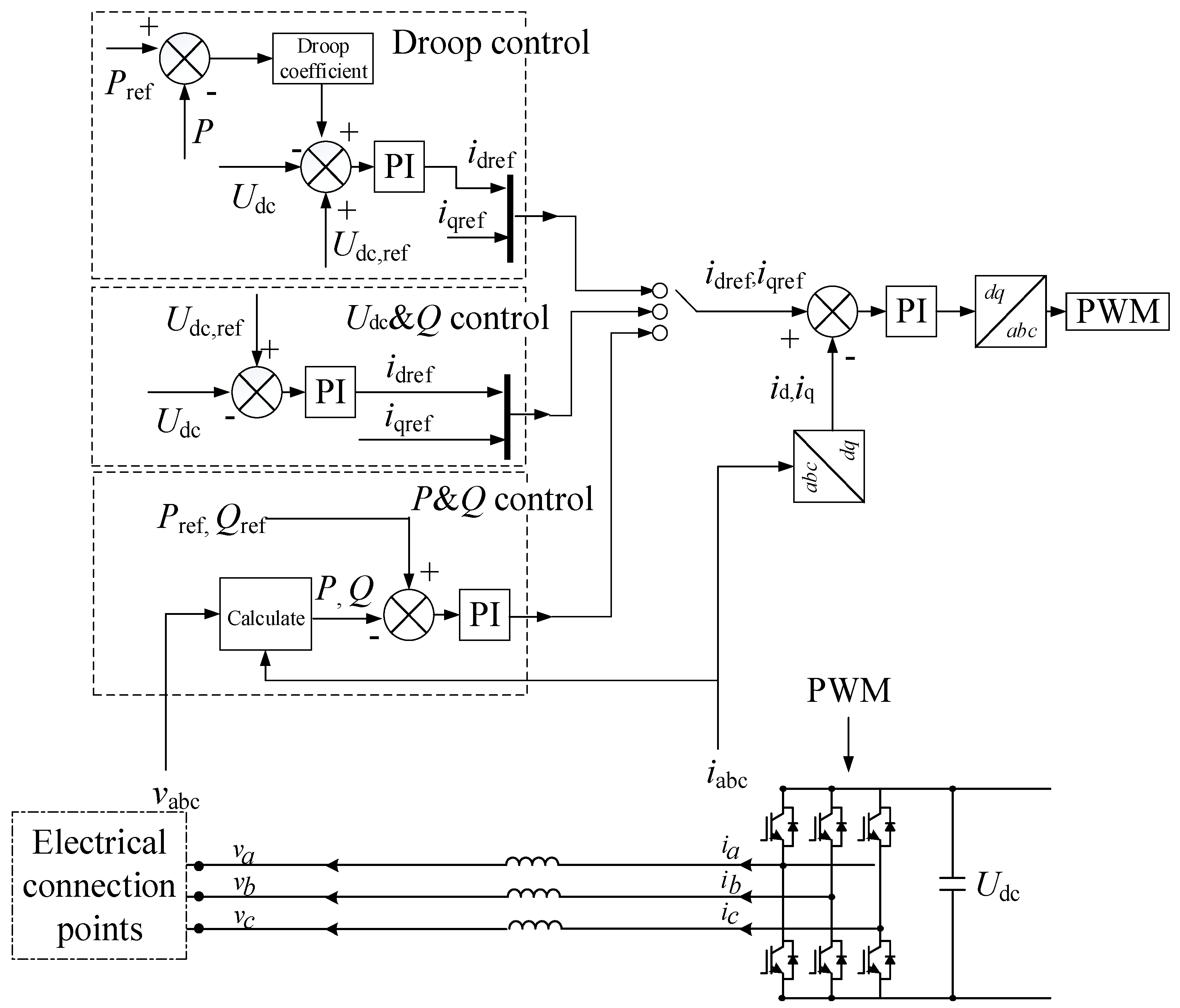
Figure 3.
Equivalent structure of LV multi-terminal AC/DC hybrid system.

Figure 4.
Stable operation boundary of slave VSC1 and slave VSC2 under three conditions: (a) Pdc = −30 kW; (b) Pdc = 0 kW; and (c) Pdc = 30 kW.
Figure 4.
Stable operation boundary of slave VSC1 and slave VSC2 under three conditions: (a) Pdc = −30 kW; (b) Pdc = 0 kW; and (c) Pdc = 30 kW.


Figure 5.
Simulation waveform of Udc: (a) changing Ps1 from 50 kW to 80 kW at t = 2 s; and (b) changing Ps1 from 50 kW to 90 kW at t = 2 s.
Figure 5.
Simulation waveform of Udc: (a) changing Ps1 from 50 kW to 80 kW at t = 2 s; and (b) changing Ps1 from 50 kW to 90 kW at t = 2 s.
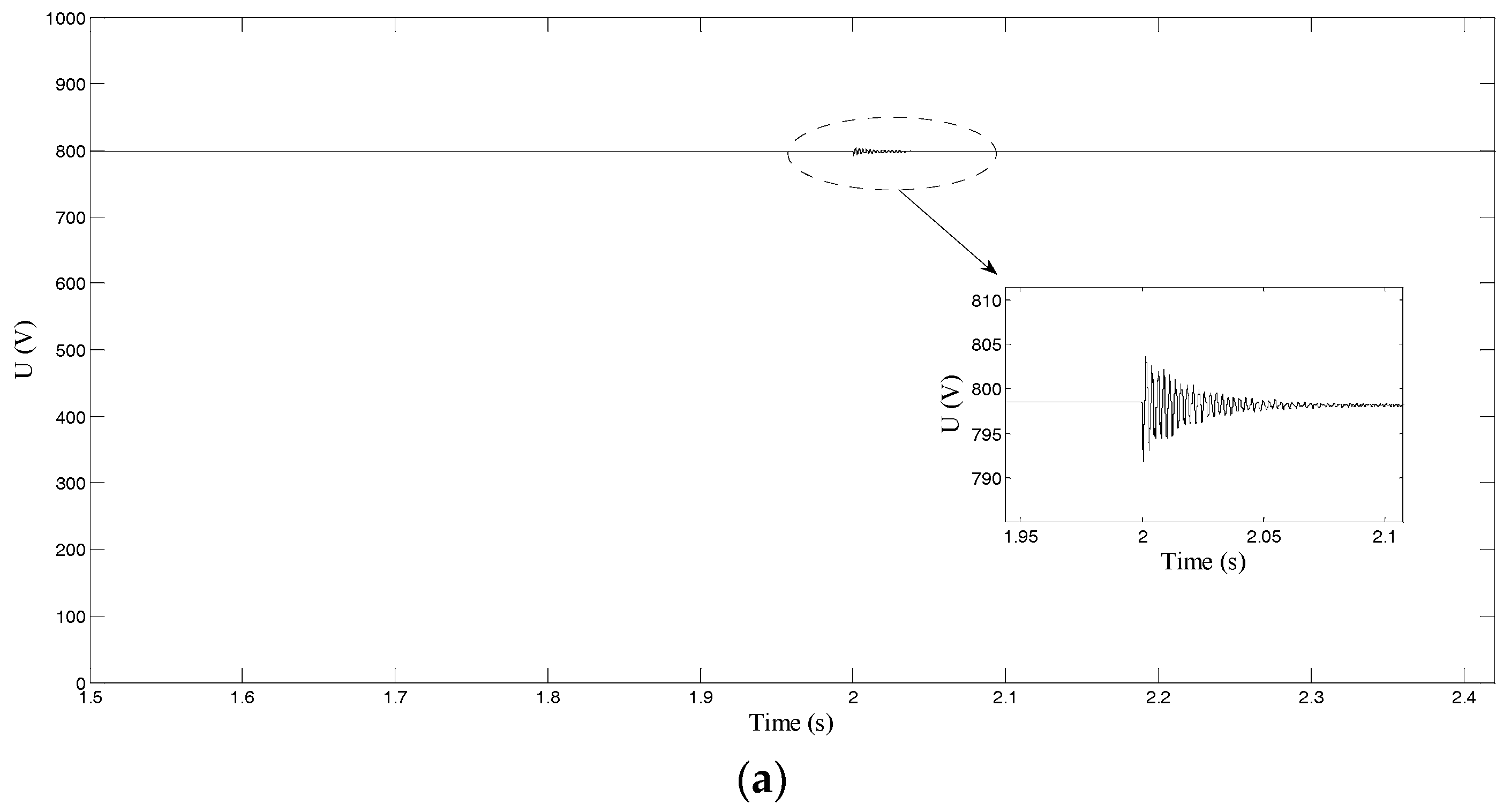

Figure 6.
Active stabilization control scheme of the LV multi-terminal AC/DC hybrid system.
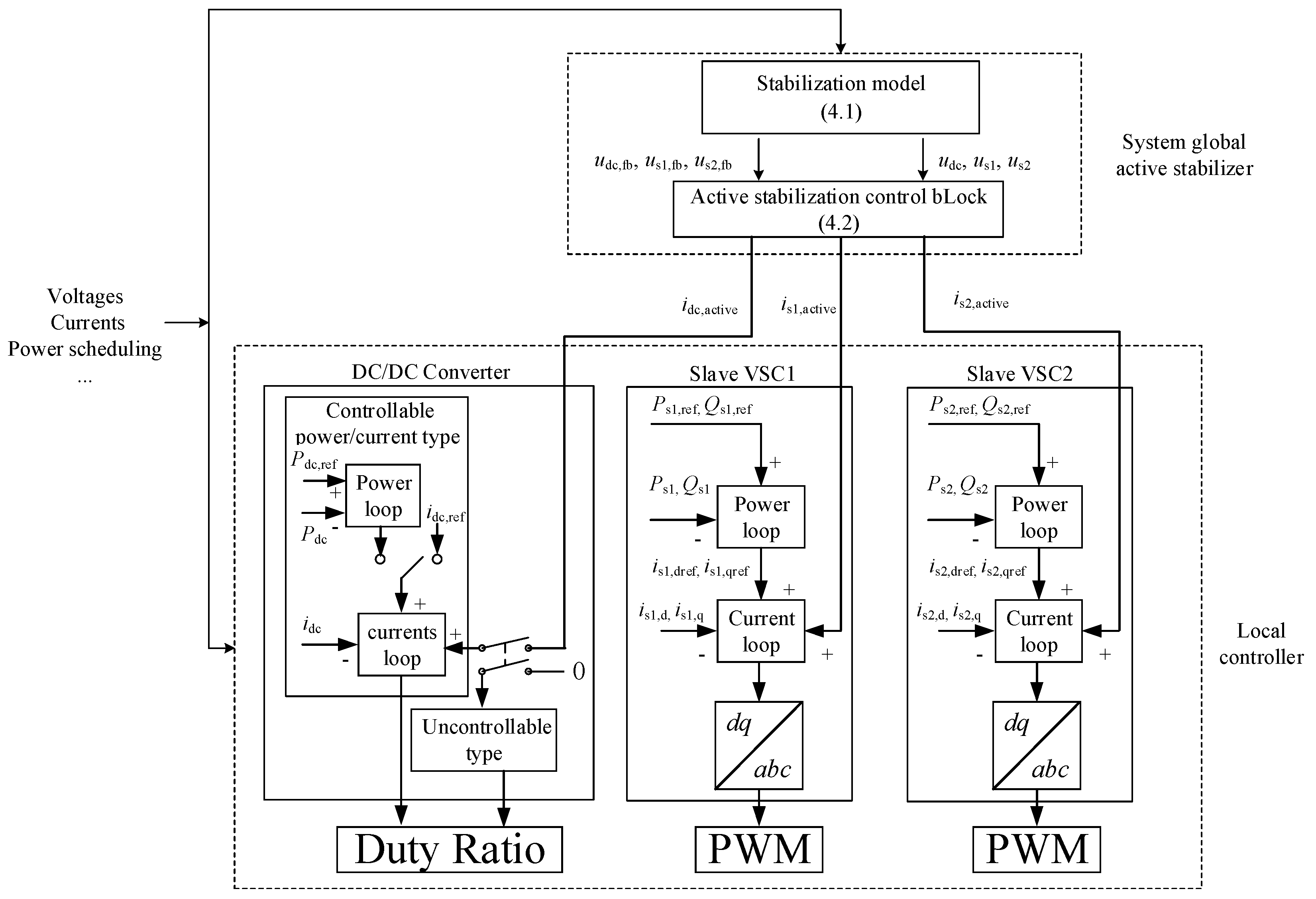
Figure 7.
Stable operation boundary of slave VSC1 and slave VSC2 when Pdc = 30 kW after active stabilization control.
Figure 7.
Stable operation boundary of slave VSC1 and slave VSC2 when Pdc = 30 kW after active stabilization control.

Figure 8.
Simulation waveform by changing Ps1 = 50 kW to Ps1 = 90 kW at t = 2 s: (a) Udc; (b) idc,active; and (c) Pdc.
Figure 8.
Simulation waveform by changing Ps1 = 50 kW to Ps1 = 90 kW at t = 2 s: (a) Udc; (b) idc,active; and (c) Pdc.

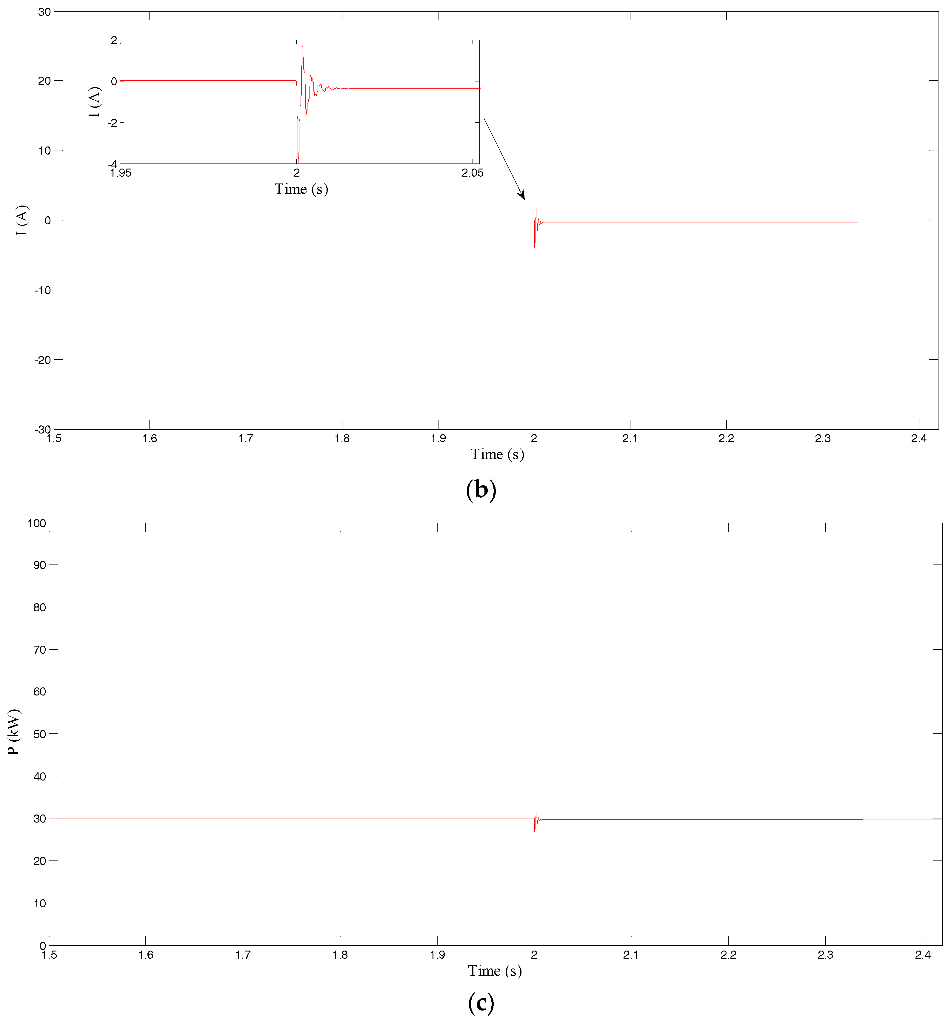
Figure 9.
Simulation waveform by changing Ps1 = 50 kW to Ps1 = 90 kW at t = 2 s: (a) Us1; (b) is1,active; and (c) Ps1.
Figure 9.
Simulation waveform by changing Ps1 = 50 kW to Ps1 = 90 kW at t = 2 s: (a) Us1; (b) is1,active; and (c) Ps1.


Figure 10.
Simulation waveform by changing Ps1 = 50 kW to Ps1 = 90 kW at t = 2 s: (a) Us2; (b) is2,active; and (c) Ps2.
Figure 10.
Simulation waveform by changing Ps1 = 50 kW to Ps1 = 90 kW at t = 2 s: (a) Us2; (b) is2,active; and (c) Ps2.


Figure 11.
Simulation waveform by changing Ps1 = 50 kW to Ps1 = 90 kW at t = 2 s: (a) DC voltages; (b) active stabilization currents; and (c) active power.
Figure 11.
Simulation waveform by changing Ps1 = 50 kW to Ps1 = 90 kW at t = 2 s: (a) DC voltages; (b) active stabilization currents; and (c) active power.

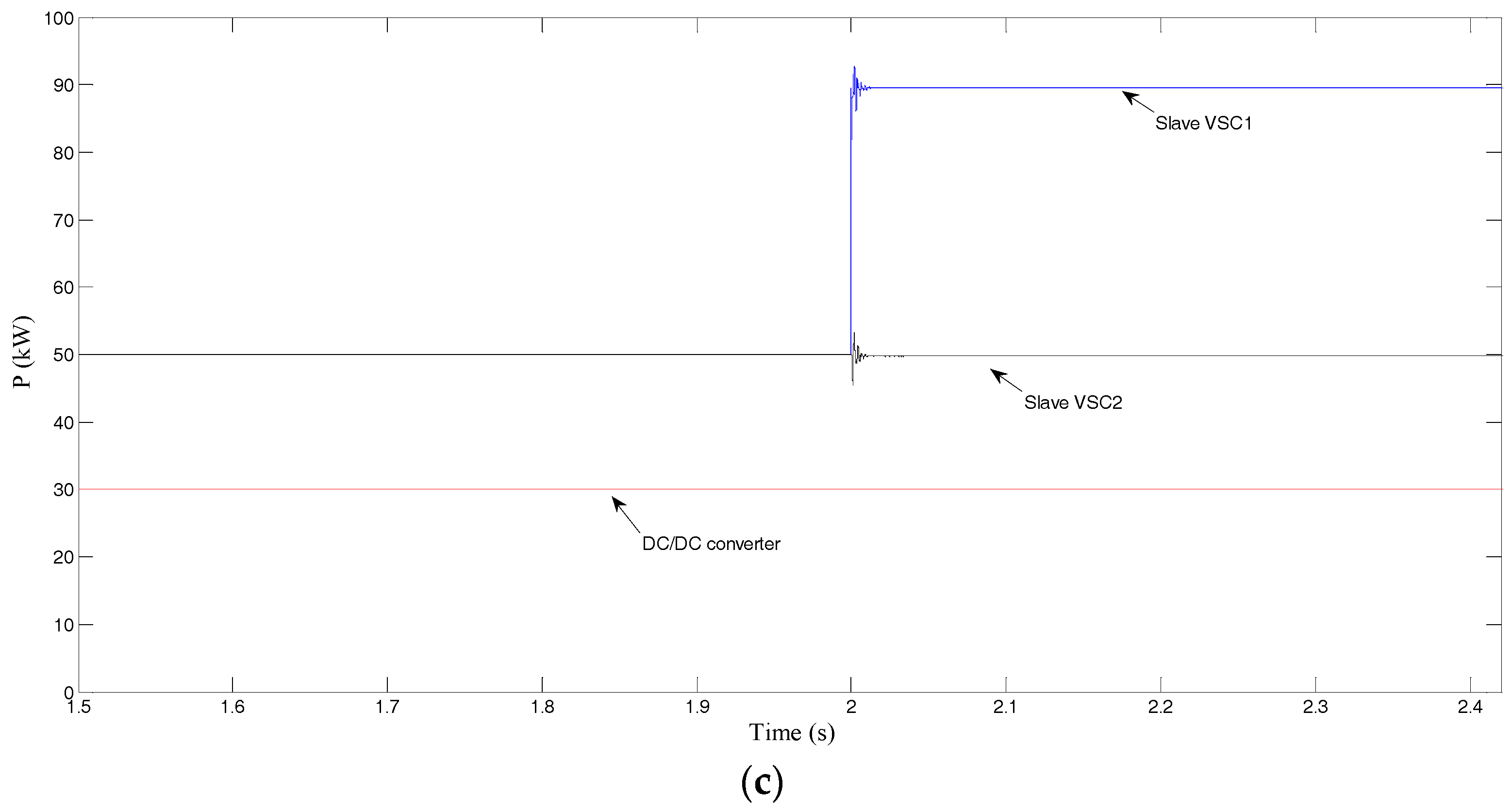
Figure 12.
Simulation waveform of Udc when tripping slave VSC1 at t = 2 s without active stabilization control.
Figure 12.
Simulation waveform of Udc when tripping slave VSC1 at t = 2 s without active stabilization control.

Figure 13.
Simulation waveform when tripping slave VSC1 at t = 2 s with active stabilization control of the multi-terminal VSC and DC/DC converter: (a) Udc; and (b) active power.
Figure 13.
Simulation waveform when tripping slave VSC1 at t = 2 s with active stabilization control of the multi-terminal VSC and DC/DC converter: (a) Udc; and (b) active power.

Table 1.
Parameters of equivalent structure of LV multi-terminal AC/DC hybrid system.
| Symbol | Value | Symbol | Value |
|---|---|---|---|
| rm | 0.0091 Ω | Ls2 | 0.04469 mH |
| Lm | 0.04469 mH | Cs2 | 1050 μF |
| Cdc | 1000 μF | Um | 800 V |
| rs1 | 0.0182 Ω | Pm,rated | 500 kW |
| Ls1 | 0.0894 mH | Ps1,rated | 100 kW |
| Cs1 | 500 μF | Ps2,rated | 300 kW |
| rs2 | 0.009 Ω | Pdc,rated | 80 kW |
Table 2.
Comparison of two kinds of active stabilization control.
| Symbol | Multi-Terminal VSC and DC/DC Converter | Multi-Terminal VSC | ||
|---|---|---|---|---|
| Oscillation Peak (%) | Adjustment Time | Oscillation Peak (%) | Adjustment Time | |
| Udc | 0.79 | 0.025 s | 0.85 | 0.04 s |
| Us1 | 2.25 | 0.035 s | 2.26 | 0.06 s |
| Us2 | 1.19 | 0.023 s | 1.25 | 0.045 s |
© 2018 by the authors. Licensee MDPI, Basel, Switzerland. This article is an open access article distributed under the terms and conditions of the Creative Commons Attribution (CC BY) license (http://creativecommons.org/licenses/by/4.0/).
Share and Cite
MDPI and ACS Style
Deng, W.; Pei, W.; Li, L. Active Stabilization Control of Multi-Terminal AC/DC Hybrid System Based on Flexible Low-Voltage DC Power Distribution. Energies 2018, 11, 502. https://doi.org/10.3390/en11030502
AMA Style
Deng W, Pei W, Li L. Active Stabilization Control of Multi-Terminal AC/DC Hybrid System Based on Flexible Low-Voltage DC Power Distribution. Energies. 2018; 11(3):502. https://doi.org/10.3390/en11030502
Chicago/Turabian StyleDeng, Wei, Wei Pei, and Luyang Li. 2018. "Active Stabilization Control of Multi-Terminal AC/DC Hybrid System Based on Flexible Low-Voltage DC Power Distribution" Energies 11, no. 3: 502. https://doi.org/10.3390/en11030502
Note that from the first issue of 2016, this journal uses article numbers instead of page numbers. See further details here.