Adaptive Stabilization and Dynamic Performance Preservation of Cascaded DC-DC Systems by Incorporating Low Pass Filters


Department of Electrical and Computer Engineering, The George Washington University, Washington, DC 20052, USA
*
Author to whom correspondence should be addressed.
†
These authors contributed equally to this work.
Energies 2018, 11(2), 440; https://doi.org/10.3390/en11020440
Submission received: 18 January 2018
/
Revised: 11 February 2018
/
Accepted: 12 February 2018
/
Published: 15 February 2018
Abstract
:This paper proposes a method to stabilize and enhance the dynamic performance of a cascaded DC-DC system by adaptively reshaping the source output impedance. The method aims to reduce the ratio of the source output impedance to the load input impedance, referred to as the minor loop gain, to eliminate the interaction between the load and the source systems. This interaction can deteriorate the dynamic performance or might lead to instability. Thus, the bus current is used to improve the dynamic performance by reducing the magnitude of the source’s output impedance adaptively according to the loading condition such that the dynamic performance is consistently improved. Utilizing the bus current facilitates the compatibility between the proposed controller and most widely used DC-DC converters controlled in voltage mode, including non-minimum phase converters. In addition to the flexibility the bus current provides to embed the proposed solution with conventional control schemes. Experimental results have validated the effectiveness of the proposed controller along with time-based simulation and theoretical analysis, for minimum and non-minimum phase converters.
1. Introduction
Cascaded DC-DC systems have been widely used in aerospace, maritime, and automobile industries due to their attractive features such as modularity, scalability, high power density, and high reliability [1]. They provide a flexible environment to efficiently integrate renewable energy resources with the existing power systems [2,3]. Typically, a cascaded system consists of a line regulating converter (LRC) [4], which acts as the source, connected in series with a load subsystem, as shown in Figure 1. The load system might consist of DC-DC converters, inverters, or a combination connected in parallel [5]. Since most load converter modules are tightly regulated and supply a load with one-to-one characteristic of voltage-to-current or speed-to-torque relationships [6,7], these modules act as constant power loads (CPL). CPLs exhibit a negative incremental impedance seen by the LRC [8]. This characteristic is notorious for degrading the dynamic performance of cascaded systems and might lead to instability [9].
Assessing the stability and the dynamic performance of cascaded DC-DC systems was initiated by R.D. Middlebrook in 1976, who studied the impact of the input filters on the stability and on the performance of regulated DC-DC converters [8]. His study resulted in the Middlebrook criterion, which ensures the stability and performance of cascaded systems. It is based on relating the ratio of the source output impedance to the load input impedance, which is called the minor loop gain () in Figure 1), to system stability properties. The criterion is deemed to be very conservative [3], and requires infinite phase margin. Consequently, high capacitance is needed at the DC bus to achieve the required phase margin. Those requirements are impractical because they reduce the power density of cascaded systems, which is not desirable for most applications. To relax the conservativeness imposed by the Middlebrook criterion, other criteria have been proposed in the literature such as the Gain Margin Phase Margin (GMPM) [10], the Opposing Argument [11], and Energy Source Analysis Consortium (ESAC) [12], which in various ways confine the polar plot of in a specific region of the complex plane to guarantee acceptable dynamic performance [2,13]. All these criteria assume that the load and the source converters are standalone stable. The Three-Steps criterion was introduced in [14] to assess the stability of cascaded systems even if the source converter was standalone unstable. In addition, the Passivity-Based criterion was introduced in [15] to further relax the artificial conservativeness of designing cascaded systems. It examines the stability of a cascaded system by injecting current into the DC bus to determine the passivity of the bus impedance. Bus impedance passivity would ensure stability. All of the above mentioned criteria provide sufficient conditions to ensure stability or dynamic performance, so their violation does not necessarily mean instability.
It is desirable to implement the system of Figure 1 in a modular and scalable manner, such that it can host various load and source subsystems from different vendors [2]. However, these miscellaneous components have different dynamic properties and ensuring stability with satisfactory performance of such an assorted system is a challenging task. Hence, passive damping methods have been proposed to preserve the stability and to improve the dynamic performance of such a system. Using passive components to damp out system oscillations incurs inevitable power loss that reduces the overall efficiency. In addition, passive damping reduces the power density of the system by including bulky passive components.
Active damping methods were introduced to overcome the passive damping disadvantages [1,9,16]. In this approach, stability is ensured by modifying the control loop of the LRC or the load system. However, in the existing active damping methods, little attention has been given to preservation or improvement of system dynamic behavior, and it is typically compromised in favor of ensuring system stability. The existing solutions for enhancing the dynamic performance are either applicable to a single load converter, or limited to a particular configuration of source (LRC) DC-DC converter. In [17], the stability of the system has been exclusively ensured for buck converters, as the LRC, via adding extra feedback loops to modify the inductor’s series resistance. Although the system stability is guaranteed, the dynamic performance of the system is not improved because the system dynamics are changed while the controller has not been modified to accommodate that. In [18], the Middlebrook criterion was partially fulfilled; the stability condition has been met by inserting a virtual resistance in series with the load via feeding back the bus current into the controller. The performance requirement of the Middlebrook criterion was neglected. Moreover, a second controller is required to compensate for the voltage drop across the DC bus, which may introduce other stability and performance issues. In [19], the magnitude or the phase of the load’s input impedance is modified to prevent the interaction between the load and the source subsystems where the impedance overlap occurs using a band pass filter based on a method in [20]. It is achieved by inserting a virtual resistance either in series or in parallel with the load subsystem. The relative stability margins will be affected in that region, while the solution requires modifications for every converter that would be connected as a load.
In [21,22], an adaptive virtual capacitor connected to the DC bus is proposed to stabilize the system; the solution results in power density reduction because the virtual capacitor is implemented using an additional auxiliary converter, making it less desirable for density-sensitive applications. In reference [22], a method to improve the dynamic performance of a cascaded system that consists of a single DC-DC converter as the load was introduced. The proposed solution cannot handle multiple load converters operating in parallel. The authors of reference [23] proposed a method to design both source and load controllers simultaneously, such that their interaction is minimized. Similar to [22], the proposed method is solely valid for a single load DC-DC converter. The vast majority of the above mentioned active damping methods were introduced, and tested to stabilize minimum phase converters, e.g., buck converters, while the non-minimum phase converters have not received much attention in this sense.
To devise a method for ensuring stability and performance of cascaded DC-DC systems with multiple loads and to address the discussed issues, we propose a method that reshapes the output impedance of the LRC to stabilize the system and improve its dynamic performance. The proposed method is applicable to minimum and non-minimum phase converters, and it neither incurs additional power losses nor changes the LRC controller parameters. Additionally, it is applicable to linearized feedback control schemes, without changing the controller parameters. The method is based on adaptively reducing the magnitude of the source output impedance by feeding back the average value of the bus current. Consequently, the output impedance is reduced depending on the loading condition. Reducing the output impedance helps eliminate the interaction between load and source systems, and effectively decouples these two.
This paper first discusses the stability and performance issues of cascaded systems in Section 2. Then the proposed controller is explained in Section 3. The compatibility of the proposed controller with minimum and non-minimum phase converters is discussed in Section 4 and Section 5, respectively. Finally, the conclusions are drawn in Section 6.
2. Stability and Performance of Cascaded DC-DC Systems
The stability and performance of cascaded DC-DC systems are deteriorated by the incremental negative impedance exhibited by the load subsystem. The negative impedance appears to be due to the active nature of the load subsystem, which tightly regulates its output voltage while delivering a constant amount of power despite the variation in the input voltage. The mathematical derivation of the negative input impedance [24,25], is
where r is the load low frequency impedance, is the DC bus voltage, and is the DC bus current. Equation (1) can be related to the bus voltage and output power of each load converter (), assuming lossless converters [26], as
where n is the number of loads. Equations (1) and (2) are valid for the frequencies that are less than the cut-off frequency of the load converter () [8], where the impedance is . Beyond , the load input impedance resembles an inductor impedance. Typical plots of the source output impedance and the load input impedance are shown in Figure 2, [13,24,27]. The proposed stabilization method depends on the maximum frequency () of the interaction region, as illustrated in Figure 2.
The roles of and in assessing the stability of cascaded systems can be visualized using the characteristic equation of distributed DC systems [10,27] as
where is the ith load output voltage, is the source converter input voltage, is the source converter control to output transfer function, and is the ith load converter control to output transfer function. For multiple loads, the input impedance of the load system is the parallel combination of each load module input impedance, i.e., .
To determine stability properties of the cascaded system, Nyquist criterion is used [13,16]. Stability is preserved if the polar plot of does not encircle . An impedance overlap in the low-frequency region () implies and , consequently the polar plot of will encircle .
Source and load subsystems interaction alters the dynamic performance of the overall system. As a result of this interaction, the source control loop gain () is altered [28,29] as
where and are the original and load affected control loop gain of the LRC, respectively. The LRC dynamic performance stays intact from the loading effect iff , consequently in Equation (4). Moreover, if encircles , so does [16,29]. On the other hand, the dynamic performance of the load is degraded by the source according to
where is the open-loop input impedance impedance of the load converter, is the load converter control loop gain, and is source affected control loop gain of the load. Similarly, the load dynamic performance will be preserved iff , which implies in Equation (5). Since reducing helps decouple the dynamics of source and load systems, we propose to reduce the magnitude of the source output impedance based on
where is a positive constant. Having () as the divisor is justified in the next section. Using Equation (6) the minor loop gain can be re-expressed as
Increasing reduces the magnitude of , and consequently reduces , which implies and . Thus the source and the load systems are decoupled, and the Middlebrook criterion of ensuring stability and preserving the dynamic performance is satisfied without artificial conservativeness.
3. The Controller Design
The proposed controller aims to adaptively stabilize and preserve the dynamic performance of cascaded DC-DC converters without changing the LRC controller parameters. To do so, must stay intact from the loading effect as discussed earlier, and must be reshaped adaptively according to the load conditions. In addition, the closed-loop transfer function of reference voltage to output voltage () should stay as ().
In references [30,31], a controller that preserves () relationship, and reshapes the output impedance of single phase inverters or multi-input-dual-active-bridge DC-DC converters was introduced, as shown in Figure 3. We propose modifications to this controller such that the output impedance is adaptively shaped according to Equation (6). The small-signal output voltage () of a DC-DC converter equipped with the controller of Figure 3 is expressed as
where , are the variations in the output current and input voltage, respectively. The coefficient H is used to shape , is the input to output transfer function, , is the original controller, is the open loop output impedance of the source, and . is assumed unity hereinafter, for the sake of simplicity.
3.1. The Proposed Reshaping
To achieve the proposed reshaping of the output impedance according to Equation (6), the denominator in Equation (8) should equal [32]. Choosing H to be is an obvious option, yet it is a non-realizable choice. is a strictly proper transfer function for DC-DC converters. Thus, yields more zeros than poles, emulating an anticipatory system. We propose to realize in a certain frequency range using the transfer function of a low pass filter with unity DC gain
where is the corner frequency in rad/s, and p specifies the order of the filter. is practically realized as
The coefficient p depends on LRC control-to-output transfer function and is selected such that Equation (10) is always realizable for DC-DC converters. Thus, Equation (6) is achieved by setting H equals to
Consequently, () in Equation (8) can be interpreted as () . Hence, in Equation (6) can be practically realized as a function of as
where is the output impedance of the LRC corresponding to the proposed controller, referred as the proposed output impedance hereinafter. does not require any change to the controller parameter while the desired response of and the dynamic performance are preserved. In addition, it is applicable to linearized feedback control configuration, not limited to PI controllers only as in [30] or a specific converter as in [20]. The final shape of the source converter output impedance using (12) compared to , which corresponds to the original controller, is shown in Figure 4, where rad/s. Ultimately, substituting Equation (12) into Equation (8) expresses the output voltage of a DC-DC converter that utilizes the controller with the proposed modifications as
3.2. The Adaptivity
Evidently, any in Equation (12) will reduce the output impedance of the LRC. To make the proposed technique adaptive to load changes, we propose to use the average bus current
in Equation (12) such that . The bus current is used because it makes the proposed control adaptive to load changes. In addition, it equips the controller with the flexibility required to integrate it with minimum and non-minimum phase DC-DC converters. Thus, replacing by in Equation (12) reduces adaptively by a factor of () at various loading conditions. Figure 5 shows the practical implementation of the proposed controller.
3.3. Determining the Low Pass Filter Corner Frequency
Selecting is vital in successfully implementing the proposed controller. The interaction between the source and the load subsystems tends to occur around the LRC peak output impedance [13,16,24]. Thus, should be selected as
where is shown in Figure 2. Selecting will neither stabilize the system nor preserve the dynamic performance because , as shown in Figure 4.
3.4. Modification for Non-Minimum Phase Converters
Non-minimum phase converters are featuring right-half-plane (RHP) zero(s) in their control-to-output transfer functions (). Boost, buck-boost, fly-back and Cũk converters are typical examples of the non-minimum phase converter family. As a result, inverting their yields unstable poles in the proposed controller. Although Equation (12) implies that the unstable poles in () would be canceled by the RHP zeros, it is misleading. Unstable pole-zero cancellation violates the internal stability of the system [33], so the controller will still be unstable despite the cancellation.
The unstable poles impediment can be addressed by the proposed controller, which depends on the magnitude of to reshape the source output impedance. Hence, we propose to replace the RHP zeros of by their left-half-plane (LHP) mirrors to obtain the modified control-to-output transfer function () for non-minimum phase converters. The magnitudes of and are the same [34]. will have a different phase response compared to , which will not impact our scheme as it mainly depends on the magnitude. is a DC value, so the phase response of H in Equation (11) would have no impact on the proposed impedance reduction method. It solely manipulates the magnitude of the output impedance. in Equation (10) can be re-expressed for non-minimum phase converters as
while Equations (11)–(13) hold.
4. Minimum-Phase Cascaded System
4.1. Theoretical Analysis
A test system consisting of a buck converter, as the (LRC), and two loads has been designed to validate the performance of the proposed controller. Figure 6 shows the system schematic diagram, and Table 1 tabulates its parameters. The loads’ controllers are described by Equation (A1) in the Appendix A.
The LRC was designed to supply two load converters, however, an impedance overlap occurs while supplying full load using the original controller, as shown in Figure 7. Supplying a single converter ( of the load) degraded the dynamic performance by lowering the gain margin of the LRC from 6.12 dB (≈20(1/0.49)) to 3.09 dB (≈20), as depicted in Figure 8. Moreover, the system become completely unstable after adding the second load, when encircles .
To validate the proposed controller, its corresponding LRC output impedance () is compared to the LRC impedance induced by using the original controller, , in Figure 9 at full load condition. was selected to be rad/s. had a peak impedance of dB (), while had dB (). The difference between them is dB which corresponds to (), where A.
As decreases while increasing the output power, the poles of the loaded system () move towards the poles of the unloaded system (), as illustrated in Figure 10. Consequently, the loading impact is reduced. Hence, the dynamic performance is improved. Figure 11 compares the impact of loading on using the original controller verses the proposed controller. The system was unstable while supplying of the load using the original controller. In contrast, the proposed modifications not only stabilized the system, but also were able to improve the dynamic performance. The LRC gain margin improved to dB using the proposed controller compared to dB using the original controller, as displayed in Figure 11.
4.2. Simulation Case Studies
The system described in Figure 6 was simulated using PLECS Standalone software package (Plexim, Zürich, Switzerland) to verify the effectiveness of the proposed controller in order to adaptively reshape the source output impedance, and to improve the overall dynamic performance. The system with its original controller (depicted in Figure 3) was simulated to demonstrate the impact of loading on its stability. Figure 12a shows connecting LoadA caused substantial oscillations in the bus voltage due to the loss of 3.09 dB of gain margin, as expected from Figure 8. After 200 ms LoadB was connected, which completely destabilized the bus voltage. Despite the oscillations in the bus voltage, the output voltages of both loads were stable. Reference [35] explains this phenomena as every load controller was able to successfully track its input voltage due to their high bandwidth.
The performance of the proposed controller to stabilize and enhance the relative stability margins was then assessed. LoadA was connected first, and the dynamic response of the bus voltage was highly improved, as illustrated in Figure 12b. The settling time was substantially reduced from 100 ms, in Figure 12a, to 25 ms. Connecting loadB, after 200 ms, has neither destabilized the system nor degraded its dynamic performance.
To further demonstrate the effectiveness of the proposed controller, both loads were connected simultaneously to the DC bus. The original controller was unable to handle both loads, as shown in Figure 13a. Figure 13b demonstrates the capability of our controller, which stabilized the system in 25 ms.
4.3. Experiment
To validate the effectiveness of the proposed controller experimentally, the system in Figure 6 was built in the laboratory, as shown in Figure 14.
Two digital control platforms, using NI-cRIO systems ( National Instruments, Austin, TX, USA), were employed. One NI-cRIO was used to implement the LRC controller including the proposed method and the other one realizes two voltage controllers for two load converters. The selected sampling rate was 30 kHz, and the discrete transfer functions such as
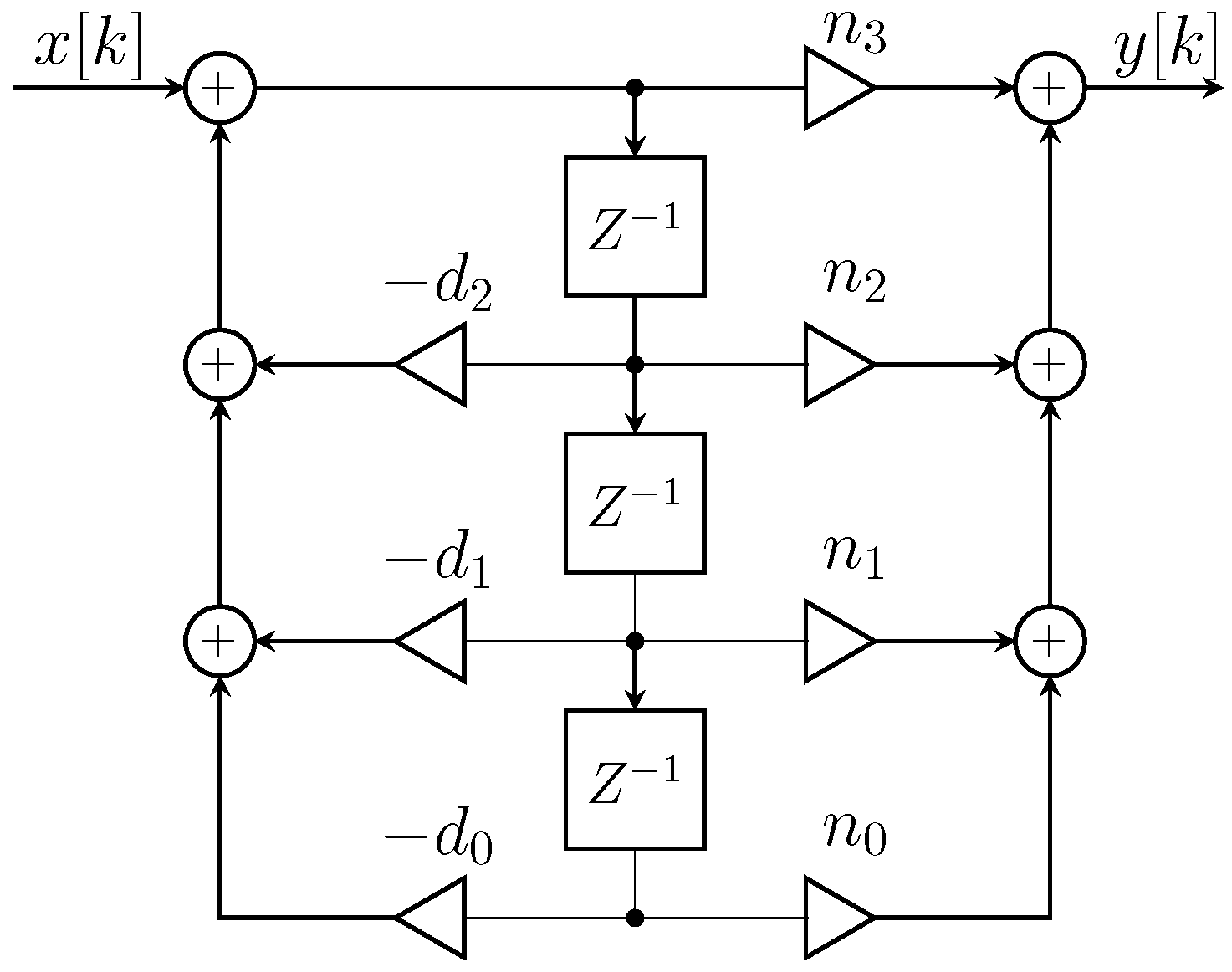
were realized using Normal Direct Form II (NDF-II) [36], as illustrated in Figure 15.
Two tests were conducted to verify the effectiveness of the proposed controller. For the first test, the load converters were sequentially connected to the DC bus such that loadB connects to the system 200 ms after LoadA. For the second test, the load converters were simultaneously connected to the DC bus.
4.3.1. Sequential Connection
Figure 16a shows the response of the system with the original controller to show its inability to handle the entire load, where and denote the output voltages of loads A and B, respectively. Connecting LoadA caused a decaying oscillatory response for 100 ms. Then, integrating loadB totally destabilized the bus voltage. As discussed earlier, the output voltages of the loads were stable.
Figure 16b shows the enhancement in the dynamic performance accomplished by the proposed controller. Connecting LoadA created oscillations in the bus voltage for 40 ms, showing 60% improvement in the settling time compared to Figure 16a. The reduction in the settling time implies that the poles of the system have moved towards the original system’s dominant poles, as shown in Figure 10. Then, connecting loadB caused negligible oscillations because the new gain margin is 4.2 dB compared to dB, as shown in Figure 11.
4.3.2. Simultaneous Testing
The effectiveness of the proposed controller to stabilize and improve the dynamic performance while connecting the two loads simultaneously is verified in this case study. Figure 17a shows connecting the two loads without the proposed modification destabilizes the bus voltage. Then, the proposed controller was implemented, and it was able to stabilize the system in 50 ms, as shown in Figure 17b, which proves the ability of the introduced method to stabilize and enhance the dynamic performance.
5. Non-Minimum Phase Cascaded System
5.1. Theoretical Analysis
Another prototype consisting of a boost converter, as the LRC, supplying a buck converter was designed, as shown in Figure 18. This prototype is studied to validate the capability of the proposed controller in controlling non-minimum phase converters. Table 2 tabulates the parameters of the system, where the source controller is (0.005 + 13.2/s) and the load controller is described by Equation (A2) in the Appendix A. The load converter was designed to supply W. However, an impedance overlap occurs, as seen in Figure 19, that destabilizes the bus voltage.
The boost converter control-to-output transfer function is described by
which has a RHP zero, and is modified to
and Equation (16) were used to shape the output impedance of the boost converter. was chosen to be rad/s because the impedance overlap occurred at rad/s, as Figure 19 depicts. As a result, the reshaped output impedance of the boost converter, using Equation (19), is shown in Figure 20, which highlights the ability of the proposed method to reshape the output impedance of the non-minimum phase converters. In addition, Figure 21 shows the unloaded loop gain (), the unstable loop gain () due to the loading impact, and the improved loop gain using the proposed controller ().
5.2. Simulation Case Studies
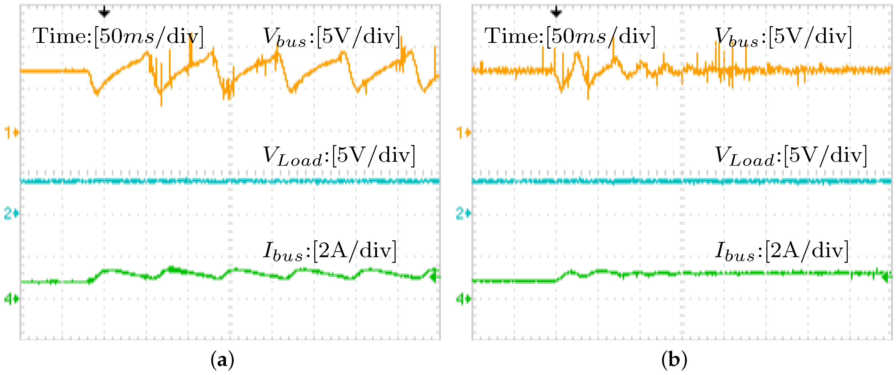
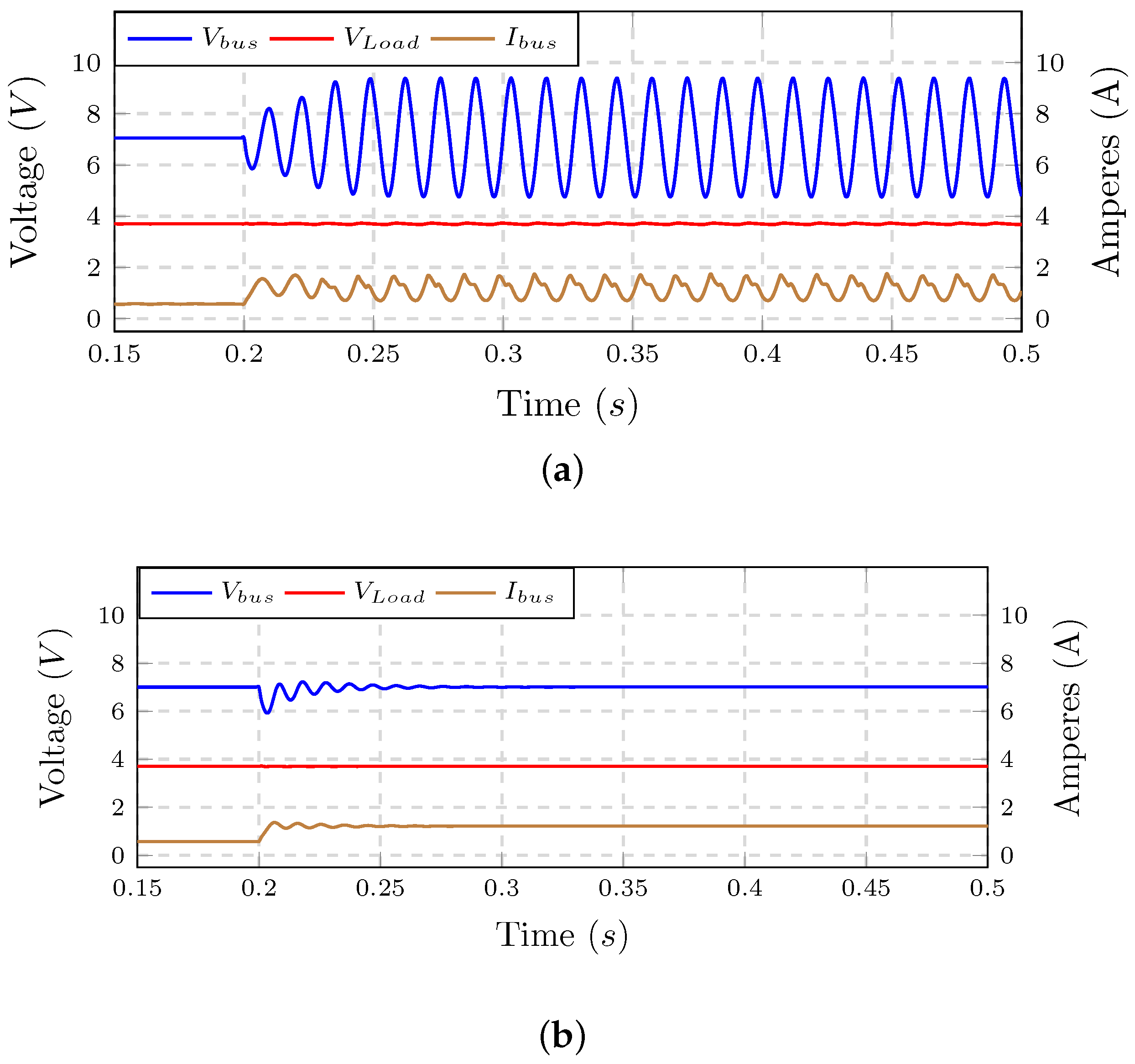
The system described in Figure 18 along with its parameters in Table 2 was simulated to verify the effectiveness of the proposed controller to stabilize a non-minimum phase converter. The test was performed by supplying of the load. Then, the remaining was connected at s. Figure 22a shows that the bus voltage has become unstable at the full load condition using the original controller.
Next the system was equipped with the proposed controller, and the test was preformed again. Adding the load at did not compromise the stability of the system. The bus voltage suffered from neither permanent oscillations nor a long settling time. Hence, the simulation validates the effectiveness of the proposed controller, and the proposed modification of to stabilize a non-minimum phase converter.
5.3. Experiment
The analytical and simulation results were further validated by experiments. A single NI-cRIO digital platform controller, with a sampling rate was of 30 kHz, was used to control the entire system of Figure 18. The digital transfer functions, such as Equation (17) were realized, as demonstrated in Figure 15.
The test was run first to demonstrate the inability of the original controller to preserve the bus voltage stability at full load condition, as shown in Figure 23a. The impact of the impedance overlap is evident. Thus, the proposed controller was implemented to decouple the impedance interaction, and the test was run again. The bus voltage stability was preserved, as Figure 23b depicts, so the experimental results are in agreement with the analytical and simulation outcomes. Collectively, these results validate the effectiveness of the proposed controller to stabilize and improve the dynamic performance of non-minimum phase converters.
6. Conclusions
This paper presents a method to stabilize and enhance the dynamic performance of cascaded DC-DC systems by reducing the magnitude of the source output impedance adaptively. The proposed controller is applicable to minimum and non-minimum phase converters that employ linearized feedback control schemes. In addition, the method can handle single or multiple loads. This flexibility is achieved by utilizing the average value of the bus current to reduce the magnitude of the source output impedance by the factor of (). The problem of reciprocating the control-to-output transfer function of DC-DC converters is solved by utilizing a low pass filter in order to realize the inversion in a certain frequency range. However, the RHP zeros of non-minimum phase converters cause instability if the corresponding transfer function is reciprocated as a result of introducing unstable poles to the system, which has been solved by mirroring the RHP zeros about the imaginary-axis of the complex plane.
Assessing the effectiveness of the controller is carried out by mathematical analysis, simulation, and experiments. All of the analyses results are in agreement and validated the satisfactory performance of the proposed control. Implementing the proposed controller could improve the relative stability margins of the studied systems. It is noteworthy that filtering the bus current introduces delay, which might prolong the settling time if the introduced delay was substantial. In addition, the discrete transfer functions are implemented practically by NDF-II, which produces the closest experimental outcomes to the simulation and to the theoretical results.
Author Contributions
The authors have participated equally in this work. Analyses, simulations, and experiments were conducted and analyzed by both of the authors.
Conflicts of Interest
The authors declare no conflict of interest.
Appendix A
References
- Luo, S. A review of distributed power systems part I: DC distributed power system. IEEE Aerosp. Electron. Syst. Mag. 2005, 20, 5–16. [Google Scholar] [CrossRef]
- Riccobono, A.; Santi, E. Comprehensive Review of Stability Criteria for DC Power Distribution Systems. IEEE Trans. Ind. Appl. 2014, 50, 3525–3535. [Google Scholar] [CrossRef]
- Yi, Z. Solar Photovoltaic (PV) Distributed Generation Systems—Control and Protection. Ph.D Thesis, The George Washington University, Washington, DC, USA, 2017. [Google Scholar]
- Ahmadi, R. Dynamic Modeling, Stability Analysis, and Controller Design for DC Distribution Systems. Ph.D Thesis, Missouri University of Science and Technology, Rolla, MO, USA, 2013. [Google Scholar]
- Muroyama, S.; Sakakibara, K.; Yamashita, T. Transient Voltage Analysis of DC Power Distribution Systems. In Proceedings of the Fifth International Telecommunications Energy Conference, 1983, INTELEC ’83, Tokyo, Japan, 18–21 October 1983; pp. 315–321. [Google Scholar]
- Emadi, A.; Ehsani, M.; Miller, J.M. Vehicular Electric Power Systems: Land, Sea, Air, and Space Vehicles; Marcel Dekker: New York, NY, USA, 2004. [Google Scholar]
- Yi, Z.; Etemadi, A.H. Line-to-Line Fault Detection for Photovoltaic Arrays Based on Multiresolution Signal Decomposition and Two-Stage Support Vector Machine. IEEE Trans. Ind. Electron. 2017, 64, 8546–8556. [Google Scholar] [CrossRef]
- Middlebrook, R.D. Input Filter Considerations in Design and Application of Switching Regulators. IEEE Ind. Appl. Soc. Annu. Meet. 1976, 11, 366–382. [Google Scholar]
- Dragicevic, T.; Lu, X.; Vasquez, J.C.; Guerrero, J.M. DC Microgrids-Part I: A Review of Control Strategies and Stabilization Techniques. IEEE Trans. Power Electron. 2016, 31, 4876–4891. [Google Scholar] [CrossRef]
- Wildrick, C.M.; Lee, F.C.; Cho, B.H.; Choi, B. A method of defining the load impedance specification for a stable distributed power system. In Proceedings of the 24th Annual IEEE Power Electronics Specialists Conference, 1993. PESC ’93 Record, Seattle, WA, USA, 20–24 June 1993; pp. 826–832. [Google Scholar]
- Feng, X.; Ye, Z.; Xing, K.; Lee, F.C.; Borojevic, D. Impedance specification and impedance improvement for DC distributed power system. In Proceedings of the 30th Annual IEEE, Power Electronics Specialists Conference (PESC 99), Charleston, SC, USA, 1 July 1999; Volume 2, pp. 889–894. [Google Scholar]
- Sudhoff, S.D.; Glover, S.F.; Lamm, P.T.; Schmucker, D.H.; Delisle, D.E. Admittance space stability analysis of power electronic systems. IEEE Trans. Aerosp. Electron. Syst. 2000, 36, 965–973. [Google Scholar] [CrossRef]
- Suntio, T. Dynamic Profile of Switched-Mode Converter: Modeling, Analysis and Control; Wiley-VCH: Weinheim, Germany, 2009. [Google Scholar]
- Wang, X.; Yao, R.; Rao, F. Three-step impedance criterion for small-signal stability analysis in two-stage DC distributed power systems. IEEE Power Electron. Lett. 2003, 1, 83–87. [Google Scholar] [CrossRef]
- Riccobono, A.; Santi, E. A novel Passivity-Based Stability Criterion (PBSC) for switching converter DC distribution systems. In Proceedings of the 2012 Twenty-Seventh Annual IEEE Applied Power Electronics Conference and Exposition (APEC), Orlando, FL, USA, 5–9 February 2012; pp. 2560–2567. [Google Scholar]
- Hankaniemi, M. Dynamical Profile of Switched-Mode Converter—Fact or Fiction? Ph.D Thesis, Tampere University of Technology, Tampere, Finland, 2007. [Google Scholar]
- Cai, W.; Yi, F.; Cosoroaba, E.; Fahimi, B. Stability Optimization Method Based on Virtual Resistor and Nonunity Voltage Feedback Loop for Cascaded DC DC Converters. IEEE Trans. Ind. Appl. 2015, 51, 4575–4583. [Google Scholar] [CrossRef]
- Wu, M.; Lu, D.D.C. A Novel Stabilization Method of LC Input Filter With Constant Power Loads Without Load Performance Compromise in DC Microgrids. IEEE Trans. Ind. Electron. 2015, 62, 4552–4562. [Google Scholar] [CrossRef]
- Zhang, X.; Ruan, X.; Zhong, Q.C. Improving the Stability of Cascaded DC/DC Converter Systems via Shaping the Input Impedance of the Load Converter With a Parallel or Series Virtual Impedance. IEEE Trans. Ind. Electron. 2015, 62, 7499–7512. [Google Scholar] [CrossRef]
- Zhang, X.; Ruan, X.; Kim, H.; Tse, C.K. Adaptive Active Capacitor Converter for Improving Stability of Cascaded DC Power Supply System. IEEE Trans. Power Electron. 2013, 28, 1807–1816. [Google Scholar] [CrossRef]
- Zhang, X.; Zhong, Q.C.; Ming, W.L. Stabilization of a Cascaded DC Converter System via Adding a Virtual Adaptive Parallel Impedance to the Input of the Load Converter. IEEE Trans. Power Electron. 2016, 31, 1826–1832. [Google Scholar] [CrossRef]
- Ahmadi, R.; Ferdowsi, M. Improving the Performance of a Line Regulating Converter in a Converter-Dominated DC Microgrid System. IEEE Trans. Smart Grid 2014, 5, 2553–2563. [Google Scholar] [CrossRef]
- Ahmadi, R.; Ferdowsi, M. Controller design method for a cascaded converter system comprised of two DC-DC converters considering the effects of mutual interactions. In Proceedings of the 2012 Twenty-Seventh Annual IEEE Applied Power Electronics Conference and Exposition (APEC), Orlando, FL, USA, 5–9 February 2012; pp. 1838–1844. [Google Scholar]
- Erickson, R.W.; Dragan, M. Fundamentals of Power Electronics; Kluwer Academic: Norwell, MA, USA, 2001. [Google Scholar]
- Basso, C.P. Designing Control Loops for Linear and Switching Power Supplies: A Tutorial Guide; Artech House: Norwood, MA, USA, 2012. [Google Scholar]
- Ang, S.S. Power-Switching Converters; M. Dekker: New York, NY, USA, 1995. [Google Scholar]
- Ahmadi, R.; Paschedag, D.; Ferdowsi, M. Analyzing stability issues in a cascaded converter system comprised of two voltage-mode controlled dc-dc converters. In Proceedings of the 2011 Twenty-Sixth Annual IEEE, Applied Power Electronics Conference and Exposition (APEC), Fort Worth, TX, USA, 6–11 March 2011; pp. 1769–1775. [Google Scholar]
- Wildrick, C.M. Stability of Distributed Power Supply Systems. Ph.D Thesis, Virginia Polytechnic and State University, Blacksburg, VA, USA, 1993. [Google Scholar]
- Pidaparthy, S.K.; Choi, B. Stability analysis of PWM converters connected to general load subsystems. In Proceedings of the 2015 9th International Conference on Power Electronics and ECCE Asia (ICPE-ECCE Asia), Seoul, Korea, 1–5 June 2015; pp. 1033–1040. [Google Scholar]
- Cao, L.; Loo, K.H.; Lai, Y.M. Systematic Derivation of a Family of Output-Impedance Shaping Methods for Power Converters—A Case Study Using Fuel Cell-Battery-Powered Single-Phase Inverter System. IEEE Trans. Power Electron. 2015, 30, 5854–5869. [Google Scholar] [CrossRef]
- Cao, L.; Loo, K.H.; Lai, Y.M. Output-Impedance Shaping of Bidirectional DAB DC - DC Converter Using Double-Proportional-Integral Feedback for Near-Ripple-Free DC Bus Voltage Regulation in Renewable Energy Systems. IEEE Trans. Power Electron. 2016, 31, 2187–2199. [Google Scholar] [CrossRef]
- Aldhaheri, A.; Etemadi, A. Impedance Decoupling in DC Distributed Systems to Maintain Stability and Dynamic Performance. Energies 2017, 10, 470. [Google Scholar] [CrossRef]
- Braatz, R.D. On Internal Stability and Unstable Pole-Zero Cancellations [Feedback]. IEEE Control Syst. 2012, 32, 15–16. [Google Scholar] [CrossRef]
- Nise, N.S. Control Systems Engineering, Binder Version; John Wiley & Sons Inc.: Hoboken, NJ, USA, 2010. [Google Scholar]
- Sudhoff, S.D.; Corzine, K.A.; Glover, S.F.; Hegner, H.J.; Robey, H.N. DC link stabilized field oriented control of electric propulsion systems. IEEE Trans. Energy Conver. 1998, 13, 27–33. [Google Scholar] [CrossRef]
- Manolakis, D.G.; Ingle, V.K. Applied Digital Signal Processing: Theory and Practice; Cambridge University Press: Cambridge, UK, 2011. [Google Scholar]
Figure 1.
Cascaded DC-DC system.
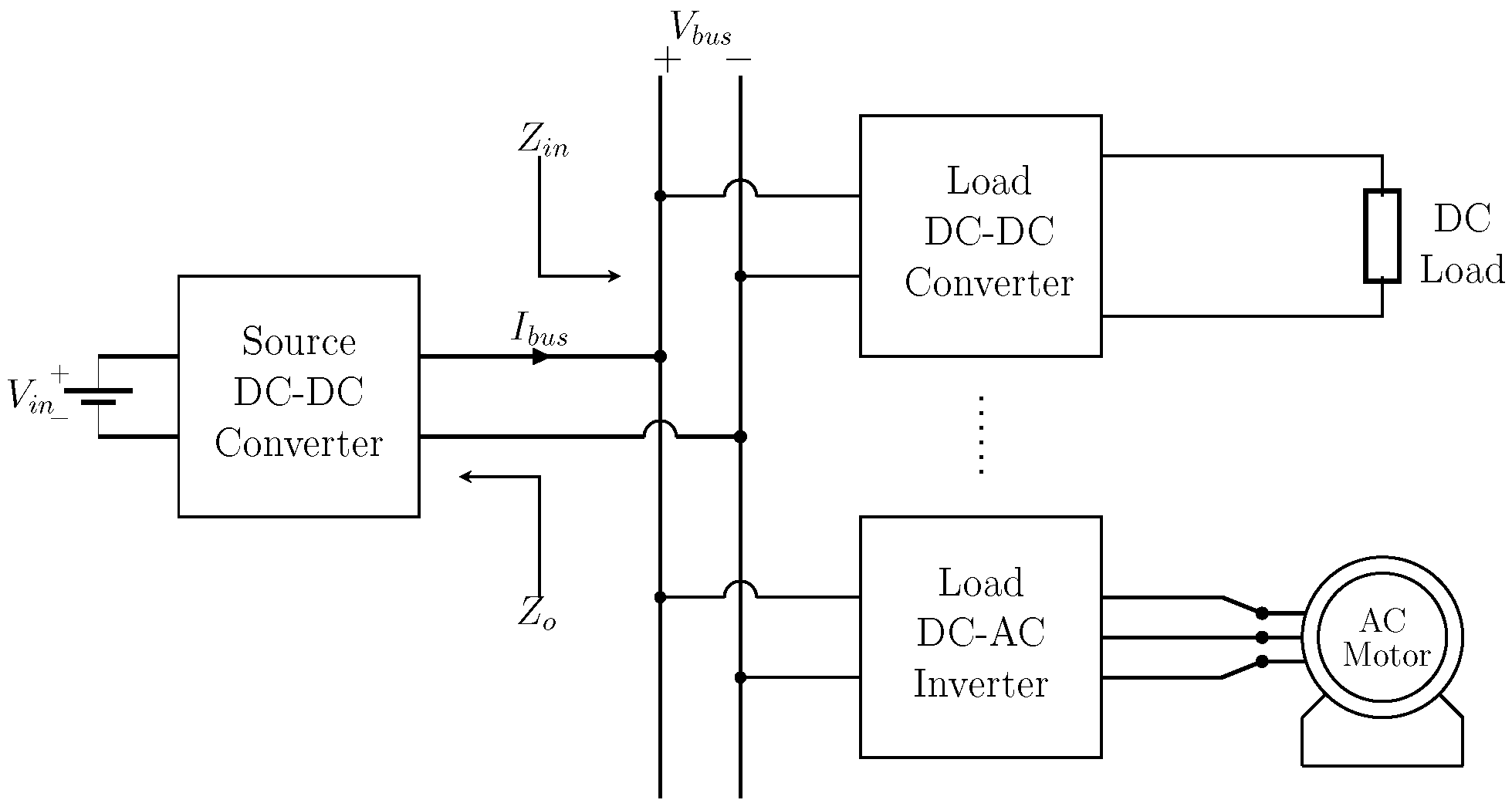
Figure 2.
Typical source and load impedances of Figure 1, highlighting their interaction around .
Figure 2.
Typical source and load impedances of Figure 1, highlighting their interaction around .

Figure 3.
Closed-loop LRC using the proposed modifications in [30,31], where their additions to the original control are highlighted in red.
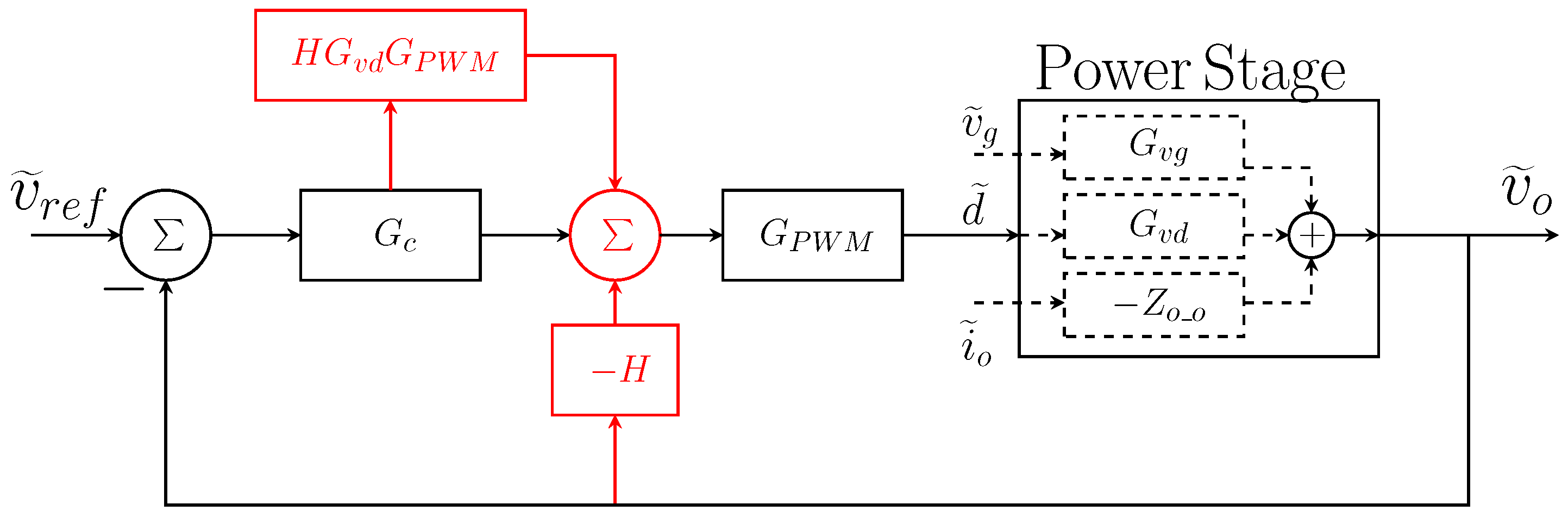
Figure 4.
Reshaping of source output impedance, where represents that of the original controller, and is the reshaped impedance for the proposed controller with in Equation (12) and rad/s.
Figure 4.
Reshaping of source output impedance, where represents that of the original controller, and is the reshaped impedance for the proposed controller with in Equation (12) and rad/s.
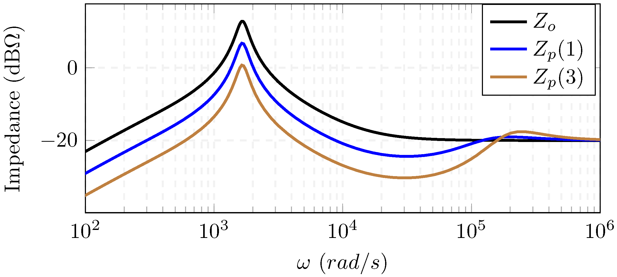
Figure 5.
The proposed controller for the line regulating converter, where modifications to original controller are highlighted in red.
Figure 5.
The proposed controller for the line regulating converter, where modifications to original controller are highlighted in red.

Figure 6.
Experimental setup schematic diagram.

Figure 7.
Impedance interaction for the experimental system, for the original controller, with two different loading conditions.
Figure 7.
Impedance interaction for the experimental system, for the original controller, with two different loading conditions.
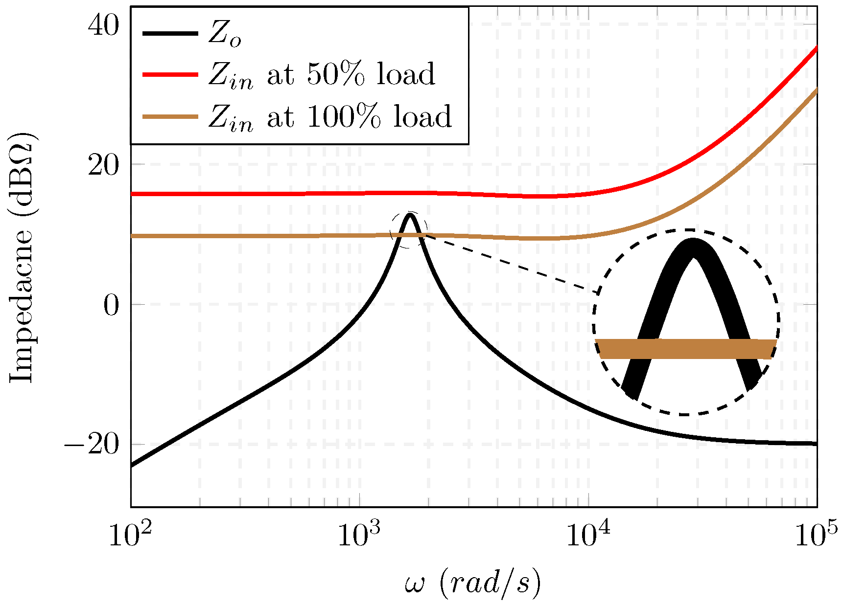
Figure 8.
Nyquist diagram of the LRC loop gain () for the original controller for three loading conditions, where it encircles at 100% loading.
Figure 8.
Nyquist diagram of the LRC loop gain () for the original controller for three loading conditions, where it encircles at 100% loading.
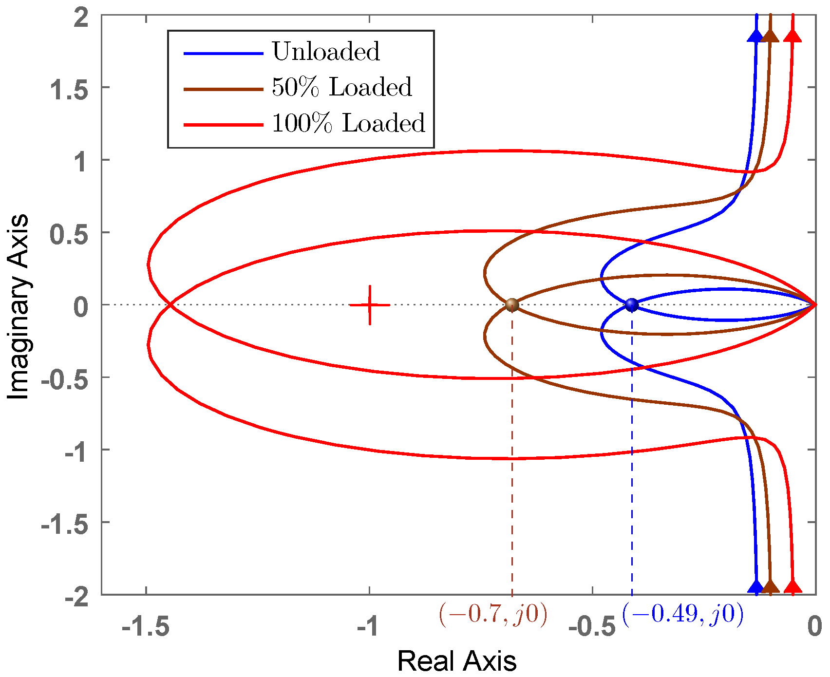
Figure 9.
Comparison between original and proposed output impedances of the LRC, highlighting the capability of the proposed controller in removing the interaction.
Figure 9.
Comparison between original and proposed output impedances of the LRC, highlighting the capability of the proposed controller in removing the interaction.
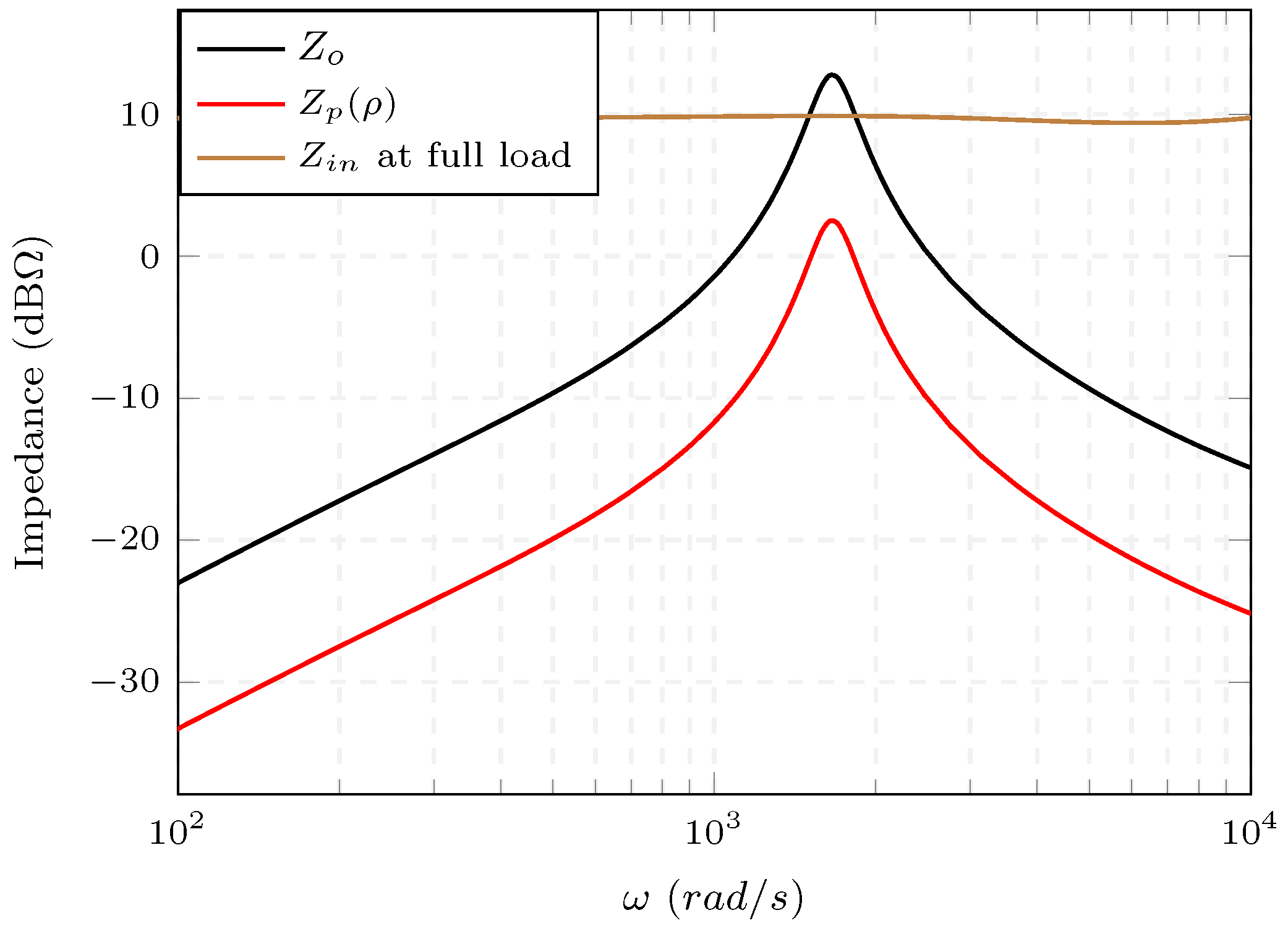
Figure 10.
Pole loci of the closed loop LRC, for unstable system with the original control at full load (black poles), original control at no load (red poles), and proposed control (blue poles), highlighting the decoupling capability, as a function of .
Figure 10.
Pole loci of the closed loop LRC, for unstable system with the original control at full load (black poles), original control at no load (red poles), and proposed control (blue poles), highlighting the decoupling capability, as a function of .
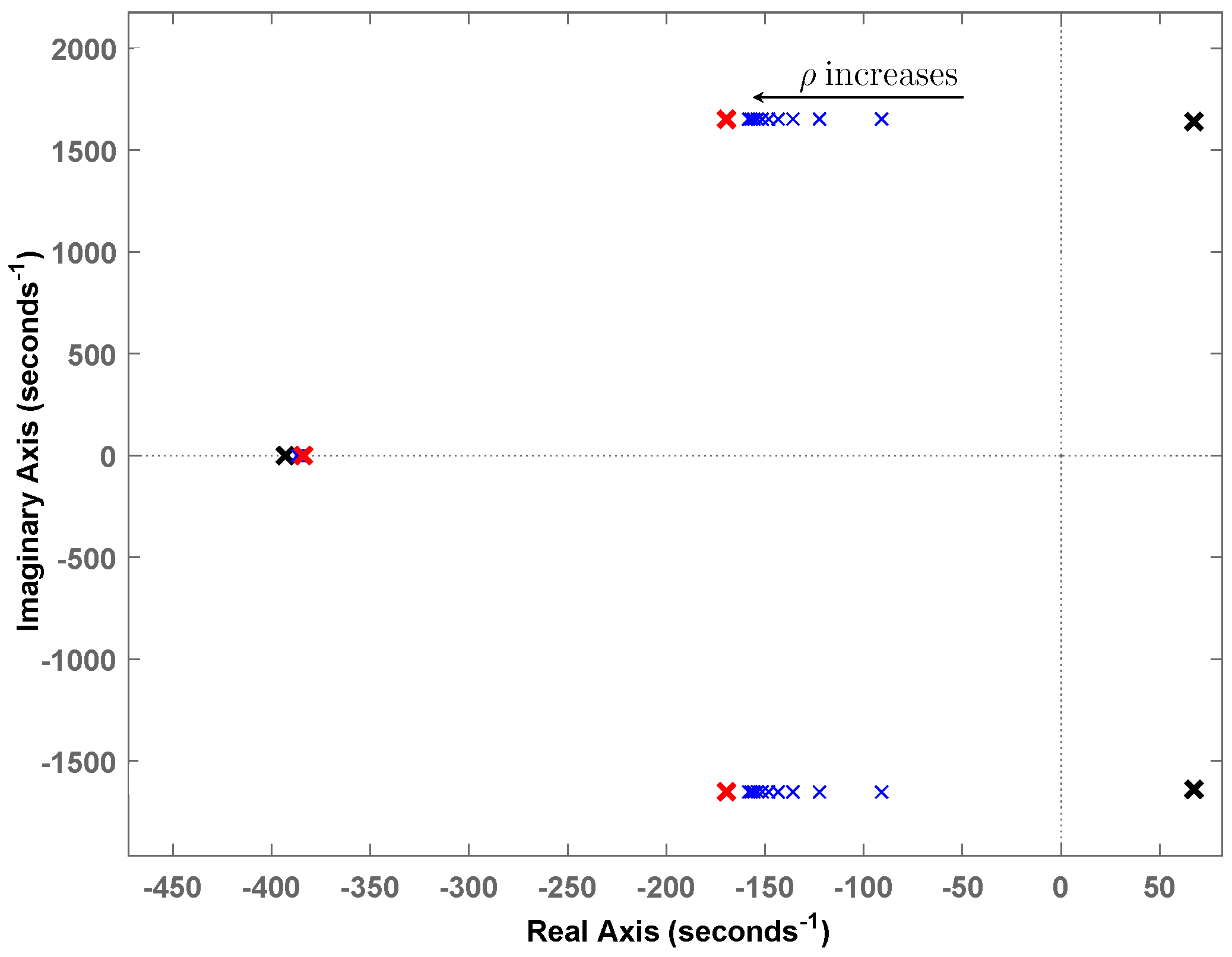
Figure 11.
Comparing the Nyquist diagrams of LRC’s loop gain at full load with and without the proposed controller, highlighting its stabilizing and performance preserving capability.
Figure 11.
Comparing the Nyquist diagrams of LRC’s loop gain at full load with and without the proposed controller, highlighting its stabilizing and performance preserving capability.
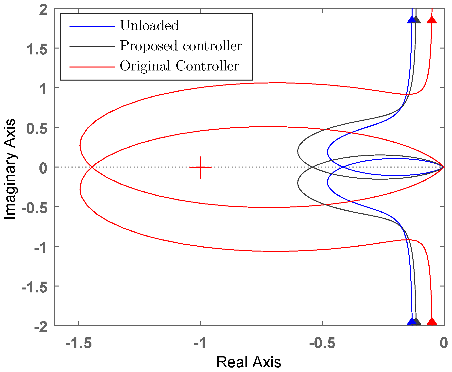
Figure 12.
Simulation results for sequential switchings of LoadA (at s) and LoadB (at s): (a) without the proposed control; and (b) with the proposed control.
Figure 12.
Simulation results for sequential switchings of LoadA (at s) and LoadB (at s): (a) without the proposed control; and (b) with the proposed control.

Figure 13.
Simulation results for sequential switchings of LoadA and LoadB (at s): (a) without the proposed control; and (b) with the proposed control.
Figure 13.
Simulation results for sequential switchings of LoadA and LoadB (at s): (a) without the proposed control; and (b) with the proposed control.
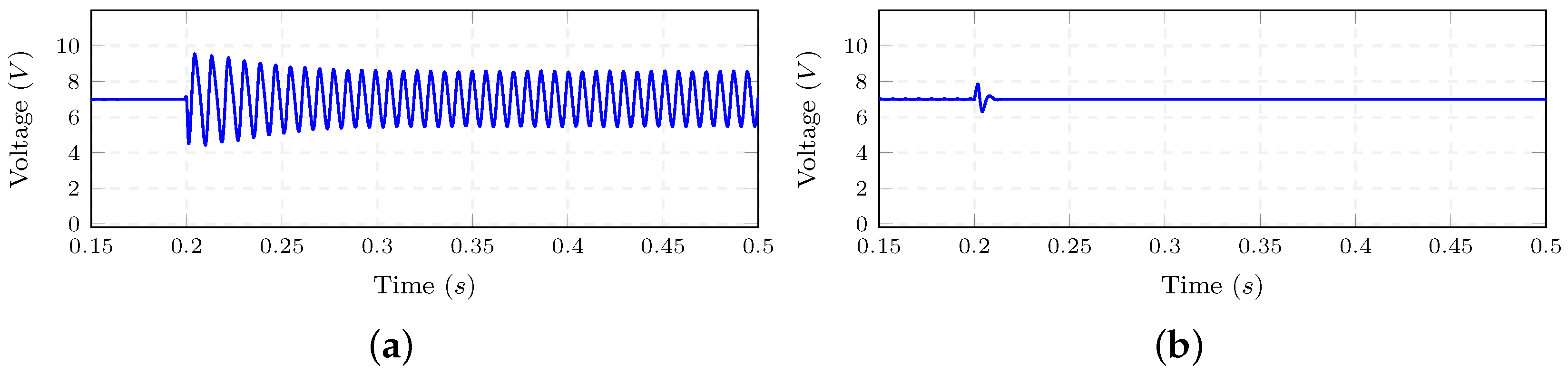
Figure 14.
The experimental setup.
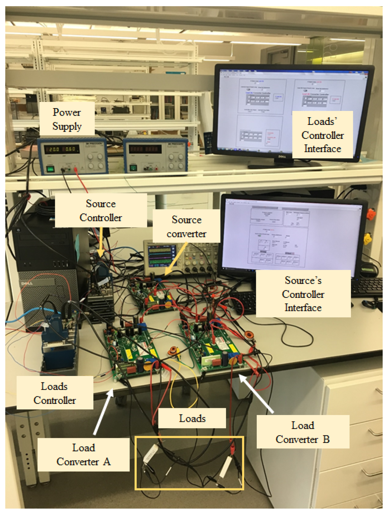
Figure 15.
Normal Direct Form-II realization of the discrete transfer function of Equation (17).
Figure 15.
Normal Direct Form-II realization of the discrete transfer function of Equation (17).

Figure 16.
Experimental results of sequential switching of LoadA and LoadB: (a) without the proposed controller; and (b) with the proposed controller.
Figure 16.
Experimental results of sequential switching of LoadA and LoadB: (a) without the proposed controller; and (b) with the proposed controller.
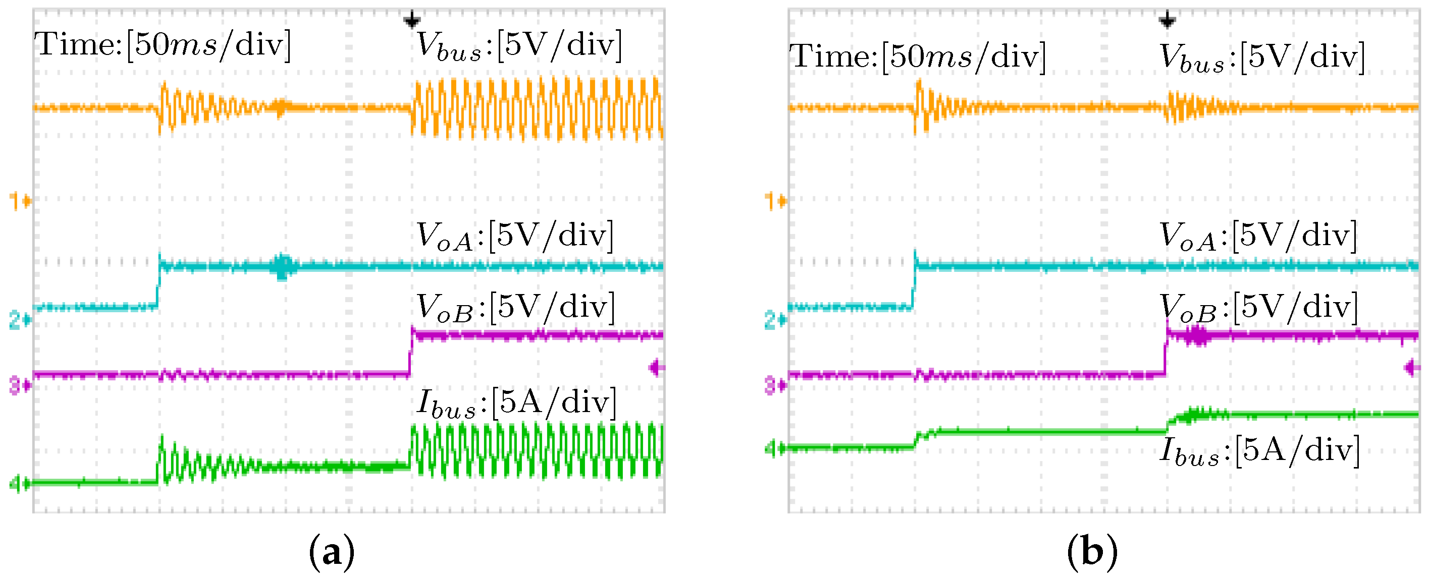
Figure 17.
Experimental results of simultaneous switching of LoadA and LoadB: (a) without the proposed controller; and (b) with the proposed controller.
Figure 17.
Experimental results of simultaneous switching of LoadA and LoadB: (a) without the proposed controller; and (b) with the proposed controller.
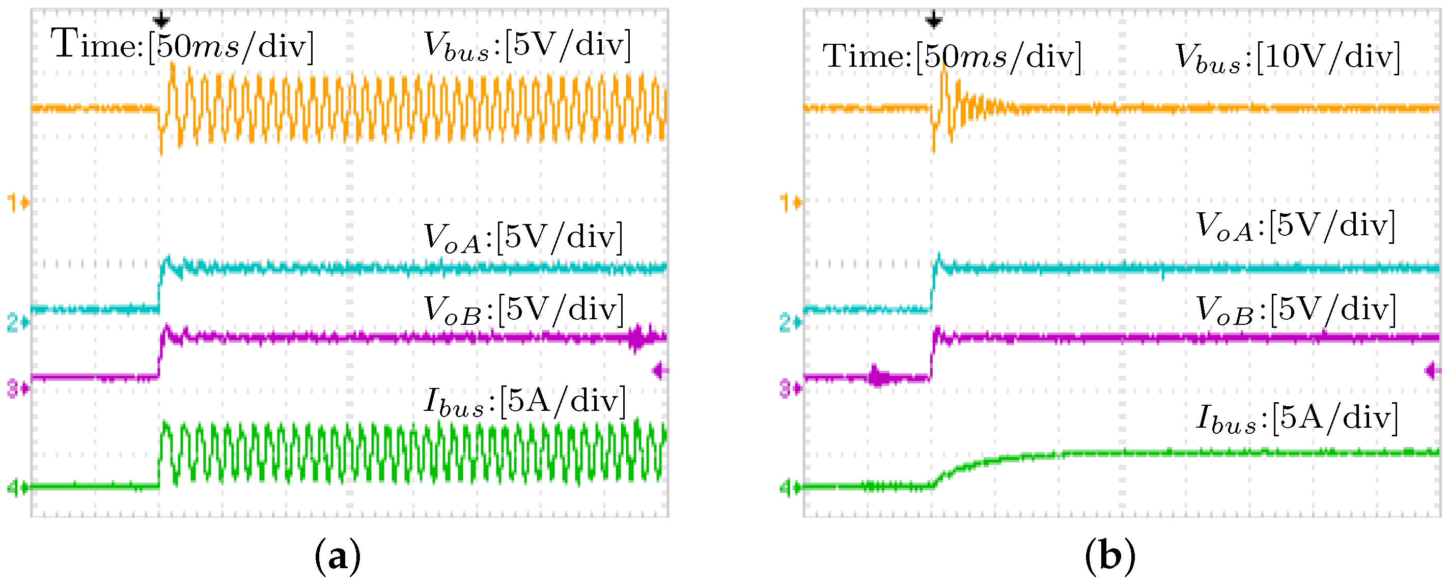
Figure 18.
Cascaded system with a boost converter as the LRC.
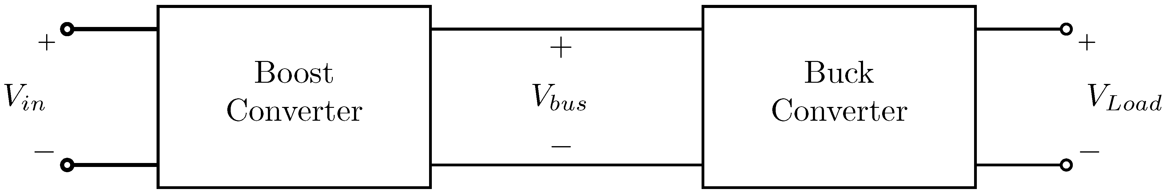
Figure 19.
Impedance interaction between the boost and the buck converters.
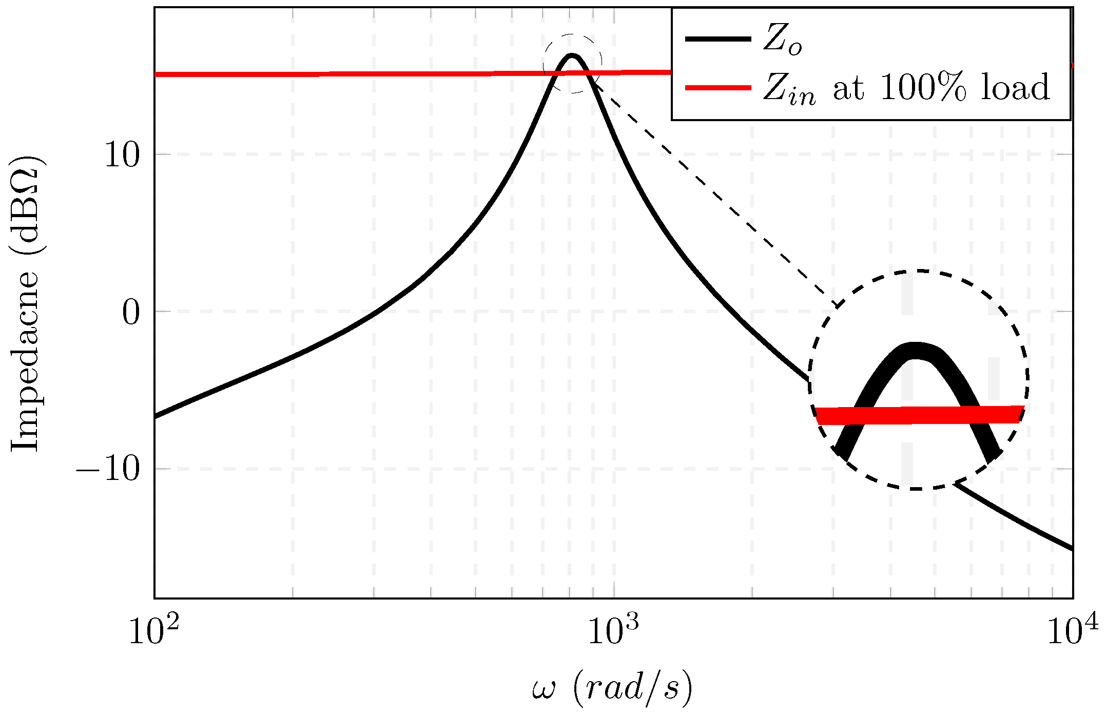
Figure 20.
Impedance interaction decoupling between the boost and the buck converters using the proposed method.
Figure 20.
Impedance interaction decoupling between the boost and the buck converters using the proposed method.
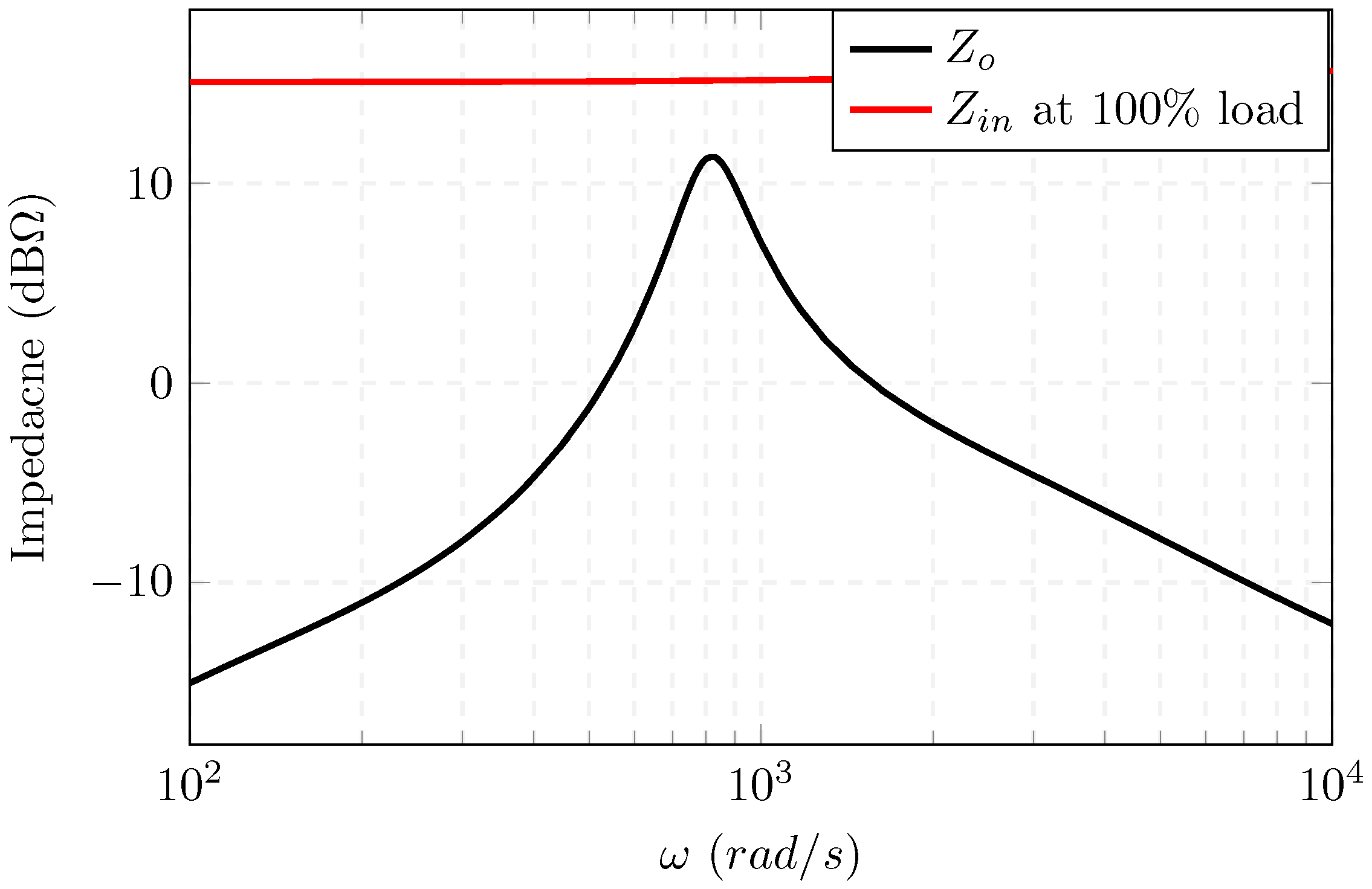
Figure 21.
The unloaded, improved, and unstable loop gains of the source converter, depicting the ability of the proposed controller to stabilized the non-minimum phase systems.
Figure 21.
The unloaded, improved, and unstable loop gains of the source converter, depicting the ability of the proposed controller to stabilized the non-minimum phase systems.

Figure 22.
The dynamic performance of the boost-driven cascaded system: (a) without the proposed controller; and (b) with the proposed controller.
Figure 22.
The dynamic performance of the boost-driven cascaded system: (a) without the proposed controller; and (b) with the proposed controller.

Figure 23.
Experimental results the boost-driven cascaded system: (a) without the proposed controller; and (b) with the proposed controller.
Figure 23.
Experimental results the boost-driven cascaded system: (a) without the proposed controller; and (b) with the proposed controller.

Table 1.
Numerical parameters of the test system.
| Parameter | Source | Load A | Load B |
|---|---|---|---|
| 20 | 7 | 7 | |
| 7 | 4 | 4 | |
| 510 | 390 | 400 | |
| 0.05 | 0.01 | 0.04 | |
| 697 | 697 | 697 | |
| 0.1 | 0.1 | 0.1 | |
| ⋯ | 2 | 2 | |
| 100 | |||
| 1 | |||
| Source Controller | |||
Table 2.
Numerical parameters of the test system in Figure 18.
Table 2.
Numerical parameters of the test system in Figure 18.
| Parameter | Boost | Buck |
|---|---|---|
| 5 | 7 | |
| 7 | 3.6 | |
| 930 | 390 | |
| 0.05 | 0.01 | |
| 697 | 697 | |
| 0.1 | 0.1 | |
| ⋯ | 1.4 | |
| 100 | ||
| 1 | ||
© 2018 by the authors. Licensee MDPI, Basel, Switzerland. This article is an open access article distributed under the terms and conditions of the Creative Commons Attribution (CC BY) license (http://creativecommons.org/licenses/by/4.0/).
Share and Cite
MDPI and ACS Style
Aldhaheri, A.; Etemadi, A. Adaptive Stabilization and Dynamic Performance Preservation of Cascaded DC-DC Systems by Incorporating Low Pass Filters. Energies 2018, 11, 440. https://doi.org/10.3390/en11020440
AMA Style
Aldhaheri A, Etemadi A. Adaptive Stabilization and Dynamic Performance Preservation of Cascaded DC-DC Systems by Incorporating Low Pass Filters. Energies. 2018; 11(2):440. https://doi.org/10.3390/en11020440
Chicago/Turabian StyleAldhaheri, Ahmed, and Amir Etemadi. 2018. "Adaptive Stabilization and Dynamic Performance Preservation of Cascaded DC-DC Systems by Incorporating Low Pass Filters" Energies 11, no. 2: 440. https://doi.org/10.3390/en11020440
Note that from the first issue of 2016, this journal uses article numbers instead of page numbers. See further details here.