1. Introduction
Due to the growing demand for energy, increased fuel prices, and severe air pollution restrictions in the road transport sector, all nations are vigorously developing and finding alternative fuel sources and new technologies in order to reduce the dependency on fossil fuels. Recently, attention has been drawn to cleaner alternative fuels from renewable sources and to improve fuel cell vehicles, in order to reduce the harmful emission in city centers, and to decrease the need of fossil fuels, which are worldwide issues [
1,
2].
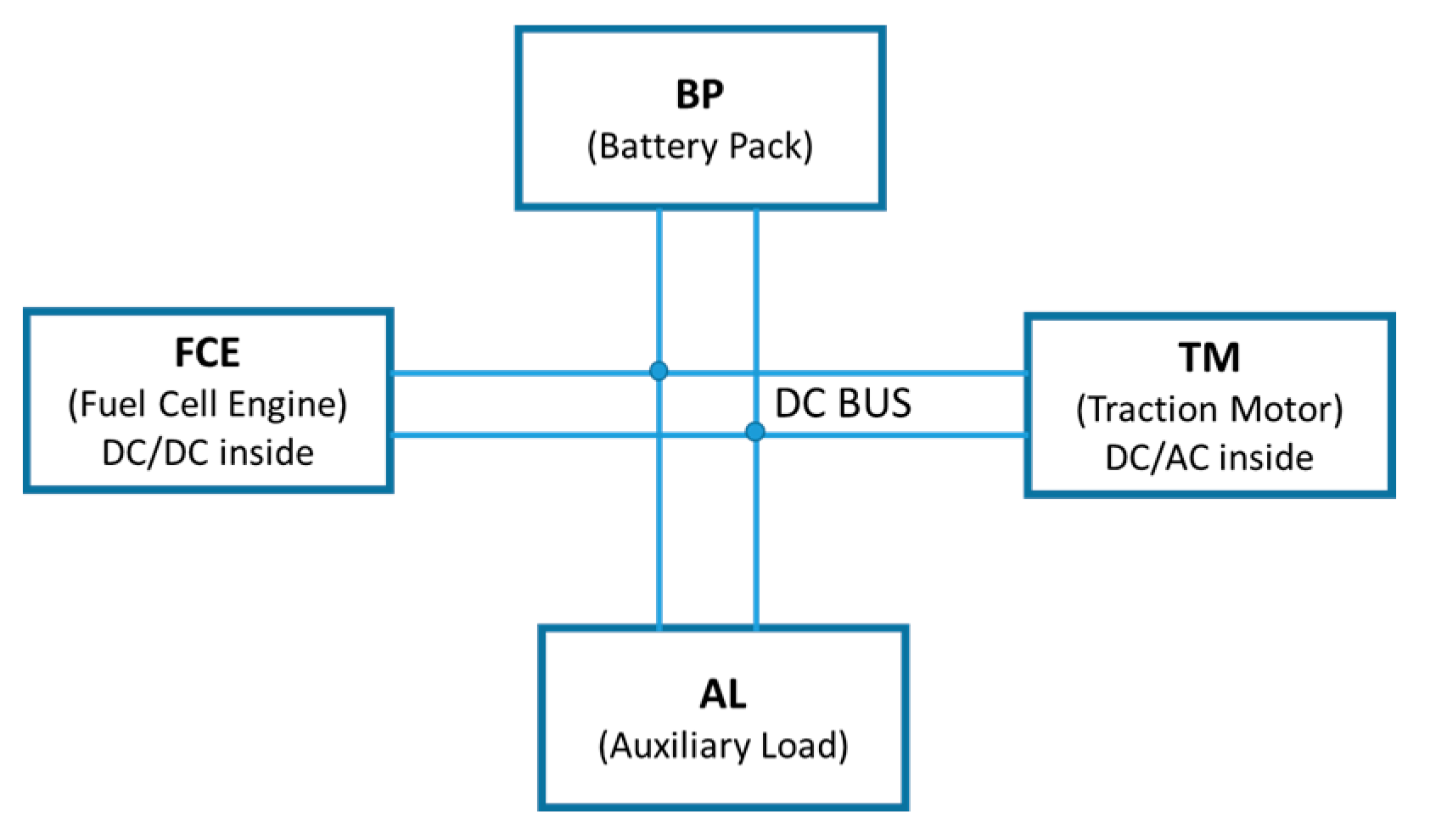
Fuel cell vehicles have long-term potential as future mainstream vehicles because of their high efficiency and zero emission characteristics. The powertrain of fuel cell vehicles generally has three main subsystems in the hybrid system architecture: the fuel cell engine (FCE), the energy storage unit (ESU), and the traction motor (TM). In this paper, a battery pack (BP) is used as the ESU part in
Figure 1.
Hybridization of fuel cell vehicles with a storable battery has many benefits. Fuel cells have a slow transient response to overcome, and have a specified warm-up time to reach the expected power output. Moreover, auxiliaries of fuel cell systems need power supplies during system start-up. Hybridization of the fuel cell vehicle powertrain system can overcome the above issues and increase the efficiency by utilizing regenerative breaking energy, and the cost by pure fuel cell power sizing is reduced as well. The hybrid degree of the fuel cell vehicle is the first and key issue for the powertrain system design.
There is a basic powertrain system research procedure [
3,
4]: the first step is to decide the system architecture with model simulation technology, then put the physical parts into a dynamometer environment for evaluation and model identification. The final step is to design and verify the vehicle control strategy. Generally, the hybrid degree is defined as the ratio of the electric power that can be delivered by the ESU to the total power that can be delivered by the ESU and FCE [
5], which is used for the powertrain sizing definition with the considerations of economics and cost performance [
6,
7,
8]. Some papers present the hybrid degree in the powertrain control research [
9,
10]. If taking the whole tank of hydrogen and the battery pack as separate power resources with specific power capacities, the purpose for hybrid degree research is to meet the longest driving distance and the most dynamic vehicle requirements. Thus, the vehicle dynamic requirement changes all the time, the hybrid degree should be a dynamic definition, and the boundary is related to the powertrain system architecture. Powertrain system research should be a systematical engineering study. The architecture needs to serve the vehicle design requirements, and the control strategy needs to work under the architecture constraints to achieve the specified targets of dynamic performance and economic performance.
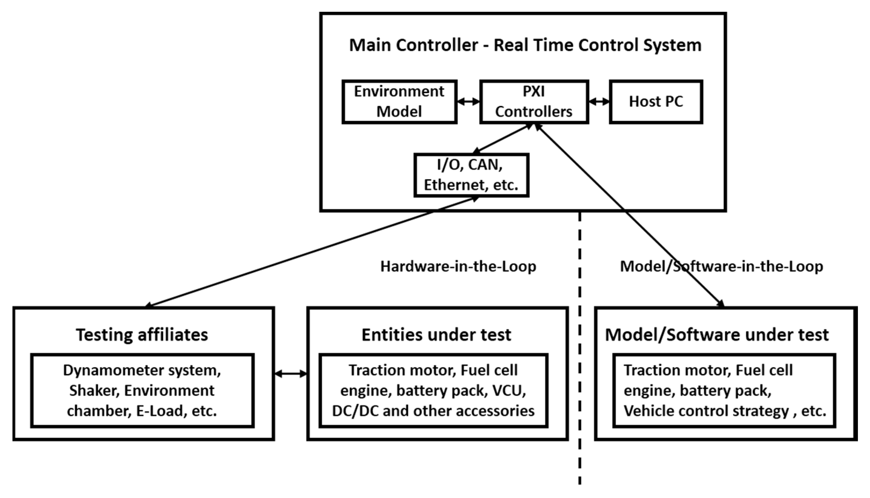
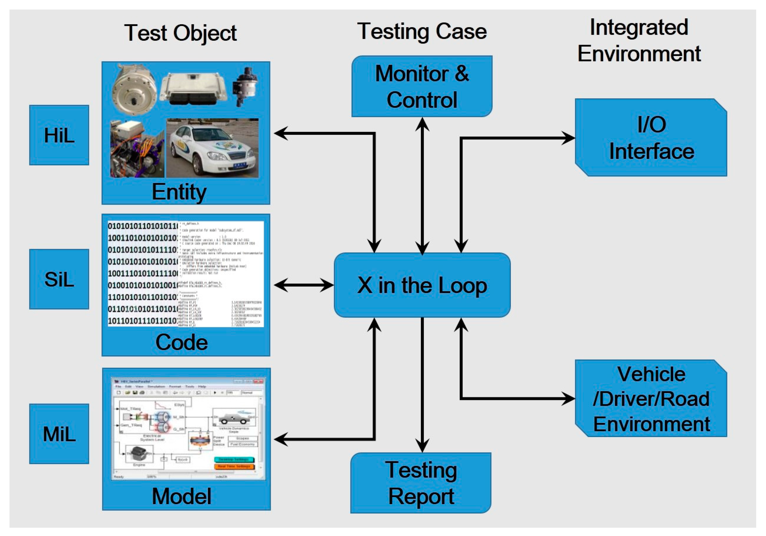
Recently, the pressure to reduce the development time and to develop more reliable powertrain systems before road testing has rapidly increased in the automotive industry. Under such circumstances, model-based development processes and closed-loop environment simulation technology have been widely used and have brought very successful results [
11,
12,
13]. X-in-the-Loop (XiL) is an integrated in-loop method, and the concept was first proposed by Professor Albers from KIT, Germany [
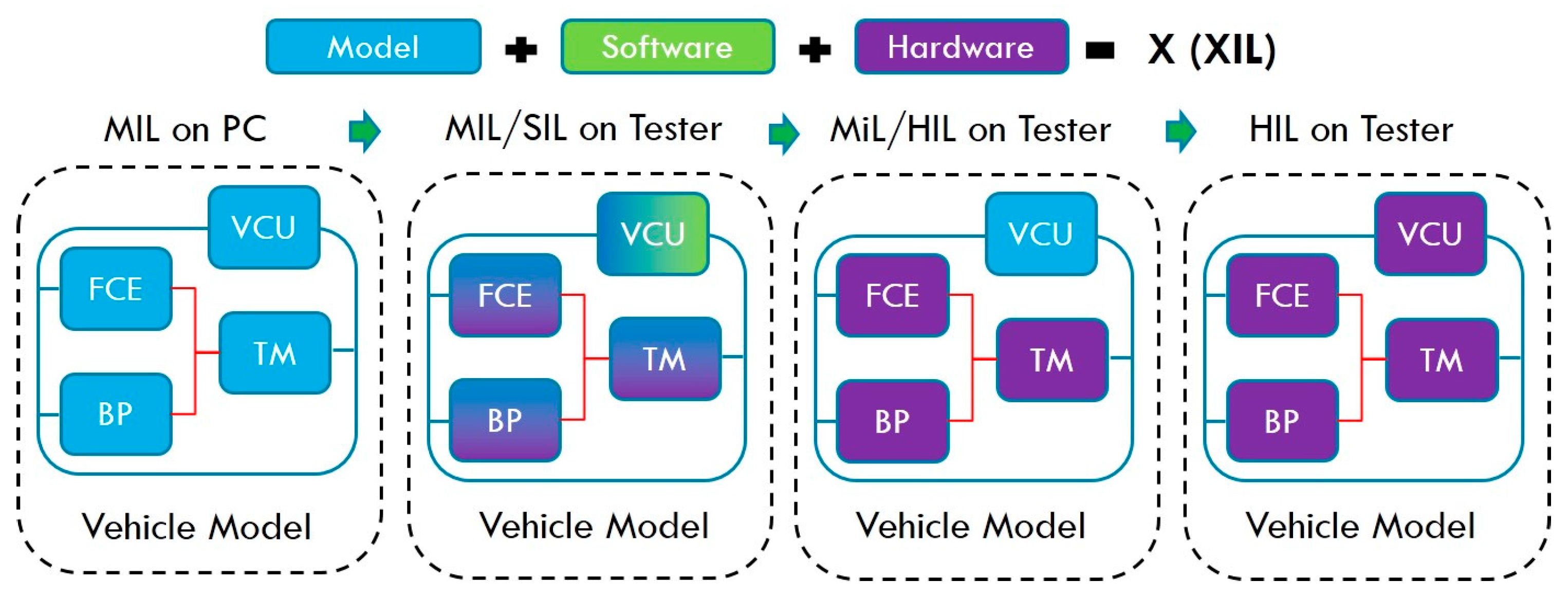
14]. Where X refers to the unit under test, which can be a model (model in the loop, MiL), software (software in the loop, SiL), and hardware (hardware in the loop, HiL) [
15]. MiL, SiL, and HiL are originally the testing methods during the process of vehicle ECU development in the traditional sense, usually used in different developing stages of the ECU. In this paper, the traditional definitions of MiL, SiL, and HiL have been expanded as shown in
Figure 2. MiL refers to, in a complete test cycle, the tested object existing in the form of model, while other parts of the testing components are hardware or entities. SiL refers to, in a complete test cycle, the tested object existing in the form of code, while other parts of the testing components are hardware or entities. HiL refers to, in a complete test cycle, the tested object existing in the form of hardware, and other parts of the testing components are hardware or entities, not only referring to the condition that the tested object is the controller entity. This work is based on the project ‘The integrated testing platform development and application of FCV powertrain system dynamic performance’, which is supported by the Chinese Ministry of Science and Technology. In this paper, XiL will be applied tothe hybrid degree testing from the powertrain system architecture and components sizing determination to the control strategy testing and powertrain system validation.
2. Hybrid Degree Test Process and Scenarios Design
Based on the principle of XiL technology, the importance and the meaning of the hybrid degree of fuel cell vehicle, a novel and completed hybrid degree testing method with test process and scenarios was introduced in the
Figure 3.
The testing begins from MiL on a PC, so that the model will be running on the PC environment without a real-time requirement for function evaluation. Then MiL and SiL testing will be implemented on the tester, which is the real-time platform, model, or software code is the unit under test, the testing purpose is to verify the system architecture and sizing of the key components. After this, the hardware entities of the FCE, battery pack, and traction motor will be presented one by one in the Hardware-in-the-Loop testing, the VCU (vehicle control unit) control strategy model will be verified in the tester’s real-time hardware, and MiL testing will be fulfilled. Finally the VCU, FCE, battery pack, and traction motor physical entities, as the hardware of powertrain system, will be tested under HiL circumstances. The testing target of hybrid degree testing based on XiL technology was shown in
Table 1.
3. Hybrid Degree Re-Definition and Research
3.1. Hybrid Degree Re-Defination
In this paper, hybrid degree is divided into static hybrid degree (
) and dynamic hybrid degree (
).
is defined for powertrain architecture research, and
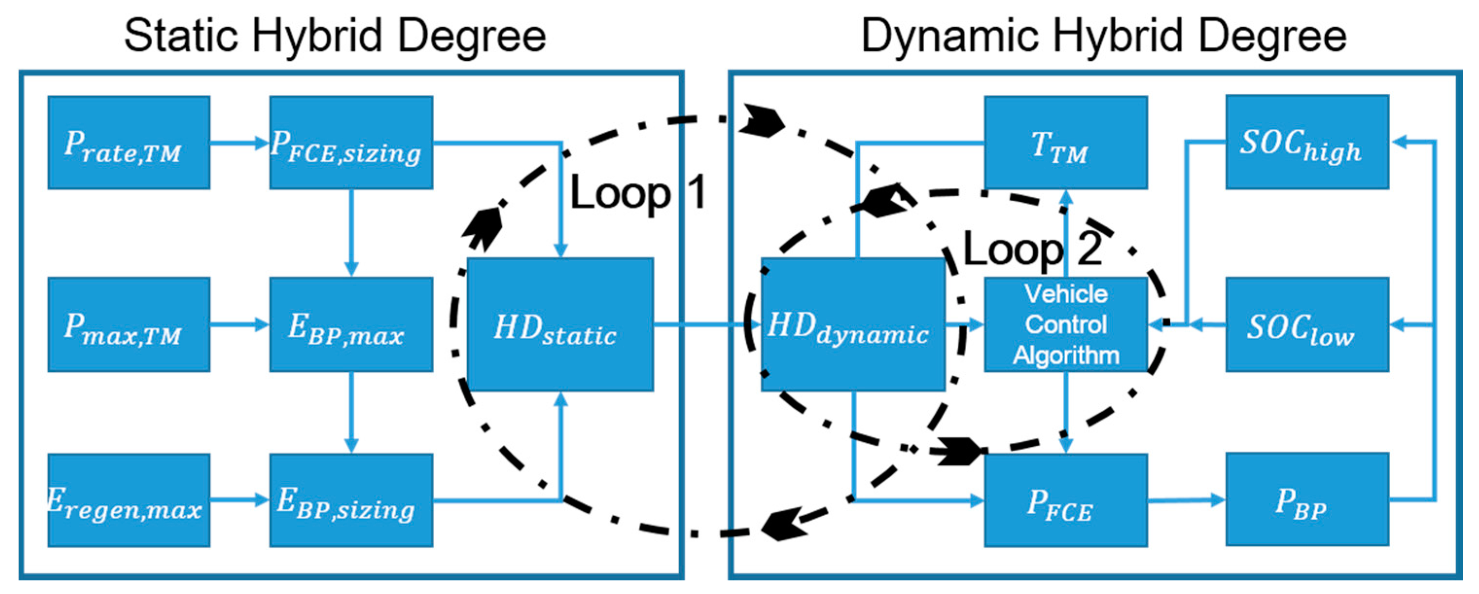
is defined for powertrain energy control strategy research. With the re-definition of the hybrid degree, a system of powertrain system design and testing is shown in the
Figure 4.
: Rated power of traction motor;
: FCE sizing power;
: Maximum traction motor power;
Battery pack allowed frequent working energy capacity;
: Maximum reserved energy capacity for regeneration in one time.;
: Battery pack sizing energy capacity;
: Target torque of traction motor;
: Target power output of FCE;
: Power output of battery pack;
The low threshold of state of charge; and
The high threshold of state of charge.
Two loops are formed for design evaluation and optimization; loop 1 is used for the system architecture and subsystem sizing, and loop 2 is based on the loop 1, used for the vehicle control algorithm design, and can also help to update the static hybrid degree design. According to the production development of fuel cell, the cost will be dropped dramatically in the last five years and in the near future [
16,
17], so the cost factor is not considered for the hybrid degree optimization. Hybrid degree design will be analyzed from energy efficiency view under the vehicle dynamic request:
Here is the battery pack dynamic output power, and is the FCE dynamic output power. The continuously optimized behavior is to control the traction motor and FCE dynamic output inside the static sizing boundary of three key parts of the powertrain system.
3.2. Traction Motor Sizing
Traction motor sizing determination is related to the vehicle specification, and is also to give the dynamic requirement for the FCE and battery pack design. The following equation can be used to define the drive load on the traction motor:
Here, is the traction motor power, is the friction resistance, is the air resistance, is the gradient resistance, is the acceleration resistance, u is the vehicle speed, is the TM torque, is the TM speed, is the maximum TM power, is the maximum power for vehicle resistance on the max gradient, is the maximum power for vehicle resistance on the maximum acceleration, is the maximum power for vehicle resistance on the max speed, and is the traction motor efficiency.
Now the basic required power and torque to the traction motor by the vehicle specification are calculated. Then the motor sizing is decided under below condition:
High efficiency zone is in the high frequency working point, and permanent magnet (PM) motor is preferred with smaller size and high efficiency. The torque of the motor is higher than the required torque by vehicle specification at any valid working point (vehicle speed range). Other conditions should be considered, like physic deploy, bus voltage. With the specification of chose motor, the maximum current curve under vehicle requirement can be obtained, which will be used to optimize the battery and fuel cell engine sizing.
3.3. Constraint Due to Dynamic Design Target
Fuel cell engine can’t work as high frequent power resource to meet the vehicle load change, so here to take FCE as low frequency power resource, to take battery pack as a high-frequency power resource.
Basically, the powertrain system must meet the three dynamic indices under max acceleration, maximum grade, and the highest speed condition. Thus, it will be reasonable to define the FCE power sizing parameter to be no less than the minimum power designed for continuously highest speed (
), or it will drain out the battery energy and slow down the speed for a long driving:
Therefore, the maximum power of the battery is determined, i.e.:
This can be used as a basic principal for the sizing design of the fuel cell system, and be flexible for specified application. For example, the specific daily driving distance allows using a smaller sizing fuel cell system with a larger energy battery pack for a plug-in FC bus.
3.4. Constraint Due to Fuel Cell System Efficiency
The hybrid degree design is observed in the hybrid system from the energy point of view—electric work and mechanical work—so that the mechanical work of the vehicle from beginning to the end of the drive cycle equals the production by electric work and the transformation efficiency. Electric work of the traction motor equals the energy production (from the fuel cell engine and battery pack) and transformation efficiency:
: Work of the vehicle;
: Work of the traction motor;
: Transformation efficiency from the electric work of the traction motor to vehicle mechanical work;
: Transformation efficiency from hydrogen to power output by FCE; and
: Transformation efficiency for the battery pack.
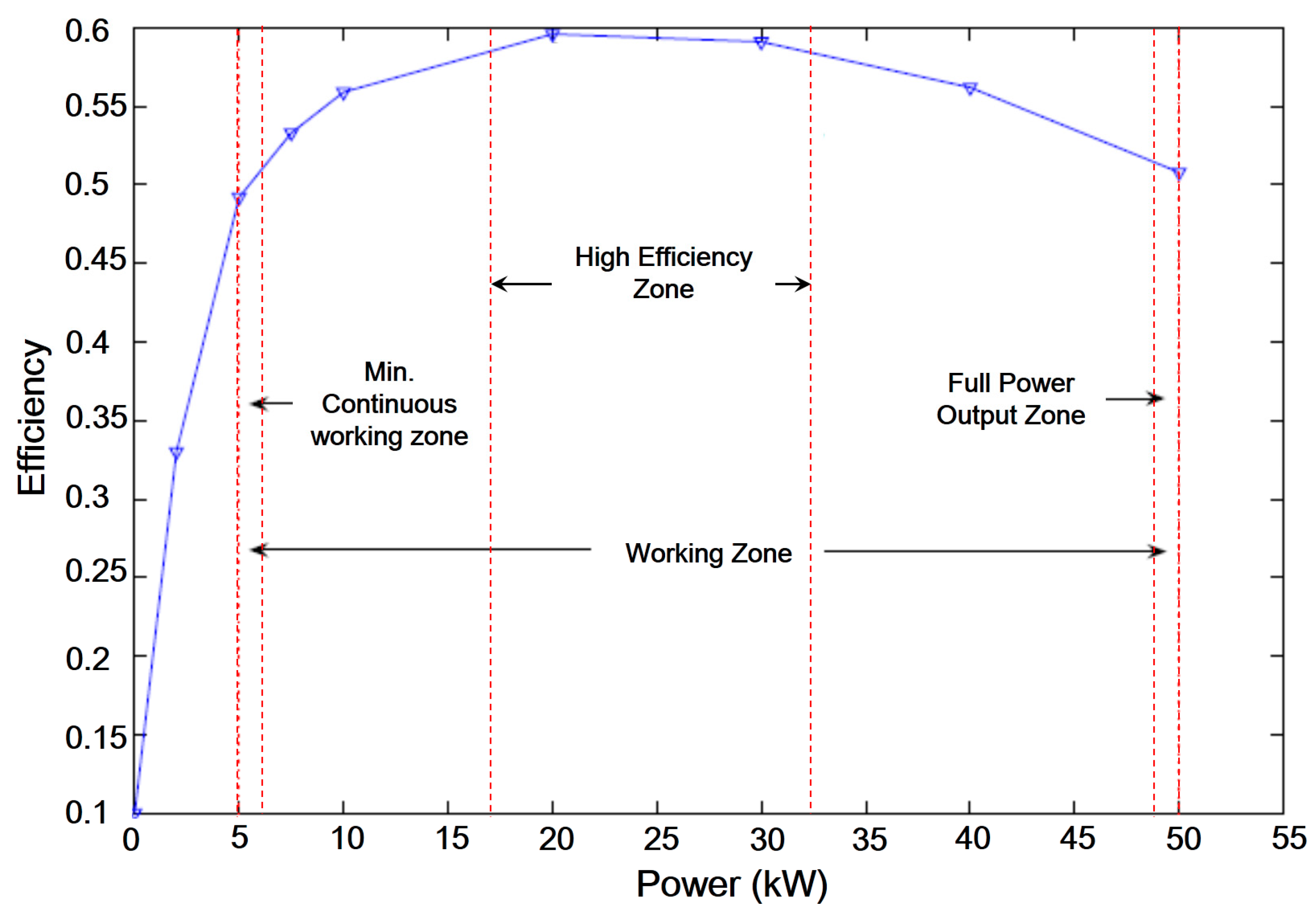
Each fuel cell engine has its working curve, with a minimum continuous working zone, high-efficiency zone, and full power output zone, as the example [
18] shows in
Figure 5.
Thus, the working boundary of FCE was checked as below:
- (1)
It is the goal to keep FCE running in its high efficiency zone of with battery pack. Outside the working region it is necessary for the battery pack alone to drive the motor, so the minimum energy capacity of battery pack needs to be calculated under all kinds of the possible drive conditions.
- (2)
The FCE needs specific time to start or to shut down itself, it is better to avoid the frequent start-stop operation for longer stack life span.
- (3)
The battery pack needs a minimum energy reserved to start FCE.
- (4)
The battery pack has its efficiency characteristics affected by the operation temperature, discharge rate, SOC (state of charge), etc.
With above boundary analysis,
and its ideal working zone can be calculated:
Here, is the max FCE efficiency.
3.5. Battery Sizing Determination
When the FCE sizing is determined, the battery pack sizing can be determined with Equation (7) by:
where
is the BP sizing energy capacity,
is the BP allowed frequent working energy capacity,
is the BP efficiency,
is the DC bus voltage, and
is the BP discharge rate.
With the minimum energy reserved for system startup and the regeneration of energy by motor breaking:
where
is the reserved energy for startup,
is the maximum reserved energy capacity for regeneration.
3.6. Dynamic Hybrid Degree and Vehicle Control Strategy
As discussed earlier, the dynamic hybrid degree is the essential about vehicle control, the traction motor output power can be obtained by voltage and current, which is driven by the target torque and speed. The FCE is a low-frequency energy resource, and is proposed to working in the high-efficiency zone most of the time so that the battery pack will be working in discharge or charge states to meet the rest of the power request.
With Equation (12), the battery pack SOC thresholds can be defined:
where
is the low threshold, and
is the high threshold. The dynamic hybrid degree is to control the
output based on the target traction motor torque between the
and
. One of vehicle control strategy’s targets is to keep the FCE running in the high-efficiency zone and with less start-stop behavior, so the static hybrid degree concept provides a control boundary for vehicle control algorithm design, and the dynamic hybrid degree is quite useful in evaluating and optimizing the effect of the control algorithm.
4. Application and Results Analysis
4.1. Testing Platform Design
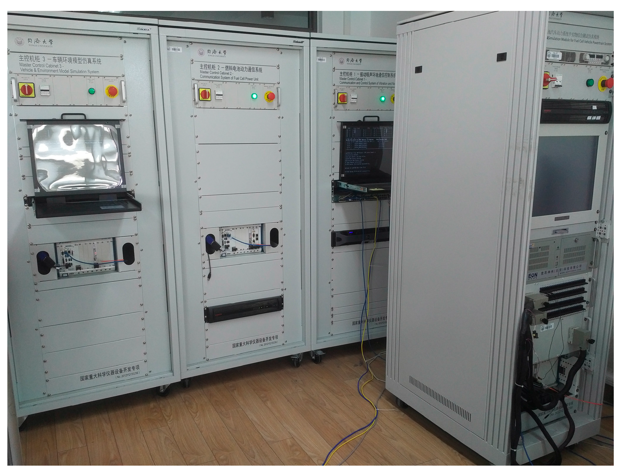
An integrated testing platform was designed at the Clean Energy Automobile Engineering Center of Tongji University. This platform can fully fulfill the hybrid degree testing process discussed in this paper in
Figure 6. During the MiL/SiL step, the environment model including the vehicle and testing model is running in the main controller, as well as the powertrain components model, the high voltage unit as a physics simulator with multiple channels, can simulate the traction motor, battery pack, and FCE separately under high-level voltage conditions. During the HiL testing step, testing affiliates will emulate the road dynamic resistance, air temperature, air humidity, air pressure, and even the vertical shaking of the vehicle. The main controller cabinet of the testing platform used a PXI real-time controller, as shown in
Figure 7 4.2. Subsystem Mode Design
In this application, the test will be applied on a SUV fuel cell vehicle with the specification shown in the
Table 2.
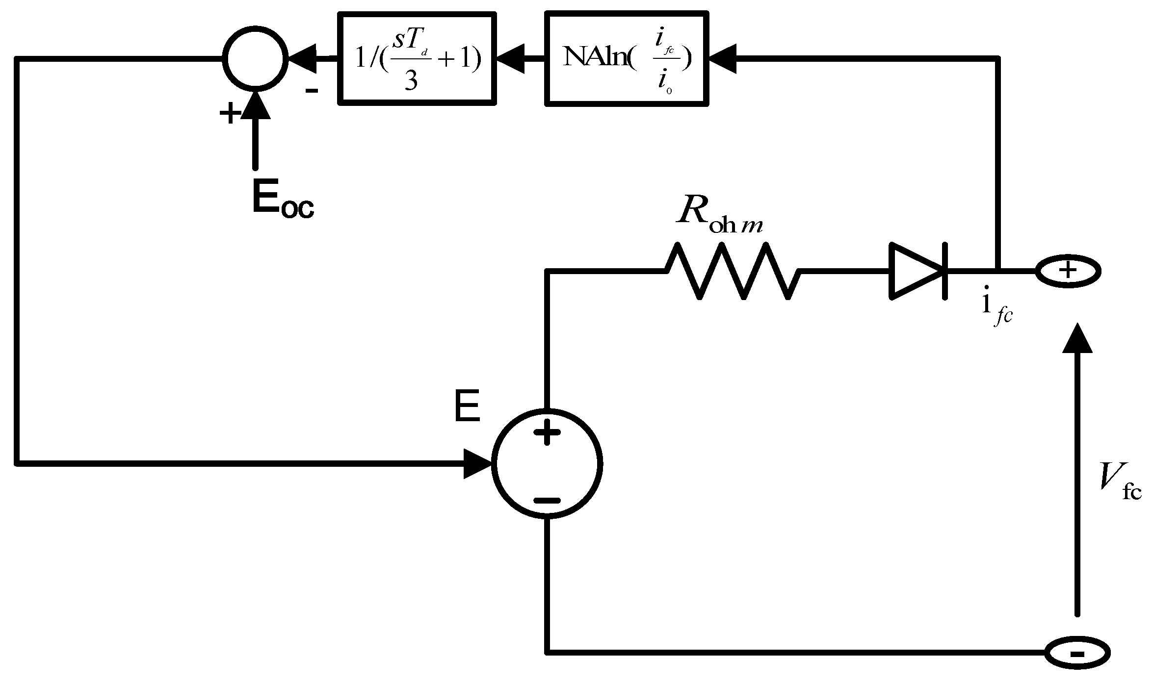
The FCE model was designed with the following equations [
19]:
: Open circuit voltage;
: Fuel cell number;
: Tafel slope;
: Exchange current;
: Fuel cell current;
: Response time;
: Internal resistance; and
: Fuel cell voltage.
The Tafel slope is the slope of the Tafel equation, as Equation (17), which is applied to describe the fuel cell over potential to overcome the activation energy of the electrochemical reaction on the surface of the catalyst.
Fuel cell engine principle model is shown in
Figure 8.
The battery pack model was designed with following equations [
20]:
: Battery output voltage;
: Open circle voltage;
: Output current;
: Internal resistance;
: Sate of charge;
: Temperature.
The traction motor model was designed with following equations:
: Target torque;
: Efficiency of the traction motor;
: Current of the traction motor; and
: DC Bus voltage.
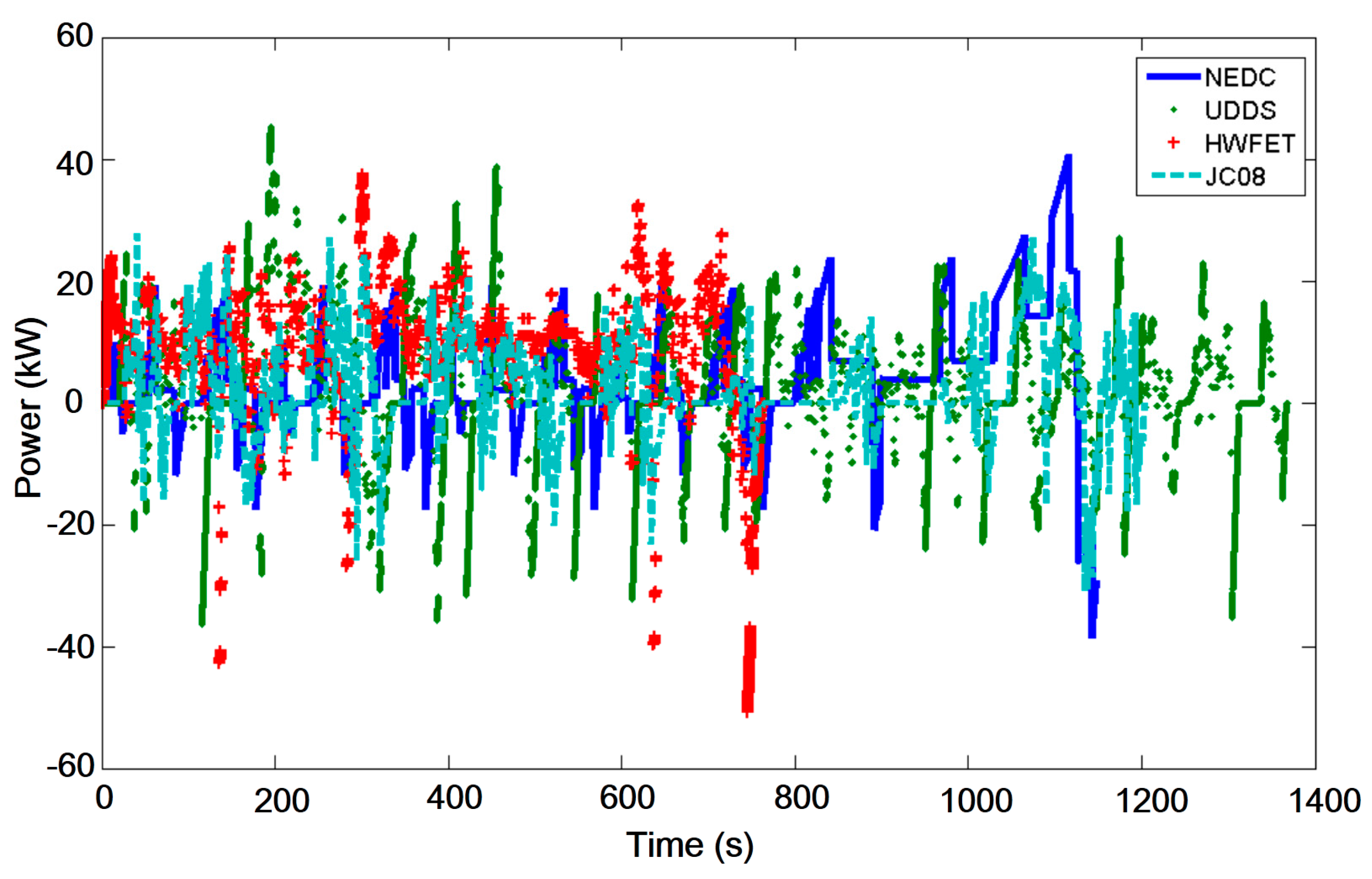
4.3. Testing Results and Analysis
The testing was implemented by MiL on the testing platform, NEDC (New European Driving Cycle), UDDS (Urban Dynamometer Driving Schedule), HWFET (Highway Fuel Economy Cycle), and JC08 (Japanese Chassis Dynamometer Test Cycle) driving cycles are applied. Fifty kilowatts is chosen for the traction motor rated power based on the testing results in
Figure 9 to cover all of the driving cycles.
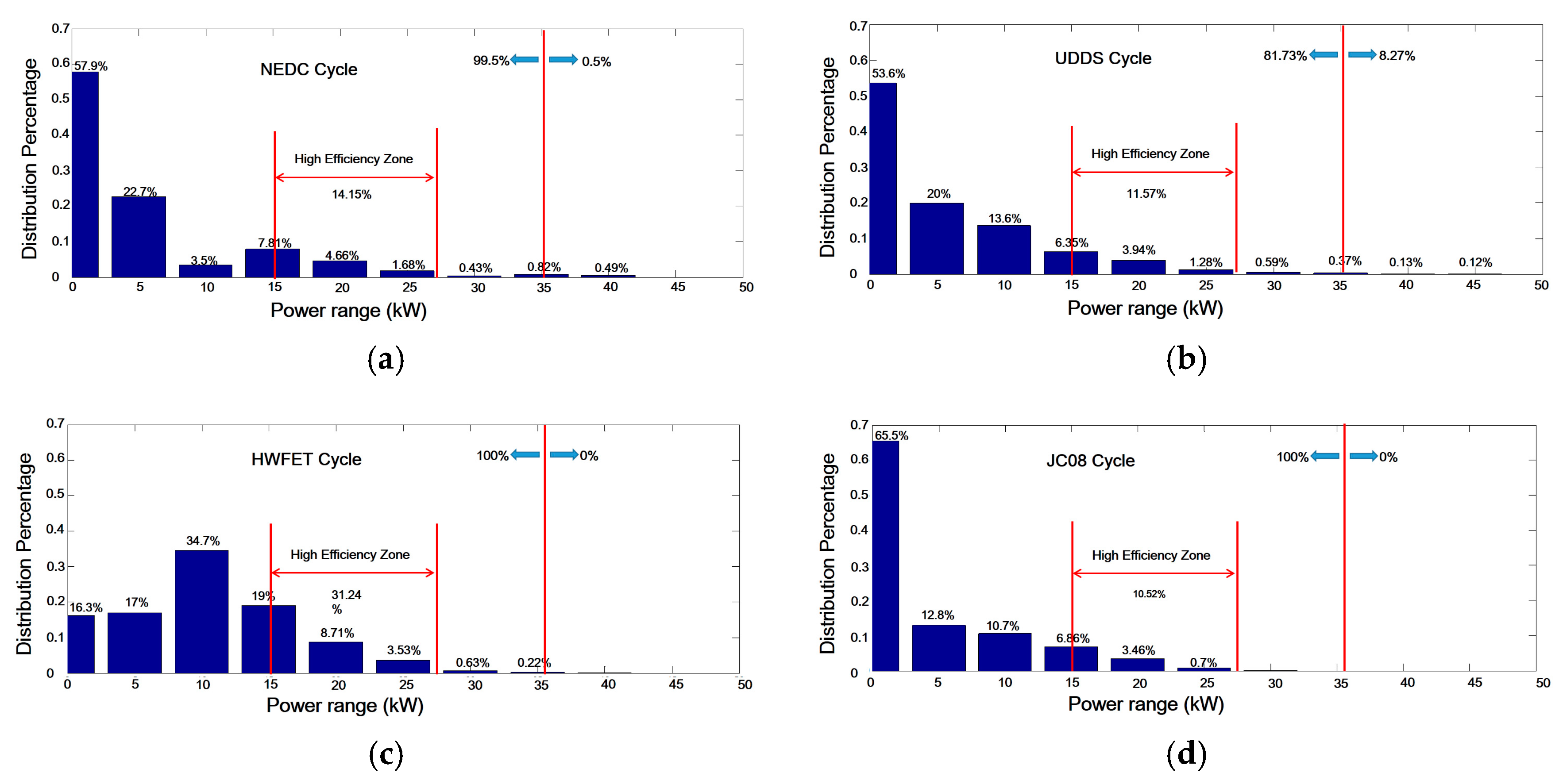
Power distributions in each cycle are obtained in
Figure 10, and 35 kW is chosen for
to cover more than 80% traction motor power request, which allows the FCE working in the high-efficiency zone directly to cover about 10–14% cycle condition. Vehicle control algorithm is supposed to avoid the low-efficiency working zone with SOC state control, which is the value of the dynamic hybrid degree concept in Loop 2.
The is 14.28 kW, TM efficiency is 0.9, vehicle accessory load is about 3–5 kW, so there is 18.87–20.87 kW power requested to meet continuously highest speed working condition, and which is also in the high-efficiency zone of the FCE.
Testing results are shown in the
Table 3, which can define the basic sizing parameters and guide the vehicle control algorithm design.
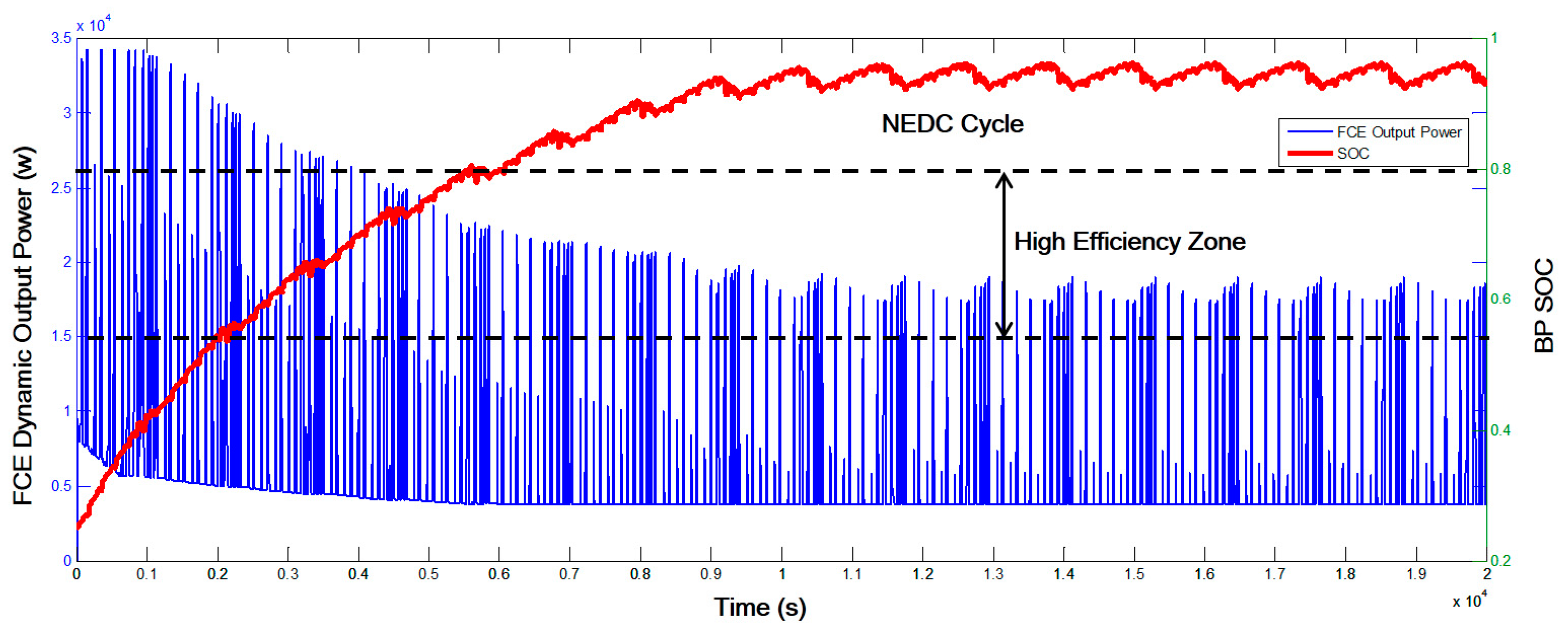
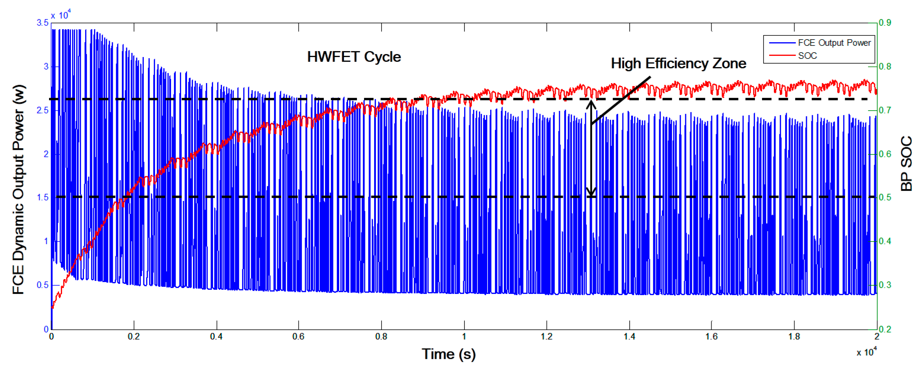
During dynamic hybrid degree testing, the FCE was taken as the main power resource with sliding output changes, and the battery worked with dramatic high frequency changes to meet the power gap requested by the traction motor. The vehicle control algorithm which is supposed to control directly and indirectly to meet road load changes was evaluated and optimized. and should be balanced all the time for high efficiency and maximum dynamic power output ().
In
Figure 11 and
Figure 12, the initial SOC = 0.2, the testing period is 20,000 seconds, and the NEDC cycle and HWFET cycle were used with the same vehicle control algorithm. At the beginning, the FCE worked with full power output to improve the battery SOC state over
, then FCE was supposed to work in the high efficiency zone under
. The battery pack has stored enough energy to meet the
request with low coverage of the FCE high-efficiency zone when maximum SOC is close to
in
Figure 11 under the NEDC cycle, and it has better coverage of the FCE high-efficiency zone when the stable SOC reaches approximately 0.7 in
Figure 12 under the HWFET cycle. However, the stable SOCs at end of the testing are different under NEDC and HWFET cycles with the same vehicle control algorithm. Different static hybrid degrees will cause different control effects with same vehicle control algorithm, and the same static hybrid degree and control algorithm will have different economy performances under different driving cycles. Thus, the powertrain system architecture and subsystem sizing should be designed and evaluated seamlessly with vehicle control algorithm design and optimization, hybrid degree concept provides very useful testing method for the whole powertrain system development process.
5. Conclusions
The XiL testing method, as a brand new solution, was applied in the FCV hybrid degree test. Meanwhile, the hybrid degree has been re-defined from the view of electric energy capacity, and it consists of the static hybrid degree for system architecture design and the dynamic hybrid degree for vehicle control strategy design. An integrated testing platform based on XiL technology has also been introduced with platform architecture design and subsystem model design. With designed two testing loops, the sizing of the FCE, battery pack, and traction motor with powertrain architecture was determined, the control strategy can be evaluated seamlessly, and a systematic powertrain testing solution can be achieved through the whole development process. The test results show the novelty and efficiency by the re-defined hybrid degree combined with the XiL testing method.
- (1)
Powertrain system sizing of an SUV fuel cell vehicle has been tested and verified, and the results show that the vehicle design parameters can be satisfied.
- (2)
The vehicle control strategy can be improved efficiently by the X-in-the-loop method and re-defined the hybrid degree.
As a future work, the authors would like to study the following issues: (1) keep improving the environment model and components model with testing data; (2) vehicle control strategy optimization, and (3) explore the vehicle in the loop testing by the XiL testing method.


