Winding Design and Analysis for a Disc-Type Permanent-Magnet Synchronous Motor with a PCB Stator

1
School of Electrical Engineering and Information, Tianjin University, No. 92 Weijin Road, Tianjin 300072, China
2
Substation Operation and Maintenance Room of State Grid Shenyang Electric Power Supply Company, No. 94 Eight Jing Street, Shenyang 110000, China
*
Author to whom correspondence should be addressed.
Energies 2018, 11(12), 3383; https://doi.org/10.3390/en11123383
Submission received: 5 October 2018
/
Revised: 27 November 2018
/
Accepted: 29 November 2018
/
Published: 3 December 2018
Abstract
:The stator structure of a disc-type permanent-magnet synchronous motor is a printed circuit board (PCB). The design of stator windings has a direct influence on motor performance and the utilization rate of the stator. However, in some respects, PCB processing technology limits the development of the disc-type electric motor with a PCB stator. For example, the wiring of the stator winding and the connections of the ends are single. In this paper, an improved winding was designed to improve the output power. The analytic expressions for the back electromotive force (EMF) and other parameters such as power, winding resistance, and eddy loss are established, respectively. According to finite-element theory, the characteristics of the improved winding and distributed winding under no load and load were simulated and analyzed. It is concluded that the improved winding not only improves no-load back EMF, along with output power and efficiency under load, but also the utilization rate of the stator was greatly improved. Finally, a prototype was made to verify the design that has a certain reference value for the design of a disc-type permanent-magnet motor with a PCB stator.
1. Introduction
A disc-type motor with a printed circuit board (PCB) stator is different from a traditional radial motor. The stator and rotor of the disc-type motor with a PCB stator are usually arranged along the axial direction, and, structure-wise, it has a single rotor, single stator, middle stator, and multiple discs. Because of problems that need to be resolved in traditional radial motors, such as torque ripple, heat dissipation, and the low utilization rate of the rotor core, disc-type motors have received increasing amounts of attention since the 1940s [1]. At present, disc-type motors are widely used in flywheel energy-storage systems, the equipment of mechanical and electronic integration, and in other fields [2,3]. Of course, PCB stator disc-type motors have numerous advantages, like light weight, high power density, and small torque ripple [4,5,6,7].
The key factor in the design of a PCB stator disc-type motor is the PCB winding. The authors in [8] designed and optimized rhombus PCB windings, reducing machine volume, but the rhombic winding still occupied a large area and had a short effective conductor part. Reference [9] applied the spiral PCB winding to microsatellite generators, which solved the problem of having a small space for installation. The authors in [10] designed a wedge-shaped PCB winding with fewer losses and higher efficiency, which provided a solution for low-speed marine-current applications. Reference [11] shows that waveform PCB windings have higher efficiency and lower losses than spiral PCB windings. A new PCB winding designed in [12] combined the advantages of trapezoidal and circular windings, and, increasing back EMF and power, has a shorter end and higher efficiency than trapezoidal, circular, and rhombus windings. The inclination angle and radial length of the PCB winding in [12] were optimized with the objective of maximizing the ratio of torque to copper consumption [13]. In [14], the width and turns of the spiral winding were optimized, which increased the coil space factor and output power of the motor. In [15], nonoverlapping waveform windings without end effects were used in high-speed axial flux motors without an iron core, which enhanced the torque output. Reference [16] designed a two-phase waveform PCB winding with an integer slot, which reduced the harmonic components and increased the torque density of the motor.
In summary, it can be seen that research on stator windings is mainly concerned with the shape and optimization of non-overlapping concentrated winding (such as rhombus, waveform, trapezoidal, and circular windings) at home and abroad. Distributed windings and their connection mode at the ends of windings, and the utilization ratio of stator winding, have not been much studied.
The improved winding designed in this paper improves the utilization of the stator when the stator outer diameter is constant. The output power, loss, and efficiency of this motor were compared and analyzed between existing distributed windings and improved windings under various load conditions.
The results show that the improved winding has more advantages than the distributed winding, and it improves heat-dissipation capability and efficiency, and reduces the copper consumption. It is also very beneficial to the enhancement of power density. Finally, the correctness of the analysis was verified by the prototype experiment.
2. Disc-Type Permanent-Magnet Synchronous Motor with PCB Stator
2.1. Structural Characteristics
The motor mentioned in this paper has the structure of dual rotors and a single stator. The structure of the prototype is shown in Figure 1.
The stator winding was used in the form of a printed circuit board, which can effectively reduce the axial size of the motor. The stator is coreless and slotless, and has no teeth. The concept of the pole-slot match is rarely seen as a direct-viewing manifestation. Some theories of conventional radial motors cannot be directly applied. In this paper, a conductor was taken as a slot, as shown in Figure 2, a coil was a single turn, the upper and lower parts of the coil are located in two “slots”, and the windings are usually single-layer windings.
At present, the main types of stator windings are the spiral winding and distributed winding. In this paper, a new improved winding was designed. The structure of the three types of windings is shown in Figure 3. The spiral winding, as shown in Figure 3a, is made up of a concentric circle of each coil. Each phase is connected in a series by a number of coils. The coil inside the inner circle has shorter length in its effective part, and has a smaller winding pitch coefficient. The impedance voltage drop in this area is likely to be larger than the back EMF, which not only has little effect on increasing power density, but it also increases winding resistance. This winding also has larger copper consumption and lower efficiency.
As shown in Figure 3b, the distributed winding, different from the spiral winding, has the same effective conductor length. The effective conductor, at the same position in each layer, is connected in parallel through the hole to increase the current and reduce the resistance of the winding. The distributed winding, compared with the spiral winding, can make full use of the space under the permanent magnet, and has better output performance under the same air gap flux density. It also has a higher winding coefficient, and lower copper consumption of the winding.
The effective conductor is expanded based on current density. The fewer the layers are, the wider the conductor is at the same current density. For the prototype mentioned in our manuscript, the PCB stator has 12 layers. The number of effective conductor PCB stator layers is 12, while the outer-end and inner-end layers are two and four, respectively, which means that the outer ends are six times wider than the effective conductor, and the inner ends are three times the width of the effective conductor. The inner and the outer ends occupy a large area, which lowers the effective utilization of the stator and output power. Moreover, the ends make the area in the inner diameter very “crowded”, hence making wiring difficult. The more ends there are, the lower the efficiency and the greater the consumption of copper are.
The improved winding designed in this paper solves those problems. Its structure is shown in Figure 3c. Compared to distributed windings, the length of the ends and the space occupied by them can be greatly reduced in the improved winding. This makes the wiring convenient and increases the input current.
The effective conductor of the improved winding is bigger than that of the distributed winding, while the stator outer radius of the improved winding is the same as the distributed winding. The physical dimensions of the improved-winding and the distributed-winding types are shown in Table 1.
From Table 1, it can be seen that the stator outer radius of both PCB windings are the same while the stator inner radius has been increased from 13.8 mm to 17.2 mm for the improved winding and effective conductor outer radius also increased from 38.7 mm to 43.5 mm for the improved winding while the effective conductor inner radius of the improved winding remain the same.
2.2. Motor Parameters
The prototype mentioned in this paper has four pairs of poles, 120 slots, a rated speed of 7500, rpm and a rated current of 10.4 A. The inner diameter of the rotor is 44.8 mm, and the outer diameter is 77.4 mm. Considering the influence of the eddy current, the width of the effective conductor is 0.64 mm. The basic parameters of the prototype with the improved winding are shown in Table 2.
2.3. Finite-Element Modeling of PCB Stator Disc-Type Motor
When the PCB stator disc-type motor is simulated under steady operating conditions, the motor model and the magnetic field are periodically repeated along the circumferential position of the motor. The structure and magnetic field of each pair of poles are the same. The model of a pair of poles is taken as the solution domain to resolve, namely, the one-fourth model. The motor solution-domain model and the winding solution-domain model are shown in Figure 4 and Figure 5. The following assumptions are made to the solution-domain model:
- (1)
- The permeability of the coil is similar to that of air, and it is regarded as part of the air gap.
- (2)
- The motor field is entirely inside the air domain, and the magnetic field in the outside air domain is zero.
3. Analytical Design
3.1. Analysis of the Winding Coefficient
The winding coefficient means that the back EMF should be discounted when short pitch coils and distributed windings are used. For the improved winding in this paper, it can be regarded as single-layer winding. The short pitch coefficient is usually equal to 1 and its winding coefficient is equal to the distribution coefficient. So, the formula of the winding coefficient is as follows [17]:
where kwv is the v-order harmonic winding coefficient, and kqv is the v-order harmonic distribution coefficient. q is slots per pole per phase, α1 is the electrical angle between the two effective conductors, and v is harmonic order.
3.2. Power Analysis
The area of the magnetic field for each pole of the PCB stator disc-type motor is given below [18]:
where Di and Do are the inner and outer diameter of magnet, separately. Di is also the effective conductor’s inner diameter, while Do also is the effective conductor’s outer diameter. γ = Di/Do is the ratio of the inner and outer diameters.
The fundamental magnetic flux per polar is:
where Bav is the fundamental average magnetic density of the air gap, and αi is the effective pole-arc coefficient. Bδmax = αiBav is the maximal air-gap magnetic flux density of the fundamental wave. The corresponding phase back EMF E0 under no load is:
where f is the fundamental frequency, N is the number of turns in the series/phase, and kw1 is a fundamental winding coefficient.
The phase current based on the electrical load at the inner diameter of the motor is determined as follows:
where t is the layers of the PCB board, A is the maximal electrical load at the inner diameter, and a is the parallel branches. Generally, the value of a is equal to 1.
In this paper, the PCB stator disc-type motor can be regarded as an unsaturated, non-salient pole machine, so its electromagnetic power can be expressed as follows:
where Ψ is the inner power factor angle.
3.3. Analysis of Copper Loss
Copper loss occurs when the current flows through the winding and lowers efficiency. The calculation formula for phase resistance is as follows:
where ρ is the resistivity of the copper wires, N is the number of turns in the series/phase, ln is the length of the nth coil, and Sn is the sectional area of the nth coil.
Copper loss can be expressed as follows:
3.4. Eddy Loss
Because of the PCB stator disc-type motor without the iron core, winding cannot be placed in the stator slot like the motor with an iron core. Its winding is directly exposed to the magnetic field in the air gap. With the rotation of the motor, there would be eddy loss in the winding; this problem would be especially more prominent in high-speed motors. Eddy current loss is related to conductor width, frequency of the source, and the amplitude of the magnetic flux density in the air gap. The expression of eddy loss is as follows [19,20]:
where ρ is the resistivity of the copper wires, wL and b are the width and length of effective conductor, respectively, Bmtλ and Bmaλ are the ν-order harmonic amplitude of tangential and axial flux density, and ηd is the distortion coefficient of the flux-density waveform. It can be seen from the formula that the eddy loss is proportional to the square of frequency and the cube of effective conductor width. Therefore, for the PCB stator disc-type motor, the effective conductor width should be taken into full consideration to lower eddy loss, especially for high-speed motors.
3.5. Efficiency
The equations for the efficiency calculation are the following:
where P2 is output power, T2 and n2 are output torque and speed, and ΔPmec is the mechanical loss, which includes air-friction and bearing-friction loss. Because the size and power of the prototype are small, the mechanical loss is estimated to 1.5 percent of the rated power [1]. ΔPad is stray loss, the reason for which is very complicated, so it’s hard to determine its value. In this paper, it is estimated to be 0.5 percent of the motor’s rated power [17]. The unit of all losses is Watts.
4. Simulation and Analysis of the Results
4.1. Simulation Analysis of No-Load Characteristics
Under the conditions of the same outer diameter, the amplitude of the air-gap fundamental flux density for the improved winding and the distributed winding are 0.82 and 0.84 T, respectively, at average radius. The amplitude of air-gap flux density of the improved winding decreased by 2.3%. This is because the area of the magnet became larger under the condition of the same thickness of the magnet and the back iron, the saturation appears in the back iron. Accordingly, the air-gap fundamental flux density of the improved winding was reduced. The air-gap flux density of the improved winding is shown in Figure 6, and the magnetic flux distribution of the motor is shown in Figure 7.
The improved winding makes the stator more fully utilized and the structure more compact. The effective conductor length is longer at the same stator size, so the no-load line back EMF is higher. The waveform and harmonic decomposition of the no-load line back EMF of the two kinds of windings are shown in Figure 8 and Figure 9. It can be seen that the amplitudes of the no-load fundamental line back EMF of the improved winding increased to 29.16 from 21.43 V, increasing by 36%. The total harmonic distortion of the two kinds of windings is 2.3% and 2.1%. Therefore, the improved winding is clearly superior in improving the no-load back EMF compared with the distributed winding.
4.2. Simulation Analysis of Load Characteristics
This section compares the load characteristics of an improved winding and distributed winding by changing the current. This paper presents 20 kinds of working conditions in which the current changes from a 0.1 times-rated current to a twice-rated current and a 0 times-rated current stand for a no-load condition. The current and loss curve is given in Figure 10.
The no-load loss of the PCB stator disc-type motor was mainly due to eddy loss. It can be seen from Figure 10 that the eddy loss of the improved winding was larger than that of the distributed winding, because the effective conductor of the improved winding is longer. However, because winding resistance is mainly composed of the end resistance, and the improved winding increases the effective conductor while reducing the ends of the winding, the improved winding has lower copper loss. The resistance of the distributed and improved windings was 0.0741 and 0.0604 ohms, respectively; resistance was reduced by 13.6%. It can be seen from Figure 10 that, as the current increased, the loss of the two types of winding increased as well. In addition, the loss of the distributed winding increased faster, and the loss of the two windings was near 1.2 times of that of the rated current. When the current was greater than 1.2 times of the rated current, the loss of the improved winding was lower than that of the distributed winding. This is because the larger the current is, the greater the copper loss that would account for the total loss.
Furthermore, the output power of the distributed winding and improved winding was 283 and 398 W, respectively, at rated points, increasing by 40%. The curve for the output power and current is shown in Figure 11 at the rated speed. From Figure 11, for a longer length of the effective conductor, the output power of the improved winding was higher than that of the distributed winding.
The improved winding not only increased power but also improved efficiency. The efficiency curve is shown in Figure 12 at the rated speed. The efficiency of the distributed winding and improved winding was 89.37% and 91.46% at the rated point, increasing by 2.09%. The maximum efficiency of the improved winding was 91.83%, at 0.9 times of the rated current point. The maximum efficiency of the distributed winding was 90.02%, at 0.7 times the rated current point. The distributed winding had more copper loss, so the point at which variable loss was equal to the invariable loss appeared in advance. So, the maximum efficiency point appeared in advance. The output torque of the two kinds of windings at the rated point is shown in Figure 13. The average torque of the distributed winding and improved winding was 0.36 and 0.51 N·m, respectively, at the rated point, increasing by 41%.
For the PCB stator disc-type motor, the proportion of the effective conductor in the stator space, namely, the effective utilization rate of the stator winding, directly affects the torque output, efficiency, and power of the motor. However, the line width of the effective conductor and the wiring methods are inevitably limited by the space and processing technology of the PCB, which means that the ends had to occupy a certain space in the stator, especially in the case of a high current. Those affect the utilization rate of the stator winding and the further enhancement of power. The utilization rate of the stator of the two kinds of windings is shown in Figure 14. The utilization rate of the distributed winding stator was 46.89% and that of the improved winding stator is 68.89%, increasing by 22%. The area of the stator winding was reduced by 4.02%, and the area occupied by the effective conductor climbed 39.6%. Therefore, the power, torque, and efficiency of the motor could be greatly improved by improving the motor windings.
5. Experimental Results
In order to verify the performance of the improved winding designed in this paper, a prototype was made based on the above analysis. The prototype test was carried out on the experimental platform. Figure 15 shows the stator and prototype with the improved winding, and the experimental platform can be seen in Figure 16.
The experiment of measuring winding resistance with a QJ44 type double-arm bridge is shown in Figure 17. Measurement results of the phase resistance of the distributed winding and improved winding are 0.078 and 0.0635 ohm, respectively. The experimental values of these two kinds of windings’ phase resistance differ from their simulation values by 4.88% and 5%. Measurement results of the no-load line back EMF of the prototype are shown in Figure 18.
It can be seen that the line back EMF amplitudes of the improved and the distributed winding are 28.5 and 21 V, respectively, which are in good agreement with the fundamental wave amplitudes simulated in Figure 9. Some parameters, such as line width, effective conductor length, copper thickness, and the size of the through-hole, are affected by the manufacturing technology of the PCB, as long as some small errors are brought about by the measuring instrument.
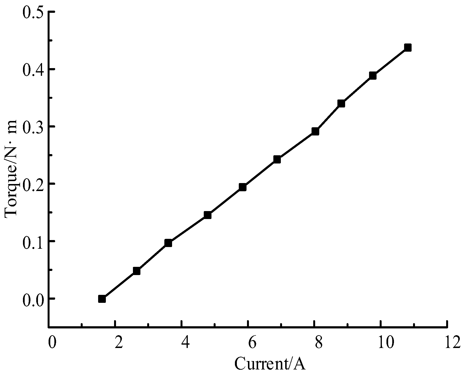
In addition, based on the existing experimental conditions and equipment, the load test of the improved winding was conducted at the working condition of 3000 rpm, and the curve of the torque at this speed is given in Figure 19. The figure shows that the no-load current was 1.5 A because there exists a certain electromagnetic torque to overcome the load torque. When the current was 11.1 A, the experimental results of the output torque were 0.45 N·m and the simulation results of the torque were 0.53 N·m, reducing by 15.1%. Under the current conditions of the existing equipment and platform, this error is within a controllable range.
It can be seen that the deviation between the experimental value and the simulation result is in an allowable range of engineering. So, we can draw the conclusion that the three-dimensional finite-element calculation model established in this paper is reasonable.
6. Conclusions
In this paper, the different stator winding types of a PCB stator disc-type motor were studied, and the characteristics of the distributed winding and the improved winding were compared and analyzed. The conclusions are as follows:
- (1)
- Simulation values were in good agreement with the test data, which showed that the three-dimensional finite-element calculation model established in this paper is reasonable.
- (2)
- For the same stator diameter, the improved winding increased the space utilization of the stator, and the space utilization of the stator reached 68.89%, which is 22% higher than that of the distributed winding. It is more compact in structure and particularly suitable for the requirements of limited motor-size situations.
- (3)
- By contrast, the amplitude of the no-load fundamental line back EMF of the improved winding increased by 36%, and output power increased by 40%. Its effective conductor size was longer. This does not only improve the output power and torque of the motor, but also its efficiency. It even reduces the loss by more than 1.2 times of the rated current.
From what has been mentioned above, we can draw the conclusion that the improved winding has great advantages.
Author Contributions
Conceptualization, X.W.; data curation, X.L.; formal analysis, H.L.; methodology, X.W.; project administration, X.W.; software, H.L.; supervision, X.L.; writing—original draft, X.W., H.L., and X.L.; writing—review and editing, X.W. and H.L.
Funding
The research described in this paper is supported by the National Natural Science Foundation of China (51577125).
Conflicts of Interest
The authors declare no conflict of interest.
References
- Tang, R.Y. Modern Permanent Magnet Machines Theory and Machines; China Machine Press: Beijing, China, 1997; pp. 310–311. [Google Scholar]
- Liu, Y. Analysis and Calculation of Disc Coreless PMSM Based on HALBACH Array; Tianjin University: Tianjin, China, 2005. [Google Scholar]
- Shao, L.; Fan, Y. Synchronous motor modeling and simulation of permanent magnet disk. Electr. Mach. Control 2006, 10, 61–69. [Google Scholar]
- Bianchi, N.; Bolognani, S. Design considerations for fractional-slot winding configurations of synchronous machines. IEEE Trans. Ind. Appl. 2006, 42, 997–1006. [Google Scholar] [CrossRef]
- Huang, Y.K.; Zhou, T.; Dong, J.N. An overview on developments and researches of axial flux permanent magnet machines. PCSEE 2015, 35, 192–205. [Google Scholar]
- Liu, B.; Liu, H. Analysis and testing and improved design for enhancing the electromagnetic torque ofdisc-type micromotor. PCSEE 2015, 35, 6519–6526. [Google Scholar]
- Dehez, B.; Markovic, M.; Perriard, Y. Analysis and comparison of classical and flex-PCB slotless wind-ings in BLDC motors. In Proceedings of the International IEEE Conference on Electrical Machines and Systems, Sapporo, Japan, 21–24 October 2012. [Google Scholar]
- Tsai, M.C.; Hsu, L.Y. Design of a miniature axial-flux spindle motor with rhomboidal PCB winding. IEEE Trans. Magn. 2006, 42, 3488–3490. [Google Scholar] [CrossRef]
- Wu, J.F. Design of a miniature axial flux flywheel motor with PCB winding for nanosatellites. In Proceedings of the International Conference on Optoelectronics and Microelectronics, Changchun, China, 23–25 August 2012. [Google Scholar]
- Moury, S.; Iqbal, M.T. A permanent magnet generator with PCB stator for low speed marine current applications. In Proceedings of the Developments in Renewable Energy Technology, Changchun, China, 23–25 August 2010. [Google Scholar]
- Wang, H.; Wu, J.F.; Li, Y. PCB stator winding in axial flux permanent magnet motor for reaction flywheel system. Opt. Precis. Eng. 2015, 23, 1004–1010. [Google Scholar] [CrossRef]
- Wang, X.Y.; Tian, Z. Shape design of windings of disc-type electric machine with PCB stator. Small Spec. Electr. Mach. 2016, 44, 29–33. [Google Scholar]
- Wang, X.; Li, C.; Lou, F. Geometry optimize of printed circuit board stator winding in coreless axial field permanent magnet motor. In Proceedings of the Vehicle Power and Propulsion Conference, Hangzhou, China, 17–20 October 2016; pp. 1–6. [Google Scholar]
- Wang, X.; Li, C.; Lou, F. Optimization design of PCB winding for axial flux permanent magnet synchronous motor. PCSEE 2017, 37, 6092–6100. [Google Scholar]
- Neethu, S.; Nikam, S.P. High speed coreless axial flux permanent magnet motor with printed circuit board winding. In Proceedings of the Industry Applications Society Meeting, Cincinnati, OH, USA, 1–5 October 2017. [Google Scholar]
- Marignetti, F.; Volpe, G.; Cecati, C. Electromagnetic design and modeling of a two phase axial flux printed circuit board motor. IEEE Trans. Ind. Electron. 2018, 99, 299–305. [Google Scholar] [CrossRef]
- Gu, C.L.; Chen, Q.F.; Xiong, Y.Q. Electric Machinery, 3rd ed.; Hua Zhong University of Science and Technology Press: Wuhan, China, 2010. [Google Scholar]
- Li, Z. Design of Permanent Magnet Motor; Xidian University Press: Xi’an, China, 2016. [Google Scholar]
- Wang, X.L. A winding eddy current loss suppression method for power-type axial flux permanent magnet machine with coreless-stator. Torp Technol. 2012, 20, 295–300. [Google Scholar]
- Wang, X.W.; Yang, G.J.; Wang, Y.T. Study of PCB winding loss in reaction flywheel motor with axial flux. Small Spec. Electr. Mach. 2016, 44, 5–9. [Google Scholar]
Figure 1.
Structure diagram of prototype of a printed circuit board (PCB) stator disc-type motor. (1) ends cap; (2) bearing; (3) back iron; (4) permanent magnet (PM); (5) hexagonal nuts; (6) cross sunk head screw; (7) PCB board.
Figure 1.
Structure diagram of prototype of a printed circuit board (PCB) stator disc-type motor. (1) ends cap; (2) bearing; (3) back iron; (4) permanent magnet (PM); (5) hexagonal nuts; (6) cross sunk head screw; (7) PCB board.
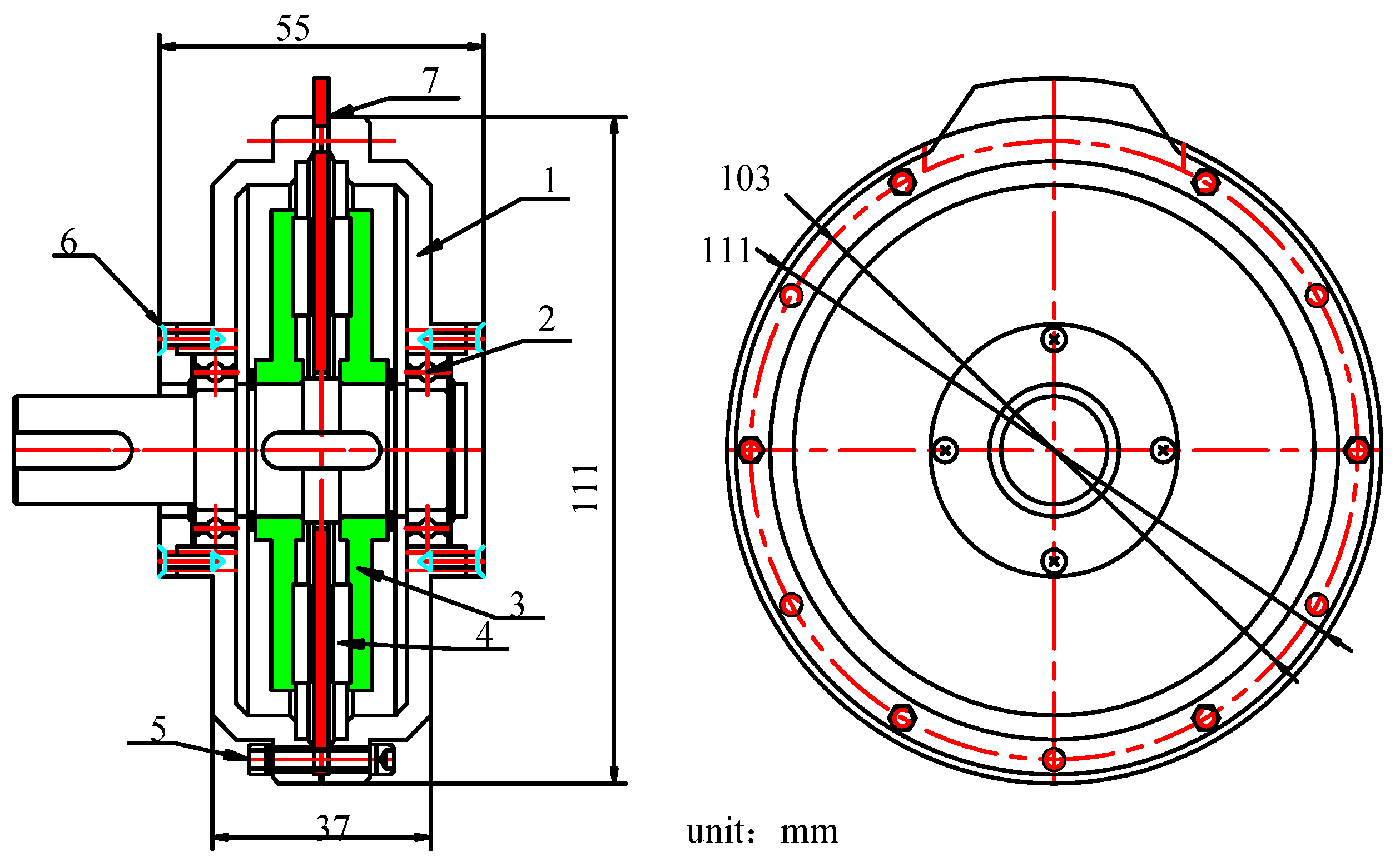
Figure 2.
Structure diagram of an equivalent stator “slot”.

Figure 3.
Schematic diagram of three different stator windings of one phase: (a) spiral winding; (b) distributed winding; (c) improved winding.
Figure 3.
Schematic diagram of three different stator windings of one phase: (a) spiral winding; (b) distributed winding; (c) improved winding.

Figure 4.
Solving domain model of the prototype.

Figure 5.
Solving domain model of stator of the prototype.

Figure 6.
Air-gap flux density waveform in an average radius.

Figure 7.
Flux density distribution of the motor.
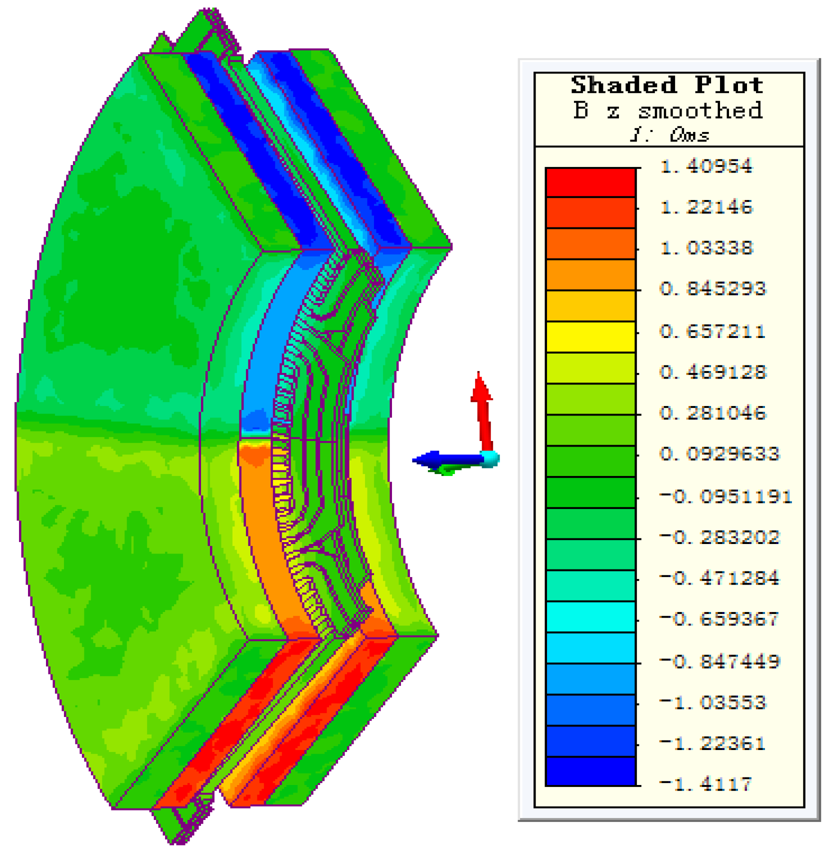
Figure 8.
No-load line EMF waveform.
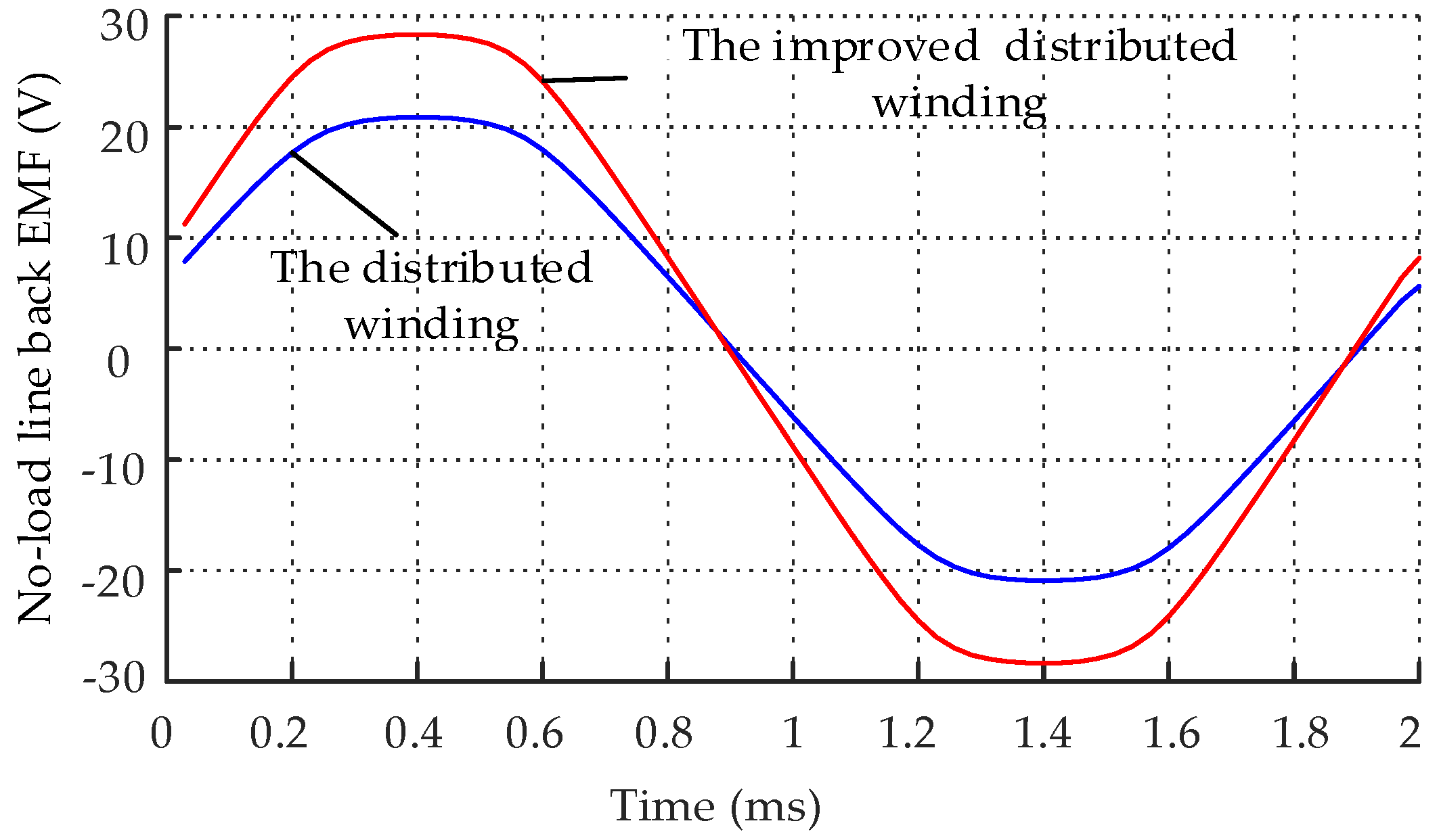
Figure 9.
Harmonic decomposition of the no-load line EMF.
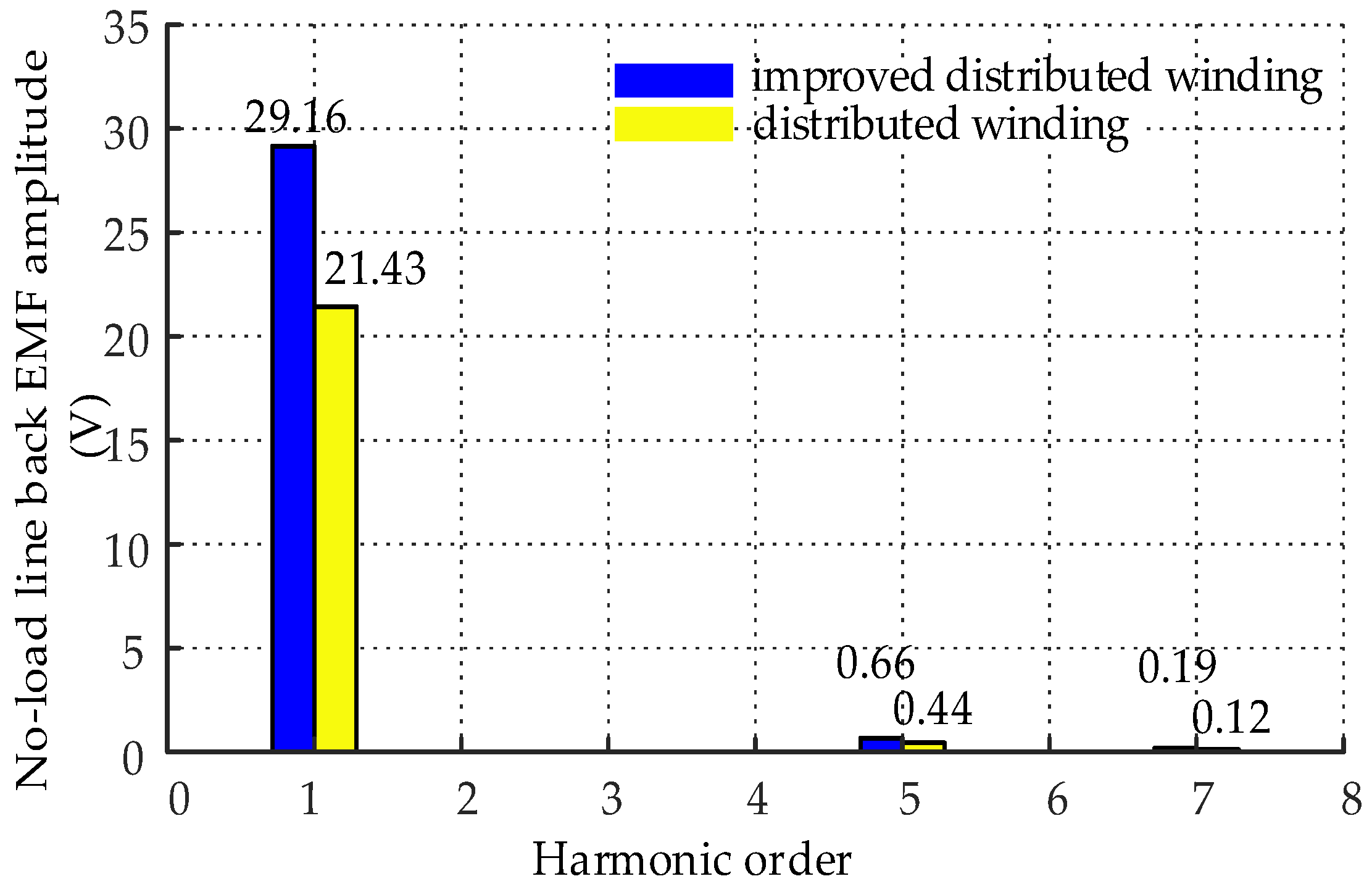
Figure 10.
Curve of loss with current.
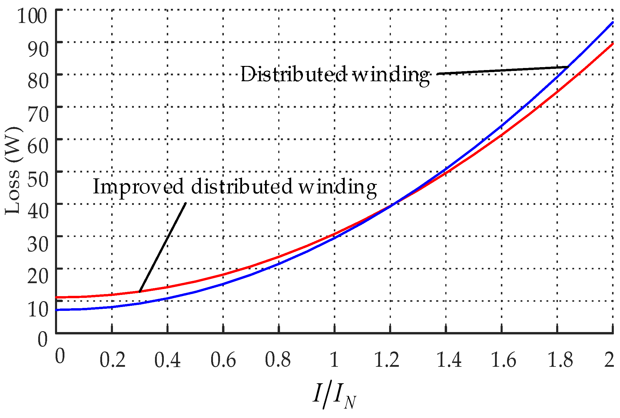
Figure 11.
Curve of output power with current.

Figure 12.
Efficiency curve of with current.
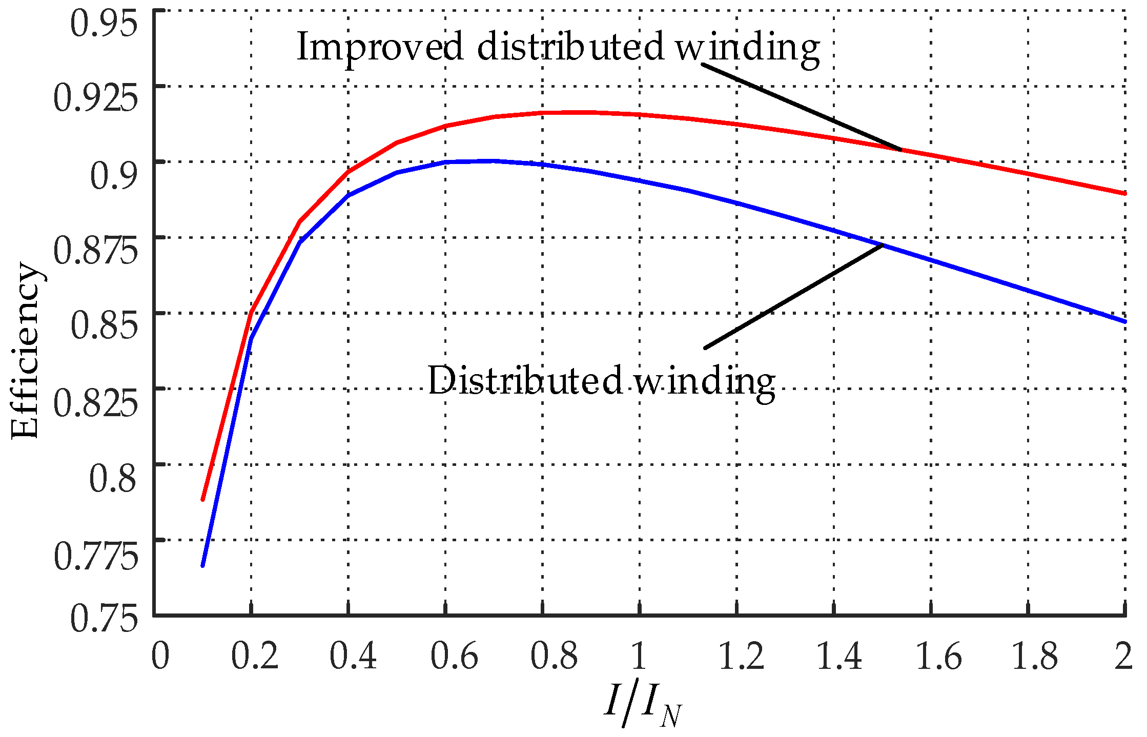
Figure 13.
Torque curve with time.
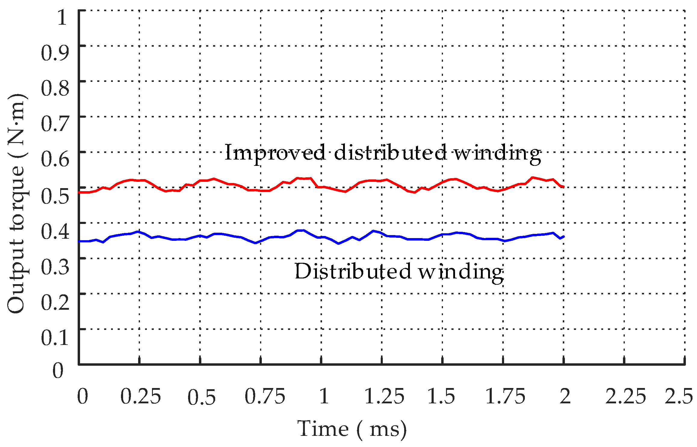
Figure 14.
Comparison of both winding utilization ratios.
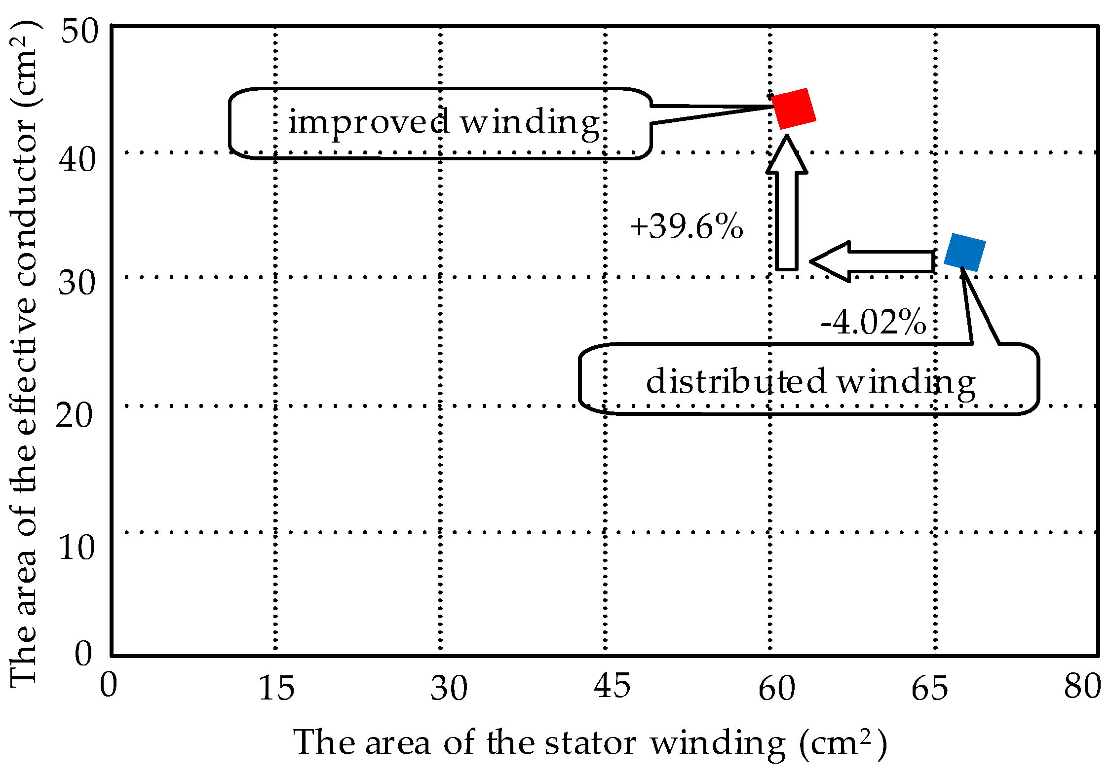
Figure 15.
Improved PCB stator and prototype.

Figure 16.
Experimental test platform.

Figure 17.
Resistance measurement; (a) resistance measurement of the distributed winding; (b) resistance measurement of the improved winding.
Figure 17.
Resistance measurement; (a) resistance measurement of the distributed winding; (b) resistance measurement of the improved winding.
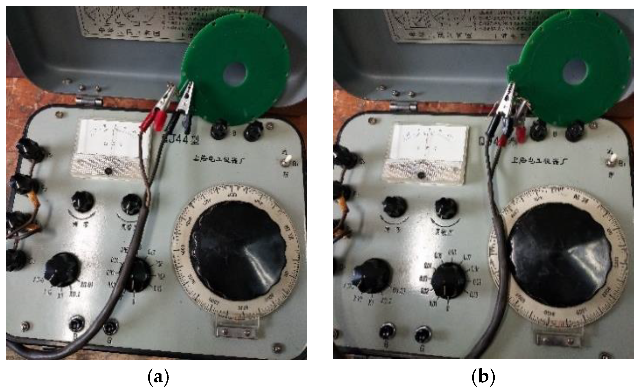
Figure 18.
Measured no-load line EMF curves: (a) measured no-load line EMF curves of improved winding; (b) measured no-load line EMF curves of distributed winding.
Figure 18.
Measured no-load line EMF curves: (a) measured no-load line EMF curves of improved winding; (b) measured no-load line EMF curves of distributed winding.
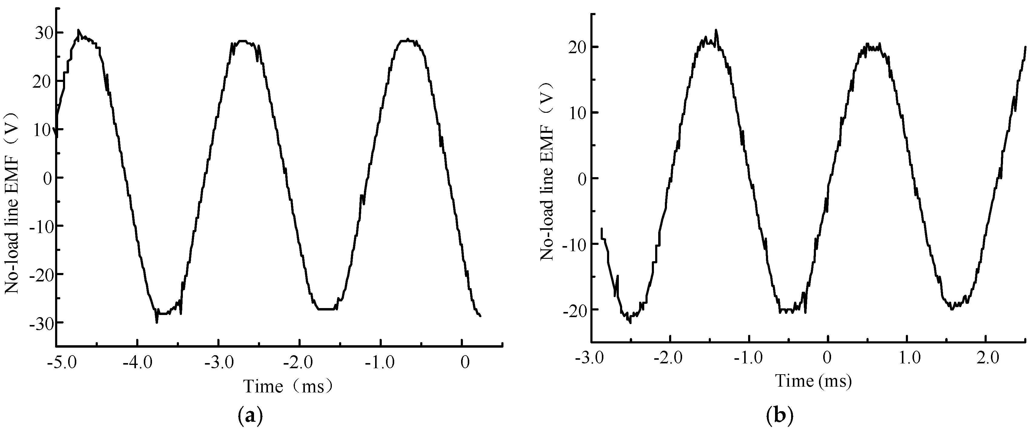
Figure 19.
Measured torque and current curves of the improved winding at 3000 rpm.

Table 1.
Physical dimensions of both PCB windings. R1, stator inner radius; R2, effective conductor inner radius; R3, effective conductor outer radius; R4, stator outer radius.
Table 1.
Physical dimensions of both PCB windings. R1, stator inner radius; R2, effective conductor inner radius; R3, effective conductor outer radius; R4, stator outer radius.
| Parameters | R4 | R1 | R3 | R2 |
|---|---|---|---|---|
| Distributed winding | 48.1 mm | 13.8 mm | 38.7 mm | 22.4 mm |
| Improved winding | 48.1 mm | 17.2 mm | 43.5 mm | 22.4 mm |
Table 2.
Basic parameters of the prototype with improved winding.
| Parameters | Designed Value |
|---|---|
| Rotation | 7500 RPM |
| Current | 10.4 A |
| Torque | 0.35 N·m |
| Power | 280 W |
| Number of winding turns | 20 |
| Number of poles | 8 |
| Thickness of conductor | 1.26 mm |
| Width of conductor | 0.64 mm |
| Air gap length | 4 mm |
| Magnet inner diameter | 44.8 mm |
| Magnet out diameter | 77.4 mm |
| Magnet thickness | 2.9 mm |
© 2018 by the authors. Licensee MDPI, Basel, Switzerland. This article is an open access article distributed under the terms and conditions of the Creative Commons Attribution (CC BY) license (http://creativecommons.org/licenses/by/4.0/).
Share and Cite
MDPI and ACS Style
Wang, X.; Lu, H.; Li, X. Winding Design and Analysis for a Disc-Type Permanent-Magnet Synchronous Motor with a PCB Stator. Energies 2018, 11, 3383. https://doi.org/10.3390/en11123383
AMA Style
Wang X, Lu H, Li X. Winding Design and Analysis for a Disc-Type Permanent-Magnet Synchronous Motor with a PCB Stator. Energies. 2018; 11(12):3383. https://doi.org/10.3390/en11123383
Chicago/Turabian StyleWang, Xiaoyuan, Huaidong Lu, and Xiang Li. 2018. "Winding Design and Analysis for a Disc-Type Permanent-Magnet Synchronous Motor with a PCB Stator" Energies 11, no. 12: 3383. https://doi.org/10.3390/en11123383
Note that from the first issue of 2016, this journal uses article numbers instead of page numbers. See further details here.