An Improved Method for Discerning Broken Rotor Bar Fault and Load Oscillation in Induction Motors

School of Electrical and Electronic Engineering, North China Electric Power University, Baoding 071003, China
*
Author to whom correspondence should be addressed.
Energies 2018, 11(11), 3130; https://doi.org/10.3390/en11113130
Submission received: 24 October 2018
/
Revised: 7 November 2018
/
Accepted: 10 November 2018
/
Published: 13 November 2018
Abstract
:A few methods for discerning broken rotor bar (BRB) fault and load oscillation in induction motors have been reported in the literature. However, they all perhaps inevitably fail in adverse cases in which these two phenomena are simultaneously present. To tackle this problem, an improved method for discerning BRB fault and load oscillation is proposed in this paper based on the following work. On the one hand, the theoretical basis is analytically extended to include such an adverse case, yielding some important findings on the spectra of the instantaneous reactive and active powers. A novel strategy is thus outlined to correctly discern BRB fault and load oscillation even when simultaneously present. On the other hand, Estimation of Signal Parameters via Rotational Invariance Technique (ESPRIT) is adopted as the spectral analysis technique to deal with the instantaneous reactive and active powers, yielding a certain improvement compared to the existing methods, adopting Fast Fourier Transform (FFT). Simulation and experimental results demonstrate that the proposed method can correctly discern BRB fault and load oscillation even when simultaneously present.
1. Introduction
Significant attention has been paid to the detection of broken rotor bar (BRB) faults in induction motors [1,2,3,4,5,6,7,8,9,10,11,12,13,14,15,16,17,18,19]. The spectral analysis of the stator current has been widely applied to detect BRB faults [1,2,3,4,5,6,7,8]. This technique consists of monitoring of the stator current components at (1 ± 2s)fs (where s is the motor slip and fs is the supply frequency), which are related to BRB fault.
Besides the stator current, several alternative signals, such as the Instantaneous Reactive Power (IRP) and Instantaneous Active Power (IAP) [9,10,11,12,13], the instantaneous active and reactive currents [14] and the instantaneous active and reactive components of the current space vector [15], were also analyzed to detect BRB fault. These techniques consist of monitoring the components at 2sfs (twice the slip frequency) superimposed by BRB fault in the IRP, IAP and the other signals.
It has been widely recognized that load oscillation, of which the frequency fL is next to 2sfs, produces similar effects as BRB fault on the stator current and thus confuses the BRB fault detection based on the spectral analysis of the stator current [10,11,12,13,14,15,16,17]. Therefore, the issue of discerning BRB fault and load oscillation must be addressed. Some methods have been presented in References [10,11,12,13,14,15] based on the spectral analysis of the IRP, IAP and their derived signals such as the instantaneous power factor. However, all these methods perhaps fail in the adverse case that BRB fault and load oscillation are simultaneously present and especially, perforce fail in the most adverse case that fL is absolutely equal to 2sfs, as reported in Reference [16].
To tackle this problem, the fifth- and seventh-order components of the stator current were used in Reference [16]. It is well known that these components are definitely trivial compared to the fs component and thus, an acquisition system with an extremely-high precision is required. Time-frequency analysis of the startup current was also used in Reference [16], requiring a motor startup that should not be too short. Similarly, offline methods, for example, at standstill and manual rotation of the rotor, were recommended in Reference [15,17]. Certainly, all these methods are lack of practicability from the engineering point of view.
In the light of this, an improved method for discerning BRB fault and load oscillation is proposed in this paper.
It is noted that the theoretical basis for discerning BRB fault and load oscillation has so far been limited: these two phenomena are individually considered rather than simultaneously when deducing the analytical expressions of the IRP, IAP and their derived signals [10,15]. Consequently, there is a lack of theoretical support for discerning the simultaneously-present BRB fault and load oscillation. Thus, the analytical expressions of the IRP and IAP in the adverse case that BRB fault and load oscillation are simultaneously present are deduced in this paper. By comparing them with those previously deduced in References [10,13], some important findings on the spectra of the IRP and IAP are obtained. Such work extends the theoretical basis for discerning BRB fault and load oscillation and moreover, yields a novel strategy, which can correctly discern the simultaneously-present BRB fault and load oscillation, even in the most adverse case that fL is absolutely equal to 2sfs.
In addition, all the methods presented in References [10,15] adopt Fast Fourier Transform (FFT) as the benchmark technique for spectral analysis. Thus, they all suffer the intrinsic limitations of FFT: (1) it is only effective for stationary signals; (2) it requires a long acquisition time to get a high frequency-resolution (these two parameters are inversely proportional). Such problem has been widely reported and addressed [4,5,6,7,8,18]. As an example, Estimation of Signal Parameters via Rotational Invariance Technique (ESPRIT) was adopted to replace FFT in References [6,7,18] for the BRB fault detection, yielding significant improvements. This ascribes to the fact that ESPRIT can easily achieve a high frequency resolution even with a short acquisition time and thus, is definitely superior over FFT. Therefore, ESPRIT is adopted in this paper to analyze the IRP and IAP.
The above work yields an improved method for discerning BRB fault and load oscillation.
2. Discerning BRB Fault and Load Oscillation
There have been some efforts on discerning BRB fault and load oscillation based on the spectral analysis of the IRP and IAP [10,11,12,13,14,15]. The theoretical basis has already been established in References [10,11,12], as briefly introduced below.
2.1. Theoretical Basis
The superimposed component in the stator current, directly arising from BRB fault, can be expressed in complex space vector form as [10,11,12]:
where and αL are the RMS value and angular displacement, respectively.
This superimposed component interacts with the fundamental magnetic flux to produce a torque oscillation at 2sfs, expressed as:
where P is the number of pole pairs, Ψ and αΨ are the RMS value and angular displacement of the fundamental magnetic flux, respectively and αT is defined as αL − αΨ.
This torque oscillation gives rise to a speed ripple and results in two additional components in the stator current and as:
where is the stator impedance and J is the combined inertia.
The complex vector stator current in the case of BRB fault can thus be written as:
where I is the amplitude of the fs component in the stator current.
A similar procedure can be conducted for the study of load oscillation, which can be characterized as:
where TP is the amplitude, fL is the oscillating frequency and δ is the angular displacement with respect to ΔTBRB.
Such a load oscillation produces two additional components in the stator current and as:
Thus, the stator current complex vector in the case of load oscillation can be written as:
If fL is next to 2sfs, such a load oscillation could confuse the BRB fault detection based on the spectral analysis of the stator current.
Fortunately, it has been demonstrated in References [10,11,12] that the effects of BRB fault and load oscillation on the IRP and IAP are significantly different, paving the way to correctly discern these two phenomena.
By considering a sinusoidal supply voltage with amplitude V and phase φ, the complex voltage vector is given by:
The IRP and IAP are thus given by:
where superscript * denotes the complex conjugate value.
In the case of BRB fault, substituting (5) and (10) into (11) and (12) leads to the IRP and IAP as:
where and the detailed procedure can be found in Reference [10].
Following similar procedure for the case of load oscillation, the IRP and IAP are deduced as:
Note that a few approximations are adopted here, such as (see (3), (4) and consider s << 1), (see (7), (8) and consider fL << fs), αΨ + φ ≈ π/2 and αs ≈ π/2 for induction motors.
For convenience, define the amplitudes of the IRP and IAP pulsating components as Aq and Ap, respectively.
As can be seen from (13) and (14), in the case of BRB fault, Aq >> Ap [10,11,12]. On the contrary, a completely opposite conclusion can be drawn from (15) and (16) due to load oscillation, that is, Aq << Ap. Thus, BRB fault and load oscillation can be discerned by investigating the FFT spectra of the IRP and IAP [10,11,12]. More worthy mentioning, as stated in Reference [11], the phases of the IRP and IAP pulsating components, defined as Pq and Pp respectively, can also be used to discern BRB fault and load oscillation. Notice that |Pq − Pp| ≈ π/2 in the case of BRB fault, while Pq − Pp ≈ π in the case of load oscillation.
2.2. Drawback
Although significant progress has been achieved for discerning BRB fault and load oscillation, there is a drawback: the existing methods presented in References [10,11,12,13,14,15] could fail in cases where BRB fault and load oscillation are simultaneously present. An instance reported in Reference [15] shows that the discernment of these two simultaneously-present phenomena became problematic in the case that fL is approximately equal to 2sfs (the gap between them is very small, only about 0.15 Hz as estimated by the authors). It can thus be inferred that the existing methods presented in References [10,11,12,13,14,15] would perforce fail in the most adverse case that fL were absolutely equal to 2sfs. This problem has also been reported and addressed in References [16,17].
This kind of drawback mainly arises from the following two points.
The first point is that the theoretical basis for discerning BRB fault and load oscillation has so far been limited: these two phenomena are individually considered rather than simultaneously when deducing the analytical expressions of the IRP and IAP and their derived signals [10,11,12,13,14,15]. Consequently, there is lack of theoretical support for discerning the simultaneously-present BRB fault and load oscillation.
The second point is that all the existing methods presented in References [10,11,12,13,14,15] depend on FFT and thus suffer the intrinsic limitations of FFT, as mentioned in Section 1. It is well known that a high frequency-resolution is required in order to correctly discern the simultaneously-present BRB fault and load oscillation. As an example, it can be seen from (13) and (15) that, in the IRP spectrum, the pulsating component arising from BRB fault is much greater in amplitude than that arising from load oscillation. Obviously, the former could override the latter if the frequency-resolution were not high enough. Therefore, a long acquisition time has to be involved to get a high frequency-resolution (these two parameters are inversely proportional). However, a long acquisition time could include some unstable factors such as supply fluctuation, which is unavoidable from the engineering point of view. Thus, the analyzed signals could be destabilized and the effectiveness of FFT would decrease (FFT is only effective for stationary signals). Such problem has been reported in References [4,5,6,7,8,18], respectively.
3. An Improved Method for Discerning BRB fault and Load Oscillation
In order to overcome the existing drawback stated above, an improved method for discerning BRB fault and load oscillation is proposed in this paper.
3.1. The Extension of Theoretical Basis
In the case that BRB fault and load oscillation are simultaneously present, the complex stator current vector can be expressed as:
where , , , and are given by (1), (3), (4), (7) and (8), respectively.
With a sinusoidal supply voltage given by (10), the IRP and IAP are deduced as (18) and (19), respectively, using the similar procedure shown in Section 2.
The most adverse case for discerning BRB fault and load oscillation is that fL is absolutely equal to 2sfs. In such a case, the expression of the IAP can be yielded from (19) as (20), where Icom and εcom are given by (21) and (22), respectively.
It is noted that (18) is identical with (13), leading to the following finding:
Finding (a): The IRP and especially, Aq is mainly dependent on BRB fault and thus, largely independent on load oscillation.
Therefore, the Aq based BRB fault detection method is actually immune to load oscillation. In other words, this kind of method is always effective no matter load oscillation is present or not. Certainly, an appropriate index should be established to evaluate the severity of BRB fault. This index should be sensitive to BRB fault, while robust to other factors such as load level. In Reference [10], a severity factor of BRB fault was established as the relation between Aq and the average active power Pav:
SFq= Aq/Pav × 100%
As revealed in Reference [10], SFq is robust to load level. In the meantime, as can be inferred from the above finding, SFq is independent on load oscillation. Moreover, it is worth mentioning that SFq is in nature related to the severity of BRB fault. According to (18) and (19), SFq can be further deduced as:
As demonstrated in Reference [19], the severity of BRB fault can be quantitatively evaluated according to the following relationship:
where n is the number of the broken rotor bars; N is the number of the total rotor bars.
Substituting (25) into (24) yields:
To sum up, SFq is an appropriate index to evaluate the severity of BRB fault. The SFq based BRB fault detection method can thus be expected to produce a satisfactory result. Therefore, SFq is readily used to identify the presence of BRB fault in this paper.
Finally yet importantly, an appropriate threshold should be correspondingly pre-determined for diagnosing BRB fault is present or not.
According to (26), the threshold can be set as:
which corresponds to the case of half broken rotor bar.
However, it should be noted that (25) only holds for large motors operating with about full load, as stated in Reference [19]. Therefore, the threshold set according to (27) may be inappropriate for other applications, for example, a small motor operating with half load and thus, should be refined. As a common practice, this threshold can be refined by means of some a priori knowledge of the investigated motor. As an example, the relationship of SFq versus the number of broken rotor bars and the load level was successfully used in Reference [10] to obtain the appropriate threshold. This kind of practice is readily adopted to deal with a small induction motor investigated in this paper.
Finding (b): The IAP and especially, Ap is mainly dependent on load oscillation and thus, largely independent on BRB fault.
As demonstrated in Reference [10], in the case of BRB fault, it stands that Aq >> Ap. Therefore, a numerical relationship can be deduced from (13) and (14) as:
Actually, such relationship has already been demonstrated in Reference [14] (see (15), (16) and the corresponding statements in Reference [14]).
Substituting (28) into (21) yields
Substituting (29) into (20) and comparing it with (16) lead to the above finding. In fact, this finding can also be obtained by substituting (28) into (20) and comparing it with (16).
This finding tells that the presence of load oscillation can be identified by using Ap and moreover, this kind of identification is immune to BRB fault. Certainly, an appropriate criterion should be established for diagnosing load oscillation is present or not.
The ratio of Aq and Ap can be obtained from (18)–(21) and (28)–(29) as:
Observing (4) and (8) yields
Substituting fL = 2sfs into (31) yields
Substituting (32) into (30) yields
Note that and TP in (33) are the oscillating torque amplitudes arising from BRB fault and load oscillation, respectively.
Here assumes that is not much greater than TP. Such assumption is valid due to the following reasons.
(1) is usually small, for example, a few percentages of the average torque, especially at the early stage of BRB fault. Thus, if a certain load oscillation gives rise to an oscillating torque, whose amplitude TP is much smaller than , this kind of load oscillation is practically negligible.
(2) Now that a certain load oscillation can affect the BRB fault detection, it should give rise to an oscillating torque whose amplitude TP is at least comparable to .
With the above assumption, it can be easily seen from (33) that Aq will not be much greater than Ap if load oscillation is present.
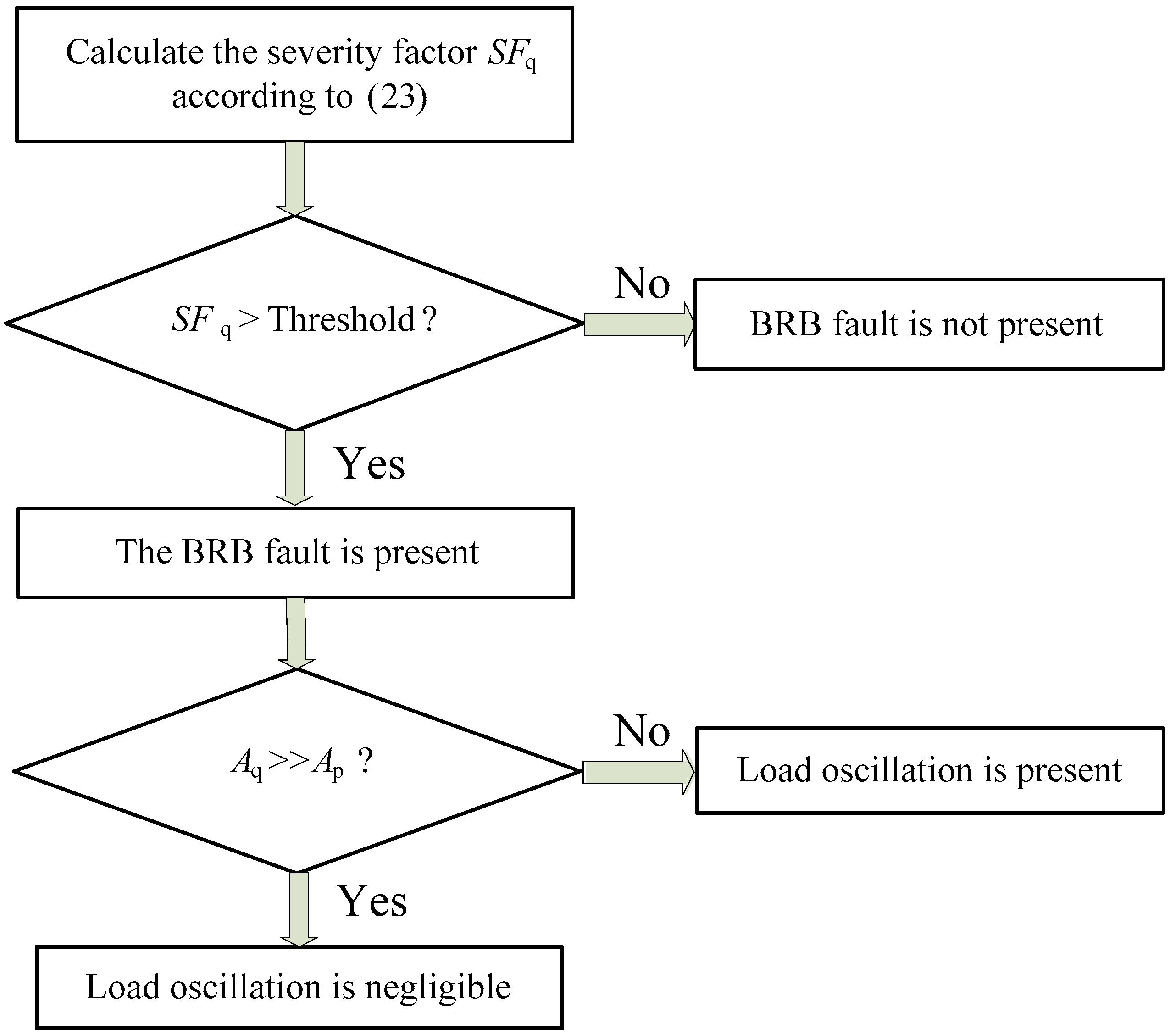
Thus, the criterion for diagnosing load oscillation is present or not can be established as: if Aq >> Ap, then load oscillation is negligible; otherwise, load oscillation is present.
The above work yields a novel strategy for correctly discerning BRB fault and load oscillation even simultaneously present, outlined in Figure 1.
3.2. The Use of ESPRIT
As mentioned above, ESPRIT can easily achieve a high frequency resolution even with a short acquisition time and thus, is definitely superior over FFT, which was taken in Reference [10,11,12,13,14,15] as the benchmark technique for spectral analysis. Therefore, ESPRIT is adopted in this paper as the benchmark technique rather than FFT to conduct the spectral analysis of the IRP and IAP for a certain improvement compared to the existing methods presented in Reference [10,11,12,13,14,15].
In fact, ESPRIT has been successfully adopted to improve the BRB fault detection [6,7,18]. Especially, by adopting ESPRIT rather than FFT to conduct the spectral analysis of the Hilbert modulus, significant improvements have been noted in Reference [18]. Note that the IRP and IAP both share the same frequency-composition with the Hilbert modulus. As an example, they all contain the DC component and the 2sfs component, which is related to BRB fault. The background in this paper is also same as that in Reference [18] in terms of monitoring the 2sfs components and thus, diagnosing BRB fault is present or not. It can thus be inferred that a certain improvement can be expected by adopting ESPRIT rather than FFT to conduct the spectral analysis of the IRP and IAP for discerning BRB fault and load oscillation.
The basics of ESPRIT have been established in Reference [20,21,22]. The implementation procedure of ESPRIT for detecting BRB fault has been described in Reference [6,7,18]. Refer to them for detailed information about ESPRIT.
It is worth mentioning that, besides ESPRIT, quite a few advanced signal-processing techniques have been adopted for improving the BRB fault detection, such as ZFFT in Reference [4], MUSIC and ZSC in Reference [5] and Taylor-Kalman filters in Reference [8]. A comprehensive review on this can be found in Reference [23]. In the future work, all these techniques will be successively tried.
3.3. The Improved Method for Discerning BRB Fault and Load Oscillation
Based on the above work, an improved method for discerning BRB fault and load oscillation is proposed. The basic steps used are as follows:
- (1)
- Calculate the IRP q and remove the DC component, yielding the pulsating component Δq.
- (2)
- Calculate the IAP p and remove the DC component, yielding the pulsating component Δp.
- (3)
- Conduct ESPRIT on Δq, yielding the ESPRIT spectrum ΔqESPRIT.
- (4)
- Conduct ESPRIT on Δp, yielding the ESPRIT spectrum ΔpESPRIT.
- (5)
- Investigate ΔqESPRIT to identify the possible 2sfs and fL peaks, labeled as ΔqBRB and ΔqLO, respectively. Note that the former should be greater in amplitude than the latter if they are both present.
- (6)
- Investigate ΔpESPRIT to identify the possible fL and 2sfs peaks, labeled as ΔpLO and ΔpBRB, respectively. Note that the former should be greater in amplitude than the latter if they are both present.
- (7)
- (8)
- Otherwise, it means that fL is approximately or absolutely equal to 2sfs, the strategy outlined in Figure 1 is then recommended.
As demonstrated by Finding (a), the first decision in Figure 1 will satisfactorily achieve the diagnosis on the presence of BRB fault, no matter load oscillation is present or not. Moreover, as demonstrated by Finding (b), the second decision in Figure 1 will satisfactorily achieve the diagnosis on the presence of load oscillation. Thus, the correct discernment of BRB fault and load oscillation will be achieved.
4. Simulation and Experimental Validation
Simulation and experimental results are provided in this section to validate the proposed method. Herein, the adverse case that BRB fault and load oscillation are simultaneously present is addressed.
The test motor is a small induction motor, typed Y100L-2 and rated at 3 kW, 380 V, 50 Hz and 2880 r/m.
The results were sampled up to 10,000 hits with a sampling frequency of 1000 Hz and then, analyzed by means of FFT and ESPRIT, respectively.
The simulation is based on the multiple-coupled-circuit theory, in which the motor is assumed ideal with symmetrical construction, sinusoidal distributed windings and so forth. Detailed information can be referred to [1,3].
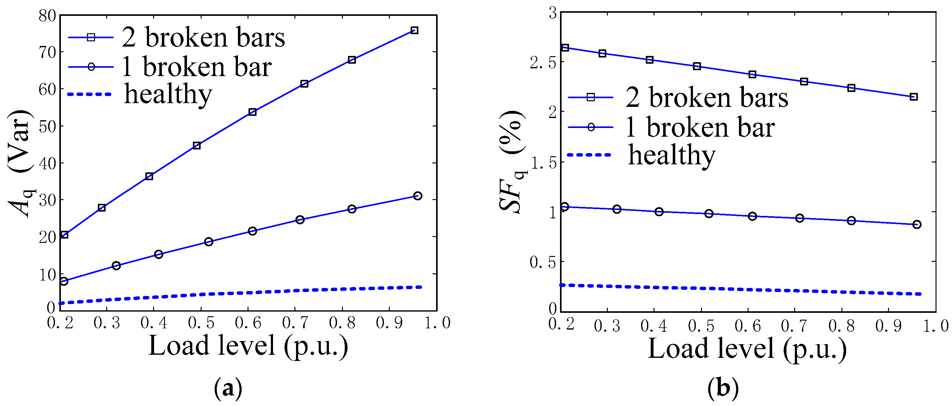
Initially, the simulation is set under the condition that load oscillation is not present to obtain the relationship of Aq versus the number of broken rotor bars and the load level, as shown in Figure 2a. Meanwhile, the relationship between SFq and these two factors is obtained, as shown in Figure 2b. Pay attention that both of Aq and SFq are definitely zero in the case of healthy motor here assumed ideal.
The simulation is then set under the condition that the motor operates with one broken rotor bar, 50% rated load and an oscillating load complying with (6), where TP is fixed at 2.5% rated load, fL and (αT + δ) are set to be 1.56 Hz and π/2, respectively. Note that 2sfs is 1.56 Hz under this condition and thus, fL is actually set to be absolutely equal to 2sfs.
Figure 3 shows the corresponding results. The FFT spectra of the IRP and IAP are given in Figure 3a,b, respectively. In the meantime, the ESPRIT spectra of the IRP and IAP are given in Figure 3c,d, respectively.
Note that the DC components in the IRP and IAP have been pre-filtered out to highlight the interested 2sfs and fL components.
As can be seen from Figure 3, Aq ≈ 57 Var, Ap ≈ 71 W and thus, it does not stand that Aq >> Ap, the criterion used in Reference [10,11,12,13] to indicate the presence of BRB fault. Therefore, the existing methods presented in Reference [10,11,12,13] will give a false diagnosis that BRB fault is not present.
In addition, Pq − Pp is calculated to be about π/9 for the simulated condition. This is significantly different from the criteria of |Pq − Pp| ≈ π/2 and Pq − Pp ≈ π to indicate the presence of BRB fault and load oscillation, respectively. Thus, although the phase information is used as an auxiliary, the method presented in Reference [11] fails.
In fact, as can be seen from (18), (19) and (20), Pq − Pp is stochastic since δ is actually stochastic. Therefore, in the authors’ opinion, the phase information is not suitable for discerning BRB fault and load oscillation.
This instance demonstrates the aforementioned drawback: the existing methods for discerning BRB fault and load oscillation could fail in the adverse case that BRB fault and load oscillation are simultaneously present.
Now evaluate the improved method proposed in this paper. According to Figure 2b, the threshold for the BRB fault detection can be set as 2.0%. Note that such a threshold is noticeably larger than the SFq in the case of healthy motor and in the meantime, noticeably smaller than the SFq in the case of one broken rotor bar. Thus, it is appropriate to guarantee the sensitivity and reliability of the BRB fault detection. Here SFq = Aq/Pav × 100% = 57.14/1421.2 × 100% = 4.02% is greater than the threshold of 2.0%. Thus, the first decision in Figure 1 will reach the correct diagnosis that BRB fault is present. Meanwhile, the second decision in Figure 1 will correctly indicate the presence of load oscillation since Aq (≈57 Var) is not greater than Ap (≈71 W). Therefore, the proposed method achieves the correct discernment of BRB fault and load oscillation, which are simultaneously present, even in the most adverse case that fL is absolutely equal to 2sfs. Certainly, this is a great improvement compared to the existing methods presented in Reference [10,11,12,13,14,15].
In addition, as can be seen from Figure 3, the ESPRIT spectra exhibit a clearer visibility than the FFT spectra, demonstrating that ESPRIT is preferable to FFT in terms of frequency resolution.
Experiments were conducted to further evaluate the proposed method. The test bench is composed of the test motor and a DC generator as the load, as shown in Figure 4a. BRB fault is emulated by drilling off the rotor bar in the region close to the end-ring joint where BRB fault usually starts, as depicted in Figure 4b,c. The load level can be set by adjusting the resistor bank connected to the armature terminals and the field voltage of the DC generator. In the experiments, the needed oscillating load is generated by a customized control system. It is composed of two adjustable resistors (R1 and R2) and an electronic switch (MOSFET) controlled by the digital output pulse of a DSP (OMAP-L138), as shown in Figure 4d. The needed Tp and fL can be obtained by adjusting R1 in accordance with R2 and the MOSFET switching frequency, respectively.
The relationship of Aq versus the number of broken rotor bars and the load level is shown in Figure 5a. Meanwhile, the relationship between SFq and these two factors is shown in Figure 5b.
According to Figure 5b, the threshold for the BRB fault detection can be set as 0.5%, noticeably larger than that in the case of no broken rotor bar and in the meantime, noticeably smaller than that in the case of one broken rotor bar. Such a threshold can guarantee the sensitivity and reliability of the BRB fault detection.
The test was set under the condition that the motor operated with one broken rotor bar, 50% rated load. An oscillating load complying with (6) was introduced, where the amplitude TP was fixed at 3.0% of rated torque and the oscillating frequency fL was set as 1.53 Hz. Under this condition, 2sfs was approximately 1.50 Hz.
Figure 6 shows the experimental results. The FFT spectra of the IRP and IAP are given in Figure 6a,b, respectively. For comparison, the ESPRIT spectra of the IRP and IAP are given in Figure 6c,d, respectively.
As can be seen from Figure 6, Aq ≈ 26 Var, Ap ≈ 63 W and thus, Aq >> Ap used in Reference [10,11,12,13] to indicate the presence of BRB fault does not stand. Therefore, the existing methods presented in Reference [10,11,12,13] fails to give the correct diagnosis that BRB fault is present.
Again, the aforementioned drawback is demonstrated: the existing methods for discerning BRB fault and load oscillation could fail in the adverse case that BRB fault and load oscillation are simultaneously present.
Certainly, the improved method proposed in this paper succeeds. Here SFq = Aq/Pav × 100% = 25.55/1640.4 × 100% = 1.56% is greater than the pre-set threshold of 0.5%. Thus, the first decision in Figure 1 will reach the correct diagnosis that BRB fault is present. Meanwhile, the second decision in Figure 1 will correctly indicate the presence of load oscillation since Aq (≈26 Var) is not greater than Ap (≈63 W). Therefore, the proposed method achieves the correct discernment of BRB fault and load oscillation, which are simultaneously present, even fL is approximately equal to 2sfs. Certainly, this is a great improvement compared to the existing methods presented in Reference [10,11,12,13].
In addition, as can be seen from Figure 6a,b, the FFT spectra fail to discern the fL and 2sfs peaks. However, as can be seen from Figure 6c,d, the ESPRIT spectra achieve to correctly discern them. Herein, Aq >> Ap at 2sfs (1.49 Hz), indicating the presence of BRB fault. Meanwhile, Ap >> Aq at fL (1.53 Hz), indicating the presence of load oscillation. Thus, the correct discernment of BRB fault and load oscillation is achieved. This ascribes to the superiority of ESPRIT over FFT in terms of frequency resolution.
A series of experimental results demonstrate that the ESPRIT spectra of the IRP and IAP can always correctly discern the simultaneously-present 2sfs and fL peaks, as long as the gap between them is not lesser than 0.04 Hz. This means a certain improvement compared to the FFT spectra. However, this kind of improvement is limited, since the ESPRIT spectra still fail to discern the fL and 2sfs peaks in the most adverse case that fL is absolutely equal to 2sfs, as can be seen from the simulation results, Figure 3c,d. Certainly, such a case is seldom encountered from the engineering point of view and thus, ESPRIT is still preferable to FFT.
5. Discussion
As stated above, this paper adopts ESPRIT to get a certain improvement for discerning BRB fault and load oscillation. The theoretical background of ESPRIT has been clearly stated in Reference [20,21,22], as well as the detailed implementation for detecting BRB fault in Reference [18]. However, it is still necessary to highlight a couple of points on ESPRIT.
The first point lies on the data length of q and p directly handled by ESPRIT because it greatly determines the involved computational burden. In this work, the data length of q and p calculated by means of the sampled stator voltage and current signal is up to 10,000 hits with a sampling frequency of 1000 Hz. However, a decimated-down-sampling is applied to q and p before conducting ESPRIT in order to reduce the computational burden. Thus, the data length of q and p directly handled by ESPRIT is just 1000 hits with a sampling frequency of 100Hz. Note that it is reasonable since the interested components in q and p appear at the definitely very low frequency of 2sfs.
The second point lies on the estimation of the signal subspace dimension. Actually a prior knowledge of the signal subspace dimension is definitely required for conducting ESPRIT and thus, it must be pre-estimated. In fact, this problem has already been resolved in Reference [7,18] based on the eigenvalue analysis of the autocorrelation matrix, noticing that the number of the derived main eigenvalues denotes the signal subspace dimension. This paper adopts this kind of method and sees satisfactory results.
6. Conclusions
This paper addresses to discern BRB fault and load oscillation in induction motors.
Many methods existing in the open literature perhaps fail in the adverse case that BRB fault and load oscillation are simultaneously present and especially, perforce fail in the most adverse case that fL is absolutely equal to 2sfs. To resolve this problem, an improved method for discerning BRB fault and load oscillation is proposed in this paper.
On the one hand, the theoretical basis for discerning BRB fault and load oscillation is extended to include the adverse case that these two phenomena are simultaneously present, for the first time. Such work yields some important findings on the fL and 2sfs peaks in the IRP and IAP spectra. A novel strategy is thus outlined, which can correctly discern BRB fault and load oscillation even simultaneously present.
On the other hand, ESPRIT is adopted to analyze the IRP and IAP, yielding a certain improvement compared to the existing methods adopting FFT.
The above work yields an improved method for discerning BRB fault and load oscillation, which has been validated with simulation and experimental results.
Author Contributions
Conceptualization, L.S. and B.X.; Methodology, B.X.; Software, B.X.; Validation, L.S. and B.X.; Formal analysis, B.X.; Investigation, L.S.; Resources, L.S.; Data curation, B.X.; Writing—original draft preparation, L.S.; writing—review and editing, L.S. and B.X. Visualization, L.S.; Supervision, B.X.; Project administration, B.X.; Funding acquisition, B.X.
Funding
This research was supported in part by National Natural Science Foundation of China, grant number 51277077.
Acknowledgments
The authors would like to acknowledge Jinbo Li and Shihua Tian for their help in designing and conducting the experiments.
Conflicts of Interest
The authors declare no conflict of interest.
References
- Toliyat, H.A.; Lipo, T.A. Transient analysis of cage induction machines under stator, rotor bar and end ring faults. IEEE Trans. Energy Convers. 1995, 10, 241–247. [Google Scholar] [CrossRef]
- Jung, J.-H.; Lee, J.-J.; Kwon, B.-H. Online diagnosis of induction motors using MCSA. IEEE Trans. Ind. Electron. 2006, 53, 1842–1852. [Google Scholar] [CrossRef]
- Jerkan, D.G.; Reljić, D.D.; Marčetić, D.P. Broken rotor bar fault detection of IM based on the counter-current braking method. IEEE Trans. Energy Convers. 2017, 32, 1356–1366. [Google Scholar] [CrossRef]
- Bellini, A.; Yazidi, A.; Fillippetti, F.; Rossi, C.; Capolino, G.-A. High frequency resolution techniques for rotor fault detection of induction machines. IEEE Trans. Ind. Electron. 2008, 55, 4200–4209. [Google Scholar] [CrossRef]
- Mo-Sotelo, D.; Romero-Troncoso, R.d.J.; Panagiotou, P.A.; Antonino-Daviu, J.A.; Gyftakis, K.N. Reliable detection of rotor bars breakage in induction motors via MUSIC and ZSC. IEEE Trans. Ind. Appl. 2018, 54, 1224–1234. [Google Scholar] [CrossRef]
- Xu, B.; Sun, L.; Xu, L.; Xu, G. An ESPRIT-SAA-Based detection method for broken rotor bar fault in induction motors. IEEE Trans. Energy Convers. 2012, 27, 654–660. [Google Scholar] [CrossRef]
- Kim, Y.-H.; Youn, Y.-W.; Hwang, D.-H.; Sun, J.-H.; Kang, D.-S. High-resolution parameter estimation method to identify broken rotor bar faults in induction motors. IEEE Trans. Ind. Electron. 2013, 60, 4103–4117. [Google Scholar] [CrossRef]
- Trujillo-Guajardo, L.A.; Rodriguez-Maldonado, J.; Moonem, M.A.; Platas-Garza, M.A. A multiresolution Taylor–Kalman approach for broken rotor bar detection in cage induction motors. IEEE Trans. Instrum. Meas. 2018, 67, 1317–1328. [Google Scholar] [CrossRef]
- Drif, M.; Cardoso, A.J.M. The use of the instantaneous-reactive-power signature analysis for rotor-cage-fault diagnostics in three-phase induction motors. IEEE Trans. Ind. Electron. 2009, 56, 4606–4614. [Google Scholar] [CrossRef]
- Angelo, C.H.D.; Bossio, G.R.; García, G.O. Discriminating broken rotor bar from oscillating load effects using the instantaneous active and reactive powers. IET Electr. Power Appl. 2010, 4, 281–290. [Google Scholar] [CrossRef]
- Cruz, S.M.A. An active–reactive power method for the diagnosis of rotor faults in three-phase induction motors operating under time-varying load conditions. IEEE Trans. Energy Convers. 2012, 27, 71–84. [Google Scholar] [CrossRef]
- Mabrouk, A.E.; Zouzou, S.E.; Sahraoui, M.; Khelif, S. Discriminating time-varying loads and rotor cage fault in induction motors. In Proceedings of the 9th IEEE International Symposium on Diagnostics for Electric Machines, Power Electronics and Drives (SDEMPED), Valencia, Spain, 27–30 August 2013. [Google Scholar]
- Drif, M.; Kim, H.; Kim, J.; Lee, S.B.; Marques Cardoso, A.J. Active and reactive power spectra-based detection and separation of rotor faults and low frequency load torque oscillations. IEEE Trans. Ind. Appl. 2016, 53, 2702–2710. [Google Scholar] [CrossRef]
- Bossio, G.R.; Angelo, C.H.D.; Bossio, J.M.; Pezzani, C.M.; García, G.O. Seperating broken rotor bars and load oscillations on IM fault diagnosis through the instantaneous active and reactive currents. IEEE Trans. Ind. Electron. 2009, 56, 4571–4580. [Google Scholar] [CrossRef]
- Concari, C.; Franceschini, G.; Tassoni, C. Induction machine current space vector features to effectively discern and quantify rotor faults and external torque ripple. IET Electr. Power Appl. 2012, 6, 310–321. [Google Scholar] [CrossRef]
- Kim, H.; Lee, S.B.; Park, S.; Kia, S.H.; Capolino, G.-A. Reliable detection of rotor faults under the influence of low-frequency load torque oscillations for applications with speed reduction couplings. IEEE Trans. Ind. Appl. 2016, 52, 1460–1468. [Google Scholar] [CrossRef]
- Lee, S.B.; Hyun, D.; Kang, T.-J.; Yang, C.; Shin, S.; Kim, H.; Park, S.; Kong, T.-S.; Kim, H.-D. Identification of false rotor fault indications produced by online MCSA for medium-voltage induction machines. IEEE Trans. Ind. Appl. 2016, 52, 729–739. [Google Scholar] [CrossRef]
- Xu, B.; Sun, L.; Xu, L.; Xu, G. Improvement of the Hilbert method via ESPRIT for detecting rotor fault in induction motors at low slip. IEEE Trans. Energy Convers. 2013, 28, 225–233. [Google Scholar] [CrossRef]
- Bellini, A.; Fillippetti, F.; Franceschini, G.; Tassoni, C.; Kliman, G.B. Quantitative evaluation of induction motor broken bars by means of electrical signature analysis. IEEE Trans. on Ind. Appl. 2001, 37, 1248–1255. [Google Scholar] [CrossRef]
- Roy, R.; Paulraj, A.; Kailath, T. ESPRIT—A subspace rotation approach to estimation of parameters of cisoids in noise. IEEE Trans. Acoust. Speech Signal Process. 1986, ASSP-34, 1340–1342. [Google Scholar] [CrossRef]
- Roy, R.; Kailath, T. ESPRIT-estimation of signal parameters via rotational invariance techniques. IEEE Trans. Acoust. Speech Signal Process 1989, 37, 984–995. [Google Scholar] [CrossRef]
- Roy, R.; Kailath, T. Performance analysis of the total least squares ESPRIT algorithm. IEEE Trans. Signal Process. 1991, 39, 1122–1135. [Google Scholar]
- Hassan, O.E.; Amer, M.; Abdelsalam, A.K.; Williams, B.W. Induction motor broken rotor bar fault detection techniques based on fault signature analysis—A review. IET Electr. Power Appl. 2018, 12, 895–907. [Google Scholar] [CrossRef]
Figure 1.
Flowchart for discerning BRB fault and load oscillation.

Figure 2.
Simulation results, the relationships of Aq and SFq versus the number of broken rotor bars and the load level. (a) Aq. (b) SFq.
Figure 2.
Simulation results, the relationships of Aq and SFq versus the number of broken rotor bars and the load level. (a) Aq. (b) SFq.

Figure 3.
Simulation results, fL = 1.56Hz = 2sfs. (a) FFT spectrum of the IRP. (b) FFT spectrum of the IAP. (c) ESPRIT spectrum of the IRP. (d) ESPRIT spectrum of the IAP.
Figure 3.
Simulation results, fL = 1.56Hz = 2sfs. (a) FFT spectrum of the IRP. (b) FFT spectrum of the IAP. (c) ESPRIT spectrum of the IRP. (d) ESPRIT spectrum of the IAP.

Figure 4.
Test bench. (a) Motor loaded with a DC generator. (b) Faulty rotor with one broken rotor bar. (c) Faulty rotor with two broken rotor bars. (d) Customized system for generating the needed oscillating load.
Figure 4.
Test bench. (a) Motor loaded with a DC generator. (b) Faulty rotor with one broken rotor bar. (c) Faulty rotor with two broken rotor bars. (d) Customized system for generating the needed oscillating load.

Figure 5.
Experimental results, the relationships of Aq and SFq versus the number of broken rotor bars and the load level. (a) Aq. (b) SFq.
Figure 5.
Experimental results, the relationships of Aq and SFq versus the number of broken rotor bars and the load level. (a) Aq. (b) SFq.

Figure 6.
Experimental results, fL = 1.53Hz. (a) FFT spectrum of the IRP. (b) FFT spectrum of the IAP. (c) ESPRIT spectrum of the IRP. (d) ESPRIT spectrum of the IAP.
Figure 6.
Experimental results, fL = 1.53Hz. (a) FFT spectrum of the IRP. (b) FFT spectrum of the IAP. (c) ESPRIT spectrum of the IRP. (d) ESPRIT spectrum of the IAP.

© 2018 by the authors. Licensee MDPI, Basel, Switzerland. This article is an open access article distributed under the terms and conditions of the Creative Commons Attribution (CC BY) license (http://creativecommons.org/licenses/by/4.0/).
Share and Cite
MDPI and ACS Style
Sun, L.; Xu, B. An Improved Method for Discerning Broken Rotor Bar Fault and Load Oscillation in Induction Motors. Energies 2018, 11, 3130. https://doi.org/10.3390/en11113130
AMA Style
Sun L, Xu B. An Improved Method for Discerning Broken Rotor Bar Fault and Load Oscillation in Induction Motors. Energies. 2018; 11(11):3130. https://doi.org/10.3390/en11113130
Chicago/Turabian StyleSun, Liling, and Boqiang Xu. 2018. "An Improved Method for Discerning Broken Rotor Bar Fault and Load Oscillation in Induction Motors" Energies 11, no. 11: 3130. https://doi.org/10.3390/en11113130
Note that from the first issue of 2016, this journal uses article numbers instead of page numbers. See further details here.