Article

Introduction of DMD Method to Study the Dynamic Structures of a Three-Dimensional Centrifugal Compressor with and without Flow Control

College of Energy and Power Engineering, Nanjing University of Aeronautics and Astronautics, Nanjing 210016, China
*
Author to whom correspondence should be addressed.
Energies 2018, 11(11), 3098; https://doi.org/10.3390/en11113098
Submission received: 8 October 2018 / Revised: 26 October 2018 / Accepted: 5 November 2018 / Published: 9 November 2018

Abstract

:
The flow structures around the blade tip, mainly large-scale leakage vortex, exert a great influence on compressor performance. By applying unsteady jet control technology at the blade tip in this study, the performance of the compressor can be greatly improved. A numerical simulation is conducted to study the flow characteristics of a centrifugal compressor with and without a flow control. The complex flow structures cause great difficulties in the analysis of the dynamic behavior and flow control mechanism. Thus, we introduced a dynamic flow field analysis technology called dynamic mode decomposition (DMD). The global spectrums with different global energy norms and the coherent structures with different scales can be obtained through the DMD analysis of the three-dimensional controlled and uncontrolled compressors. The results show that the coherent structures are homogeneous in the controlled compressor. The leakage vortex is weakened, and its influence range of unsteady fluctuation is reduced in the controlled compressor. The effective flow control created uniform vortex structures and improved the overall order of the flow field in the compressor. This research provides a feasible direction for future flow control applications, such as transferring the energy of the dominant vortices to small-scale vortices.

1. Introduction

A semi-open centrifugal compressor allows for a high linear velocity, so that a single-stage centrifugal compressor can achieve a high-pressure ratio, which makes it widely used for different applications. However, the design of a high-speed semi-open impeller results in a gap between the casing and blade. The fluid in the gap on both sides of the blade is driven by pressure difference, which will form a strong leakage. Large-scale leakage vortex will then be induced, which will mix with the mainstream and cause energy loss inside the compressor.
In the 1970s, Panpreen [1] discovered that the existence of tip clearance affects compressor performance, and the problematic effects are related to the compressor size, gap ratio, and viscous losses. This study showed that the performance reduction factors increase in small compressors with a high gap ratio. Mashimo [2] investigated the effect of gap height on the performance of a centrifugal compressor. The results showed that the compressor efficiency decreases by 4% when the gap proportion increases from 0.0125 to 0.125. This study also determined the relation between the leakage loss, Reynolds number, and gap’s height. In 1990, Ishida [3] measured the pressure at the impeller cover and concluded that the loss of the tip clearance is related to the gap proportion, and the blockage caused the decrease in relative velocity.
Previous researchers realized that the blade tip clearance causes an aerodynamic loss in a centrifugal compressor and affects the stability margin of the compressor. Although the effects of clearance leakage on the performance of a centrifugal compressor have been explained through theoretical research and experimental verification with applicable laws, the explanation of its gas dynamic mechanism remains shallow. Since the early 21st century, researchers have focused on the study of flow structures around the blade tip, with a further understanding of the flow phenomenon. These studies investigated important phenomena related to the leakage vortices.
In 2003, Ibaraki [4] from the Mitsubishi Company studied the flow structure around the blade tip of a transonic centrifugal compressor through numerical simulation and vortex identification. The tip of the main blade showed a clear leakage vortex structure, and the roll up of the leakage vortex causes a strong total pressure loss. He believed that a large low-velocity region that formed around the blade tip was closely related to the flow structure around the blade tip. Another study by Takahashi [5] found two strands of leaking vortices on the side of the suction surface of the main blade. The two strands of leakage vortices cause considerable energy loss. Takahashi concluded that the two leakage vortices under the influence of adverse pressure gradient break down, thereby causing a large blockage in the tip area of the channel.
Other research also found that the flow structures at the blade tip, mainly the tip leakage vortex, exert great influence on the compressor performance [6,7,8]. In some cases, the tip leakage vortices show obvious unsteady characteristics [9,10,11], which may be related to the dynamic characteristics of the tip leakage vortices. On this basis, some flow control methods can be applied to suppress the tip leakage vortices and improve the compressor performance. Han from NASA (National Aeronautics and Space Administration) [12] studied a transonic axial compressor by experiment and numerical simulation. He placed monitoring points on the casing wall. After applying fast Fourier transform (FFT) of the measured pressure, the spectrum exhibited two periodic characteristics, namely, 40–60% blade rotation frequency and 40–60% blade passage frequency (BPF). The former reflects the operation of the blocking mass in the blade passage, whereas the latter reflects the unstable characteristics of the leakage vortex, which is related to the movement of the leakage vortex. According to this study, the fluid in the blade passage will produce a synchronized effect with the leakage vortex oscillation, which will cause flow instability [13]. März [14] found through experiments and numerical studies that the leakage vortex has a dynamic periodic motion form. The velocity of the leakage vortex that moves toward the pressure surface of the adjacent blades by suction is approximately half of the speed of the rotor tip, which causes pressure fluctuation near the casing. This wave will stall the compressor when it enters the adjacent blades.
However, the dynamic behavior of a centrifugal compressor cannot be easily understood because of the complex flow condition inside the compressor. An unsteady numerical result may involve large amounts of data, which would cause significant difficulties for analysis. The information contained in the time–space flow field can be decoupled to determine the main dynamic characteristic of the flow. Proper orthogonal decomposition (POD) [15] has been widely used in recent years [16] for this purpose. The basic idea of POD is to find a set of primitives of a snapshot flow field that can be reconstructed as the sum of the product of this set of orthogonal bases and their respective time weighting coefficients (weighting coefficients distributed over time). The POD method can decompose the original space–time flow field into a coherent structure with a certain energy level. However, POD often acquires the flow field by some statistical average, and loses the phase information of the system. In POD, the vortex structures of different frequencies remain mixed. Thus, the original flow field is difficult to analyze in the dynamic level. Unlike POD, dynamic mode decomposition (DMD) decomposes and extracts the flow field from the dynamic level, and the resulting modes are independent of one another in time. In 2009, Schmid from Paris Polytechnic University and Rowly from Princeton University proposed the DMD method [17,18], which is based on the Koopman analysis of nonlinear systems. The idea of the Koopman analysis is to transfer the study of the original system to the study of the Koopman operator, which contains all of the information of the original dynamical system [18]. The DMD method is an approximation of the Koopman analysis, which provides a new method and perspective to describe the coherent structure of flow.
The DMD method was successfully applied to flow structures in recent years. Schmid [19] extracted the dominant frequency-dependent dynamic modes in a jet using the DMD method. Seena [20] studied cavity flow and found that it would cause a resonance phenomenon (hydrodynamic resonances) when the incoming boundary layer reaches a certain condition. Nastase [21] studied three-dimensional blade emission. They found through the DMD analysis that the Kelvin–Helmholtz structure is the main form of this emission. At present, the DMD method is mainly used to analyze typical periodic unsteady flow, but only a few scholars reported on the unsteady application of a complex compressor and its flow control [16].
In this research, an unsteady numerical simulation is conducted to study the flow characteristics of a centrifugal compressor with and without flow control. The flow characteristics of the centrifugal compressor have been discussed. Based on the numerical simulations, the DMD method is used to analyze the flow field in a compressor with and without unsteady jet flow control technique. The coherent structure of the blade tip flow field is extracted before and after the compressor is controlled. The control mechanism of the effective unsteady excitation on the coherent separation flow is discussed using the results of the DMD analysis.

2. Numerical Simulation and Analysis Method of Compressor

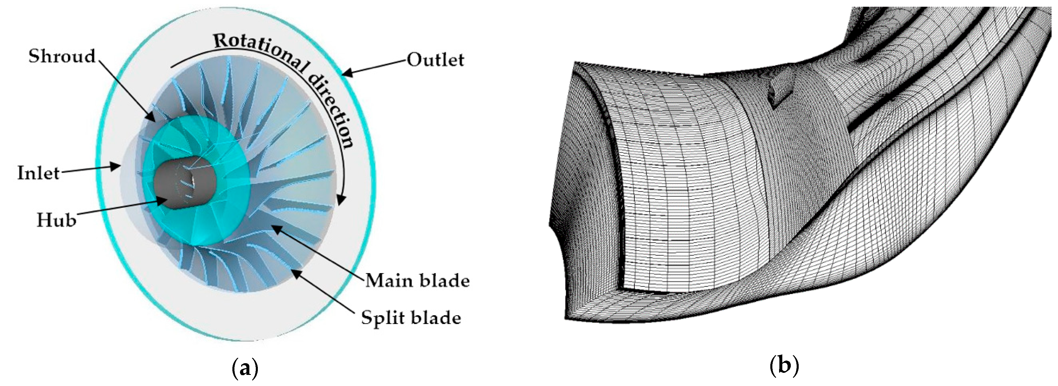
2.1. Investigated Centrifugal Compressor

The investigated centrifugal compressor is used in a closed Brayton cycle power-thermal conversion system [22]. The compressor has 10 main and split blades. The calculation is conducted only for an isolated rotor impeller, so as to avoid the influence of rotor–stator interference on the unsteady characteristics of the compressor. Table 1 shows the details of the impeller.

2.2. Unsteady Numerical Calculation Method for the Compressor

NUMECA/AutoGrid-5 (NUMECA International, Chaussée de la Hulpe, 189, 1170 Brussels) is used for automatic mesh generation in the impeller passage. The mesh is generated using NUMECA/IGG. A structured H-type grid is generated in the main flow region, while around the blade surface, a structured O-type grid is adopted. The total number of grids is approximately 1,800,000. Figure 1 shows the investigated centrifugal compressor and its computational domain (including unsteady flow control). The numerical simulation uses the NUMECA/Fine module to solve the Navier–Stokes equation group of the Reynolds-averaged Navier–Stokes equations. The calculation uses the Spalart–Allmaras turbulence model. The governing equation is discretized by the finite volume method with a two-order central difference scheme. The multigrid technique and implicit residual smoothing technique are used to accelerate convergence. The time step is 5 × 10⁻⁶ s. The initial flow field is carried out on a constant basis to accelerate the unsteady convergence rate. The boundary conditions are set as follows: the inlet total pressure is 101,325 Pa; the inlet total temperature is 288 K; the solid wall has adiabatic no-slip conditions; the outlet is set to a given static pressure. The unsteady calculation converges when the calculating residuals and aerodynamic parameters periodically change. The calculated data after convergence are used for post processing. An unsteady flow control method is adopted at the casing wall. The unsteady control method is realized by opening holes on the casing wall. The driving source is the pressure difference inside and outside the compressor. The details of this unsteady excitation are introduced in another paper [23].

2.3. Introduction to DMD

The DMD method can be used to process and analyze a large number of experimental data or numerical simulation results. The derivation process of the algorithm is presented in the literature [17,18,19]. The current study mainly introduces its basic principle and implementation method. A spatiotemporal velocity field can be written as a vector matrix, V 1 N = [ v 1 , v 2 , , v N ] , where N is the time step and vj is the velocity field at a certain time. The time step between vj and vj+1 is Δt. For a coherent flow structure, a certain relationship is assumed to exist between the flow field at a given moment and that at the previous moment. The velocity field at the latter moment can be approximately linearly represented by the velocity field at the previous moment
V 2 N = A V 1 N 1 ,
where A contains the dynamic information of the original space–time flow field. The dimension of A is generally high (depending on the data points of the flow field) and is thus difficult to solve directly. The dimension of A should be reduced and the eigenvalues and eigenvectors of A must be transformed to the companion matrix of S. A straightforward least-square procedure is employed, and S can be recovered as follows:
S = R 1 Q H V 2 N ,
where Q and R are generated from the QR decomposition of S, and the superscript H means complex conjugate transpose. The matrix form of the dynamic mode of a flow field series can be written as follows:
Φ = V 1 N 1 X ,
where X is the eigenvector matrix of S. The frequency of the ith mode can be expressed as follows:
f i = ω i i / 2 π ,
where ω i i is the imaginary part after the logarithm of the eigenvalue λi of S,
ω i = log ( λ i ) / Δ t = ω i r + i ω i i .

3. Unsteady Flow Characteristics of the Centrifugal Compressor near the Blade Tip

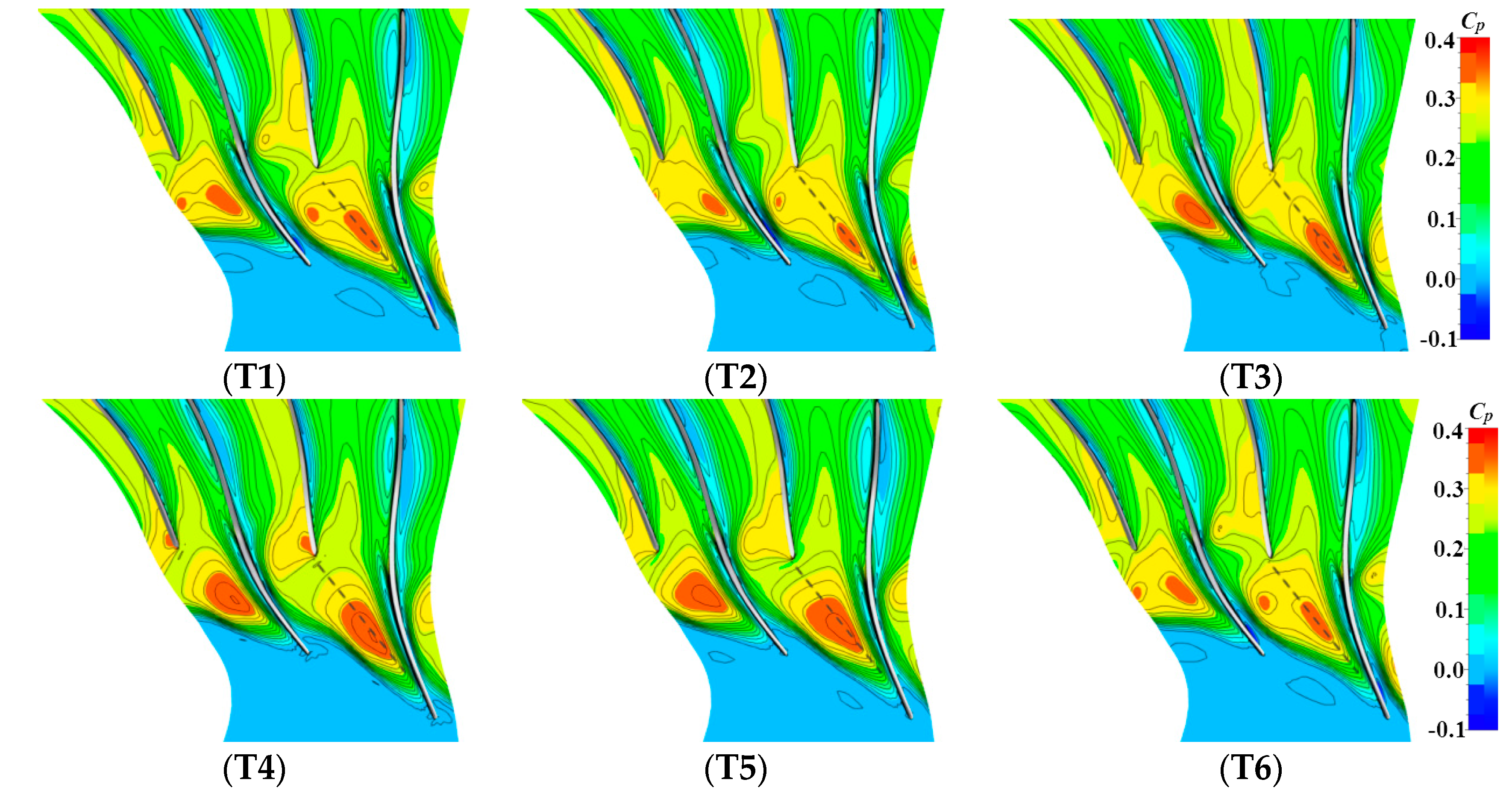
3.1. Quasi-Periodic Variation Flow Field at Blade Tip

An analysis is conducted for the compressor under a near-stall condition, because the unsteady fluctuation is obvious under this condition. The unsteady characteristics of the flow field are determined by the static pressure coefficient. The hydrostatic pressure coefficient is defined as follows:
C p = p ( t ) p in p in ,
where p(t) is the transient static pressure, and pin is the inlet average static pressure. Figure 2 shows the variation in static pressure distribution over time at a 98% blade height. The pressure fluctuation at the tip presents a certain quasi-periodic variation. This quasi-periodic variation is reflected in the main static pressure fluctuations along the dotted line, as shown in Figure 2. The spectrum characteristics of this unsteady change can be obtained by setting some monitoring points at the blade tip and by using FFT [22].

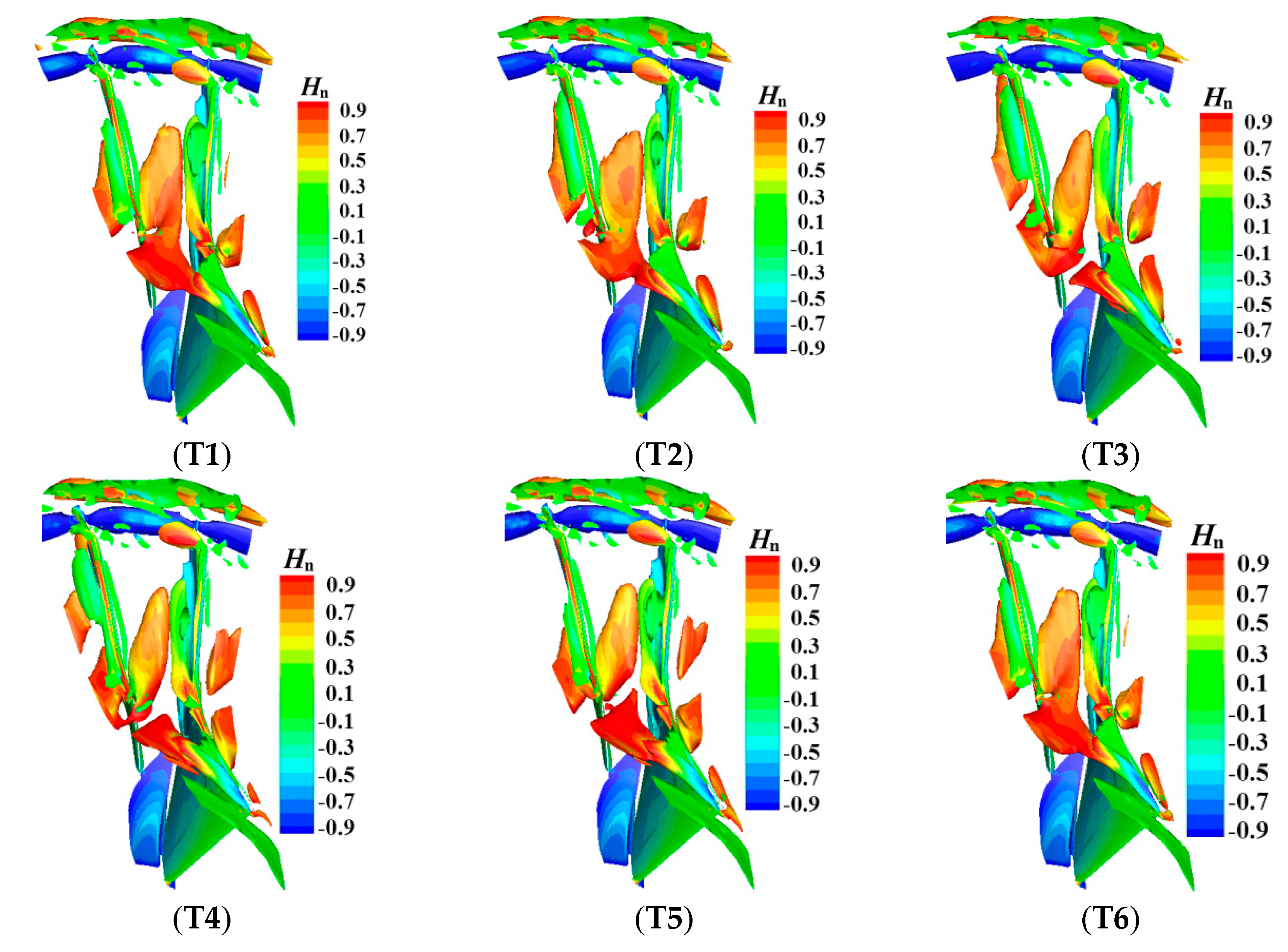
3.2. Variation in the Main Coherent Structures

Although some of the characteristics of the compressor tip flow field can be obtained from the dynamic pressure change diagram, this information is imperfect if the internal flow mechanism is to be understood thoroughly. The flow field can be observed by introducing spatial vortex structure identification techniques, such as the Q criterion vortex identification method [24]. The expression is given as follows:
Q = Ω 2 S 2 2 ,
where Ω is the vorticity tensor and S is the strain rate tensor. The Q criterion vortex identification method can detect the dominant position of the vorticity tensor over the strain rate tensor in the flow field. Thus, it can efficiently identify the vortex structure. Figure 3 shows the dynamic changes in the coherent structure in the compressor, but the intricacy of the various vortices causes it to be difficult to capture some of the important information and flow characteristics that can explain the flow pattern. Therefore, a powerful flow field-processing method is needed.

4. DMD for Centrifugal Compressor with and without Flow Control

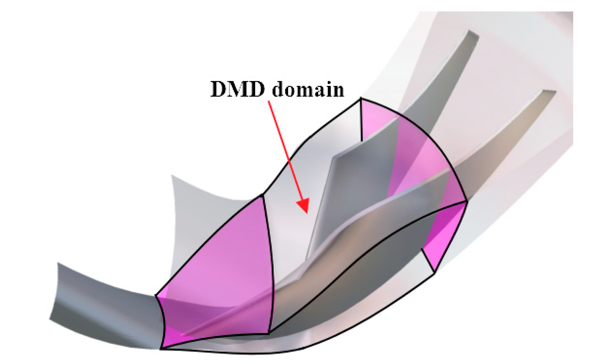
4.1. DMD Method for Three-Dimensional Flow Field of Compressors

The DMD analysis is only for the front part of the compressor blade passage, where the concerned vortices are still included, so as to simplify the calculation. The specific decomposition area is shown in Figure 4. The Q value is decomposed for the results of the numerical simulation in the three-dimensional flow of the compressor, considering the visualization of a mode’s dynamic process. The time interval here for the DMD analysis is 1 × 10⁻⁵ s. A total of 201 moments of the flow field are decomposed, i.e., N = 201. Thus, the matrix, S, has a dimension of 200 × 200. The DMD method facilitates a fast calculation, because the dimension of the matrix S is small. Unlike POD, the dimension of the characteristic matrix of POD is related to the number of grids, and the computation speed is slow. The total analysis time contains approximately 13 cycles of leakage vortex movement (the dominant frequency is 6931 Hz [22]).

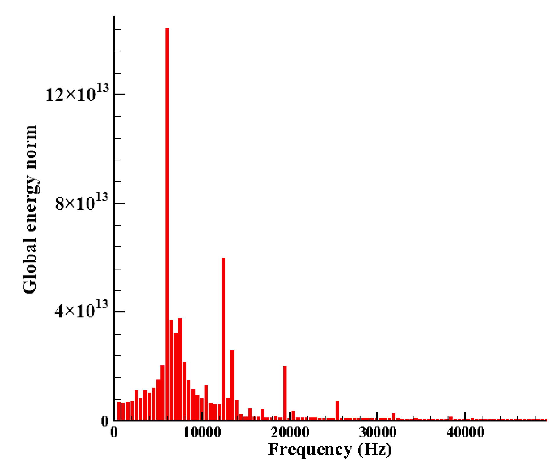
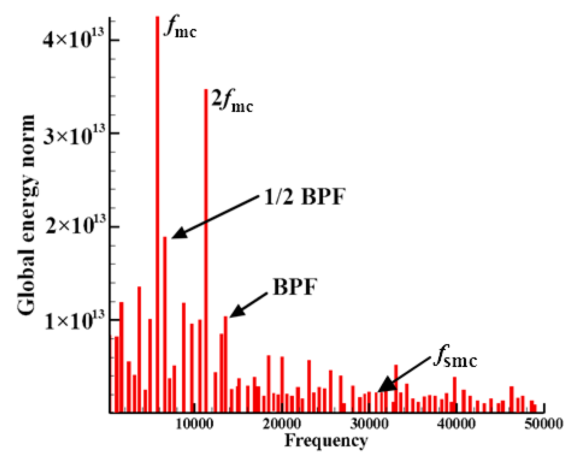
4.2. DMD Spectrum of Controlled and Uncontrolled Compressors

A large number of monitoring points should be set up to acquire the dominant frequency of the complex flow. The flow field is sometimes complex or sensitive to the location of the monitoring points. Thus, the conventional method will become cumbersome. It is possible to avoid the monitoring of single points by using the DMD method. This method grasps the characteristics of the flow field globally. The position of the predominant coherent structure is unknown, but its frequency can be obtained. In addition, the ordinate of the DMD spectrum is the global energy, which roughly reflects the corresponding energy characteristics of a certain mode. Therefore, the energy intensity relationship among the different modes can be rapidly obtained by the DMD spectrum.
Figure 5 and Figure 6 are the DMD spectra of the compressor without and with the control system, respectively. In Figure 5, the maximum peak value appears at 6397 Hz, which corresponds to the main frequency, fm, of the leakage vortex, which is approximately 48% BPF. This ratio is close to Han et al.’s [12,13,14] results, which indirectly verifies the validity of DMD. Peaks also exist in the uncontrolled compressor, in addition to the main frequency, at two-, three-, and four-times higher than the main frequency. The dominant position of the leakage is obvious.
However, the DMD spectrum of the controlled compressor is different from that of the uncontrolled compressor. The dominant frequency in the DMD spectrum of the controlled flow field appears e around 50% BPF (dominant frequency fmc), and the peak value appears at the second harmonic generation. However, the peak values of the third and fourth harmonic generation are no longer obvious, and the clutter component increases. The global energy norm of the dominant frequency is approximately 14.8 × 10¹³ in the uncontrolled state. The global energy norm of the second harmonic generation is approximately 6 × 10¹³. When unsteady excitation is applied, the global energy that corresponds to the dominant frequency decreases to 4.1 × 10¹³, which is smaller than that of the uncontrolled state. The global energy that corresponds to the second harmonic generation is also smaller than that of the uncontrolled state. However, the global energy that corresponds to the clutter component is larger than that of the uncontrolled state. These phenomena show that the dominant position of the leakage vortex decreases and weakens after the effective unsteady flow control is applied. The vortex structures behave uniformly. The proportion of high-frequency components increases, which may be related to the dissipation of the main frequency vortices.

4.3. Dynamic Structures of the Compressor with and without Control

The evolution of a mode obtained by DMD requires one coefficient on this mode. Figure 7 shows the structures of the three-dimensional uncontrolled compressor flow field at different scales as well as their dynamic evolution. The mode that corresponds to frequency fm is Mode-fm, and the mode that corresponds to frequency 2 fm is Mode-2fm. The coherent flow structures with different scales and frequencies have higher frequencies than those with small scales. For Mode-fm, the corresponding trajectory of the red dotted line dominates the development of the coherent structure to Passage-I (between the suction side of the main blade to the pressure side of the split blade). The corresponding trajectory of the green dotted line dominates the development of the coherent structure to Passage-II (between the pressure side of the main blade to the suction side of the split blade). The vortex cluster develops gradually downstream over time. This development is similar to the downward movement of shedding vortices in cascades. The velocity of the three-dimensional vortices and the “shedding” time interval and scale determine the frequency of the dominant coherent structure.
Figure 8 shows a dominant structure comparison of the controlled and uncontrolled compressors. After an unsteady flow control is applied, the coherent structure of the blade tip still shows the unsteady process similar to the vortex “shedding”. A comparison of the controlled dominant mode, Mode-fmc, and the uncontrolled dominant mode, Mode-fm, indicates the following main differences:
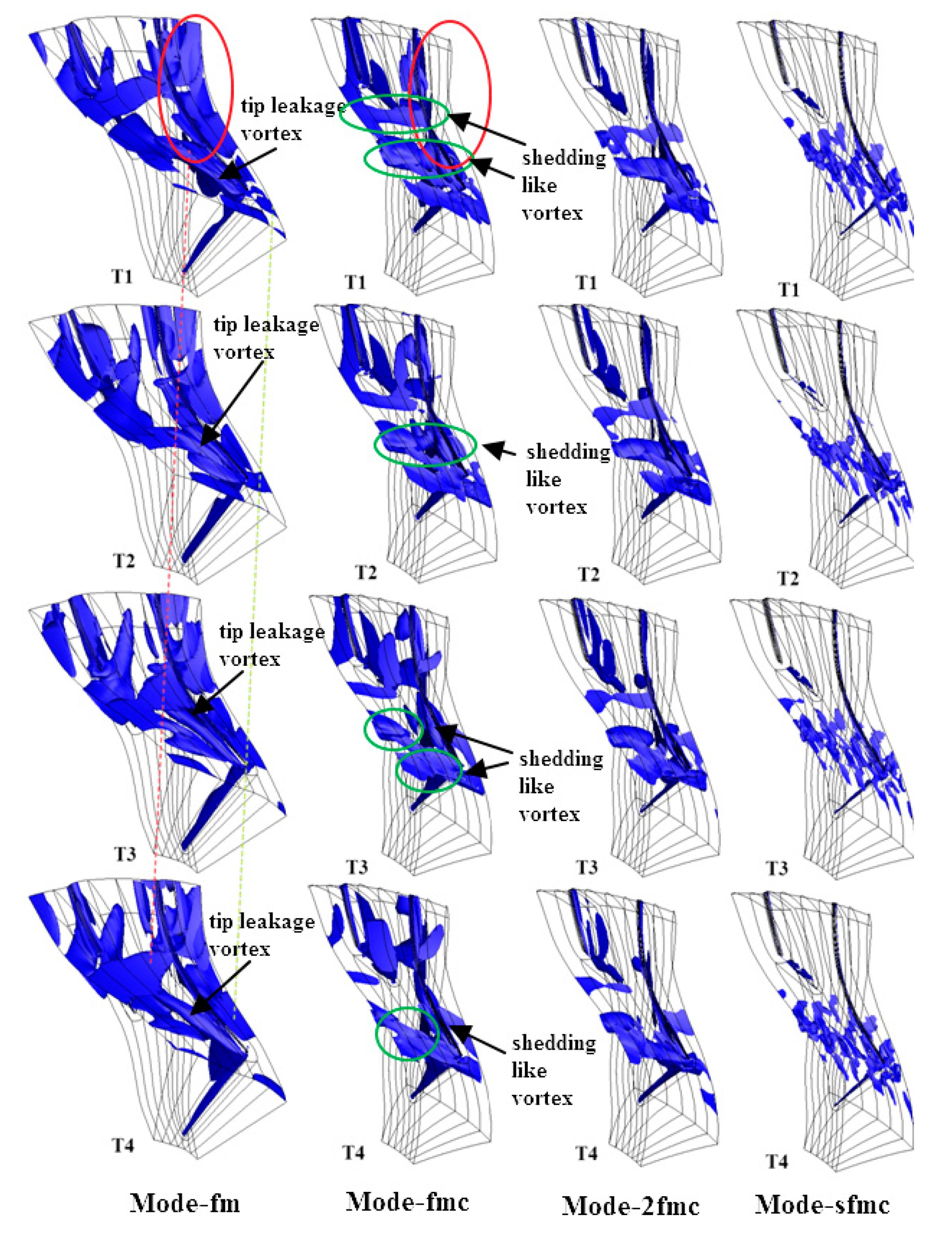
  • The influence area of the dominant mode of the controlled compressor is significantly reduced. The controlled vortices no longer distribute in the passage, especially in Passage-I, as if they are in the uncontrolled state (see the red circle in Figure 8). The influence range of the vortices in Passage-II is also small. In the original flow field, the flow in Passage-I is more turbulent than that in Passage-II. The flow in Passage-I exerts a great impact on the compressor performance. Therefore, the improvement of flow in Passage-I can help to improve the compressor performance.
  • The structure similar to the leakage vortex can still be seen in Mode-fm under a uncontrolled condition. However, the characteristics of the leakage vortex in the Mode-fmc mode were not obvious after being controlled. This phenomenon is mainly manifested by the periodic “shedding” process of the vortices from the leading edge to the downstream development, but no complete leakage vortices are found (see the green circle in Figure 8).
  • For Mode-fm, the flow contains different scales and irregular patterns. However, the irregularity in Mode-fmc decreases, which is mainly manifested by the downstream development of large-scale vortices. Thus, the overall orderliness is high. A comparison of Mode-2fmc that corresponds to the second harmonic generation in the controlled state, and Mode-2fm that corresponds to the second harmonic generation in the uncontrolled state, shows that the order reflected in the second harmonic generation in the controlled state is more obvious. The DMD results show that the effect of unsteady flow control on the structure of small-scale vortices is mainly concentrated in the front half of the passage (from the leading edge of the small blade to the leading edge of the main blade). The influence area of small-scale vortices on the uncontrolled flow field is wide.

5. Conclusions

A microcentrifugal compressor, which is used in a Brayton cycle power-thermal conversion system, has been investigated in this study. The flow field in the compressor passage and the flow field after the periodic excitation control are simulated. The flow characteristics of the centrifugal compressor with and without a flow control has been discussed. In order to analyze the complex flow in the compressor and to get the flow control mechanism, the DMD method is introduced to deal with the dynamic numerical simulation results. The following conclusions are drawn:
(1)
The coherent structure at the blade tip exhibits a quasi-periodic variation and its dominant frequency is approximately half of the BFP (i.e., 50% BPF).
(2)
The DMD spectrum shows that the dominant position of the leakage vortex decreases, the proportion of the high-frequency component increases, and the overall performance of the different vortex structures is uniform.
(3)
The dynamic vortex structure obtained by the DMD analysis shows that the leakage vortex is weakened, the influence range of the unsteady fluctuation is reduced, and the overall order of the flow field is improved.

Author Contributions

S.H. applied the DMD method to the three-dimensional centrifugal compressor with and without flow control. G.H. proposed the concept of unsteady flow control in the compressor. Y.Y. and Z.L. performed the simulations. S.H. and Y.Y. wrote the manuscript.

Acknowledgments

This work was supported by the National Key Basic Research Program of China (973 Program, NO. 2014CB239602).

Conflicts of Interest

The authors declare no conflict of interest.

References

  1. Pampreen, R.C. Small Turbomachinery Compressor and Fan Aerodynamics. J. Eng. Gas Turbines Power 1973, 95, 251–256. [Google Scholar] [CrossRef]
  2. Mashimo, T.; Watanabe, I.; Ariga, I. Effects of fluid leakage on performance of a centrifugal compressor. J. Eng. Gas Turbines Power 1979, 101, 337–342. [Google Scholar] [CrossRef]
  3. Ishida, M.; Ueki, H.; Senoo, Y. Effect of blade tip configuration on tip clearance loss of a centrifugal impeller. Trans. Jpn. Soc. Mech. Eng. 1987, 53, 2099–2103. [Google Scholar] [CrossRef]
  4. Ibaraki, S.; Matsuo, T.; Kuma, H.; Sumida, K.; Suita, T. Aerodynamics of a transonic centrifugal compressor impeller. J. Turbomach. 2003, 125, 473–480. [Google Scholar] [CrossRef]
  5. Takahashi, K.; Furukawa, M.; Ibaraki, S. Vortical Flow Structure and Loss Generation Process in a Transonic Centrifugal Compressor Impeller. In Proceedings of the ASME Turbo Expo 2007: Power for Land, Sea, and Air, Montreal, QC, Canada, 14–17 May 2007. [Google Scholar]
  6. Schleer, M.; Song, S.J.; Abhari, R.S. Clearance effects on the onset of instability in a centrifugal compressor. J. Turbomach. 2006, 130, 993–1003. [Google Scholar]
  7. Wang, X.; Wang, J.; He, F.; Zhang, H. Effect of Relative Movement between the Shroud and Blade on Tip Leakage Flow Characteristics. Energies 2017, 10, 1600. [Google Scholar] [CrossRef]
  8. Liu, Y.; Tan, L.; Wang, B. A Review of Tip Clearance in Propeller, Pump and Turbine. Energies 2018, 11, 2202. [Google Scholar] [CrossRef]
  9. Mailach, R. Rotating Instabilities in an Axial Compressor Originating from the Fluctuating Blade Tip Vortex. ASME Trans. J. Turbomach. 2000, 123, 453–460. [Google Scholar] [CrossRef]
  10. Yamada, K.; Funazaki, K.; Furukawa, M. The Behavior of Tip Clearance Flow at Near-Stall Condition in a Transonic Axial Compressor Rotor. In Proceedings of the ASME Turbo Expo 2007: Power for Land, Sea, and Air, Montreal, QC, Canada, 14–17 May 2007. [Google Scholar]
  11. Mao, X.; Liu, B.; Zhao, H. Numerical Investigation for the Impact of Single Groove on the Stall Margin Improvement and the Unsteadiness of Tip Leakage Flow in a Counter-Rotating Axial Flow Compressor. Energies 2017, 10, 1153. [Google Scholar] [Green Version]
  12. Hah, C.; Voges, M.; Müller, M.W.; Schiffer, H.P. Characteristics of tip clearance flow instability in a transonic compressor. In Proceedings of the ASME Turbo Expo 2010 Power for Land, Sea and Air, Glasgow, UK, 14–18 June 2010. [Google Scholar]
  13. Hah, C.; Bergner, J.; Schiffer, H.P. Tip Clearance Vortex Oscillation, Vortex Shedding and Rotating Instabilities in an Axial Transonic Compressor Rotor. In Proceedings of the ASME Turbo Expo 2008: Power for Land, Sea, and Air, Berlin, Germany, 9–13 June 2008. [Google Scholar]
  14. März, J.; Hah, C.; Neise, W. An Experimental and Numerical Investigation into the Mechanisms of Rotating Instability. In Proceedings of the ASME Turbo Expo 2001, New Orleans, LA, USA, 4–7 June 2001. [Google Scholar]
  15. Lumley, J.L. The structure of inhomogeneous turbulent flows. In Atmospheric Turbulence and Radio Wave Propagation; Nauka: Moscow, Russia, 1967; pp. 166–178. [Google Scholar]
  16. Chen, J.; Lu, W.; Huang, G.; Zhu, J.; Wang, J. Research on Pulsed Jet Flow Control without External Energy in a Blade Cascade. Energies 2017, 10, 2004. [Google Scholar] [CrossRef]
  17. Schmid, P.J. Dynamic mode decomposition of numerical and experimental data. J. Fluid Mech. 2010, 656, 5–28. [Google Scholar] [CrossRef] [Green Version]
  18. Rowley, C.W.; Mezić, I.; Bagheri, S. Spectral analysis of nonlinear flows. J. Fluid Mech. 2009, 641, 115–127. [Google Scholar] [CrossRef]
  19. Schmid, P.J. Application of the dynamic mode decomposition to experimental data. Exp. Fluids 2011, 50, 1123–1130. [Google Scholar] [CrossRef]
  20. Seena, A.; Sung, H.J. Dynamic mode decomposition of turbulent cavity flows for self-sustained oscillations. Int. J. Heat Fluid Flow 2011, 32, 1098–1110. [Google Scholar] [CrossRef]
  21. Nastase, I.; Meslem, A.; Hassan, M.E. Image processing analysis of vortex dynamics of lobed jets from three-dimensional diffusers. Fluid Dyn. Res. 2011, 43, 1073. [Google Scholar] [CrossRef]
  22. Hong, S.; Huang, G.; Lu, W. Study on a Subsonic Micro-Centrifugal Compressor Stall Mechanism. In Proceedings of the ASME Turbo Expo 2017: Turbomachinery Technical Conference and Exposition, Charlotte, NC, USA, 26–30 June 2017. [Google Scholar]
  23. Hong, S. Research on Centrifugal Compressor Technology in Microminiature High Efficiency Brayton Cycle. Ph.D. Thesis, Nanjing University of Aeronautics and Astronautics, Nanjing, China, 2018. [Google Scholar]
  24. Hunt, J.C.R. Eddies Stream, and Convergence Zones in Turbulent Flows; Center for Turbulence Research: Stanford, CA, USA, 1988; pp. 193–208. [Google Scholar]
Figure 1. The three-dimensional centrifugal compressor and its simulation domain: (a) The investigated three-dimensional centrifugal compressor; (b) the simulation domain and its grid.
Energies 11 03098 g001
Figure 2. Variation in static pressure distribution with time.
Energies 11 03098 g002
Figure 3. Variation in vortex structures with time.
Energies 11 03098 g003
Figure 4. Dynamic mode decomposition (DMD) analysis domain.
Energies 11 03098 g004
Figure 5. DMD spectrum of uncontrolled compressor.
Energies 11 03098 g005
Figure 6. DMD spectrum of controlled compressor.
Energies 11 03098 g006
Figure 7. Dominant structure of uncontrolled compressor.
Energies 11 03098 g007
Figure 8. Dominant structure comparison of controlled and uncontrolled compressors.
Energies 11 03098 g008
Table 1. Geometric and aerodynamic parameters of impeller.
Performance ParameterMass flow (kg/s)0.36
Rotational speed (r/min)80,000
Total pressure ratio2.9
Inlet ParameterTip diameter (mm)59.5
Root diameter (mm)19.5
Relative Mach number at blade tip0.87
Relative airflow angle at blade tip (°)30.6
Relative airflow angle at blade root (°)59.3
Outlet ParameterTip diameter (mm)98.5
Width (mm)4.08
Absolute airflow angle (°)30.0
Relative airflow angle (°)71.7

