Advanced Thermodynamic Analysis of a Transcritical R744 Booster Refrigerating Unit with Dedicated Mechanical Subcooling


Department of Energy and Process Engineering, NTNU Norwegian University of Science and Technology, Kolbjørn Hejes vei 1A, 7491 Trondheim, Norway
Energies 2018, 11(11), 3058; https://doi.org/10.3390/en11113058
Submission received: 19 October 2018
/
Revised: 2 November 2018
/
Accepted: 4 November 2018
/
Published: 7 November 2018
(This article belongs to the Section A: Sustainable Energy)
Abstract
:In this work the thermodynamic performance of a transcritical R744 booster supermarket refrigeration system equipped with R290 dedicated mechanical subcooling (DMS) was exhaustively investigated with the aid of the advanced exergy analysis. The outcomes obtained suggested that improvement priority needs to be addressed to the manufacturing of more efficient high-stage (HS) compressors, followed by the enhancement of the gas cooler/condenser (GC), of the medium-temperature (MT) evaporators, of the R290 compressor, and of the low-temperature (LT) evaporators. These conclusions were different from those drawn by the application of the conventional exergy assessment. Additionally, it was found that GC can be enhanced mainly by reducing the irreversibilities owing to the simultaneous interaction among the components. The R290 compressor would also have significantly benefitted from the adoption of such measures, as half of its avoidable irreversibilities were exogenous. Unlike the aforementioned components, all the evaporators were improvable uniquely by decreasing their temperature difference. Finally, the approach temperature of GC and the outdoor temperature were found to have a noteworthy impact on the avoidable irreversibilities of the investigated solution.
1. Introduction
Commercial refrigeration units play a crucial role in modern society, being widely employed for satisfying various human needs. However, supermarket refrigerating applications predominately rely on hydrofluorocarbons (HFCs), such as HFC-404A and HFC-507A, as refrigerants. These working fluids feature a Global Warming Potential (GWP) being thousands of times more environmentally damaging than carbon dioxide, leading the commercial refrigeration sector to be a major direct driver of global warming. To reduce the HFC consumption and, thus, significantly mitigate the carbon footprint of food retail stores in Europe, the EU F-Gas Regulation 517/2014 [1] was issued. This legislative act aims at progressively decreasing the HFC supply by 79% by 2030 in relation to the average levels in 2009–2012. Additionally, the EU F-Gas Regulation 517/2014 imposes a limit in terms of GWP100 years for the refrigerants used in multipack centralized refrigeration systems with a rated capacity above 40 kW equal to 150 since January 2022. The fight against HFCs is intensifying on global perspectives as well, as 197 countries recently agreed to bring the production and consumption of HFCs down by more than 80% over a 30-year period [2]. Therefore, the selection of a long-term refrigerant is becoming arduous for engineers and end-users in as strategic a sector as that of supermarket applications. This challenge is further complicated in warm climates where, for climate reasons, refrigeration reclaim has a considerable impact on economic, energy, and environmental perspectives.
Commercial refrigeration plants using carbon dioxide as the sole refrigerant (R744) are perceived to be one of the most promising candidates with which to replace the currently employed units [3]. Being that R744 is non-flammable, non-toxic, and environmentally friendly (i.e., negligible GWP), in fact, this working fluid is bound not to be subject to any future restrictions. This refrigerant is also readily available and inexpensive, as well as features more favorable thermo-physical characteristics compared to HFCs [4]. However, as CO2 presents a low critical temperature (about 30.98 °C), the heat rejection process through the high pressure heat exchanger (i.e., gas cooler) can commonly take place in transcritical conditions. These running modes feature large differences between rejection and absorption pressure, leading the conventional transcritical R744 supermarket refrigeration systems to have very poor energy efficiencies with a rise in outdoor temperature. As shown in [5], in fact, the aforementioned systems can energetically compete with refrigerating units employing man-made working fluids at external temperatures up to about 25 °C. Therefore, commercial “CO2 only” refrigeration plants need a more sophisticated system architecture so as to perform equivalently to, or better than, HFC-based solutions in warm locations [3]. As a result of the entry into force of the EU F-Gas Regulation 517/2014, many measures with the purpose of enhancing the performance of such HFC-free units at severe running modes have been developed [3], such as:
- the implementation of the recovery of part of the available expansion work via two-phase ejectors [11,12,13], giving rise to a significant enhancement in overall thermodynamic performance. The conventional expansion valve, in fact, is responsible for the largest irreversibilities in basic transcritical CO2 refrigerating cycles [14] and, thus, for the significant penalization in their efficiencies as the cooling medium temperature goes up.
In order to reduce the aforementioned inefficiencies, Fazelpour and Morosuk [14] recommended the adoption of an expedient aimed at reducing the temperature of R744 exiting the gas cooler. As showed in [15], this target can be achieved with the aid of a dedicated mechanical subcooling, which permits the refrigerant to going into the evaporator with a lower quality and, thus, leads to an increment in refrigerating effect. Also, as described by many researchers [16,17,18], an optimal high pressure, which maximizes the coefficient of performance (COP), has to be evaluated as a function of the gas cooler exit temperature as transcritical running modes occur. As revealed in [15], the integration of the dedicated mechanical subcooling also allows decreasing the optimal heat rejection pressure, giving rise to an additional improvement in performance. The benefits from the adoption of a dedicated mechanical subcooling are summarized in Table 1.
Additionally, an in-depth overview on the “CO2 only” solutions using the dedicated mechanical subcooling was recently presented by Llopis et al. [28]. On the one hand, the findings listed in Table 1 reveal that such “CO2 only” supermarket refrigeration plants are expected to offer promising performance in warm locations. On the other hand, it is also possible to notice that conventional energy-based methods are predominately employed for evaluating the performance of the aforementioned systems. This is due to the fact that such assessments offer simplicity with respect to their adoption, as well as intuitive interpretation of the results obtained, favoring their wide adoption. However, the thermodynamic performance of any energy system can be more appropriately evaluated by applying a conventional exergy analysis. Such an evaluation, in fact, allows bringing to light the location, the magnitude, and the sources of the inefficiencies caused by the irreversibilities taking place in the investigated system. More appropriate conclusions aimed at properly evaluating the thermodynamic performance of any energy system can be drawn with the aid of the advanced exergy analysis [29,30,31]. Unlike the conventional exergy evaluation, in fact, the implementation of this thermodynamic tool enables revealing: (1) the real improvement potential associated with the selected system via the assessment of the avoidable exergy destruction of its components; (2) the mutual interdependencies among the system components via the evaluation of their mexogenous exergy destruction. As a consequence, at present the advanced exergy analysis is widely recognized as the most suitable thermodynamic method to adequately evaluate the performance of any energy system. Furthermore, as mentioned above, state-of-the-art transcritical R744 refrigeration systems have taken center stage in as a crucial sector as that of supermarket applications. To the best of the author’s knowledge, a few investigations combining these key research topics are still available and none of these involves “CO2 only” supermarket refrigeration plants outfitted with dedicated mechanical subcooling, as summarized in Table 2. Therefore, this study is intended to take steps towards this scientific gap by appropriately assessing the thermodynamic performance of a promising HFC-free solution, such as the commercial transcritical R744 booster refrigeration system employing a R290 dedicated mechanical subcooling, with the aid of one of the most powerful thermodynamic tools, i.e., the advanced exergy assessment.
First of all, the advanced exergy analysis has been applied by selecting the external temperature of 40 °C as well as the typical operating conditions of the investigated solution, as the ones suggested in the open literature [8]. At a later time, a study involving the effect of the most influential parameters on the performance of the whole system, i.e., the high stage compressor efficiency, the gas cooler/condenser approach temperature, the R744 subcooler exit temperature and the outdoor temperature, has also been implemented. It is worth remarking that the approach temperature of a heat exchanger is defined as the difference between the outgoing hot fluid temperature and the ingoing cold fluid temperature. In addition to the Introduction, the present work presents five additional sections. In Section 2 the investigated solution and the assumptions in common in all the implemented evaluations are described, while the main concepts related to both the conventional and the advanced exergy assessment are presented in Section 3. The results obtained are shown and discussed in Section 4 and Section 5, respectively. Finally, the conclusions are given in Section 6.
2. System Description and Assumptions in Common in All Implemented Analyses
2.1. System Description
A R744 booster refrigeration system with dedicated mechanical subcooling is schematized in Figure 1. The only difference from a conventional booster solution is the presence of a subcooling system (i.e., a self-contained unit) downstream of GC. Its target is to cool down R744 exiting GC (thermodynamic state 2 in Figure 1) by promoting the vaporization of the working fluid (e.g., R290, R1270, R1234ze(E)) flowing through the subcooler equipment (SB) (thermodynamic state 18 in Figure 1), which is typically a plate heat exchanger. In this work the refrigerant employed in the mechanical subcooling loop was R290 [7,8,15,24,26,27]. After SB (thermodynamic state 3 in Figure 1), R744 is throttled (thermodynamic state 4 in Figure 1) and the resulting vapor-liquid mixture enters the liquid receiver in which the two phases are separated. Therefore, the liquid (thermodynamic state 7 in Figure 1) is employed for feeding the MT and LT evaporators (MT evap and LT evap) (thermodynamic states 8 and 9 in Figure 1, respectively). The refrigerant coming out of LT evap (thermodynamic state 10 in Figure 1) is compressed with the aid of the low stage (LS) “booster” compressors (LS compr) (thermodynamic state 11 in Figure 1) and then mixed with the refrigerant leaving MT evap (thermodynamic state 12 in Figure 1) and that removed from the liquid receiver (thermodynamic state 5 in Figure 1) via the vapor-by pass valve (VB) (thermodynamic state 6 in Figure 1). Finally, the total amount of the refrigerant is drawn by the HS compressors (HS compr) (thermodynamic state 14 in Figure 1) and compressed to high pressure (HP) (thermodynamic state 1 in Figure 1).
The thermodynamic cycle of a conventional booster system (dashed line) and that of a booster solution with dedicated mechanical subcooling (solid line) are compared in a log(p)-h diagram in Figure 2. In the latter, R744 is cooled down to 15 °C (2–3) in the subcooler before undergoing an isenthalpic expansion due to the HP expansion valve (3–4). On the other hand, in a conventional booster configuration CO2 leaving the gas cooler/condenser is directly throttled (2–4’).
2.2. Assumptions in Common in All Implemented Analyses
The energy performance of the selected solution was exhaustively investigated in [8] by selecting realistic operating conditions of a typical supermarket refrigeration system. For this reason, the same running modes as in [8] were adopted in this study. As presented in Table 3, the temperature of R744 leaving the subcooler equipment was taken as 15 °C, as a result of the optimization procedure implemented by Gullo et al. [8]. The authors, in fact, showed that the energy saving achievable by adopting a lower value is negligible. However, at a later time, the influence of this parameter on the performance of the overall system was also investigated. In addition, the values of the air temperature presented in Table 3 were selected as suggested in [32]. Additionally, the procedure used for estimating the values of the optimal heat discharge pressure in all the implemented assessments was exhaustively described in [8].
3. Exergy Analyses
3.1. Conventional Exergy Analysis
Exergy is the maximum useful work which can be derived from bringing the investigated system into thermodynamic equilibrium with the surroundings as a consequence of a thermodynamic interaction only with this. Additionally, the evaluation of the exergy destruction () of a component belonging to the investigated system permits assessing the source of thermodynamic irreversibilities. In the present study, for each component was calculated by relying on the same approach as the one adopted by Morosuk and Tsatsaronis [41], being well-recognized experts in the conventional exergy evaluation and the pioneers of the advanced exergy analysis. In particular, being the kinetic, chemical and potential exergy variations negligible for any vapor-compression refrigeration unit and assuming steady state conditions, the exergy destruction rate for the selected component can be computed by applying the exergy balance in Equation (1) [42]:
in which the term T0 represents the temperature (in Kelvin) of the dead state (i.e., selected outdoor temperature), while and indicate the physical exergy per unit of mass respectively related to the inflows and outflows. These can be computed with the aid of Equation (2):
in which the temperature T (in Kelvin) and the pressure p describe a generic thermodynamic state, while po refers to the pressure of the dead state (taken as 1.01 bar). It is important to highlight that the results of the exergy analysis are not influenced significantly by the definition of the dead state [43].
The additional assumptions necessary to carry out the conventional exergy analysis are summarized in Table 4 [8].
Furthermore, the global efficiencies of all the employed compressors were computed by means of the correlations listed in Table 5, which were derived from some manufacturers’ software.
The conventional exergy efficiency (ηexergy) of a vapor-compression refrigeration system can be evaluated through Equation (3):
in which the total exergy loss rate () is owing to the interaction between the surroundings and the system in the form of transfers of matter, heat, and work.
3.2. Advanced Exergy Analysis
The splitting of the exergy destruction rate related to the selected component () into its unavoidable () and avoidable () parts permits determining the real potential enhancements. The unavoidable exergy destruction of the investigated component () identifies the part of inefficiencies which cannot be prevented even if the best available component is being employed owing to technological limitations, such as manufacturing methods, cost and accessibility of materials. Therefore, refers to the remaining exergy destruction as the studied component is designed for the highest thermodynamically possible performance and economically feasible limit. The residual exergy destruction of the selected component is the avoidable part () and, thus, the part of inefficiencies to which the designer should pay attention [34,41,46]. Therefore, the Equation (4) can be formulated:
The unavoidable irreversibilities () can be computed by: (1) implementing a thermodynamic cycle based on the assumptions listed in both Section 2.2 and the third column in Table 6; (2) then calculating the exergy destruction of each component (i.e., ) via Equations (1) and (2), as suggested in [41]. At a later time, for each component can be calculated by subtracting from [41].
Additional key suggestions for the best guidance to explore the thermodynamic performance of energy conversion systems can be derived from the splitting of the inefficiencies in the selected component () into its endogenous () and exogenous () parts, being:
In order to calculate the endogenous destruction rate associated with the selected component (), it is necessary to realize a cycle whose component being considered operates at real conditions and all the remaining components work at theoretical operation conditions (i.e., at if it is possible, otherwise ) [34,41,47]. The number of these cycles, which has to be implemented, is equal to the number of the components of the investigated system. The exogenous exergy destruction associated with the investigated component () is due to the irreversibilities occurring in the remaining components [34,41,47]. In this work, for each component was computed as recommended in [41], i.e., by implementing a thermodynamic cycle for each component in which: (1) the selected component performs according to the assumptions listed in Section 2.2 and Section 3.1, whereas the others work in accordance with the assumptions listed in the second column in Table 6; (2) then computing the exergy destruction of each component (i.e., ) via Equations (1) and (2). At a later time, for each component can be calculated by subtracting from [41].
The components of the exergy destruction mentioned above can be additionally split to enhance the understanding and the detection of the potential irreversibilities, being [34,41]:
in which:
- represents the unavoidable endogenous exergy destruction of the selected component, which cannot be reduced because of the technical limitations associated with the component itself;
- is the unavoidable exogenous exergy destruction of the investigated component, which cannot be decreased due to the technical limitations related to the remaining components;
- identifies the part of inefficiencies associated with the selected component, which can be dropped by improving the component itself;
- refers to the part of the irreversibilities related to the investigated component, which can be reduced by enhancing the remaining components.
To calculate for each component, it was implemented a thermodynamic cycle in which: (1) the selected component was considered as operating at unavoidable conditions (through the selection of the appropriate parameter in the third column in Table 6), whereas all the remaining components were simulated in theoretical operations (through the adoption of the suitable parameter in the second column in Table 6); (2) then calculating the exergy destruction of each component (i.e., ) via Equations (1) and (2) [41]. At a later time, for the investigated component was computed by subtracting from [41], whereas was calculated as the difference between and [41]. Finally, was obtained by subtracting from [41].
The concurrent interactions among three or more components of the evaluated system bring about the so-called mexogenous exergy destruction, which can be quantified via Equation (7) for the selected (i.e., k-th) component () [34,45]:
in which identifies the part of the exogenous exergy destruction of the k-th component generated by the inefficiencies, which occur in the r-th component. In particular, another cycle in which both the investigated component (k-th component) and another (r-th component) are operating at real conditions and the remaining n-2 components are working at ideal running modes has to be implemented to compute [34,48].
As mentioned above, firstly the thermodynamic performance of the solution suggested by Gullo et al. [8] was evaluated at the outdoor temperature of 40 °C with the aid of the advanced exergy analysis. At a later time, the influence of most relevant parameters on the performance of the entire system, i.e., the HS compressor efficiency, the gas cooler/condenser approach temperature, the R744 subcooler exit temperature, and the outdoor temperature, was also assessed.
4. Results
4.1. Results at Outdoor Temperature of 40 °C
4.1.1. Results of Conventional Exergy Analysis
Table 7 shows temperature, pressure, mass flow rate, specific enthalpy, specific entropy and specific flow exergy at the external temperatures of 40 °C of the real thermodynamic cycle.
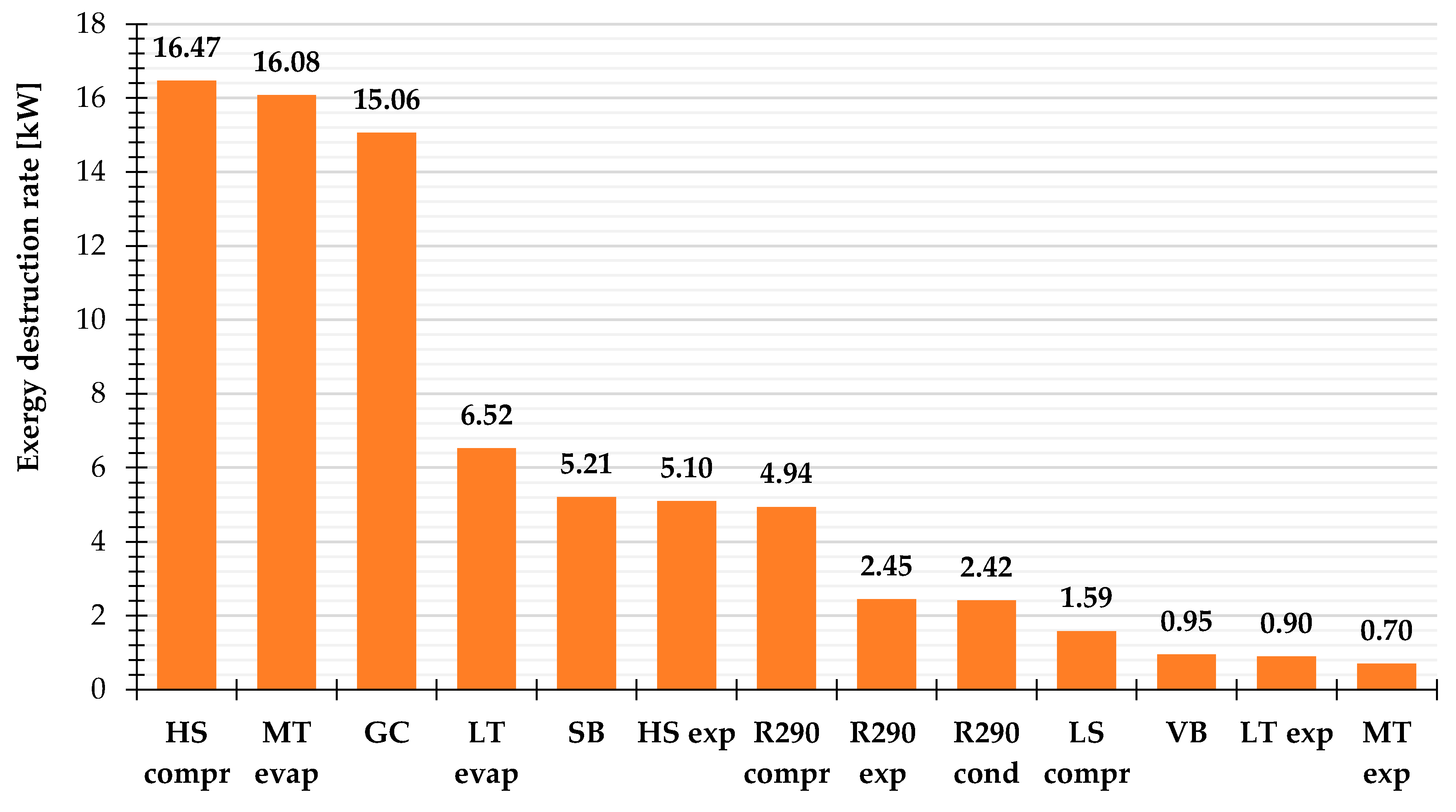
As shown in Figure 3 and further highlighted by Figure 4, the results related to the conventional exergy analysis suggested paying close attention to HS compr, MT evap and GC. These components were responsible for a similar contribution to (i.e., about equal to 20%) at the selected outdoor temperature. In addition, the designer also had to pay close attention to both LT evap ( = 8.2% of ) and SB ( = 6.6% of ). According to [14], the expansion valve downstream of the gas cooler/condenser generates the highest exergy destruction rate of a conventional transcritical CO2 refrigeration machine. In the system under investigation, it was considerably reduced by means of the adoption of the dedicated mechanical subcooling. This induced 6.4% of at the external temperature of 40 °C, similarly to R290 compr. Additionally, the irreversibilities due to the mixing point amounted to about 0.97 kW, while the exergy loss rate was equal to 1.06 kW for GC and to 0.94 kW for R290 cond, respectively. Therefore, the calculated exergy efficiency of the overall system was 0.187 at the evaluated outdoor temperature, the total power input being equal to 100.1 kW.
4.1.2. Results of Advanced Exergy Analysis
Avoidable Endogenous and Exogenous Exergy Destruction
The potential for improvement of the chosen system was mainly associated with the enhancement of the components themselves, since more than two-thirds of the avoidable exergy destruction was endogenous. The further advantageous related to the application of the advanced exergy analysis to the selected solution could be described as follows:
- although HS compr was mainly improvable by enhancing the compressors themselves ( = 71.4% of ), their avoidable exogenous inefficiencies were notable;
- GC presented room for decreasing its exergy destruction via improving the remaining components, being equal to 70.7% of ;
- the conspicuous contribution to on the part of R290 compr could be halved by improving the other components;
- close attention had to be addressed to the enhancement of the other components to decrease the avoidable irreversibilities related to LS compr and SB;
- all the expansion valves had a null component of the avoidable endogenous part.
Finally, it is worth remarking that all the evaporators had a null avoidable exogenous part in accordance with the outcomes in [30,34,41]. This means that only half of the irreversibilities occurring in the evaporators could be actually avoided and only by enhancing the performance of these components themselves.
Interactions among Components
The calculation of the mexogenous part allows understanding how the components of the evaluated system affect one another. As showed in Table 9, the inefficiencies of GC could be brought down mainly by reducing the irreversibilities caused by the simultaneous interaction among the components. Further significant improvements were offered by the enhancement of HS compr due to their high discharge temperature, leading to a significant mismatch between R744 and air through GC. Additionally, as brought to light by the results obtained, the improvement in HS compr could be achieved mainly by increasing their efficiency and then by incrementing its suction pressure (i.e., need for growth in MT). With respect to R290 compr, the outcomes revealed that the inefficiencies owing to the concurrent interaction among the components had to be decreased. Such a component would also have benefitted from the enhancement of GC. The negative value of and suggested worsening the thermodynamic performance of the remaining components to improve both. Additional thermodynamic benefits could be offered to R290 cond by decreasing the temperature difference through MT evap. From Table 9 it is also straightforward that if R744 in GC could have more appropriately fitted the air temperature profile, SB could have experienced significant enhancements in its performance.
4.2. Results of the Sensitivity Analysis
4.2.1. Effect of Efficiency of High Stage Compressors
The previous results demonstrate the need to considerably enhance the efficiency of the high stage compressors. Therefore, the exergy destruction rates of the system investigated above (i.e., DMS) and those related to the same solution featuring an improvement by 10% in ηglob,HS compr (i.e., “Improved” DMS), as suggested in [12], are contrasted in this Subsection. It was found that an increase by 10% in ηglob,HS compr leads to a reduction by 6.6% in and by 11.1% in (Figure 6), respectively. This was strongly depending on the considerable contribution of to , as highlighted by Figure 7 in which the exergy destruction rates of the most affected components are reported. In particular, and related to “Improved” DMS respectively reduced by 28% and by 28.8% compared to the scenario involving DMS. As regards associated with “Improved” DMS, this decreased by 25.8% as a result of the decrement in irreversibilities owing to the simultaneous interaction among the components. Additionally, it was found that the potential implementation of such a measure would permit respectively reducing and related to “Improved” DMS by 13.5% and by 19.1% compared to the reference system, whereas would not experience any changes (Figure 7).
4.2.2. Effect of Gas Cooler/Condenser Approach Temperature
As mentioned above, the performance of “CO2 only” supermarket refrigeration systems is significantly affected by the R744 gas cooler exit temperature in transcritical running modes. Consequently, being this parameter usually computed as the sum of ΔTappr,GC and text [49], the optimal operating conditions are substantially influenced by the approach temperature of the gas cooler. Therefore, in addition to the reference value of 2 K, two further GC approach temperatures respectively equal to 3 and 5 K were chosen. According to the results depicted in Figure 8, the increase in ΔTappr,GC led to an increment in by 2.9% for ΔTappr,GC = 3 K and by 8.2% for ΔTappr,GC = 5 K, as well as in by 1.8% for ΔTappr,GC = 3 K and by 5.3% for ΔTappr,GC = 5 K. On the contrary, was not significantly influenced by the variation in ΔTappr,GC.
Figure 9 shows the influence of the gas cooler/condenser approach temperature on the avoidable endogenous and exogenous exergy destruction rates of the most affected components belonging to DMS at the external temperature of 40 °C. It was revealed that an increase in ΔTappr,GC up to 5 K leads to increments in (due to the deterioration in HS compressor efficiency) and by up to 4.1% and 3.1% compared to the scenario involving ΔTappr,GC = 2 K, respectively. As for GC, the growth in its approach temperature respectively caused a worsening in and by up to 2% and 6.9%. These results can be respectively justified by taking into account the more marked mismatch between R744 and air and the increment in discharge temperature of HS compr. An enormous deterioration in avoidable endogenous and exogenous irreversibilities of both SB and R290 compr, respectively, by up to 55.7% and 29.3% was also observed.
4.2.3. Effect of Outdoor Temperature
As explained in Section 4.2.2, the outdoor temperature plays a pivotal role with respect to the performance of the investigated solution in transcritical operation conditions. Therefore, besides the external temperature of 40 °C, the additional scenario involving text = 45 °C was considered. The corresponding results referring to the influence of this parameter on the avoidable and unavoidable exergy destruction rates of the investigated system are presented in Figure 10. It was found that and respectively increase by 8.3% and 9.6% at text = 45 °C over the outcomes obtained at text = 40 °C.
The avoidable irreversibilities of the most influenced components by the increment in text are estimated in Figure 11. Due to the growth in text, and underwent an increment by 9.1% and 7.4%, respectively. As regards the high pressure heat exchanger, was not significantly affected by the variation in text, whereas increased by 5.6%. Considerable growths in , and were evaluated, being respectively about equal to 25.9%, 34.2%, and 18.3%. Furthermore, grew by 7.4% as a result of the increment in text, whereas the variation in both and was modest (i.e., about equal to 1.6%).
4.2.4. Effect of Temperature of R744 Leaving Subcooler
The temperature of the CO2 exiting the subcooler can be used as an additional independent variable for the procedure of the COP maximization for the investigated solution, as evaluated in [8]. The influence of this parameter on the avoidable and unavoidable exergy destruction rates of DMS at the outdoor temperature of 40 °C is presented in Figure 12. It was clear that the optimal temperature of R744 coming out of the subcooler from the energy viewpoint is quite close to the value minimizing the total avoidable irreversibilities. In fact, as shown in Figure 12, a negligible variation in both and was obtained by bringing tR744out,SB down to 10 °C. On the other hand, and respectively increased by 5.6% and 3.3% with rise in tR744out,SB. The most influenced components by the variation in tR744out,SB in terms of avoidable endogenous and exogenous exergy irreversibilities at the external temperature of 40 °C are showed with the aid of Figure 13. As regards HS compr, and increased from 10.17 kW to 11.23 kW and from 4 kW to 4.61 kW due to the growth in tR744out,SB between 10 °C and 20 °C. Additionally, and raised up to 1.58 kW and from 5.96 kW to 6.36 kW as a consequence of the increase in tR744out,SB between 10 °C and 20 °C. Finally, it was found that the increment in tR744out,SB from 10 °C to 20 °C leads to a decrement in from 2.63 kW to 1.76 kW, whereas undergoes a growth up to 2.49 kW.
5. Discussion
At the outdoor temperature of 40 °C the results of the conventional exergy analysis show that high stage compressors, the MT evaporators, and the gas cooler/condenser present the highest exergy destruction rates, contributing each for about 20% to the total exergy destruction rate (). Significant irreversibilities can also be ascribable to the LT evaporators ( = 8.2% of ) and the subcooler ( = 6.6% of ). In addition, despite the presence of the mechanical subcooling loop, the high pressure expansion valve features a contribution of 6.4% to at the selected external temperature, similarly to the R290 compressor. The conduction of the advanced exergy analysis has led to a better understanding of the real potential improvements achievable by the evaluated system. First of all, it has been found that only 59% of the irreversibilities occurring in the investigated solution can be actually avoided. This can be attained by mainly enhancing its components. In addition, the designer should focus even more on the high stage compressors, as these are responsible for 31.8% of the total avoidable irreversibilities taking place in the selected system. On the contrary, the contribution on the part of the high pressure expansion valve to the total avoidable exergy destruction rate () is negligible. Furthermore, the basic analysis has indicated the gas cooler/condenser as a component, which needs to be substantially improved. However, only about half of its inefficiencies are actually avoidable and mainly by reducing the irreversibilities owing to the simultaneous interaction among the components, as well as improving the high stage compressors. Additionally, the R290 compressor and the subcooler feature 9.6% and 4.4% of , being roughly half of their avoidable inefficiencies exogenous. The thermodynamic performance of the former can be incremented by reducing the inefficiencies brought about by the concurrent interaction among the components. The enhancement of the gas cooler/condenser would lead to reductions in irreversibilities associated with both the R290 compressor and the subcooler. Furthermore, approximately one third of the avoidable exergy destruction related to the high stage compressors is due to the other components and mainly associated with the increase in medium temperature. Although the conventional exergy analysis has suggested that large improvements can be accomplished by enhancing the MT evaporators, only half of their irreversibilities can be actually avoided. In particular, the MT evaporators and the LT evaporators, respectively, cause 17.1% and 7.8% of , being improvable uniquely by enhancing the heat exchangers themselves.
Finally, the sensitivity analyses have revealed that:
- the increment in high stage compressor efficiency by 10% at the external temperature of 40 °C would imply a decrease by 6.6% in and by 11.1% in , respectively. In particular, the avoidable irreversibilities related to the high stage compressors and the gas cooler/condenser would reduce by 28% and 13.5%, respectively;
- in comparison with the scenario relying on ΔTappr,GC = 2 K, and would respectively increase by 5.3% and 8.2% as a gas cooler/condenser approach temperature of 5 K is adopted at the outdoor temperature of 40 °C. Also, such an increment would cause growths in and by up to 4.1% and 3.1% as well as increases in and by up to 2% and 6.9%;
- as the external temperature is taken as 45 °C, and grow by 8.3% and 9.6%, respectively. In particular, , and have been found to be 9.1%, 7.4%, and 5.6% higher, respectively. Finally, the aforementioned parameter does not affect significantly;
- it has been showed that the optimal temperature of R744 exiting the subcooler from the energy perspective is similar to the value minimizing the total avoidable irreversibilities at the outdoor temperature of 40 °C.
Gullo et al. [32] applied the advanced exergy analysis to a CO2 booster refrigeration system with parallel compression at similar boundary conditions as the ones used in this study. Consistently with the outcomes available in the open literature, all the evaporators can be enhanced uniquely through the reduction in inefficiencies occurring in the components themselves in both investigations. Although the improvement in high stage compressors would allow reducing the majority of its avoidable irreversibilities, further enhancements can be obtained by enhancing the MT evaporators in both studies and increasing the irreversibilities in the remaining components in the configuration with parallel compression. As for the gas cooler/condenser, although in both investigations this component can be improved by reducing the inefficiencies occurring in the other components, discordant outcomes have been found. In fact, a significant enhancement in performance of the MT evaporators and a substantial worsening in irreversibilities occurring in the other components are required to improve the gas cooler/condenser operating in the solution with parallel compression. On the other hand, this component is mainly affect by the simultaneous interaction of all the components and high stage compressors in the configuration with dedicated mechanical subcooling.
6. Conclusions
Thanks to its favorable environmental and safety properties, carbon dioxide as the sole refrigerant for supermarket refrigerating systems has taken center stage worldwide. However, commercial “CO2 only” refrigeration plants need to implement some expedients in order to be able to outperform HFC-based systems in warm/hot climates. This target can be properly accomplished by adopting a dedicated mechanical subcooling, leading this technology to be in the spotlight.
In this paper, the thermodynamic performance of a transcritical CO2 booster supermarket refrigeration unit equipped with a mechanical subcooling loop relying on R290 has been exhaustively investigated with the aid of the advanced exergy analysis. This method is currently considered the most effective thermodynamic tool to implement such evaluations. Therefore, in the present work two of today’s most relevant key research topics have been combined for the first time ever to the best of the author’s knowledge. The subcooler outlet temperature has been firstly set to 15 °C and the cooling capacities have been selected equal to 97 kW at the evaporating temperatures of −10 °C and to 18 kW at −35 °C.
The application of the advanced exergy analysis has provided additional and useful information, which could foster the spread of the investigated system. It can be concluded that:
- only 59% of its inefficiencies can be actually reduced and mainly by enhancing its components;
- it is crucial that the manufacturers promote the diffusion of more efficient high stage compressors;
- close attention needs to be devoted to the gas cooler/condenser. Its performance is improvable mainly by decreasing the irreversibilities due to the simultaneous interaction among the components;
- focus on the performance of the R290 compressor, MT and LT evaporators is also necessary. In particular, about half of the avoidable inefficiencies occurring in the R290 compressor are mainly due to the concurrent interaction among the components and to the gas cooler/condenser. On the contrary, all the evaporators need for a reduction in their temperature difference;
- the approach temperature of the gas cooler/condenser and the outdoor temperature have also been found to affect the thermodynamic performance of the selected solution.
As future work an advanced exergoeconomic analysis will be applied to the investigated system to suitably investigate the connection between the costs related to the equipment and its thermodynamic inefficiencies. However, it is worth remarking that, although realistic operating conditions have been adopted, the proposed work would significantly benefit from the validation of the results obtained against field measurements.
Funding
This research received no external funding.
Conflicts of Interest
The author declares no conflict of interest.
Nomenclature
| Symbols, abbreviations, and subscripts/superscripts | |
| 0 | Dead state |
| appr | Approach |
| AV | Avoidable |
| compr | Compressor(s) |
| cond | Air-cooled R290 condenser |
| COP | Coefficient of performance (-] |
| D | Destruction |
| DMS | Transcritical R744 booster supermarket refrigeration system with R290 dedicated mechanical subcooling |
| Exergy rate (kW) | |
| e | Exergy per unit of mass (kJ·kg−1) |
| EES | Engineering Equation Solver |
| el | Electrical |
| EN | Endogenous |
| evap | Evaporators |
| EX | Exogenous |
| exp | Expansion valve |
| ext | External |
| GC | Air-cooled R744 gas cooler/condenser |
| glob | Global |
| GWP | Global Warming Potential () |
| h | Enthalpy per unit of mass (kJ·kg−1) |
| HFC | Hydrofluorocarbon |
| HP | High pressure (bar) |
| HS | High stage |
| HT | High temperature |
| in | Inlet |
| isen | Isentropic |
| k | k-th component of the system |
| L | Loss |
| LS | Low stage |
| LT | Low temperature (°C) |
| Mass flow rate (kg·s−1) | |
| MT | Medium temperature (°C) |
| MX | Mexogenous |
| n | Total number of components |
| out | Outlet |
| p | Pressure (bar) |
| PH | Physical |
| pp | Pinch point |
| Heat transfer rate (kW) | |
| r | r-th component of the system |
| s | Entropy per unit of mass (kJ·kg−1·K−1) |
| SB | Subcooler |
| t | Temperature (°C) |
| T | Temperature (K) |
| tot | Total |
| UN | Unavoidable |
| VB | Vapor by-pass valve |
| Power (kW) | |
| Greek symbols | |
| Δ | Difference |
| η | Efficiency (-) |
References
- European Commission. Regulation (EU) No 517/2014 of the European Parliament and of the Council of 16th April 2014 on Fluorinated Greenhouse Gases and Repealing Regulation (EC) No 842/2006; European Commission: Brussels, Belgium, 2014. [Google Scholar]
- UNEP. Report of the Twenty-Eighth Meeting of the Parties to the Montreal Protocol on Substances that Deplete the Ozone Layer; UNEP: Kigali, Rwanda, 2016. [Google Scholar]
- Gullo, P.; Hafner, A.; Banasiak, K. Transcritical R744 refrigeration systems for supermarket applications: Current status and future perspectives. Int. J. Refrig. 2018, 93, 269–310. [Google Scholar] [CrossRef]
- Ge, Y.T.; Tassou, S.A. Thermodynamic analysis of transcritical CO2 booster refrigeration systems in supermarket. Energy Convers. Manag. 2011, 52, 1868–1875. [Google Scholar] [CrossRef]
- Sawalha, S.; Piscopiello, S.; Karampour, M.; Tamilarasan, M.L.; Rogstam, J. Field Measurements of Supermarket Refrigeration Systems. Part II: Analysis of HFC refrigeration systems and comparison to CO2 trans-critical. Appl. Therm. Eng. 2017, 111, 170–182. [Google Scholar] [CrossRef]
- Gullo, P.; Tsamos, K.; Hafner, A.; Ge, Y.; Tassou, S. State-of-the-art technologies for R744 refrigeration systems—A theoretical assessment of energy advantages for European food retail industry. Energy Procedia 2017, 123, 46–53. [Google Scholar] [CrossRef]
- Purohit, N.; Gullo, P.; Dasgupta, M.S. Comparative assessment of low-GWP based refrigerating plants operating in hot climates. Energy Procedia 2017, 109, 138–145. [Google Scholar] [CrossRef]
- Gullo, P.; Elmegaard, B.; Cortella, G. Energy and environmental performance assessment of R744 booster supermarket refrigeration systems operating in warm climates. Int. J. Refrig. 2016, 64, 61–79. [Google Scholar] [CrossRef] [Green Version]
- Polzot, A.; D’Agaro, P.; Gullo, P.; Cortella, G. Modelling commercial refrigeration systems coupled with water storage to improve energy efficiency and perform heat recovery. Int. J. Refrig. 2016, 69, 313–323. [Google Scholar] [CrossRef]
- Manescu, R.; Hafner, A.; Fidorra, N.; Försterling, S.; Köhler, J. A new approach for cold thermal energy storages in supermarket refrigeration systems. In Proceedings of the 7th IIR Ammonia and CO2 Refrigeration Technologies Conference, Ohrid, Macedonia, 11–13 May 2017. [Google Scholar]
- Gullo, P.; Tsamos, K.M.; Hafner, A.; Banasiak, K.; Ge, Y.T.; Tassou, S.A. Crossing CO2 equator with the aid of multi-ejector concept: A comprehensive energy and environmental comparative study. Energy 2018, 164, 236–263. [Google Scholar] [CrossRef]
- Gullo, P.; Hafner, A.; Cortella, G. Multi-ejector R744 booster refrigerating plant and air conditioning system integration—A theoretical evaluation of energy benefits for supermarket applications. Int. J. Refrig. 2017, 75, 164–176. [Google Scholar] [CrossRef]
- Catalan-Gil, J.; Sanchez, D.; Llopis, R.; Nebot-Andres, L.; Cabello, R. Energy Evaluation of Multiple Stage Commercial Refrigeration Architectures Adapted to F-Gas Regulation. Energies 2018, 11, 1915. [Google Scholar] [CrossRef]
- Fazelpour, F.; Morosuk, T. Exergoeconomic analysis of carbon dioxide transcritical refrigeration machines. Int. J. Refrig. 2014, 38, 128–139. [Google Scholar] [CrossRef]
- Llopis, R.; Cabello, R.; Sánchez, D.; Torrella, E. Energy improvement of CO2 transcritical refrigeration cycles using dedicated mechanical subcooling. Int. J. Refrig. 2015, 55, 129–141. [Google Scholar] [CrossRef]
- Lorentzen, G. Revival of carbon dioxide as a refrigerant. Int. J. Refrig. 1994, 17, 292–301. [Google Scholar] [CrossRef]
- Liao, S.M.; Zhao, T.S.; Jakobsen, A. A correlation of optimal heat rejection pressures in transcritical carbon dioxide cycles. Appl. Therm. Eng. 2000, 20, 831–841. [Google Scholar] [CrossRef]
- Kim, M.-H.; Pettersen, J.; Bullard, C.W. Fundamental process and system design issues in CO2 vapor compression systems. Prog. Energy Combust. Sci. 2004, 30, 119–174. [Google Scholar] [CrossRef]
- Llopis, R.; Nebot-Andrés, L.; Cabello, R.; Sánchez, D.; Catalán-Gil, J. Experimental evaluation of a CO2 transcritical refrigeration plant with dedicated mechanical subcooling. Int. J. Refrig. 2016, 69, 361–368. [Google Scholar] [CrossRef]
- Sánchez, D.; Catalan-Gil, J.; Llopis, R.; Nebot-Andrés, L.; Cabello, R.; Torrella, E. Improvements in a CO2 transcritical plant working with two different subcooling systems. In Proceedings of the 12th IIR Gustav Lorentzen Natural Working Fluids Conference, Edinburgh, UK, 21–24 August 2016. [Google Scholar]
- Nebot-Andrés, L.; Llopis, R.; Catalán-Gil, J.; Sánchez, D.; Cabello, R. Energy evaluation of the mechanical subcooling impact on a CO2 dx-system in a commercial MT cabinet. In Proceedings of the 13th IIR Gustav Lorentzen Conference on Natural Refrigerants, Valencia, Spain, 18–20 June 2018. [Google Scholar]
- Bush, J.; Aute, V.; Radermacher, R. Transient simulation of carbon dioxide booster refrigeration system with mechanical subcooler in demand response operation. Sci. Technol. Built Environ. 2018, 24, 687–699. [Google Scholar] [CrossRef]
- Mazzola, D.; Sheehan, J.; Bortoluzzi, D.; Smitt, G.; Orlandi, M. Supermarket application. Effects of sub-cooling on real R744 based trans-critical plants in warm and hot climate. Data analysis. In Proceedings of the 12th IIR Gustav Lorentzen Natural Working Fluids Conference, Edinburgh, UK, 21–24 August 2016. [Google Scholar]
- Dai, B.; Liu, S.; Sun, Z.; Ma, Y. Thermodynamic Performance Analysis of CO2 Transcritical Refrigeration Cycle Assisted with Mechanical Subcooling. Energy Procedia 2017, 105, 2033–2038. [Google Scholar] [CrossRef]
- Nebot-Andrés, L.; Llopis, R.; Sánchez, D.; Catalan-Gil, J.; Cabello, R. CO2 with Mechanical Subcooling vs. CO2 Cascade Cycles for Medium Temperature Commercial Refrigeration Applications Thermodynamic Analysis. Appl. Sci. 2017, 7, 955. [Google Scholar] [CrossRef]
- Hafner, A.; Hemmingsen, A.K.; Nekså, P. System configuration for supermarkets in warm climates applying R744 refrigeration technologies—Case studies of selected Chinese cities. In Proceedings of the 11th IIR Gustav Lorentzen Conference on Natural Refrigerants, Hangzhou, China, 31 August–2 September 2014. [Google Scholar]
- Hafner, A.; Hemmingsen, A.K. R744 refrigeration technologies for supermarkets in warm climates. In Proceedings of the 24th IIR International Congress of Refrigeration, Yokohama, Japan, 16–22 August 2015. [Google Scholar]
- Llopis, R.; Nebot-Andrés, L.; Sánchez, D.; Catalán-Gil, J.; Cabello, R. Subcooling methods for CO2 refrigeration cycles: A review. Int. J. Refrig. 2018, 93, 85–107. [Google Scholar] [CrossRef]
- Açikkalp, E.; Aras, H.; Hepbasli, A. Advanced exergy analysis of a trigeneration system with a diesel-gas engine operating in a refrigerator plant building. Energy Build. 2014, 80, 268–275. [Google Scholar] [CrossRef]
- Chen, J.; Havtun, H.; Björn, P. Conventional and advanced exergy analysis of an ejector refrigeration system. Appl. Energy 2015, 144, 139–151. [Google Scholar] [CrossRef]
- Gungor, A.; Erbay, Z.; Hepbasli, A.; Gunerhan, H. Splitting the exergy destruction into avoidable and unavoidable parts of a gas engine heat pump (GEHP) for food drying processes based on experimental values. Energy Convers. Manag. 2013, 73, 309–316. [Google Scholar] [CrossRef]
- Gullo, P.; Elmegaard, B.; Cortella, G. Advanced exergy analysis of a R744 booster refrigeration system with parallel compression. Energy 2016, 107, 562–571. [Google Scholar] [CrossRef] [Green Version]
- Gullo, P.; Hafner, A. Thermodynamic Performance Assessment of a CO2 Supermarket Refrigeration System with Auxiliary Compression Economization by using Advanced Exergy Analysis. Int. J. Thermodyn. 2017, 20, 220–227. [Google Scholar] [CrossRef]
- Morosuk, T.; Tsatsaronis, G.; Zhang, C. Conventional thermodynamic and advanced exergetic analysis of a refrigeration machine using a Voorhees’ compression process. Energy Convers. Manag. 2012, 60, 143–151. [Google Scholar] [CrossRef]
- Erbay, Z.; Hepbasli, A. Application of conventional and advanced exergy analyses to evaluate the performance of a ground-source heat pump (GSHP) dryer used in food drying. Energy Convers. Manag. 2014, 78, 499–507. [Google Scholar] [CrossRef]
- Sarkar, J.; Joshi, D. Advanced exergy analysis of transcritical CO2 heat pump system based on experimental data. Sādhanā 2016, 41, 1349–1356. [Google Scholar] [CrossRef]
- Gholamian, E.; Hanafizadeh, P.; Ahmadi, P. Advanced exergy analysis of a carbon dioxide ammonia cascade refrigeration system. Appl. Therm. Eng. 2018, 137, 689–699. [Google Scholar] [CrossRef]
- Chen, J.; Zhu, K.; Huang, Y.; Chen, Y.; Luo, X. Evaluation of the ejector refrigeration system with environmentally friendly working fluids from energy, conventional exergy and advanced exergy perspectives. Energy Convers. Manag. 2017, 148, 1208–1224. [Google Scholar] [CrossRef]
- Bai, T.; Yu, J.; Yan, G. Advanced exergy analysis of an ejector expansion transcritical CO2 refrigeration system. Energy Convers. Manag. 2016, 126, 850–861. [Google Scholar] [CrossRef]
- F-Chart Software. Engineering Equation Solver (EES), Academic Professional Version 10.494. Available online: http://www.fchart.com/ees/ (accessed on 19 October 2018).
- Morosuk, T.; Tsatsaronis, G. Advanced exergetic evaluation of refrigeration machines using different working fluids. Energy 2009, 34, 2248–2258. [Google Scholar] [CrossRef]
- Moran, M.J.; Shapiro, H.N.; Boettner, D.D.; Bailey, M.B. Fundamentals of Engineering Thermodynamics, 7th ed.; John Wiley & Sons: New York, NY, USA, 2010; ISBN 13 9780470495902. [Google Scholar]
- Rosen, M.A.; Dincer, I. Effect of varying dead-state properties on energy and exergy analyses of thermal systems. Int. J. Therm. Sci. 2004, 43, 121–133. [Google Scholar] [CrossRef]
- BITZER. BITZER Software, Version 6.9.1.2074. Available online: https://www.bitzer.de/websoftware/ (accessed on 19 October 2018).
- Dorin. Dorin Software, Version 18.07. Available online: http://www.dorin.com/en/Software/ (accessed on 19 October 2018).
- Tsatsaronis, G.; Moung-Ho, P. On avoidable and unavoidable exergy destructions and investment costs in thermal systems. Energy Convers. Manag. 2002, 43, 1259–1270. [Google Scholar] [CrossRef]
- Wang, S.; Fu, Z.; Zhang, G.; Zhang, T. Advanced Thermodynamic Analysis Applied to an Integrated Solar Combined Cycle System. Energies 2018, 11, 1574. [Google Scholar] [CrossRef]
- Wang, L.; Yang, Y.; Morosuk, T.; Tsatsaronis, G. Advanced Thermodynamic Analysis and Evaluation of a Supercritical Power Plant. Energies 2012, 5, 1850–1863. [Google Scholar] [CrossRef] [Green Version]
- Sawalha, S. Theoretical evaluation of trans-critical CO2 systems in supermarket refrigeration. Part I: Modeling, simulation and optimization of two system solutions. Int. J. Refrig. 2008, 31, 516–524. [Google Scholar] [CrossRef]
Figure 1.
Schematic of an R744 booster refrigeration system with dedicated mechanical subcooling (DMS).
Figure 1.
Schematic of an R744 booster refrigeration system with dedicated mechanical subcooling (DMS).

Figure 2.
Log(p)-h diagram of R744 booster refrigeration systems with and without dedicated mechanical subcooling [8].
Figure 2.
Log(p)-h diagram of R744 booster refrigeration systems with and without dedicated mechanical subcooling [8].

Figure 3.
Exergy destruction rates of the components belonging to DMS at the outdoor temperature of 40 °C.
Figure 3.
Exergy destruction rates of the components belonging to DMS at the outdoor temperature of 40 °C.

Figure 4.
Breakdown of the contribution (%) of each component belonging to DMS to the total exergy destruction rate at the outdoor temperature of 40 °C.
Figure 4.
Breakdown of the contribution (%) of each component belonging to DMS to the total exergy destruction rate at the outdoor temperature of 40 °C.

Figure 5.
Breakdown of the contribution (%) of each component belonging to DMS to the total avoidable exergy destruction rate at the outdoor temperature of 40 °C.
Figure 5.
Breakdown of the contribution (%) of each component belonging to DMS to the total avoidable exergy destruction rate at the outdoor temperature of 40 °C.

Figure 6.
Comparison of the exergy destruction rates associated with the reference (DMS) and improved (“Improved” DMS) systems at the outdoor temperature of 40 °C.
Figure 6.
Comparison of the exergy destruction rates associated with the reference (DMS) and improved (“Improved” DMS) systems at the outdoor temperature of 40 °C.

Figure 7.
Exergy destruction rates associated with some selected components belonging to the improved system (“Improved” DMS) at the outdoor temperature of 40 °C.
Figure 7.
Exergy destruction rates associated with some selected components belonging to the improved system (“Improved” DMS) at the outdoor temperature of 40 °C.

Figure 8.
Effect of the gas cooler/condenser approach temperature on the avoidable and unavoidable exergy destruction rates of the investigated system at the outdoor temperature of 40 °C.
Figure 8.
Effect of the gas cooler/condenser approach temperature on the avoidable and unavoidable exergy destruction rates of the investigated system at the outdoor temperature of 40 °C.

Figure 9.
Effect of the gas cooler/condenser approach temperature on the avoidable endogenous and exogenous exergy destruction rates of some selected components belonging to the investigated system at the outdoor temperature of 40 °C.
Figure 9.
Effect of the gas cooler/condenser approach temperature on the avoidable endogenous and exogenous exergy destruction rates of some selected components belonging to the investigated system at the outdoor temperature of 40 °C.

Figure 10.
Effect of the outdoor temperature on the avoidable and unavoidable exergy destruction rates of the investigated system.
Figure 10.
Effect of the outdoor temperature on the avoidable and unavoidable exergy destruction rates of the investigated system.

Figure 11.
Effect of the outdoor temperature on the avoidable endogenous and exogenous exergy destruction rates of some selected components belonging to the investigated system.
Figure 11.
Effect of the outdoor temperature on the avoidable endogenous and exogenous exergy destruction rates of some selected components belonging to the investigated system.

Figure 12.
Effect of the temperature of R744 leaving the subcooler on the avoidable and unavoidable exergy destruction rates of the investigated system at the outdoor temperature of 40 °C.
Figure 12.
Effect of the temperature of R744 leaving the subcooler on the avoidable and unavoidable exergy destruction rates of the investigated system at the outdoor temperature of 40 °C.

Figure 13.
Effect of the temperature of R744 leaving the subcooler on the avoidable endogenous and exogenous exergy destruction rates of some selected components belonging to the investigated system at the outdoor temperature of 40 °C.
Figure 13.
Effect of the temperature of R744 leaving the subcooler on the avoidable endogenous and exogenous exergy destruction rates of some selected components belonging to the investigated system at the outdoor temperature of 40 °C.


Table 1.
Findings of the main investigations associated with transcritical R744 supermarket refrigeration systems with dedicated mechanical subcooling.
Table 1.
Findings of the main investigations associated with transcritical R744 supermarket refrigeration systems with dedicated mechanical subcooling.
| Reference | Investigation Typology | Main Findings |
|---|---|---|
| [15] | Theoretical | COP is 13.7% higher than that of the basic unit at the evaporating temperature of −5 °C, external temperature of 30 °C and with a degree of subcooling of 5 °C |
| [19] | Experimental | Enhancements in COP by from 6.9% up to 30.3% at the evaporating temperature of −10 °C and at three heat rejection temperatures (24 °C, 30 °C, and 40 °C) |
| [20] | Experimental | COP can be improved from 5.1% to 19.3% at the evaporating temperature of −10 °C and at two different temperatures of the water entering the gas cooler (i.e., 30 °C, 35 °C) |
| [21] | Experimental | Reduction in 24 h-energy consumption by from 3.3% to 7.2% at water heat rejection temperatures in the condenser between 38.2 °C and 43.6 °C for commercial MT applications |
| [22] | Validation against experimental data | Evaluation of the relative reduction in power for a shed of refrigeration load at either MT or LT evaporator level by employing transient models validated against laboratory test results |
| [23] | Field measurements | Energy conservations by about 25% at outdoor temperatures between 40 °C and 48 °C over a conventional booster solution |
| [24] | Theoretical | The authors recommended its adoption for applications featuring high cooling medium temperatures (i.e., hot climates) and low evaporating temperatures |
| [25] | Theoretical | The solution with dedicated mechanical subcooling outperforms the corresponding cascade arrangement in MT commercial refrigeration applications |
| [26] | Theoretical | Decrements in annual energy consumption between 14% and 16% over a R404A unit in the Chinese climate context |
| [27] | Theoretical | Annual energy consumption is between 77% and 97% of that related to a R404A system in the investigated locations |
Table 2.
Findings of the main investigations associated with the advanced exergy analysis.
| Reference | Selected Energy System | Main Findings |
|---|---|---|
| [32,33] | Transcritical R744 supermarket refrigeration systems | The potential related to the application of the advanced exergy analysis to these solutions was showed |
| [34] | Ammonia refrigerating plant operating according to the Voorhees’ principle | The results brought to light that the designer’s efforts have to be mainly addressed to the evaporator |
| [35] | Ground-source heat pumping drying unit | Close attention has to be devoted to the condenser |
| [31] | Gas engine heat pump unit | The inefficiencies are mainly avoidable, apart from those of the compressor, drying cabinet and evaporator |
| [36] | R744 heat pumping unit for simultaneous water cooling and heating | Close attention had to be addressed to the compressor to improve the overall system performance |
| [37] | R717/R744 cascade arrangement | The designer needs to focus on the R744 expansion valve, R744 compressor and cascade condenser |
| [38] | Ejector refrigeration system | The authors recommended the use of R1233zd(E) |
| [39] | Ejector expansion transcritical CO2 refrigeration system | The system performance can be improved by enhancing the compressor, the ejector and the evaporator |
| Parameter | Numerical Value | Unit of Measurement |
|---|---|---|
| 97.0 | kW | |
| 18.0 | kW | |
| pintermediate | 35.0 | bar |
| ΔTpp,GC | Assumed to coincide with ΔTappr,GC | K |
| tR744,outSB | 15.0 (if not otherwise specified) | °C |
| tair,outGC | text + 5.0 | °C |
| tair,out R290 cond | tcondensation − 1.0 | °C |
| tair,inMT evap | 5.0 | °C |
| tair,outMT evap | −5.0 | °C |
| tair,inLT evap | −18.0 | °C |
| tair,outLT evap | −25.0 | °C |
Table 4.
Further assumptions needed for the conventional exergy analysis [8].
Table 4.
Further assumptions needed for the conventional exergy analysis [8].
| Parameter | Numerical Value | Unit of Measurement |
|---|---|---|
| tMT | −10.0 | °C |
| tLT | −35.0 | °C |
| Internal (useful) superheating | 5.0 | K |
| Superheating in the suction lines | 5.0 | K |
| GC fan power | 4.5 | kWel |
| MT evaporator fans, lights, defrost | 10.0 | kWel |
| LT evaporator fans, lights, defrost | 4.0 | kWel |
| R290 condenser fans | 1.0 | kWel |
| ΔTappr,R290 cond | 8.0 | K |
| ΔTappr,SB | 5.0 | K |
| ΔTappr,GC | 2.0 (if not otherwise specified) | K |
Table 5.
Correlations employed for evaluating the global efficiency of the compressors belonging to the investigated solution [8,44,45].
| Compressors | Correlation |
|---|---|
| HS compressors | |
| LS compressors | |
| R290 compressor |
Table 6.
Assumptions made to implement the advanced exergy analysis [32].
Table 6.
Assumptions made to implement the advanced exergy analysis [32].
| Component | Operations at Theoretical Conditions | Operations at Unavoidable Conditions |
|---|---|---|
| Compressors | ||
| Expansion valves | - | |
| Heat exchangers | ||
| Superheating in the suction lines | 0.00 K | 0.00 K |
| GC fan power | 0.00 kWel | 2.25 kWel |
| MT evaporator fans, lights, defrost | 0.00 kWel | 5.00 kWel |
| LT evaporator fans, lights, defrost | 0.00 kWel | 2.00 kWel |
| R290 condenser fans | 0.00 kWel | 0.50 kWel |
Table 7.
Thermodynamic parameters of DMS at the outdoor temperature of 40 °C calculated in real conditions.
Table 7.
Thermodynamic parameters of DMS at the outdoor temperature of 40 °C calculated in real conditions.
| State Point | Fluid | t (°C) | p (bar) | (kg·s−1) | h (kJ·kg−1) | s (kJ·kg−1·K−1) | (kJ·kg−1) |
|---|---|---|---|---|---|---|---|
| 1 | R744 | 131.9 | 95.04 | 0.614 | 551.6 | 2.060 | 258.80 |
| 2 | R744 | 42.0 | 95.04 | 0.614 | 340.5 | 1.446 | 239.80 |
| 3 | R744 | 15.0 | 95.04 | 0.614 | 230.6 | 1.093 | 243.00 |
| 4 | R744 | 0.2 | 35.00 | 0.614 | 230.6 | 1.112 | 234.70 |
| 5 | R744 | 0.2 | 35.00 | 0.081 | 430.8 | 1.844 | 205.50 |
| 6 | R744 | −10.0 | 26.49 | 0.081 | 430.8 | 1.882 | 193.70 |
| 7 | R744 | 0.2 | 35.00 | 0.533 | 200.4 | 1.001 | 239.10 |
| 8 | R744 | −10.0 | 26.49 | 0.442 | 200.4 | 1.006 | 237.50 |
| 9 | R744 | −35.0 | 12.02 | 0.091 | 200.4 | 1.033 | 229.30 |
| 10 | R744 | −30.0 | 12.02 | 0.091 | 441.6 | 2.045 | 153.40 |
| 11 | R744 | 44.0 | 26.49 | 0.091 | 499.4 | 2.122 | 187.30 |
| 12 | R744 | −5.0 | 26.49 | 0.442 | 442.3 | 1.926 | 191.60 |
| 13 | R744 | 2.4 | 26.49 | 0.533 | 452.1 | 1.962 | 190.10 |
| 14 | R744 | 5.1 | 26.49 | 0.614 | 455.7 | 1.974 | 189.70 |
| 15 | R290 | 65.0 | 16.40 | 0.256 | 660.7 | 2.456 | 153.40 |
| 16 | R290 | 48.0 | 16.40 | 0.256 | 331.5 | 1.434 | 144.20 |
| 17 | R290 | 10.0 | 6.37 | 0.256 | 331.5 | 1.465 | 134.60 |
| 18 | R290 | 15.0 | 6.37 | 0.256 | 594.9 | 2.395 | 106.80 |
| 19 | Air | 40.0 | 1.01 | 26.630 | 313.5 | 6.912 | 0.00 |
| 20 | Air | 45.0 | 1.01 | 26.630 | 318.5 | 6.928 | 0.04 |
| 21 | Air | 5.0 | 1.01 | 9.645 | 278.3 | 6.793 | 2.13 |
| 22 | Air | −5.0 | 1.01 | 9.645 | 268.2 | 6.756 | 3.60 |
| 23 | Air | −18.0 | 1.01 | 2.557 | 255.1 | 6.706 | 6.18 |
| 24 | Air | −25.0 | 1.01 | 2.557 | 248.1 | 6.678 | 7.90 |
| 25 | Air | 40.0 | 1.01 | 12.110 | 313.5 | 6.912 | 0.00 |
| 26 | Air | 47.0 | 1.01 | 12.110 | 320.5 | 6.934 | 0.08 |
Table 8.
Results related to the advanced exergy analysis for DMS at the outdoor temperature of 40 °C.
Table 8.
Results related to the advanced exergy analysis for DMS at the outdoor temperature of 40 °C.
| Component | (kW) | (kW) | (kW) | (kW) | (kW) | (kW) | (kW) | (kW) |
|---|---|---|---|---|---|---|---|---|
| GC | 6.49 (43.1%) | 8.57 (56.9%) | 8.23 (54.6%) | 6.83 (45.4%) | 5.72 (38.0%) | 0.76 (5.0%) | 2.51 (16.7%) | 6.07 (40.3%) |
| HS compr | 1.63 (9.9%) | 14.84 (90.1%) | 12.05 (73.1%) | 4.43 (26.9%) | 1.46 (8.9%) | 0.18 (1.1%) | 10.59 (64.3%) | 4.25 (25.8%) |
| HP exp | 4.83 (94.9%) | 0.26 (5.1%) | 4.54 (89.0%) | 0.56 (11.0%) | 4.53 (89.0%) | 0.30 (5.9%) | 0.00 (0.0%) | 0.26 (5.1%) |
| LS compr | 0.14 (8.9%) | 1.44 (91.1%) | 0.93 (58.9%) | 0.65 (41.1%) | 0.12 (7.5%) | 0.02 (1.3%) | 0.81 (50.9%) | 0.64 (40.3%) |
| LT evap | 2.88 (44.2%) | 3.64 (55.8%) | 6.52 (100.0%) | 0.00 (0.0%) | 2.88 (44.2%) | 0.00 (0.0%) | 3.64 (55.8%) | 0.00 (0.0%) |
| LT exp | 0.48 (53.9%) | 0.41 (46.1%) | 0.42 (47.2%) | 0.47 (52.8%) | 0.42 (47.2%) | 0.06 (6.7%) | 0.00 (0.0%) | 0.41 (46.1%) |
| MT evap | 8.09 (50.3%) | 7.99 (49.7%) | 16.08 (100.0%) | 0.00 (0.0%) | 8.09 (50.3%) | 0.00 (0.0%) | 7.99 (49.7%) | 0.00 (0.0%) |
| MT exp | 0.33 (47.1%) | 0.37 (52.9%) | 0.28 (40.0%) | 0.42 (60.0%) | 0.28 (40.0%) | 0.05 (7.1%) | 0.00 (0.0%) | 0.37 (52.9%) |
| R290 compr | 0.48 (9.7%) | 4.46 (90.3%) | 2.77 (56.1%) | 2.17 (43.9%) | 0.39 (7.9%) | 0.09 (1.8%) | 2.38 (48.2%) | 2.08 (42.1%) |
| R290 cond | 1.26 (52.1%) | 1.16 (47.9%) | 1.76 (73.0%) | 0.65 (27.0%) | 1.12 (46.3%) | 0.14 (5.8%) | 0.64 (26.4%) | 0.52 (21.5%) |
| R290 exp | 1.50 (61.5%) | 0.94 (38.5%) | 1.22 (50.0%) | 1.22 (50.0%) | 1.22 (50.0%) | 0.28 (11.5%) | 0.00 (0.0%) | 0.94 (38.5%) |
| SB | 3.14 (60.3%) | 2.07 (39.7%) | 3.45 (66.3%) | 1.75 (33.7%) | 2.61 (50.1%) | 0.53 (10.2%) | 0.84 (16.1%) | 1.23 (23.6%) |
| VB | 0.49 (51.6%) | 0.46 (48.4%) | 0.30 (31.6%) | 0.65 (68.4%) | 0.30 (31.9%) | 0.18 (19.1%) | 0.00 (0.0%) | 0.46 (48.9%) |
| Overall system | 31.74 (40.5%) | 46.63 (59.5%) | 51.55 (75.4%) | 16.83 (24.6%) | 29.14 (37.2%) | 2.59 (3.3%) | 29.40 (37.5%) | 17.23 (22.0%) |
Table 9.
Mexogenous exergy destruction rates of the components belonging to DMS at the outdoor temperature of 40 °C.
Table 9.
Mexogenous exergy destruction rates of the components belonging to DMS at the outdoor temperature of 40 °C.
| k-th Component | (kW) | (kW) | r-th Component | (kW) |
|---|---|---|---|---|
| GC | 8.23 | 6.83 | HS compr | 2.18 |
| HP exp | 0.08 | |||
| LS compr | 0.16 | |||
| LT evap | 0.41 | |||
| LT exp | 0.02 | |||
| MT evap | 0.8 | |||
| MT exp | 0.01 | |||
| VB | 0.04 | |||
| MX | 3.13 | |||
| HS compr | 12.05 | 4.43 | HP exp | 0.4 |
| LS compr | 0.07 | |||
| LT evap | 0.54 | |||
| LT exp | 0.03 | |||
| MT evap | 2.57 | |||
| MT exp | 0.02 | |||
| VB | 0.02 | |||
| MX | 0.78 | |||
| R290 compr | 2.77 | 2.17 | GC | 0.53 |
| HP exp | 0.1 | |||
| LT evap | 0.09 | |||
| LT exp | 0.04 | |||
| MT evap | 0.22 | |||
| R290 cond | 0.13 | |||
| R290 exp | 0.06 | |||
| SB | 0.17 | |||
| MX | 0.82 | |||
| R290 cond | 1.76 | 0.65 | GC | 0.17 |
| HP exp | 0.05 | |||
| LT evap | 0.65 | |||
| LT exp | 0.02 | |||
| MT evap | 0.71 | |||
| MT exp | 0.02 | |||
| R290 compr | 0.16 | |||
| R290 exp | 0.04 | |||
| SB | 0.03 | |||
| MX | −1.2 | |||
| R290 exp | 1.22 | 1.22 | GC | 0.24 |
| HP exp | 0.05 | |||
| LT evap | 0.04 | |||
| MT evap | 0.1 | |||
| R290 cond | 0.12 | |||
| SB | 0.4 | |||
| MX | 0.26 | |||
| HP exp | 4.54 | 0.56 | LT evap | 0.14 |
| LT exp | 0.01 | |||
| MT evap | 0.36 | |||
| R290 compr | 0.56 | |||
| MX | −0.48 | |||
| SB | 3.45 | 1.75 | GC | 1.02 |
| HP exp | 0.13 | |||
| LT evap | 0.12 | |||
| LT exp | 0.01 | |||
| MT evap | 0.28 | |||
| MT exp | 0.01 | |||
| MX | 0.18 | |||
| VB | 0.3 | 0.65 | HP exp | 0.11 |
| LT evap | 0.01 | |||
| MT evap | 0.37 | |||
| LT exp | 0.01 | |||
| MX | 0.11 |
© 2018 by the author. Licensee MDPI, Basel, Switzerland. This article is an open access article distributed under the terms and conditions of the Creative Commons Attribution (CC BY) license (http://creativecommons.org/licenses/by/4.0/).
Share and Cite
MDPI and ACS Style
Gullo, P. Advanced Thermodynamic Analysis of a Transcritical R744 Booster Refrigerating Unit with Dedicated Mechanical Subcooling. Energies 2018, 11, 3058. https://doi.org/10.3390/en11113058
AMA Style
Gullo P. Advanced Thermodynamic Analysis of a Transcritical R744 Booster Refrigerating Unit with Dedicated Mechanical Subcooling. Energies. 2018; 11(11):3058. https://doi.org/10.3390/en11113058
Chicago/Turabian StyleGullo, Paride. 2018. "Advanced Thermodynamic Analysis of a Transcritical R744 Booster Refrigerating Unit with Dedicated Mechanical Subcooling" Energies 11, no. 11: 3058. https://doi.org/10.3390/en11113058
Note that from the first issue of 2016, this journal uses article numbers instead of page numbers. See further details here.